Dear Valued Customer,
|
|
|
- Sara Kelly
- 5 years ago
- Views:
Transcription
1
2

3 Dear Valued Customer, Thank you for choosing Listen! All of us at Listen are dedicated to providing you with the highest quality products available. We take great pride in their outstanding performance because we care that you are completely satisfied. That s why we independently certify them to the highest quality standards and back them with a limited lifetime guarantee. We stand ready to answer any questions you might have during installation or in the operation of our products. Should you experience any problems whatsoever with your Listen products, we are ready to help you in any way we can with prompt, efficient customer care. Because at Listen, it s all about you! And should you have any comments on how we might improve our products or our service, we re here to listen. Here s how to reach us: North America fax support@listentech.com Thank you and enjoy your listening experience! Best regards, Russell Gentner and the Listen Team In the few instances where repairs were needed, 99% of all clients indicated that they were happy with repair turn-around-times and 85% of the time, clients were without their product for less than 10 days! Overall client satisfaction of working with Listen was rated 4.8 out of 5. Please continue with your excellent attitude toward customer satisfaction. You guys are great! I ve never had such good service from any company. Keep up the good work! You stand behind your product wonderfully. Assistive Listening Language Interpretation Soundfield Tour Group Conferencing
4
5 LT-800 Table of Contents Package Contents MHz Specifications 4 Block Diagram 5 Quick Reference 6 Setup Instructions 7 Operating Instructions 10 Audio Control 11 Listen SQ (Super Quiet) 12 RF Reception Maximization Strategies 13 Coaxial Cable 13 Channel Selection MHz Frequency Chart 15 Troubleshooting 16 Warranty 18 Contacting Listen 18 Optional Accessories 19 1
6
 Optional Accessories See pages")
7 LT-800 Package Contents LT (150 MHz) 12 VDC Power Supply User Manual Quick Reference Card LT-800 Contents Listen Part Number LT (150 MHz) Optional Accessories See pages
8 LT-800 Specifications Architectural Specifications The stationary FM transmitter shall be capable of broadcasting on 32 channels. The transmitter shall have an SNR of 80 db or greater. The output power shall be adjustable to quarter, half or full. Channel tuning shall be capable of being locked. The device shall have an audio frequency response of 50 Hz to 15 khz (±3 db). It shall have two (2) mixing audio inputs and a mixed signal output. The device shall have the following audio controls: input level, mix level and an adjustable low pass filter (contour). The device shall have an audio processor that is capable of automatic gain control and limiting. The Listen LT is specified. Specifications* Audio RF Frequency Range Number of Channels Number of Simultaneous Transmitters Frequency Accuracy Transmitter Stability Transmission Range Output Power System Frequency Response System Signal to Noise Ratio System Distortion MHz MHz 6 wideband, 26 narrowband 6 ±.005% stability 32 to 122º (0 to 50ºC) 50 PPM Up to 762 m (2500 ft.) 100 mw 50 Hz - 15 khz (±3 db) SQ enabled 80 db, SQ disabled 60 db <2% total harmonic distortion (THD) at 80% deviation Audio Input 1 Rear panel, one (1) Female XLR and 1/4 in combo connector, balanced, 0 / -55 dbu (line/mic) nominal input level adjustable, -30 / +21 dbu (line/mic) maximum input level, impedance 20k / 1k ohms (line/mic), phantom power +12 VDC Audio Input 2 Rear panel, two (2) phono connectors, unbalanced, -10 / +10 dbu nominal input level adjustable, +30 dbu maximum, impedance 100k ohms Audio Processing (Process) Compression can be turned on/off. Slope internally adjustable from 1:1 to 4:1. Default 2:1 Contour Combined Audio Output (Mix) Cuts and boosts frequencies above 5 khz Input 1 and input 2, mixed output (rear panel), two (2) phono connectors, unbalanced, -10 dbu nominal output level, +15 dbu maximum, impedance 10 ohms Headphone Output (Monitor) Front panel, one (1) 3.5 mm (0.14 in.) stereo connector, unbalanced, adjustable output level, +3 dbu maximum, impedance 10 ohms Controls & Indicators Front Panel Rear Panel Programming Input1, Input 2, Mix Level VU Processing RF Power LCD Display Test Tone Power, Test Tone on/off, Channel up/down, Input Levels, Mix Level, Contour, Monitor volume control "Input 1 Level, (Line, Mic, Mic-Phantom Power), Input 2 level (-10 / +10 dbu), RF power level (low, mid, high)" Process on/off, SQ on/off, channel lock Indicates Input 1, Input 2, and Mix audio levels; 10 segment LED's (8 green, 2 red) Indicated by a green LED when on (front panel) Indicated on the LCD (low, mid, high) Channel Designation, lock status, RF power level, programming (front panel) Red LED illuminates when test tone is enabled. Power Power Supply Power Supply Input Power Supply Output Power Supply Connector Power Supply Compliance In line power supply (Listen part number LA-207) Input: VAC, Hz, 0.4 A Output: 12 VDC, 1.3 A, 15.6 W Output Connector: 0.02 in (5.0 mm) OD, 0.01 in. (2.5 mm) ID, barrel type UL, CE, GS, TÜV, RoHS Physical Dimensions (H x W x D) Color Unit Weight Shipping Weight 1.75 x 8.50 x 9.13 in (4.5 x 21.5 x 23 cm) Dark Grey with white silk screening 2.6 lbs. (1.2 kg) 6 lbs. (2.7 kg) Temperature - Operation -10 ºC (14 ºF) to +40 ºC (104 ºF) Environmental Temperature - Storage -20 ºC (-4 ºF) to +50 ºC (122 ºF) Humidity 0 to 95% relative humidity, non condensing *Specifications are subject to change without notification 4
9 LT-800 Block Diagram POWER On Off 115VAC6 0 Hz In-Line Power Supply LA-201 (provided) 15VAC, 1A Red LED Power Supply CPU Module CHANNEL SELECT Up Down 3.5MM Stereo HEADPHONE Volume Listen LCD Display Backlighted Top Mounted Antenna Stud MIX Level VU Meter Compression Ratio (internal adjustment) Remote Antenna Connection BNC ANTENNA Transmitter RF Board Pre-emphasis SQ Companding Processing Green LED MIX LEVEL Green LED Functions controlled by the CP Module Low Mid High On Off On Off RF POWER SQ CONTOUR PROCESS Input 1 VU Meter Input 2 VU Meter Input Level Front Panel 12VDC Mic Line Input 1 Level Select Mic-Phantom Pwr, Mic, Line Mic Phantom Pwr Input 2 Level Select +10dBu/-10dBu +10dBu -10dBu OFF ON Test Tone Button Front Panel Red LED Female XLR-1/4" Combo Connecto Phono Phono 2/Tip 3/Ring 1/Sleeve 400Hz INPUT 1 INPUT 2 MIX OUTPUT TEST TONE 5
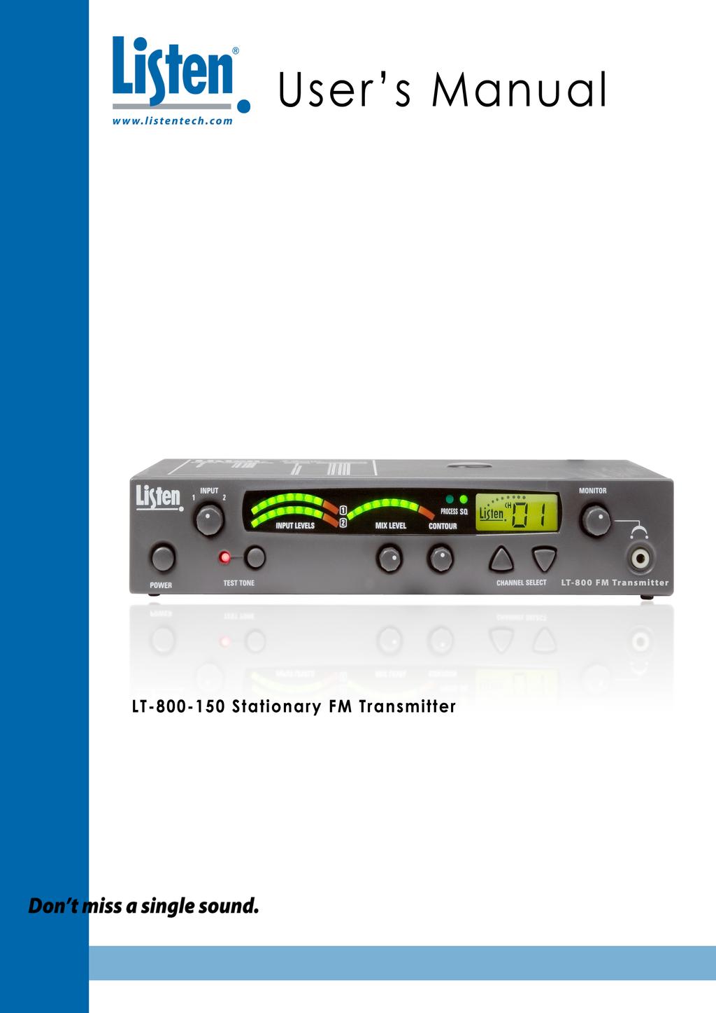
10 LT-800 Quick Reference LT-800 Front Panel: Controls & Displays Adjust audio input levels of Input 1 and Input 2 here. See page 11 for more information. Indicates audio input level of Input 1 and Input 2. Shows mixed audio level. Indicates Process Mode is active. Indicates Super Quiet mode is active. Top mount antenna connection: Remove rubber plug and screw antenna in place. LCD: Shows which channel is selected. Monitor Port: Plug in a headset and adjust volume. Power ON / OFF Test Tone: Activates a tone to aid system setup. Mix Level: Adjust so the Mix Level meter occasionally lights the red LED. Contour: Equalization adjustment. Turn counter-clockwise for voice and clockwise for music. Channel Select Up: Press for 3 seconds to lock on current channel. Channel Select Down: Press for 8 seconds to enter program mode. See page 8 for more information. LT-800 Back Panel: Connections & Settings Remote Antenna Connection: Mix Output: These connectors See page 19 or the Listen contain a mix of Input 1 and website for details on antennas Input 2. They are unbalanced that can be attached here. phono connectors; and the output level is -10 dbu. Input 2: Set switch to match the level of your Input 2 audio source, not used to increase or decrease level by +10 dbu. Input 1: Used for balanced connection of a microphone or line level input. This combination connector accepts either XLR or ¼ phono plugs. 12 VDC 1.3 A Set RF Power level here (¼, ½, and Full). See page 8 for guidelines on setting power levels. The Listen LA-207 power supply connects here. Input 2: Connect unbalanced audio to these phono connectors, input level -10 dbu or +10 dbu. Select Line, Mic or Mic+Phantom Power. Line is balanced 0 dbu input level, Mic is -55 dbu, +12 VDC supplied in PH Power position. If not using input 1, leave in line position. 6
11 LT-800 Setup Instructions 1 2 Unpack the Product Remove outer packaging and plastic cover. Inspect for physical damage. Mount in Rack (if necessary) If rack mounting the unit, install the optional rack mount kit (part LA-326) according to the instructions included with the kit, then install the LT-800 in the rack. NOTE: If rack mounting, you will need to use a rear connection antenna. Rack Mount with dual unit installed Rack Mount with single unit installed Shown with LT Connect Antenna Connect the antenna (not included) according to the installation instructions. Only use an antenna supplied by Listen. If you are connecting the antenna directly to the top of the LT-800, you will need to remove the rubber plug on top of the unit. If you are using a remote antenna connected to the rear of the unit, do not connect an antenna to the top connector. See page 19 for antenna options, or refer to the Listen website for remote antenna options, Coax antenna connection. Rear of LT-800 shown. LA-132 Remote Antenna See RF Reception Maximization Strategies and Coaxial Cable on page 13. LT-800 shown with top mount antenna connected through top of unit (part number LA-134) rubber plug Connect Power Plug the power supply into the power connector on the back panel, then plug the power supply into an outlet. Only use a Listen approved power supply (The LA-207, an in-line switching power supply, is the approved power supply for this unit). 12 VDC 1.3 A 7
12 LT-800 Setup Instructions (cont.) 5 Set SQ (Super Quiet) and Process Features Your transmitter is shipped to you with SQ (super quiet) enabled and Process disabled. For a detailed description of these features and when to use them, please refer to page 12. To Disable or Enable SQ and Process Features: With the unit on press and hold the channel select Down button for 8 seconds. The program (PGM) icon will appear on the LCD. Once in the program mode, Program icon the SQ and Process features can be turned on and off by pressing the channel select buttons. Press the channel select Up button to toggle between Process On and Off. Press the channel select Down button to toggle between SQ On and Off. LED lit when Process is enabled If the green LED is illuminated on the front panel, that feature is enabled. Once you have enabled or disabled the features as desired, let the transmitter exit the program mode by waiting 5 seconds. LED lit when SQ is enabled 6 Set RF Power Set the RF POWER switch on the back of the unit to 1/4, 1/2, Full (Level is indicated on the LCD display). The amount of transmitted RF power that you will need depends on your application. If you are operating multiple transmitters in the same environment, it is best to set the transmitters output power to its lowest level to reduce the possibility of interference. Back of LT-800 unit 12 VDC 1.3 A Full power 1/2 power 1/4 power - + 8
13 LT-800 Setup Instructions (cont.) 7 Connect Audio Inputs The LT-800 has two audio input options: Input 1 and Input 2. Input 1 is a balanced connection using either an XLR or 1/4 phono connector. Input 2 has two unbalanced mixing phono connectors. Use Input 1 if you are using a microphone or if you have a balanced connection such as from a professional audio mixer (you can also use Input 1 for unbalanced connections). Use Input 2 to connect to an unbalanced audio source. Input 1 Input 1 offers a choice of balanced XLR or 1/4 phono connector. Plug your microphone into Input 1 and move the input select switch to Mic (for dynamic microphones) or Mic + PH Power (for condenser microphones). Plug your balanced or unbalanced audio source into Input 1. Use the following diagram. XLR Wiring - + Line Back of LT-800 with XLR connected to Input 1 Mic Mic with Phantom Power 12 VDC 1.3 A 1/4 Phone Wiring Input 2 Plug your unbalanced audio source into Input 2 and select the audio level switch for -10 dbu or +10 dbu, to match the audio level coming from your equipment
14 LT-800 Operating Instructions 1 Power Unit On Turn power on by pressing the power button. 2 Select a Channel Select the transmit channel by pressing the channel select UP and DOWN buttons. See Channel Selection on page 14 for more information. - + Channel Select UP and DOWN buttons 3 Lock on Channel Once you determine your transmit channel, you can lock the transmitter on that channel. To lock on a channel hold the Channel Select Up button for 3 seconds until the padlock icon appears on the display. To unlock, repeat this process and the padlock icon will disappear. Lock icon 4 Test Tone (if necessary) To broadcast a test tone, press the test tone button. This helps to test receivers when no audio source is available. - + Press Test Tone button here 10
15 LT-800 Audio Control 1 Adjust Audio Input Level Adjust the input knob counterclockwise to add gain to Input 1. This will decrease gain to Input 2. Adjust input knob clockwise to add gain to Input 2. This will decrease gain to Input 1. If you have two audio sources connected to both Input 1 and 2, adjust the level of one input using the VU meter, then adjust the output level of the other audio source. Adjust the input level until the left VU meter(s) occasionally illuminate the red LEDs. Illumination of the red LEDs indicates the unit is in limiting. Limiting is required so that the unit does not over-modulate the transmitter. If you don t want any audio limiting to occur, make sure the red LEDs never illuminate. If you want a highly limited signal, turn the audio gain up so the red LEDs illuminate often. 2 Adjust Mix Level Adjust the mix level until the right VU meter occasionally illuminates the red LED. This is the level adjustment for the combined output from Input 1 and Input 2. 3 Adjust Contour Adjust the Contour knob counterclockwise if your audio source is mostly voice. Adjust the knob clockwise if your audio source is mostly music. The Contour knob adjusts the relative equalization of the unit. This equalization boosts or cuts frequencies above 5 khz. 11
16 Listen SQ (Super Quiet) - Improving Your Listening Experience People are accustomed to listening to low noise, high fidelity audio (delivered via CD, DVD, etc.). FM radio systems, such as those made by Listen, have more inherent noise compared to most sound systems. To minimize noise, Listen uses a noise reduction technology called ListenSQ. Both the transmitter and receiver must have the SQ feature enabled to achieve the desired results. SQ is available on new Listen systems, including the system you received in this shipment. If you are planning to use this product with older Listen systems that do not have Listen SQ, or equipment not manufactured by Listen, you must disable Listen SQ. Your Listen LT-800 has been shipped to you with the SQ feature enabled. You may need to disable the SQ function for one or more of the following reasons: You are using your new Listen LT-800 with older version Listen receivers that do not have the SQ function. You are using your new Listen LT-800 with equipment supplied by other manufacturers (Listen is the only manufacturer using SQ Technology). You expect that end users will bring and use their own receivers that don t have the SQ function. NOTE: See page 8 to enable or disable SQ (Super Quiet). SQ Summary SQ is NOT squelch SQ improves noise performance by at least 20 db SQ is NOT compatible with older version Listen products SQ is NOT compatible with other manufacturers products To work properly, SQ must be enabled for both the transmitter and receivers SQ can be disabled to permit operation with older Listen products or other manufacturers products Process Mode Process mode is used for Audio Gain Control (AGC). With the process mode enabled, the LT-800 will automatically adjust for inconsistent signal input levels by raising or lowering the signal level accordingly to provide a consistent sound output level. This feature should be used in applications where a consistent sound level is important and the input levels vary substantially. Typically you would not want to engage the Process Mode when a speaker s emphasis is critical to the message they are conveying. 12
17 RF Reception Maximization Strategies For proper and dependable operation, Listen receivers need to receive a strong and consistent signal from the originating transmitter. Note that on portable receivers the headset wire is the receiving antenna. The following strategies should be used maximize to this signal: When designing and installing your system, keep in mind that the location of both the transmitting and receiving antennas is critical to maximize broadcast range. Eliminate or minimize obstructions between the transmitting and receiving antenna. Minimize the distance between the transmitting and receiving antennas. Move transmitting and receiving antennas away from metal or conductive objects. Place the transmitting antenna as high as possible. Orient both transmitting and receiving antennas vertically. Position the RF Power switch on the back of the LT-800 to full RF Power, unless lower power is acceptable (see page 8). Keep coaxial cable from transmitter to antenna as short as possible. CAUTION: When installing antennas, ensure the antenna is clear of power lines. Coaxial cable, connectors, and optional antenna mounting kits are available from Listen. See page 19-20, visit or ask your dealer for details. Coaxial Cable The antenna for the LT-800 can be mounted directly on the unit if desired. However, you may find that the unit will provide better performance when the antenna is located elsewhere. If you plan to mount the antenna in a different location other than the top of the unit, you must use cable and connectors rated at 50 ohms. Although cable used for cable TV installations looks similar to this cable, it will not work with your Listen system. If you need to run cable over a length greater than 75 feet for 150 MHz applications or to maximize broadcast range, Listen recommends that you use RG-8 cable rather than RG-58. RG-8 is a lower loss cable, meaning that more of your signal will reach the antenna. Long cable runs can result in signal degradation due to the loss characteristics of the cable. When using RG-58 with a 150 MHz transmitter, there is an average* loss of 6 db per 100 feet of cable (A 3 db loss means half of your power has been lost.) However, it is better to suffer coaxial power loss than to try to shoot your signal through obstacles! Obstacles, especially metal, can create drop-outs or reflections of your signal that will result in poor listening conditions. *NOTE: There are many varieties of 50 ohm, RG-58 and RG-8 cables. You may purchase a cable that is better or worse than this value. Please check with the cable vendor or manufacturer for exact specifications. 13
18 Channel Selection It is important to choose channels that are free from interference to achieve proper operation of your Listen equipment. This process is trial and error. Before turning on the transmitter, listen to the wide band channels on the receivers (channels 1-6). Listen to the audio through the headphone or via the speaker and choose a channel with the least amount of interference. Unless you are interfacing with an existing narrowband transmission system, always use a wide band channel. If you are using multiple channels follow this process: 1. Same Space: If you are using multiple transmitters in the same space, the most number of channels that will work simultaneously is six at 150 MHz. With all of the transmitters off, listen for interference on all the wide band channels via the headphone jack on a Listen receiver. Using the frequency chart on page 15, eliminate any channels that have noticeable interference. Now choose the channels with the widest channel spacing. It is recommended that adjacent channels be spaced at least 300kHz. 2. Distributed Spacing: If you are using transmitters that are spread out over space, you can achieve more simultaneous broadcast channels. However, it is critical that your receiver(s) be located as close to its transmitter as possible. You can use adjacent channels (see frequency chart on page 15) in this case as long as the adjacent channel transmitter is at least 50% further away from the receiver as its transmitter. It is highly recommended that after channel selection has been achieved, you lock the channel so that it cannot be changed by the user. To accomplish LOCK on the LT-800, press the UP button for 3 seconds. Repeat the process to unlock. Wide Band Recommendation Listen recommends that you always use a wide band channel unless you need to be compatible with existing narrow band receivers from other manufacturers. Wide band channels have lower noise than their narrow band counterparts. 150 MHz The LT MHz operates on 6 wide band channels and 26 narrow band channels. 1-6 = Wide Band Channels 7-32 = Narrow Band Channels 14
19 150 MHz Frequency Chart Channel Frequency
20 LT-800 Troubleshooting Troubleshooting The LT-800 has no power Make sure the LA-207 power supply is connected to a power source and is connected to the jack marked Power Input. Make sure the POWER button is pressed in. There is no audio or the audio level is too low Make sure that your audio source is properly connected to Input 1 and/or Input 2. The Input 1 or Input 2 switches must be in the correct position for the appropriate input level. For example: if you are using the output of a mixer on Input 2, the switch should be in the -10 dbu position. If it were to be in the +10 dbu position, the level would be too low. Also, check the Input knob to ensure it is properly adjusted. You should be able to see the VU meter deflect on Input 1 or Input 2 corresponding with the input level of the audio source. You can listen to the audio source by connecting a headset to the front panel jack and adjusting the Monitor volume control. If the level of audio into the transmitter is low and can t be corrected using the level input switches, the audio processor can be turned on to boost the signal (see page 8 to set, page 12 for description of Process Mode). The audio is distorted Check to make sure you have the input level select switches in the proper position. You may be providing too much audio level for the input stage to handle. Make sure the SQ mode is set correctly on both the LT-800 and the receivers you are using. If your receivers do not have SQ, make sure the SQ mode is turned off (see page 8). There is hum in the audio Make sure you have properly grounded the audio source to the LT-800. Check the connections from the audio source to the LT-800. If you can, try to use a balanced audio source - this will reduce the chance of creating hum. Connect a ground wire from the LT-800 to ground and/or to the ground of the source audio. There is a tone The Test Tone button has been pressed (its LED light is on). Push the Test Tone button to turn off the tone. The Audio Input 1 sounds tinny If you are using an unbalanced audio source, make sure Pin 3 on the XLR or the ring on the ¼ plug is grounded (see page 9). I cannot pick up the signal on the receiver Check to make sure that they are on the same channel. Make sure the LT-800 has an antenna connected. Ensure that the receiver has an antenna (for portable products the headset is the receiving antenna). I can pick up the signal on the receiver, but it sounds like it s not tuned in Check to make sure the transmitter and receiver are on exactly the same channel. It s a good idea to lock the channels once they have been set. To lock the LT-800, press the UP button for 3 seconds (see page 10). 16
21 LT-800 Troubleshooting (cont.) Troubleshooting There is not sufficient range First make sure that the receivers you are using are operating properly, then make sure that you have an antenna connected either to the top of the LT-800 transmitter or connected to the back of the unit (but not both!). The antenna should be as high as possible and free of obstacles. In addition make sure you are using the correct antenna type for your unit. You might want to use a remote antenna (provided by Listen) that can be mounted on a mast or wall. Try using different frequencies to find one with less interference. There is interference in my transmission Ensure that the transmitter and receivers are on the same channel. Verify that there are no other transmitters on the same channel or a close channel to the one exhibiting interference. Try different channels until you find a clear channel. End users are adjusting the unit First, lock the channel by pressing and holding the channel select UP button for 3 seconds. Consider removing the Input, Mix Level and Contour knobs. You can order a rack mount kit from Listen which offers a security cover that will limit access to the unit. Several transmitters are operating in the same environment For this, you ll need to choose your transmitting frequencies carefully. See page for more details. Can I have two antennas connected to my transmitter No. The LT-800 transmitter can use only one antenna connection at a time. You may connect either a top mount antenna through the top antenna port, or a remote antenna connected to the BNC connection on the rear of the unit. If multiple antennae are simultaneously connected to both ports the transmitter will have extremely poor broadcast performance and range. 17
22 Warranty & Contacting Listen Warranty Listen Technologies Corporation (Listen) warrants its transmitters and receivers (LT-82, LT-700, LT-800, LR-42, LR-44, LR-400, LR-500) to be free from defects in workmanship and material under normal use and conditions for the useful lifetime of the product from date of purchase. Listen warrants its Stationary IR Radiators (LA-140) to be free from defects in workmanship and material under normal use and conditions for three years from the date of purchase. Listen warrants its Noise Canceling Microphone (LA-270) to be free from defects in workmanship and material under normal use and conditions for one year from date of purchase. Listen warrants its Charging/Carrying Cases (LA-306, LA-311, LA-313, LA-317, LA-318, LA-319, LA-320, LA-321, LA-322, LA-323, LA-324, LA-325) to be free from defects in workmanship and material under normal use and conditions for one year from date of purchase. All other products and accessories are warranted for 90 days from date of purchase. This warranty is only available to the original end purchaser of the product and cannot be transferred. Warranty is only valid if warranty card has been returned within 90 days of purchase. This warranty is void if damage occurred because of misuse or if the product has been repaired or modified by anyone other than a factory authorized service technician. Warranty does not cover normal wear and tear on the product or any other physical damage unless the damage was the result of a manufacturing defect. Listen is not liable for consequential damages due to any failure of equipment to perform as intended. Listen shall bear no responsibility or obligation with respect to the manner of use of any equipment sold by it. Listen specifically disclaims and negates any warranty of merchantability or fitness of use of such equipment including, without limitation, any warranty that the use of such equipment for any purpose will comply with applicable laws and regulations. The terms of the warranty are governed by the laws of the state of Utah. In the first ninety days after purchase, any defective product will be replaced with a new unit. After 90 days, Listen will, at its own discretion either repair or replace transmitters and receivers with a new unit or a unit of similar type and condition. Product that is not covered under warranty shall be repaired or replaced with a unit of similar type and condition based on a flat fee. Contact Listen for details. This limited warranty, prices and the specifications of products are subject to change without notice. Contacting Listen If technical service is needed, please contact Listen. Pre-authorization is required before returning Listen products. If products were damaged in shipment, please contact the carrier, then contact Listen for replacement or repair requirements payable by the carrier. Listen s corporate headquarters are located in Bluffdale, Utah U.S.A. and are open Monday through Friday, 8am to 5pm Mountain Time Heritagecrest Way Bluffdale, Utah North America fax support@listentech.com 18
 LA-134 Telescoping Top")


23 Optional Accessories Antenna Accessories LA-132 Universal Antenna Kit LA Helical Antenna (150 MHz) LA-134 Telescoping Top Mounted Antenna (150 MHz) LT-800 Rack Mount Accessories LA-135 Antenna Kit for Rack Mount LA-326 Universal Rack Mounting Kit Includes components for single and dual rack configuration and a security cover NOTE: Rack mounted units cannot use the LA-134 top mounted antenna. 19
 Cable & Connectors")


 LA-127 RG-58 BNC")


24 Optional Accessories (cont.) Cable & Connectors Accessories LA-112 RG Ohm Coaxial Cable (per ft.) LA-113 RG-8 50 Ohm Low-Loss Coaxial Cable (per ft.) LA-127 RG-58 BNC Connector LA-128 RG-8 BNC Connector Microphone Accessories LA-261 Lavalier Microphone LA-262 Over-the-Head Microphone LA-270 Noise Canceling Microphone LA-274 Hand-Held Microphone LA-276 Collar Microphone LA-277 Conferencing Microphone LA-278 Behind-the-Head Microphone LA-279 Over-the-Ear Microphone Presentation Style LA-280 ¼ in. to 3.5 mm Microphone Adapter for LT-800/LT-82 NOTE: To use Listen microphones you must use a converter (LA-280) to adapt the 3.5 mm connection to a 1/4 phono connection. 20
25 Notes 21
26 22 Notes
27 Notes 23
28 Listen Technologies Corporation Heritagecrest Way Bluffdale, Utah , U.S.A North America fax Printed in China 2009 Listen Technologies Corporation All Rights Reserved
Dear Valued Customer,
 Dear Valued Customer, Thank you for choosing Listen! All of us at Listen are dedicated to providing you with the highest quality products available. We take great pride in their outstanding performance
LT-800 Stationary FM Transmitter
 LT-800 Stationary FM Transmitter Thanks to its outstanding audio quality, the Listen LT-800 Stationary Transmitter can be used in a variety of applications. The LT-800 is connected to your main audio system,
LT-800 Stationary Transmitter
 LT-800 Stationary Transmitter Configuration Stationary FM Transmitter (72 MHz) Stationary FM Transmitter (216 MHz) Stationary FM Transmitter (863 MHz) Thanks to its outstanding audio quality, the Listen
Dear Valued Customer,
 Dear Valued Customer, Thank you for choosing Listen! All of us at Listen are dedicated to provide you with the highest quality products available. We take great pride in their outstanding performance because
Dear Valued Customer,
 Dear Valued Customer, Thank you for choosing Listen! All of us at Listen are dedicated to providing you with the highest quality products available. We take great pride in their outstanding performance
Assistive Listening Language Interpretation Soundfi eld Tour Group Conferencing
 Dear Valued Customer, Thank you for choosing Listen! All of us at Listen are dedicated to providing you with the highest quality products available. We take great pride in their outstanding performance
LT-700 Portable FM Display Transmitter
 LT-700 Portable FM Display Transmitter The Listen LT-700 Portable Transmitter will broadcast your presenters or interpreters voice to everyone in the audience, without having to carry a microphone or be
Synthesized Base Station Transmitter
 BST-25 OPERATOR S MANUAL (216 MHz) Synthesized Base Station Transmitter 357 West 2700 South Salt Lake City, Utah 84115 Phone: (800) 496-3463 Fax: (801) 484-6906 http://www.comtek.com INTRODUCTION BST-25
Dear Valued Customer,
 Dear Valued Customer, Thank you for choosing Listen! All of us at Listen are dedicated to providing you with the highest quality products available. We take great pride in their outstanding performance
User s Manual Listen Microphones
 User s Manual Listen Microphones Includes: LA-261 Lapel Microphone LA-262 Over-the-Head Microphone LA-268 Over-the-Ear Microphone LA-270 Noise Canceling Microphone LA-272 Over-the-Head Microphone with
Synthesized Base Station Transmitter
 BST-75 OPERATOR S MANUAL (72-76 MHz) Synthesized Base Station Transmitter 357 West 2700 South Salt Lake City, Utah 84115 Phone: (800) 496-3463 Fax: (801) 484-6906 www.comtek.com TABLE OF CONTENTS Introduction...
User s Manual LR-100 Stationary Receiver / Power Amplifier
 User s Manual L-100 Stationary eceiver / Power Amplifier Don t miss a single sound. Listen. Listen Technologies Corporation 8535 South 700 West, Suite A Sandy, Utah 84070-2515 USA Telephone: +1.801.233.8992
User s Manual LT-700 Portable Transmitter
 User s Manual LT-700 Portable Transmitter Listen Technologies Corporation 8535 South 700 West, Suite A Don t miss a single sound. Listen. Sandy, Utah 84070-2515 USA Telephone: +1.801.233.8992 Toll Free
ListenRF Stationary RF Brochure
 ListenRF Stationary RF Brochure Connecting People to Positive Expereinces Listen Technologies Personalize. Simplify. Customize. Whether in a theater, house of worship, or at a sporting venue, individuals
Personalize. Simplify. Customize.
 Personalize. Simplify. Customize. Whether in a theater, house of worship, or at a sporting venue, individuals want to experience every word and every moment. That s what they came for, and they deserve
WIR TX90. SoundPlus Infrared Transmitter INFRARED SPECIFICATION DATA
 INFRARED SPECIFICATION DATA Cinemas Simultaneous Interpretation Audio Description Conferences Multi-Media Rooms Boardrooms Courtrooms Schools Universities Churches WIR TX90 SoundPlus Infrared Transmitter
WIR TX90. SoundPlus Infrared Transmitter INFRARED SPECIFICATION DATA
 INFRARED SPECIFICATION DATA Cinemas Simultaneous Interpretation Audio Description Conferences Multi-Media Rooms Boardrooms Courtrooms Schools Universities Churches WIR TX90 SoundPlus Infrared Transmitter
PR-216. High Performance Personal Receiver PR-216 OPERATOR S MANUAL
 PR-216 OPERATOR S MANUAL PR-216 High Performance Personal Receiver 357 West 2700 South Salt Lake City, Utah 84115 Phone: (800) 496-3463 Fax: (801) 484-6906 http://www.comtek.com TABLE OF CONTENTS Introduction...
PA WATT PORTABLE PA SYSTEM PRODUCT MANUAL
 PA-5150 5 150-WATT PORTABLE PA SYSTEM PRODUCT MANUAL THANK YOU FOR CHOOSING POLSEN. The Polsen PA-5150 is an active PA system that s ideal for solo performers or vocalists. It can be used as a PA system
PPA 377. Personal PA FM Listening System FM SPECIFICATION DATA. System Includes:
 FM SPECIFICATION DATA Churches Schools Auditoriums Conference Rooms Theaters PPA 377 Personal PA FM Listening System The PPA 377 features the T35 high performance transmitter: powerful microprocessor,
Model 1791 VHF Radio User's Manual
 Model 79 VHF Radio User's Manual ALL WEATHER INC 65 NATIONAL DRIVE SACRAMENTO, CA 95834 WWW.ALWEATHERINC.COM 79 VHF RADIO USER'S MANUAL CONTENTS INTRODUCTION... Description... Transmitter Module... Power
AUDIOLINK PRO. Warranty Conditions INSTRUCTION MANUAL M110 INFRARED TRANSMITTER
 AudioLink PRO M110 Warranty Conditions ELT Corp. warrants that this AudioLink PRO product is free from defects in material and workmanship for the period of two years from the date of purchase. If this
310 DIVERSITY CAMERA-MOUNT UHF WIRELESS MICROPHONE SYSTEM
 310 DIVERSITY CAMERA-MOUNT UHF WIRELESS MICROPHONE SYSTEM 310UDR - 35BT - 35HT - 35XT INSTRUCTION MANUAL Thank you for purchasing the Azden 310 Diversity Wireless Microphone system. The components included
32 CHANNEL SELECTABLE CH MHZ DOWN VOLUME
 KARAOKE Professional UHF Wireless Microphone System VM-92U Operating Instructions UHF Frequency 64 Selectable Better Music Builder UHF MIC WIRELESS SYSTEM VM-92U 32 CHANNEL SELECTABLE 248 13.10 CH MHZ
OWNER S MANUAL 311DRH 311DR 221R 211R 200R 31LT 31IT 32BT 32IT 31HT 31XT
 VHF PERFORMANCE SERIES WIRELESS MICROPHONE SYSTEMS OWNER S MANUAL 311DRH 311DR 221R 211R 200R 31LT 31IT 32BT 32IT 31HT 31XT AZDEN CORPORATION P.O. Box 10-147 New Hyde Park Road Franklin Square, NY 11010
330 DUAL-CHANNEL CAMERA-MOUNT UHF WIRELESS MICROPHONE SYSTEM
 330 DUAL-CHANNEL CAMERA-MOUNT UHF WIRELESS MICROPHONE SYSTEM 330UPR - 35BT - 35HT - 35XT INSTRUCTION MANUAL Thank you for purchasing the Azden 330 Dual-Channel Wireless Microphone system. The components
PLA-240. Small Room Loop Amplifier System. USER Manual MAN 211A
 PLA-240 Small Room Loop Amplifier System USER Manual MAN 211A Overview Thank you for purchasing the PLA 240 Small Room Loop Amplifier System. The PLA 240 Loop System provides a practical solution for hearing
Installation Guide & User Manual
 Installation Guide & User Manual SoundPlus Infrared Listening System Model WIR TX90, Two Channel System Model WIR SYS 90 ADV, Two Channel System Model WIR SYS 91V, Two Channel System Transmitter Model
Hearing Helper. Wireless FM Listening System. Manual and User Guide. Transmitter Model T800 Optional Receiver Model R863 MAN 143C
 Hearing Helper Wireless FM Listening System Manual and User Guide Transmitter Model T800 Optional Receiver Model R863 Hearing Helper T800 Transmitter Manual and User Guide Contents System Overview... 3
Professional UHF Rechargeable Wireless Microphone System POWER ON/OFF BATTERY CHARGE. Green Light (Full) Better Music Builder DOWN VOLUME
 Better Music Builder DOWN VOLUME") Green Light (Full) KARAOKE Professional UHF Rechargeable Wireless Microphone System VM-93C Operating Instructions UHF Frequency 64 Selectable POWER ON/OFF CHARGE Better Music Builder VM-93C CHARGER UHF
Green Light (Full) KARAOKE Professional UHF Rechargeable Wireless Microphone System VM-93C Operating Instructions UHF Frequency 64 Selectable POWER ON/OFF CHARGE Better Music Builder VM-93C CHARGER UHF
Model 1792 VHF Radio. User s Manual. Rev. B FAA APPROVED NOT FAA APPROVED. ECP Dec 30
 Model 1792 VHF Radio FAA APPROVED ECP202 2014 Dec 30 NOT FAA APPROVED User s Manual Rev. B All Weather Inc. 1165 National Drive Sacramento, CA 95834 USA 800.824.5873 www.allweatherinc.com Copyright 2011,
ENCORE 200 VHF Bass Wireless Microphone System
 ENCORE 200 VHF Bass Wireless Microphone System Nady Wireless Systems are type accepted under FCC rules parts 90, 74 and 15. The device complies with RSS-210 of Industry & Science Canada. Operation is subject
FMR622S DUAL NARROW BAND SLIDING DE-EMPHASIS DEMODULATOR INSTRUCTION BOOK IB
 FMR622S DUAL NARROW BAND SLIDING DE-EMPHASIS DEMODULATOR INSTRUCTION BOOK IB 1222-22 TABLE OF CONTENTS SECTION 1.0 INTRODUCTION 2.0 INSTALLATION & OPERATING INSTRUCTIONS 3.0 SPECIFICATIONS 4.0 FUNCTIONAL
Better Music Builder POWER RF AF
 Professional UHF Wireless Microphone System VM-82U Operating Instructions Better Music Builder UHF WIRELESS SYSTEM VM-82UH UHF DUAL CHANNEL RECEIVER VM-82U Better Music Builder UHF 64 SELECTABLE WIRELESS
model 101 single channel microphone preamplifier owner s manual Rev C
 2434 30th street, boulder, CO 80306-0204 USA tel 303.443.7454 fax 303.444.4634 info@gracedesign.com / www.gracedesign.com single channel microphone preamplifier Rev C all contents Grace Design/ Lunatec
WS-29 DUAL CHANNEL WIRELESS BELTPACK
 WS-29 DUAL CHANNEL WIRELESS BELTPACK USER MANUAL Issue March 2011 ASL Intercom BV DESIGNED AND MANUFACTURED BY: ASL INTERCOM BV ZONNEBAAN 42 3542 EG UTRECHT THE NETHERLANDS PHONE: +31 (0)30 2411901 FAX:
Telex. Operating Instructions UR-700
 Telex Operating Instructions UR-700 GENERAL INFORMATION The Telex Model UR-700 Receiver and associated Transmitters is a full diversity system operating within the frequency range of 690 to 725 MHz on
Instruction Kit MIXER AMPLIFIER GT 60C GT 125C. GROMMES-PRECISION SINCE-46
 Instruction Kit GT 60C GT 125C MIXER AMPLIFIER GROMMES-PRECISION 1-800-SINCE-46 www.grommesprecision.com Thank you for purchasing from Grommes~Precision! Grommes~Precision and its commercial audio division,
FCC STATEMENT This device complies with part 74, Subpart H of the FCC rules. Operation is subject to the following two conditions: (1)This device may
This device may") FCC STATEMENT This device complies with part 74, Subpart H of the FCC rules. Operation is subject to the following two conditions: (1)This device may not cause harmful interference and (2) This device
FCC STATEMENT This device complies with part 74, Subpart H of the FCC rules. Operation is subject to the following two conditions: (1)This device may not cause harmful interference and (2) This device
PDWM4400 VHF WIRELESS SYSTEM PDWM4400 VHF WIRELESS SYSTEM OPERATION MANUAL
 A.Overall system Oscillation mode: Quartz controlled Carrier Frequency Range: VHF 169-270MHz Stability: 0.005% Max Deviation: 56KHz with level limiting Dynamic Range: 100dB S/N Ratio: 80dB T.H.D: 0.5%
Table of Contents. Overview... 3
 User Guide Table of Contents Overview.................................................... 3 Powering A.C.E............................................... 4 Inputs & Outputs..............................................
evolution wireless G4 ew 300 G4-Base SK-RC Bodypack Base Set
 1/7 Best choice for your business, top of the class in education. The G4 300 Series uses the power of an increased switching bandwidth of up to 88 MHz. New frequency ranges allow to operate multi-channel
2007 MFJ ENTERPRISES, INC.
 Model MFJ-643 INSTRUCTION MANUAL CAUTION: Read All Instructions Before Operating Equipment MFJ ENTERPRISES, INC. 300 Industrial Park Road Starkville, MS 39759 USA Tel: 662-323-5869 Fax: 662-323-6551 VERSION
evolution wireless G4 ew 300 G4-HEADMIC1-RC Bodypack Headmic Set
 1/8 Best choice for your business, top of the class in education. The G4 300 Series uses the power of an increased switching bandwidth of up to 88 MHz. New frequency ranges allow to operate multi-channel
HX-3. Headphone Distribution Amplifier User Guide and Technical Information
 HX-3 Headphone Distribution Amplifier User Guide and Technical Information Sound Devices, LLC 300 Wengel Drive Reedsburg, WI USA +1 (608) 524-0625 fax: +1 (608) 524-0655 Toll-Free: (800) 505-0625 www.sounddevices.com
MFJ SIGNAL ENHANCER II
 MFJ SIGNAL ENHANCER II Model MFJ-752D INSTRUCTION MANUAL CAUTION: Read All Instruction Before Operating Equipment MFJ ENTERPRISES, INC. P.O. BOX 494, MISSISSIPPI STATE, MS 39762, USA 925-0037D-752D-REV
441 DUAL CHANNEL 15 BAND 2/3 OCTAVE GRAPHIC EQUALIZER 451 SINGLE CHANNEL 31 BAND 1/3 OCTAVE GRAPHIC EQUALIZER
 441 DUAL CHANNEL 15 BAND 2/3 OCTAVE GRAPHIC EQUALIZER 451 SINGLE CHANNEL 31 BAND 1/3 OCTAVE GRAPHIC EQUALIZER 455 DUAL CHANNEL 31 BAND 1/3 OCTAVE GRAPHIC EQUALIZER The new ART 400 Series of Precision Graphic
Mid-Level UHF Dual Channel Wireless Microphone System
 Mid-Level UHF Dual Channel Wireless Microphone System 7 8 9 10 3 Box contents outputs - Dual UHF Wireless receiver with mixed XLR and1/ - 6.5mm to 3.5mm audio cable adapter - Two antennas - Two handheld
900 MHz Digital Wireless Indoor/Outdoor Speakers
 4015007 900 MHz Digital Wireless Indoor/Outdoor Speakers User s Manual This 900 MHz digital hybrid wireless speaker system uses the latest wireless technology that enables you to enjoy music and TV sound
LA-140 Stationary IR Radiator
 LA-140 Stationary IR Radiator The LA-140 IR radiator/emitter packs high infrared power in a small and attractive design, with your choice of grey LA-140-GY (Grey) LA-140-WH (White) or white packaging.
IR Radiator. Configuration. Architectural Specification. Highlights. Used With
 IR Radiator Don t miss a single sound. The LA-140 IR radiator/emitter packs high infrared power in a small and attractive design, with your choice of grey or white packaging. Designed for easy installation
DM 800H Twin Handheld UHF System (863.0Mhz-865.0Mhz)
") DM 800H Twin Handheld UHF System (863.0Mhz-865.0Mhz) User Manual Order code: MIC78 Safety advice WARNING FOR YOUR OWN SAFETY, PLEASE READ THIS USER MANUAL CAREFULLY BEFORE YOUR INITIAL START-UP! Before
DM 800H Twin Handheld UHF System (863.0Mhz-865.0Mhz) User Manual Order code: MIC78 Safety advice WARNING FOR YOUR OWN SAFETY, PLEASE READ THIS USER MANUAL CAREFULLY BEFORE YOUR INITIAL START-UP! Before
i. AM. Radio Transmitter Installation and Operation Easy to follow instructions on how to program and use your Model 5.0 i. AM.
 i. AM. Radio Transmitter Installation and Operation Easy to follow instructions on how to program and use your Model 5.0 i. AM. Radio Transmitter Contents Quick Start...3 Front and Rear Panel Controls...5
User Manual. ilive 2 Wireless microphone system
 User Manual ilive 2 Wireless microphone system Safety instructions When using this electronic device, basic precautions should always be taken, including the following: 1 Read all instructions before using
HX-3 Headphone Distribution Amplifier
 SOUND DEVICES HX-3 Headphone Distribution Amplifier User Guide and Technical Information Sound Devices, LLC 300 Wengel Drive Reedsburg, WI 53959 USA Voice 608.524.0625 Fax 608 524.0655 www.sounddevices.com
WIR SYS 3. SoundPlus Value Courtroom System ADA Courtroom Assistive Listening System INFRARED SPECIFICATION DATA
 INFRARED SPECIFICATION DATA Courtrooms Military Installations Embassies Consulates Political Offices WIR SYS 3 SoundPlus Value Courtroom System ADA Courtroom Assistive Listening System The Value Courtroom
Model 7000 Low Noise Differential Preamplifier
 Model 7000 Low Noise Differential Preamplifier Operating Manual Service and Warranty Krohn-Hite Instruments are designed and manufactured in accordance with sound engineering practices and should give
HQ-31 HQ-15 USER S GUIDE SINGLE CHANNEL 31 BAND 1/3 OCTAVE GRAPHIC EQUALIZER DUAL CHANNEL 15 BAND 2/3 OCTAVE GRAPHIC EQUALIZER
 HQ-31 SINGLE CHANNEL 31 BAND 1/3 OCTAVE GRAPHIC EQUALIZER HQ-15 DUAL CHANNEL 15 BAND 2/3 OCTAVE GRAPHIC EQUALIZER USER S GUIDE GENERAL INFORMATION SINGLE CHANNEL 31 BAND 1/3 OCTAVE GRAPHIC EQUALIZER WITH
Courtrooms Schools Universities Cinema Churches
 SoundPlus W TX925 Infrared System Description: The W TX925 is ideal for language interpretation for up to two languages. It can operate up to 18, sq. ft. in two channel mode or 28, in single channel mode.
evolution wireless G4 ew 500-G4-MKE 2 Lavalier Set
 1/7 The pro s choice. Renowned sound engineers rely on ew 500 G4 s flexibility, especially when handling multi-channel settings on the world s music stages. Up to 88 MHz bandwidth, up to 32 channels. Ethernet
USER'S MANUAL UHF BAND
 USER'S MANUAL I UHF BAND MICROPHONE SYSTEM I 1440-8120-01 NOTE. HmmHmmmJ i... 1 FCC Statement MICROPHONE SYSTEM Table of Contents 1. Introduction......... 1 2. Safety... 1 3. Environment... 1 4. Wireless
eti Ultimate USB microphone for professional recording
 eti Ultimate USB microphone for professional recording 3 Congratulations on your purchase of The Yeti, the most advanced and versatile multi-pattern USB microphone roaming the wild today. The Yeti is
Big Knob Radio User s Guide Item Number: All brand names and trademarks are the property of their respective owners
 Big Knob Radio User s Guide Item Number: 11009726 All brand names and trademarks are the property of their respective owners Contents Overview...3 Quick Start Guide...3 Package Contents...3 Diagram of
4 Channel Frequency Conscious Noise Gate. Operation Manual
 4 Channel Frequency Conscious Noise Gate Operation Manual June 2005 This page has been left intentionally blank for your notes Page 2 CONTENTS 1.0 OVERVIEW 4 2.0 DESCRIPTION OF CONTROLS 5-7 2.1 Bypass
SoundPals. DAC-24 User Guide. Stereo D-to-A converter
 SoundPals DAC-24 User Guide Stereo D-to-A converter Printing History SoundPals DAC-24 D-to-A converter Rev. N/C SEPTEMBER 2016 Printed in U.S.A. Part Number 08-2044-00 The information contained in this
Contents. System Components...1. Functions of the VESR Receiver...2. Functions of the VSCR Receiver...3
 Contents System Components...1 Functions of the VESR Receiver...2 Functions of the VSCR Receiver...3 Functions of the HH18 Hand Held Transmitter...4 Functions of the MBP18 Body Pack Transmitter...5 Troubleshooting...6
evolution wireless G4 ew 100 G4-ME2 ew 100 G4-ME4 Lavalier Set
 1/7 Versatile wireless systems for those who sing, speak or play instruments with up to 42 MHz tuning bandwidth in a stable UHF range and fast, simultaneous setup of up to 12 linked systems. The perfect
Manual and User Guide
 Manual and User Guide TV Talker FM System Model WFM 260 Model WFM 270 Transmitter Model WFM TX260 Receiver Model WFM RX260 Receiver Model WFM RX270 MAN 151H 2011 Williams Sound, LLC Contents Page System
Denoiser Box. Analog signal processing device STC-L254. Technical Description
 Denoiser Box Analog signal processing device STC-L254 Technical Description Technical Description Dear Customer, Thank you for purchasing this product. For optimum performance and safety please read these
Overview. Thank you for purchasing the Suhr Eclipse Dual Overdrive/Distortion Pedal.
 User Guide Table of Contents Overview 3 Getting Connected 4 Channel Selection / Bypass 5 Controls 6 Battery Monitor 7 FX Link (External Control) 8 Sample Settings 9 Technical Specifications 10 Warranty
Technical Equipment Specification
 STATE OF CALIFORNIA Office of the State Chief Information Officer Public Safety Communications Division Technical Equipment Specification Equipment Type: Transmitter/Receiver Mobile Relay/Base/Control
CCR24T CCR24R. User s Guide WIRELESS TRANSMITTER SYSTEM WARRANTY SERVICE CARD WARRANTY CARD
 WARRANTY SERVICE CARD WARRANTY CARD PRODUCT NAME Wireless Transceiver System PERIOD MODEL NAME CCR24GEN YEAR PURCHASE DATE.. 200_ From the date of WARRANTY PERIOD.. 200_ purchase. CUSTOMER S ADDRESS :
evolution wireless G4 ew 300 G4-865-S Handheld Set
 1/7 Best choice for your business, top of the class in education. The G4 300 Series uses the power of an increased switching bandwidth of up to 88 MHz. New frequency ranges allow to operate multi-channel
Hearing Helper T800 Transmitter Wireless FM Listening System
 Manual and User Guide Hearing Helper T800 Transmitter Wireless FM Listening System Transmitter Model T800 Optional Receiver Model R863 MAN XXX 2008 Williams Sound Corp. Hearing Helper T800 Tr a n s m i
User Instructions. Model PS-2001L. Power Supply. Model SPS Power Supply. Audiocom Intercom Systems Rev. A, 4/2001.
 User Instructions PS-00L Model PS-00L Power Supply SPS-00 Volume Model SPS-00 Power Supply Audiocom Intercom Systems 950-7699-000 Rev. A, /00 FCC Statement This equipment uses, and can radiate radio frequency
DL50/K AUDIO-FREQUENCY INDUCTION LOOP KIT
 DL50/K AUDIO-FREQUENCY INDUCTION LOOP KIT INSTALLATION & SET-UP MANUAL Please read these instructions carefully before installing your DL50 induction loop system About this kit... 2 What is an induction
Quick Start Guide. HMa-941. Plug-On Transmitter. For FCC Part 74 licensed operators
 Quick Start Guide HMa-941 Plug-On Transmitter Digital Hybrid Wireless U.S. Patent 7,225,135 For FCC Part 74 licensed operators Fill in for your records: Serial Number: Purchase Date: This guide is intended
UHF Wireless System CONTENTS
 UHF Wireless System USER GUIDE SUPPLEMENT KA (854 862 MHZ) CONTENTS SPECIFICATIONS............................................... 2 Furnished Accessories........................................ 5 Optional
LED PDWM 4520 PDWM 4540 PDWM 4560
 LED PDWM 4520 PDWM 4540 PDWM 4560 CATALOG 1.FOREWORD...2 2.INTRODUCTION...2 3.SYSTEM FEATURES...2 4.SYSTEM TYPE...2 5.FOUR CHANNEL RECEIVER FEATURES...3 FOREWORD Thanks for purchasing this product, please
USER S MANUAL AF LEVEL SET AF LEVEL SET AF LEVEL SET AF LEVEL SET ADS ADS ADS ADS POWER dBu BATT INFRARED
 POWER GROUP BATT CHANNEL INFRARED USER S MANUAL Contents DHXR System Components...1 DHXR4 System Components... Rack-Mounting the DHXR... Rack-Mounting the DHXR4...4 Functions of the DHXR Receiver...5 Functions
Advanced Test Equipment Rentals ATEC (2832)
") Established 1981 Advanced Test Equipment Rentals www.atecorp.com 800-404-ATEC (2832) A.H. Systems Model Active Monopole Antennas Active Monopole Antenna Series Operation Manual 1 TABLE OF CONTENTS INTRODUCTION
Established 1981 Advanced Test Equipment Rentals www.atecorp.com 800-404-ATEC (2832) A.H. Systems Model Active Monopole Antennas Active Monopole Antenna Series Operation Manual 1 TABLE OF CONTENTS INTRODUCTION
Ultimate USB & XLR Microphone for Professional Recording
 yetipro Ultimate USB & XLR Microphone for Professional Recording 3 desktop or studio, the possibilities are endless. Congratulations on your purchase of Yeti Pro, the first microphone to combine the exceptional
CON NEX HP. OWNER'S MANUAL Full Channel AM/FM Amateur Mobile Transceiver TABLE OF CONTENTS TUNING THE ANTENNA FOR OPTIMUM S.W.R..
 TABLE OF CONTENTS PAGE SPECIFICATIONS... 2 INSTALLATION... 3 LOCATION... 3 CON NEX - 4300HP MOUNTING THE RADIO... 3 IGNITION NOISE INTERFERENCE... 4 ANTENNA... 4 TUNING THE ANTENNA FOR OPTIMUM S.W.R..
2013 MFJ ENTERPRISES, INC.
 Model MFJ-868B MFJ Giant True Peak-Reading SWR/Wattmeter 1.8-60MHz MODEL MFJ-868B INSTRUCTION MANUAL CAUTION: Read All Instructions Before Operating Equipment MFJ ENTERPRISES, INC. 300 Industrial Park
DUAL LEVELAR. Two Channel Tube Compressor/Leveling Amplifier
 DUAL LEVELAR Two Channel Tube Compressor/Leveling Amplifier USER S GUIDE Introduction Thank you for purchasing the Dual Levelar and congratulations! You now own one of the most sophisticated pieces of
Fmuser FU-05D FM transmitter USER S GUIDE. Fmuser FM transmitter is a professional grade low power FM transmitter operating
 Fmuser FU-05D FM transmitter USER S GUIDE Features Fmuser FM transmitter is a professional grade low power FM transmitter operating in the commercial FM band (88.10M 107.9MHz). Create your own personal
HOOKING IT UP. Unpacking and Inspection. Installing in a Rack CHAPTER 3: Hooking It Up
 CHAPTER 3: HOOKING IT UP Unpacking and Inspection Your Studio 32 was packed carefully at the factory, and the container was designed to protect the unit during shipping. Please retain this container in
SoundPlus Infrared System Model WIR SYS 90 ADV
 escription: The 0 two channel IR transmitter combines modulator and emitter technology into a single operating unit, which reduces operating cost and eliminates precious rack space. The 0 transmitter advduces
Instruction Manual. SainSonic AX-7C FM Transmitter III. So in SONIC
 Instruction Manual SainSonic AX-7C FM Transmitter D ~ III ~ D So in SONIC CATALOG Caution... 2 Copyright... 2 FCC Information... 2 Warranty... 2 Limitation of Liability... 3 Introduction of SainSonic AX-058
EQ-AMP60 60W Mixer Amplifier
 EQ-AMP60 60W Mixer Amplifier Instruction Manual 4091 AMTC Center Drive Clearwater, FL 33764-6976 (727)531-3105 (727)531-3965 www.amtc.com Features 1. MIC 1 input with front- and rear-panel connectors 2.
UHF Wireless Microphone System
 PDWM1902 PDWM1904 PDWM3375 PDWM3378 PDWM3400 UHF Wireless Microphone System SYSTEM TYPE The Vocal Artist-UHF is a hand-held system designed for singers who desire the high quality microphones and the freedom
Assistive Listening Systems. RX-6 User s Guide
 Assistive Listening Systems RX-6 User s Guide Page ii RX-6 User s Guide Copyright Information Contents Introduction 1 Controls 2 Installing Batteries 3 Operation 3 Tuning the RX-6 4 Changing Preset Channels
900MHz Digital Hybrid Wireless Outdoor Speakers
 4015004 900MHz Digital Hybrid Wireless Outdoor Speakers User s Manual This 900 MHz digital hybrid wireless speaker system uses the latest wireless technology that enables you to enjoy music and TV sound
Wireless Microphones SE-350-WT-HAND SE-350-WT-BODY Wireless Receiver SE-350-WR-1CHD
 Wireless Microphones SE-350-WT-HAND SE-350-WT-BODY Wireless Receiver SE-350-WR-1CHD PG 2 www.snapav.com PG 3 Table of Contents 1. Before You Get Started...4 2. How It Works...4 3. Compatible Accessories...
CT-2 and CT-3 Channel Taggers OPERATION MANUAL
 CT-2 and CT-3 Channel Taggers OPERATION MANUAL Trilithic Company Profile Trilithic is a privately held manufacturer founded in 1986 as an engineering and assembly company that built and designed customer-directed
Frequency Coverage MHz RF Power Output 30W SSB / 9W AM/ 30W FM Dual Finals on Heat Sink Modes AM, FM, USB, LSB Microprocessor
 MAGNUM M-257 30W AM/ /FM/SSB 10--11 Meterr Mobile Trranscei ivverr n Prri iiccee: : US$ 250..00 eexx ssttoocckk JJaakkaarrttaa (Arrrri ( iivvi iinngg 2 d weeeekk iinn i Maarrcchh) ) SPECIFICATIONS Frequency
Talk & Listen Systems
 Talk & Listen Systems 72MHz Mini Transmitter and Receiver Part #s ARG-TX72M & ARG-TX72R Manual and User Guide User Guide Part # ARG-OM031 REVD Updated: 1/5/2017 Audio Resource Group, Inc. 405 Main Ave
WIR TX925, WIR SYS 1 Two-Channel Infrared Listening Systems
 WIR TX925, WIR SYS 1 Two-Channel Infrared Listening Systems User Manual Emitter Model WIR TX9 DC Modulator Model MOD 232 Optional Receiver Models WIR RX18, WIR RX22-4 WIR TX9 DC EMITTER MOD 232 MODULATOR
Owner s Manual DKW-3 HT. Wireless VHF Microphone System
 Owner s Manual DKW-3 HT Wireless VHF Microphone System Contents Introduction... 2 System Features... 2 Operation... 3 Specifications... 5 Service Information... 6 Warranty... 7 Introduction Thank you for
2.4GHZ WIRELESS SYSTEM FOR POLICE VIDEO RECORDING
 PW24-2 2.4GHZ WIRELESS SYSTEM FOR POLICE VIDEO RECORDING USER GUIDE Revision B Page 1 of 8 10/11/06 TABLE OF CONTENTS 1. Quick Set Up and Operation... 3 2. Installation... 4 3. Guidelines For Best Performance...