Postcard Radio Project
|
|
|
- Lorena Jones
- 5 years ago
- Views:
Transcription


1 APPLIE TEHNOLOGY & ENGINEERING Postcard Radio Project Name: ate: Grade: Section:

2 Postcard Radio Project ESIGN HALLENGE >> esign and build a simple radio that will receive an AM signal through the air without electricity riteria Your radio must have... A completed circuit board 8 meters of antenna wire An earpiece An attractive case or housing to hold all the parts Approved Materials circuit board earpiece 8 meters of wire metal tuning plate covers for front and rear of radio alligator clips Wood Paper clips Plastic NOTE: Keep track of and safeguard all materials. Points will be lost if replacement parts are needed. onstraints Your case must stay within these measurements: Maximum length: 0 cm (front to back) Maximum width: 8 cm (side to side) Maximum height: 0 cm (top to bottom) Key Points Electromagnetic (EM) radiation is pretty much all around us. When you listen to an AM or FM radio station, the sound that you hear is transmitted to your radio by the station using EM radiation as a carrier radio waves. rystal radios pick up AM radio without batteries or electricity. The broadcast station puts out enough power in the form of a radio signal. The c r y s t a l r a d i o a n t e n n a c a p t u r e s t h i s electromagnetic energy, and the signal then passes through the crystal detector and converts the signal back into sound using a diode. Key Terms Electromagnetic waves energy that can travel through air, solid materials and empty space. iode- an electronic part that allows current or waves to flow in one direction only. Wavelength- the distance between peaks of electromagnetic waves. Frequency- how often a wave peak goes by. Amplitude- the measure of something's size ecoder- separates the sound wave from the rest of the radio wave. Transmitter-an electronic device that broadcasts radio waves or signals lass ompetition Each radio will be rated as follows: No Signal: you can t hear any signal at all Inaudible Sound: you can barely hear a signal, but can t make out any words Weak Signal: you can hear a few words here and there, but nothing that makes sense Medium Signal: you can hear most words, but it still sounds scratchy 5 Strong Signal: you can clearly hear words or songs


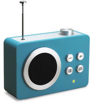
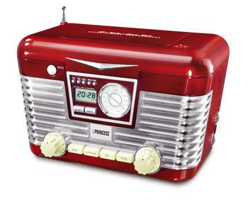
3 RESEARH Transistor radios The transistor was invented in 97, at Bell Telephone Laboratories. It was smaller, used less electricity and operated more reliably than valves. The Regency TR- was the first transistor radio available in 95 costing around 0. The development of transistor radios changed the way music could be listened to. Transistors made radios smaller and as a result more portable and affordable. Young listeners began to buy the new transistor radios to listen to their own music. The transistor radio transformed the social use of radio. Sets were now inexpensive and highly portable. Radios were no longer a piece of furniture but a personal item that could be carried everywhere, and as a result the demand for radios increased. I based radios In 958 the integrated circuit was developed by Texas Instruments. It was now possible to place all the components of an electronic circuit on a small piece of silicon. The use of small Is has allowed the design of radios to change dramatically. The design of the case is no longer defined by the circuit it contains. This has allowed designers to develop a whole new range of novel and interesting shapes to contain radios. The development of I manufacturing has resulted in surface mounted Is and hip on board constructed radios that have allowed the size of radios to shrink even more. The diagram on the right shows a mini radio that sells for a few pounds and fits onto a key ring! Future of radio The st entury has seen the introduction of digital radio. Analogue radio signals frequently suffer from interference and distortion. igital radio signals do not suffer from interference. With digital radio all the transmitters use the same frequency. This means you do not have to re-tune as you move location. A digital signal can also carry several radio programmes and data simultaneously, allowing you to see text and pictures with your radio programme.
 FM (frequency modulated) Amplitude modulation (AM) AM is easier to transmit, but can be affected by electrical interference from devices like a switch.")


4 If you look at a radio you will see that there are usually two types of radio signal that it can receive, AM and FM. AM (amplitude modulated) FM (frequency modulated) Amplitude modulation (AM) AM is easier to transmit, but can be affected by electrical interference from devices like a switch. Tall buildings or hills also affect AM radio reception. Frequency modulation (FM) The FM wave is more difficult to transmit, but it does not suffer interference as much. FM carrier waves are higher in frequency than AM. How it works Guglielmo Marconi, was the first person to show that invisible radio waves could be used for communication between two places without wires. Radio waves are part of a wider spectrum of electromagnetic waves. Light is part of this spectrum. The difference between the two is the frequency at which they vibrate. Light has a higher frequency than radio waves. Radio, television and mobile phones, all use electromagnetic waves to transmit information. Each form of communication uses a different frequency to transmit the information. By using a different frequency for each we are able to separate them. Transmitting Radio At the transmitter, the signal from the microphone is first amplified. It is then combined with a radio carrier wave, this is called modulation. The modulated signal is then further amplified and transmitted from the aerial. Receiving Radio Since we are surrounded by many radio signals, the first task for the radio receiver is to select a particular station from all the others. This is done through the tuning section of the circuit. The tuner circuit is designed to respond to one particular frequency and ignore all others. By altering the value of the capacitor in the tuning circuit, you change the frequency the circuit responds to and thus change the radio station received. The tuner section of the circuit causes the radio to receive one of the many radio signals. Now the radio has to extract the voice or music from the carrier wave. This is done with part of the radio called a demodulator. emodulation removes the original sound wave from the carrier wave. Since the sound is very weak it needs amplification so that we can hear it. The final signal is then fed to a speaker where the original voice or music can be heard again.


5 ase design There are a variety of methods of containing your electronic products. The choice depends on your design requirements. Vacuum forming is an ideal method for creating cases to hold your electronic products. High impact Polystyrene or ABS make good case moulding material. The first stage is to design and make a mould. There are a number of important features that need to be included to make a good mould design: Vacuum forming process. The mould sides must be tapered to allow the mould to be removed.. Vent holes need to be drilled to help draw the plastic when the vacuum is created.. There should be no undercuts, which will prevent the moulding being removed from the mould.. The mould needs a high standard of finish. Any marks will appear on the surface of the moulding. The vacuum forming sheet is first clamped into position around its edge by an airtight seal. The sheet is then heated from above by the radiant heaters in the machine s hood. When the sheet becomes soft and pliable, between the heating hood is removed. When the sheet is pliable and the heater has been removed, air is blown in under the sheet to stretch it. This is done to reduce the thinning on the moulding. The platen is now raised into the blown sheet. The air is then drawn from under the mould, creating a vacuum. The atmospheric air pressure above then forces the pliable sheet of plastic over the mould taking up its detailed shape. 5
6 IENTIFY THE PROBLEM In your own words... state what you ve been asked to do. I have been asked to that will Look at the rubric for this project on the last page and then answer the next two questions.. Which goal do you think will be the most challenging?. What s ONE strategy you can try to overcome it? EVELOP POSSIBLE SOLUTIONS In the boxes below, draw six (6) different versions of what your design might look like. It s very important to label the drawings to help me understand your thinking. Prototype # Prototype # Prototype # Prototype # Prototype #5 Prototype #6 6
. raw the designs in centimeters and label the dimensions.")
 Front View B - raw in the")
7 STEP WidTH WidTH LENGTH WITH Front View HOOSE A SOLUTION STEP STEP WidTH WidTH You need to create clear, specific and labeled drawings (using rulers WidTH and other drawing instruments) WidTH from three different views A (front, LENGTH top and WITH side). raw the designs in centimeters and label the dimensions. You Front View LENGTH WITH Front View will not be able to begin construction until this drawing is completed. Teacher s initial are required for approval. Follow the examples A below. A B A- HEAT Transfer the height of the shape to the side view by drawing dotted lines B - raw in the object line representing the overall width ( ½ inches or 0 blocks) Front View B - raw in the object line representing the overall height (inches or 8 blocks, you Top also have View a dot that represents B the height) - Finish drawing the object lines A- HEAT that represent Transfer the the outside A- height HEAT edges of the of shape the Transfer shape to the the side height view of by the drawing shape to dotted the side lines view by drawing dotted lines B - raw in the object line Side B representing - raw the object overall line width representing ( ½ inches the or overall 0 blocks) width ( ½ inches or 0 blocks) - raw in the object line representing - raw the object overall line height representing (inches the or 8 overall blocks, height you also (inches have or a dot 8 blocks, that represents you also the have height) a dot that represents View the height) - Finish drawing the object STEP - lines Finish that drawing represent the the object outside lines edges that represent of the shape the outside edges of the shape HEAT LENGTH Front View HEAT / HEAT / / STEP STEP Length WidTH Top View Length Length WidTH WidTH LENGTH LENGTH Top View Top /" View Front View Front View /" /" /" /" /" A - imension the overall length (either the front or top view) A - imension the overall length (either the front or top view) A - imension the overall length B - imension the overall height (either the front or side view) B -(either imension the front the overall or top height view) (either the front or side view) - imension the overall width (either the top or side view) B - imension the overall height -(either imension the front the overall or side width view) - imension (either the any top other or side edges, view) cut-outs, slants, holes, etc. (don t over dimension, it only makes the drawing look messy) - imension the overall width (either - imension the top any or other side view) edges, cut-outs, slants, holes, etc. (don t over dimension, it only makes the drawing look messy) - imension Production any other edges, cut-outs, slants, rawings holes, etc. (don t over dimension, it only makes the drawing look messy) STEP 5 STEP 5 STEP 5 Sketch 5 B Front View Sketch Sketch B Sketch B Sketch Sketch Sketch A- raw the side view of the shape in the bottom right corner of the sketch box (over one up one) B - Starting at point #, draw a diagonal line up to the left 5 intersections. (take your time and hit each diagonal intersection) - Repeat step B for points,,, and 5. - Now simply connect all 5 dots and your isometric view will be complete. Sketch Sketch A5 A5 A A A A- raw the side view of the shape in the bottom right corner of the sketch box (over one up one) B - Starting at point #, draw a diagonal line up to the A- raw the side view of the shape the bottom right corner of the sketch box (over left one 5 intersections. up one) (take your time and hit each diagonal intersection) B - Starting at point #, draw 5- Repeat a diagonal step line B for up points to the, left, 5, intersections. and 5. (take your 5 time and hit each diagonal intersection) - Repeat step B for points, - Now,, simply and 5. connect all 5 dots and your isometric view will be complete. A - Now simply connect all 5 dots and your isometric Aview will be complete. A Materials Needed Tools Needed A Top View 7
8 HOOSE A SOLUTION Identify which prototype you ve chosen to make and explain why. If you really can t describe it to me and tell me why this prototype is insanely great, you shouldn t be building it. A paragraph has a beginning a middle and an end. The beginning, or the topic sentence, states what the paragraph is about. The middle develops the idea in detail by giving specific support & details for it (usually - 5). The end (conclusion) restates the main idea in the topic sentence. 8
9 ENGINEERING YOUR PROTOTYPE G'.,)%(#!HI#J;.(K.;%(.( 9(*)#*&$)#('#:(0"$6""#(&(!)&/$(;&%.(+&$%)'(0)&$(&#.($/(0&/"(/$&$)#(/( /)6#(0"')68( ( <"(0)&$(/"/($"(/&$"''$"($)(*)#*&$"($/(+)/$)#($)($"(0&/"(/$&$)#8( # &8 =>+'&#($"(+%+)/"()?(&(."*)."%(#(&(*)#*&$)#(/@/$"8( 08 -."#$?@(%(.()?($"(."*)."%/(#($/(/@/$"(&#.(."/*%0"()6($(/(/".8( *8 =>+'&#($"(+%+)/"()?(&($%&#/$$"%(#(&(*)#*&$)#(/@/$"8(.8 -."#$?@(%(.()?($"(">&+'"/()?(&($%&#/$$"%(#($/(/@/$"8(A)%($"( $%&#/$$"%(@)(&B"(."#$?".7(">+'&#($/(/+"*?*(%)'"8( 9

10 BUIL YOUR PROTOTYPE EXAMPLE escribe what you did today. Mention any problems you had, design changes or questions. Make a labeled sketch that shows what you did. LOG # ate: YES I used complete sentences to describe my progress YES My description is neatly written and legible YES I used key terms when possible YES My drawing is large enough and centered in the space YES My line quality is sharp and precise (no smudges) YES Labels and dimensions are OUTSIE the drawing 0
11 escribe what you did today. Mention any problems you had, design changes or questions. Make a labeled sketch that shows what you did. LOG # ate: YES I used complete sentences to describe my progress YES My description is neatly written and legible YES I used key terms when possible YES My drawing is large enough and centered in the space YES My line quality is sharp and precise (no smudges) YES Labels and dimensions are OUTSIE the drawing escribe what you did today. Mention any problems you had, design changes or questions. Make a labeled sketch that shows what you did. LOG # ate: YES I used complete sentences to describe my progress YES My description is neatly written and legible YES I used key terms when possible YES My drawing is large enough and centered in the space YES My line quality is sharp and precise (no smudges) YES Labels and dimensions are OUTSIE the drawing
12 escribe what you did today. Mention any problems you had, design changes or questions. Make a labeled sketch that shows what you did. LOG # ate: YES I used complete sentences to describe my progress YES My description is neatly written and legible YES I used key terms when possible YES My drawing is large enough and centered in the space YES My line quality is sharp and precise (no smudges) YES Labels and dimensions are OUTSIE the drawing escribe what you did today. Mention any problems you had, design changes or questions.. Make a labeled sketch that shows what you did. LOG #5 ate: YES I used complete sentences to describe my progress YES My description is neatly written and legible YES I used key terms when possible YES My drawing is large enough and centered in the space YES My line quality is sharp and precise (no smudges) YES Labels and dimensions are OUTSIE the drawing
13 TEST & EVALUATE THE SOLUTION Trial 5 Antenna length (m) Signal strength (-5) Location number Signal Strength : No Signal: you can t hear anything. : Inaudible Sound: you can barely hear a signal, but can t make out any words. : Weak Signal: you can hear a few words here and there, but nothing that makes sense. : Medium Signal: you can hear most words, but it still sounds scratchy. 5: Strong Signal: you can clearly hear words or songs. Things that worked or went well... Things that did not work or go well... Things that I redesigned (changed)... What the changes did... Things I d do differently next time... What these might do...
14 APPLIE TEHNOLOGY & ENGINEERING Postcard Radio Project GOAL #: I AN use and follow the engineering design process in my design brief to solve problems about communication technology. This is how I ll do it... a. I will make a collection of concept drawings that shows different ways to solve a communication problem. 0 b. I will make three-view drawings of my best idea with measurements & labels that others can follow. 0 c. I will have an explanation for my best idea with specific reasons and supporting details. 0 d. I will create a written response to an open response question about communication technology. 0 e. I will keep track of my progress and design changes by completing engineering logs during the project. Engineering Log # 0 Engineering Log # 0 Engineering Log # 0 Engineering Log # 0 Engineering Log #5 0 f. I will collect and display data about my prototype and use it to evaluate how well it worked. 0 GOAL#: I AN choose, use and keep track of tools and materials and have good reasons for using them. This is how I ll do it... a. I will wear safety goggles and follow all safety procedures in the workshop. 0 b. I ll keep track of my materials and not need any replacement parts. 0 c. I will clean up my work space and put tools and materials back where they belong. 0 Final Score GOAL#: I AN use tools and materials to build a prototype that works. This is how I ll do it... a. I will follow my building guide and instructions and make a radio that will receive an AM signal through the air without electricity 0 b. I will build a prototype that looks like a finished product without any loose parts, damaged or rough surfaces, dents, gouges or globs of glue. 0 c. I will build, test and demonstrate a prototype that is sturdy, holds together and doesn t need repairs between multiple uses. 0 omments: Final Score Final Score
Radio Project. An electronics company wish to market a new range of low cost portable radios
 Radio Project Radio Project When designers are given a problem to solve, they often break the problem up into a number of smaller activities. This is to make sure that they do not forget any important
DMST GRAPHIC DESIGN. Cereal Box Project. Name: Date: Grade: Section:
 DMST GRAPHIC DESIGN Cereal Box Project Name: Date: Grade: Section: 1 Cereal Box Project DESIGN CHALLENGE > Design and build a cereal box that will appeal to the wants and needs of 6th -8th graders Criteria
How Radio Works By Marshall Brain
 How Radio Works By Marshall Brain Excerpted from the excellent resource http://electronics.howstuffworks.com/radio.htm Radio waves transmit music, conversations, pictures and data invisibly through the
How Radio Works by Marshall Brain
 How Radio Works by Marshall Brain "Radio waves" transmit music, conversations, pictures and data invisibly through the air, often over millions of miles -- it happens every day in thousands of different
Amateur Wireless Station Operators License Exam
 Amateur Wireless Station Operators License Exam Study material 2017 South India Amateur Radio Society, Chennai CHAPTER 5 1 Chapter 5 Amateur Wireless Station Operators License Exam Study Material Chapter
INTRODUCTION TO COMMUNICATION SYSTEMS AND TRANSMISSION MEDIA
 COMM.ENG INTRODUCTION TO COMMUNICATION SYSTEMS AND TRANSMISSION MEDIA 9/9/2017 LECTURES 1 Objectives To give a background on Communication system components and channels (media) A distinction between analogue
AM Radio Lab. How Stuff Works. Mission College. Brad #1 Brad #2 Brad #3 Brad #4. Introduction:
 How Stuff Works Hope College Mission College Name: AM Radio Lab Brad #1 Brad #2 Brad #3 Brad #4 Introduction: In this lab you will construct an AM radio receiver that operates without a battery. The energy
No.01 Transistor Tester
 Blocks used Tester Circuits No.01 Transistor Tester Electronic components may break down if used or connected improperly. Let s start with a simple tester circuit project designed to teach you how to handle
For our first radio, we will need these parts: -A sturdy plastic bottle.
 For our first radio, we will need these parts: -A sturdy plastic bottle. I have used the plastic bottle that hydrogen peroxide comes in, or the bottles that used to contain contact lens cleaner. They are
Extrusion. Process. The photo below shows a typical thermoplastic extruder.
 Extrusion This process can be compared to squeezing toothpaste from a tube. It is a continuous process used to produce both solid and hollow products that have a constant cross-section. E.g. window frames,
A Pretty Good Crystal Set Mark II
 A Pretty Good Crystal Set Mark II By Al Klase, N3FRQ, http://www.skywaves.ar88.net/ This is a revised version of the original New Jersey Antique Radio Club PGXS with minor changes to improve performance
Turn off all electronic devices
 Radio 1 Radio 2 Observations about Radio Radio It can transmit sound long distances wirelessly It involve antennas It apparently involves electricity and magnetism Its reception depends on antenna positioning
C and solving for C gives 1 C
 Physics 241 Lab RLC Radios http://bohr.physics.arizona.edu/~leone/ua/ua_spring_2010/phys241lab.html Name: Section 1: 1. Begin today by reviewing the experimental procedure for finding C, L and resonance.
Radio Merit Badge History
 Radio Merit Badge History 1922 Wireless Merit Badge To obtain a merit badge for Wireless, a scout must: 1. Be able to receive and send correctly not less than ten words a minute. 2. Know the correct form
Topic Advanced Radio Receivers. Explain that an RF amplifier can be used to improve sensitivity;
 Learning Objectives: At the end of this topic you will be able to; Explain that an RF amplifier can be used to improve sensitivity; Explain that a superheterodyne receiver offers improved selectivity and
Goal Statement: Michigan Content Standards addressed through this lesson. Target Audience. Time Required. Learning Objectives
 Sound Jumper: Now You Can See the Light and Hear It Too By Stephen Barry, Harper Creek High School; John Burdette, Lakeview High School; Tara Egnatuk, Calhoun Community High School; Lindsey McConney, Portage
CHAPTER 13 TRANSMITTERS AND RECEIVERS
 CHAPTER 13 TRANSMITTERS AND RECEIVERS Frequency Modulation (FM) Receiver Frequency Modulation (FM) Receiver FREQUENCY MODULATION (FM) RECEIVER Superheterodyne Receiver Heterodyning The word heterodyne
Optical Infrared Communications
 10/22/2010 Optical Infrared Communications.doc 1/17 Optical Infrared Communications Once information has been glued onto a carrier signal the information is used to modulate the carrier signal in some
How It Works The PPM Radio Control System: Part 1
 Technical M.E.C. Technical Note Note How It Works The PPM Radio Control System: Part 1 Foreword This Technical Note is divided into 3 parts to reduce the file size when downloading each section from the
The following surface mount LED s are suitable as additional LEDs for mounting on the module:
 MOBILE PHONE MODULE The mobile phone module is designed to flash a light pattern when a phone signal is detected. The module will react to either incoming or outgoing signals. The module will detect frequencies
Radio Receivers. Al Penney VO1NO
 Radio Receivers Al Penney VO1NO Role of the Receiver The Antenna must capture the radio wave. The desired frequency must be selected from all the EM waves captured by the antenna. The selected signal is
Chapter-15. Communication systems -1 mark Questions
 Chapter-15 Communication systems -1 mark Questions 1) What are the three main units of a Communication System? 2) What is meant by Bandwidth of transmission? 3) What is a transducer? Give an example. 4)
Lecture PowerPoints. Chapter 22 Physics: Principles with Applications, 7 th edition Giancoli
 Lecture PowerPoints Chapter 22 Physics: Principles with Applications, 7 th edition Giancoli This work is protected by United States copyright laws and is provided solely for the use of instructors in teaching
COMM 704: Communication Systems
 COMM 704: Communication Lecture 1: Introduction Dr. Mohamed Abd El Ghany, Mohamed.abdel-ghany@guc.edu.eg Course Objective Give an introduction to the basic concepts of electronic communication systems
CHAPTER -15. Communication Systems
 CHAPTER -15 Communication Systems COMMUNICATION Communication is the act of transmission and reception of information. COMMUNICATION SYSTEM: A system comprises of transmitter, communication channel and
NEW YORK CITY COLLEGE of TECHNOLOGY THE CITY UNIVERSITY OF NEW YORK DEPARTMENT OF ELECTRICAL ENGINEERING AND TELECOMMUNICATIONS TECHNOLOGIES
 NEW YORK CITY COLLEGE of TECHNOLOGY THE CITY UNIVERSITY OF NEW YORK DEPARTMENT OF ELECTRICAL ENGINEERING AND TELECOMMUNICATIONS TECHNOLOGIES Course : EET 24 Communications Electronics Module : AM Tx and
 1. COMMUNICATION 10. COMMUNICATION SYSTEMS GIST The sending and receiving of message from one place to another is called communication. Two important forms of communication systems are (i) Analog and (ii)
Radios and radiowaves
 Radios and radiowaves Physics 1010: Dr. Eleanor Hodby Day 26: Radio waves Reminders: HW10 due Monday Nov 30th at 10pm. Regular help session schedule this week Final: Monday Dec 14 at 1.30-4pm Midterm 1
List of Figures. Sr. no.
 List of Figures Sr. no. Topic No. Topic 1 1.3.1 Angle Modulation Graphs 11 2 2.1 Resistor 13 3 3.1 Block Diagram of The FM Transmitter 15 4 4.2 Basic Diagram of FM Transmitter 17 5 4.3 Circuit Diagram
Waves Review Checklist Pulses 5.1.1A Explain the relationship between the period of a pendulum and the factors involved in building one
 5.1.1 Oscillating Systems Waves Review hecklist 5.1.2 Pulses 5.1.1A Explain the relationship between the period of a pendulum and the factors involved in building one Four pendulums are built as shown
LBI-31564A. Mobile Communications. DELTA - SX MHz RADIO COMBINATIONS (NEGATIVE GROUND ONLY) Maintenance Manual
 Maintenance Manual") A Mobile Communications DELTA - SX 136-174 MHz RADIO COMBINATIONS (NEGATIVE GROUND ONLY) Maintenance Manual TABLE OF CONTENTS MILITARY AND SYSTEM SPECIFICATIONS................................. 2-3 COMBINATION
A Mobile Communications DELTA - SX 136-174 MHz RADIO COMBINATIONS (NEGATIVE GROUND ONLY) Maintenance Manual TABLE OF CONTENTS MILITARY AND SYSTEM SPECIFICATIONS................................. 2-3 COMBINATION
Sample Examination Questions
 Sample Examination Questions Contents Question Question type Question focus number (section A or B) 1 B Power of a lens; formation of an image 2 B Digitising an image; spectra of a signal 3 A EM spectrum;
RADIO RECEIVERS ECE 3103 WIRELESS COMMUNICATION SYSTEMS
 RADIO RECEIVERS ECE 3103 WIRELESS COMMUNICATION SYSTEMS FUNCTIONS OF A RADIO RECEIVER The main functions of a radio receiver are: 1. To intercept the RF signal by using the receiver antenna 2. Select the
HOW FAR AWAY ARE THE SATELLITES?
 HOW FAR AWAY ARE THE SATELLITES? Concepts A signal is a wave Wave characteristics can be used to measure properties such as velocity, distance, and time Every measurement has units Units are interchangeable
MITOCW radio_receivers
 MITOCW radio_receivers Lot's of things in our lives transmit signals. From your cell phone when it's making a call, to your computer when it's sending an email, to your local radio station when it's broadcasting.
William Stallings Data and Computer Communications 7 th Edition. Chapter 4 Transmission Media
 William Stallings Data and Computer Communications 7 th Edition Chapter 4 Transmission Media Overview Guided - wire Unguided - wireless Characteristics and quality determined by medium and signal For guided,
Massachusetts Institute of Technology MIT
 Massachusetts Institute of Technology MIT Real Time Wireless Electrocardiogram (ECG) Monitoring System Introductory Analog Electronics Laboratory Guilherme K. Kolotelo, Rogers G. Reichert Cambridge, MA
Week 8 AM Modulation and the AM Receiver
 Week 8 AM Modulation and the AM Receiver The concept of modulation and radio transmission is introduced. An AM receiver is studied and the constructed on the prototyping board. The operation of the AM
COMMUNICATION SYSTEMS -I
 COMMUNICATION SYSTEMS -I Communication : It is the act of transmission of information. ELEMENTS OF A COMMUNICATION SYSTEM TRANSMITTER MEDIUM/CHANNEL: The physical medium that connects transmitter to receiver
070 ELECTRONICS WORKS EXAMINATION STRUCTURE
 070 ELECTRONICS WORKS EXAMINATION STRUCTURE The trade will be examined under the following components or subject grouping: Electronic Devices and Circuit, Radio Communication and Television. EXAMINATION
Standard Grade Physics Telecommunications Ink Exercise G1
 Standard Grade Physics Telecommunications Ink Exercise G1 1. A pupil whistles a note into a microphone connected to an oscilloscope and the pattern observed is shown in the diagram below Without changing
BASEBAND SIGNAL PROCESSING FM BROADCAST SIGNAL ECE 3101
 BASEBAND SIGNAL PROCESSING FM BROADCAST SIGNAL ECE 3101 FM PRE-EMPHASIS 1. In FM, the noise increases with increasing modulation frequency. 2. To compensate for this effect, FM communication systems incorporate
10 GHz Microwave Link
 10 GHz Microwave Link Project Project Objectives System System Functionality Testing Testing Procedures Cautions and Warnings Problems Encountered Recommendations Conclusion PROJECT OBJECTIVES Implement
Simple Loop Antennas By TWR Bonaire Engineering
 Improving Medium Wave Reception Simple Loop Antennas By TWR Bonaire Engineering Dave Pedersen dpedersen@twr.org The Problem with listening to distant medium wave radio stations Radio stations on the Medium
Name: Design Musical Instruments Engineer s Journal ANSWER GUIDE
 Name: Design Musical Instruments Engineer s Journal ANSWER GUIDE YOUR GRAND ENGINEERING DESIGN CHALLENGE: Design and build a musical instrument that can play at least three different notes and be part
Description of the AM Superheterodyne Radio Receiver
 Superheterodyne AM Radio Receiver Since the inception of the AM radio, it spread widely due to its ease of use and more importantly, it low cost. The low cost of most AM radios sold in the market is due
2. Electronics use analogue and digital systems, the basic circuit elements of which are potential dividers and transistors
 2. Electronics use analogue and digital systems, the basic circuit elements of which are potential dividers and transistors 2.1 Describe the difference between an electronic circuit and an electric circuit
Energy. Amazing. Transformers. We live with a dizzying array of electronic. Coffee Can Speakers:
 Coffee Can Speakers: Amazing Energy Transformers Fifth-grade students learn the science behind speakers By Kevin Wise and Monica Haake We live with a dizzying array of electronic devices cell phones, mp3
Final Project for Summer Physics Institute Electricity and Magnetism Instructor: Dr. Meera Chandrasekhar University of Missouri-Columbia
 Build Your Own Telephone Hixson Middle School Runnrz26@aol.com Marion Count R-II Rrm009@mail.connect.more.net Holman Middle School williams.dane@webster.k12.mo.us Final Project for Summer Physics Institute
Electronics Interview Questions
 Electronics Interview Questions 1. What is Electronic? The study and use of electrical devices that operate by controlling the flow of electrons or other electrically charged particles. 2. What is communication?
Test Equipment. PHYS 401 Physics of Ham Radio
 Test Equipment Voltmeter - an instrument that is used to measure voltage. It is used in parallel with a circuit to be measured. a series resistor extends the range of the meter. Ammeter - an instrument
Amateur Radio Examination EXAMINATION PAPER No. 275 MARKER S COPY
 01-6-(d) An Amateur Station is quoted in the regulations as a station: a for training new radio operators b using amateur equipment for commercial purposes c for public emergency purposes d in the Amateur
REPORT ITU-R M Adaptability of real zero single sideband technology to HF data communications
 Rep. ITU-R M.2026 1 REPORT ITU-R M.2026 Adaptability of real zero single sideband technology to HF data communications (2001) 1 Introduction Automated HF communications brought a number of innovative solutions
SUGGESTED ACTIVITIES
 SUGGESTED ACTIVITIES (Sound) From Invitations to Science Inquiry 2 nd Edition by Tik L. Liem: Activity Page Number Concept The Coat Hanger Church Bell 305 Sound Travels The Soda Can Telephone 304 Sound
A vibration is one back-and-forth motion.
 Basic Skills Students who go to the park without mastering the following skills have difficulty completing the ride worksheets in the next section. To have a successful physics day experience at the amusement
Katran-Lux. Non-linear junction detector USER MANUAL
 Katran-Lux Non-linear junction detector USER MANUAL 1 Nonlinear junction detector Katran-Lux is intended for search and detection of electronic devices installed in building structures, pieces of furniture
Communication and signals. Book page Syllabus
 Communication and signals Book page 103 105 Syllabus 3.23 3.25 What do these have to do with one another? Homer and the Internet What are the codes they use? Do you know what changed WWII? The Imitation
Level 6 Graduate Diploma in Engineering Electronics and telecommunications
 9210-116 Level 6 Graduate Diploma in Engineering Electronics and telecommunications Sample Paper You should have the following for this examination one answer book non-programmable calculator pen, pencil,
Speaking in Phases. The Power of Good Listening
 Speaking in Phases The tiny spacecraft we have sent to explore our solar system phone home across millions of miles of space using only about as much electricity as the light bulb in your refrigerator!
Radio Receivers. Al Penney VO1NO
 Radio Receivers Role of the Receiver The Antenna must capture the radio wave. The desired frequency must be selected from all the EM waves captured by the antenna. The selected signal is usually very weak
Sound Lab. How well can you match sounds?
 How well can you match sounds? Shake each container and listen to the noise it makes. Can you hear the different sounds they make? Describe each of the sounds you hear on your lab sheet. Do two or more
Period 3 Solutions: Electromagnetic Waves Radiant Energy II
 Period 3 Solutions: Electromagnetic Waves Radiant Energy II 3.1 Applications of the Quantum Model of Radiant Energy 1) Photon Absorption and Emission 12/29/04 The diagrams below illustrate an atomic nucleus
California State University, Northridge Department of Electrical & Computer Engineering. Senior Design Final Project Report.
 California State University, Northridge Department of Electrical & Computer Engineering Senior Design Final Project Report FM Transmitter Josh Rothe Jonathan Rodriguez Pattrawut Phochana Jamell Jordan
Experiments with wave, using low-cost amplitude modulated ultrasonic techniques
 Experiments with wave, using low-cost amplitude modulated ultrasonic techniques 1 Low-cost ultrasonic devices Today the ultrasonic devices are in the home, industrial and medicinal applications. These
Technician License Course Chapter 4. Lesson Plan Module 9 Antenna Fundamentals, Feed Lines & SWR
 Technician License Course Chapter 4 Lesson Plan Module 9 Antenna Fundamentals, Feed Lines & SWR The Antenna System Antenna: Transforms current into radio waves (transmit) and vice versa (receive). Feed
AM Generation High Level Low Level
 AM Generation High Level Low Level Low-level generation In modern radio systems, modulated signals are generated via digital signal processing (DSP). With DSP many types of AM modulation are possible with
ARRL Amateur Radio Education & Technology Program
 ARRL Amateur Radio Education & Technology Program Unit 7 Safety What does safety mean to you? I m sure you have heard your mother or father telling you to be careful. Unfortunately, we don t always heed
SAMPLE. UEENEEH046B Solve fundamental problems in electronic communications systems. Learner Workbook. UEE07 Electrotechnology Training Package
 UEE07 Electrotechnology Training Package UEENEEH046B Solve fundamental problems in electronic communications systems Learner Workbook Version 1 Training and Education Support Industry Skills Unit Meadowbank
TAP 313-1: Polarisation of waves
 TAP 313-1: Polarisation of waves How does polarisation work? Many kinds of polariser filter out waves, leaving only those with a polarisation along the direction allowed by the polariser. Any kind of transverse
Chapter 18 The Electromagnetic Spectrum
 Pearson Prentice Hall Physical Science: Concepts in Action Chapter 18 The Electromagnetic Spectrum 18.1 Electromagnetic Waves Objectives: 1. Describe the characteristics of electromagnetic waves in a vacuum
S3 Physics. Paisley Grammar School Physics Department UNIT 1. Signals PUPIL PACK. Name: Class: Teacher:
 Name: Class: Teacher: Paisley Grammar School Physics Department S3 Physics UNIT 1 Signals PUPIL PACK Study Guides Summary Notes Questions Homework Sheets S3 Physics: Signals Study Guide Section 1 Communication
Circuit Components Lesson 4 From: Emergency Management Ontario
 4.1 Amplifier Fundamentals The role of a amplifier is to produce an output which is an enlarged reproduction of the features of the signal fed into the input. The increase in signal by an amplifier is
Vintage Radio Alignment: What It Is and How to Do It
 Vintage Radio Alignment: What It Is and How to Do It Copyright 2009 Bret s Old Radios Bret Menassa Member: ARCI, VRPS, OKVRC Presented at Radiofest 2009, Willowbrook,, IL Vibrations A musical instrument
HOTS (ELECTRONIC DEVICES) 1.Determine the current through resistance R in each circuit.
 1.Determine the current through resistance R in each circuit.") HOTS (ELECTRONIC DEVICES) 1.Determine the current through resistance R in each circuit. Diodes D1 and D2 are identical and ideal. Sol. In circuit (i) Both D1 and D2 are forward baiased hence both will
HOTS (ELECTRONIC DEVICES) 1.Determine the current through resistance R in each circuit. Diodes D1 and D2 are identical and ideal. Sol. In circuit (i) Both D1 and D2 are forward baiased hence both will
COMMUNICATION SYSTEMS NCERT
 Exemplar Problems Physics Chapter Fifteen COMMUNCATON SYSTEMS MCQ 151 Three waves A, B and C of frequencies 1600 khz, 5 MHz and 60 MHz, respectively are to be transmitted from one place to another Which
Sound Ch. 26 in your text book
 Sound Ch. 26 in your text book Objectives Students will be able to: 1) Explain the relationship between frequency and pitch 2) Explain what the natural frequency of an object is 3) Explain how wind and
SKILL BUILDING. Learn techniques helpful in building prototypes. Introduction 02 Prototyping. Lesson plans 03 Prototyping skills
 SKILL BUILDING Learn techniques helpful in building prototypes. Introduction 02 Prototyping Lesson plans 03 Prototyping skills Resources 11 Skills stations Introduction 2 DID YOU KNOW? Prototyping is the
James Clerk Maxwell. Electric and Magnetic Fields
 L 30 Electricity and Magnetism [7] Electromagnetic Waves Faraday laid the groundwork with his discovery of electromagnetic induction Maxwell added the last piece of the puzzle Hertz made the experimental
... frequency, f speed, v......
 PhysicsAndMathsTutor.com 1 1. Define the terms wavelength, frequency and speed used to describe a progressive wave. wavelength, λ... frequency, f... speed, v... Hence derive the wave equation v = fλ which
02/01/2017. Student ID: Product Logic Report MANG1018. Word Count: 1644
 02/01/2017 Student ID: 28502655 Product Logic Report MANG1018 Word Count: 1644 Radio is the transmitting and detecting electromagnetic (EM) waves carrying sound for communication and entertainment purposes.
Installation Guide & User Manual Sound Plus Infrared System, Model WIR 950
 Installation Guide & User Manual Sound Plus Infrared System, Model WIR 950 Sound Plus Williams Sound MAN 101B 1 OVERVIEW Thank you for purchasing the WIR 950 Infrared System from Williams Sound Corp. Anyone
TEACHING RESOURCES SCHEMES OF WORK DEVELOPING A SPECIFICATION COMPONENT FACTSHEETS HOW TO SOLDER GUIDE GET IN TUNE WITH THIS FM RADIO KIT. Version 2.
 TEACHING RESOURCES SCHEMES OF WORK DEVELOPING A SPECIFICATION COMPONENT FACTSHEETS HOW TO SOLDER GUIDE GET IN TUNE WITH THIS FM RADIO KIT Version 2.2 Index of Sheets TEACHING RESOURCES Index of Sheets
Uses of Electromagnetic Waves
 Uses of Electromagnetic Waves 1 of 42 Boardworks Ltd 2016 Uses of Electromagnetic Waves 2 of 42 Boardworks Ltd 2016 What are radio waves? 3 of 42 Boardworks Ltd 2016 The broadcast of every radio and television
Physics of the Electric Guitar
 Physics of the Electric Guitar Connections in Electricity and Magnetism First discovered by Michael Faraday, electromagnetic induction is the process of using magnetic fields to produce voltage, and in
William Stallings Data and Computer Communications. Bab 4 Media Transmisi
 William Stallings Data and Computer Communications Bab 4 Media Transmisi Overview Guided - wire Unguided - wireless Characteristics and quality determined by medium and signal For guided, the medium is
Study on Transmission of Audio Signal using Laser Communication System
 Study on Transmission of Audio Signal using Laser Communication System Ekta Badoni 1, Sumita Srivastava 2 1.2 Department Of Physics, Pt. L.M.S Government Post Graduate College, Rishikesh (Autonomous College)
SPECIFICATIONS: Subcarrier Frequency 5.5MHz adjustable, FM Modulated +/- 50KHz. 2nd 11MHz >40dB down from 5.5MHz
 Mini-kits AUDIO / SUBCARRIER KIT EME75 Version4 SPECIFICATIONS: Subcarrier Frequency 5.5MHz adjustable, FM Modulated +/- 50KHz Subcarrier Output 1.5v p-p Output @ 5.5MHz DESCRIPTION & FEATURES: The Notes
CUTTING THROUGH... RADIO INTERFERENCE
 Aussi disponible en français. 32-EN-95539W-01 Minister of Supply and Services Canada 1996 CUTTING THROUGH... RADIO INTERFERENCE THE COMMUNICATIONS AGE In recent years, the proliferation of transmitters,
Interference & Suppression Page 59
 INTERFERENCE Interference & Suppression Page 59 Front-End Overload, Cross-Modulation What is meant by receiver overload? Interference caused by strong signals from a nearby transmitter What is one way
Some key functions implemented in the transmitter are modulation, filtering, encoding, and signal transmitting (to be elaborated)
") 1 An electrical communication system enclosed in the dashed box employs electrical signals to deliver user information voice, audio, video, data from source to destination(s). An input transducer may be
1 An electrical communication system enclosed in the dashed box employs electrical signals to deliver user information voice, audio, video, data from source to destination(s). An input transducer may be
Amateur Wireless Station Operators License Exam
 Amateur Wireless Station Operators License Exam Study material 2017 South India Amateur Radio Society, Chennai CHAPTER 4 1 Chapter 4 Amateur Wireless Station Operators License Exam Study Material Chapter
Amplitude Modulated Systems
 Amplitude Modulated Systems Communication is process of establishing connection between two points for information exchange. Channel refers to medium through which message travels e.g. wires, links, or
Section 10.3 Telephones
 Section 10.3 Telephones Telephones allow you to talk to friends over great distances by measuring the sound of one person's voice and recreating that sound in another person's ear. Telephones perform this
TEAK Sound and Music
 Sound and Music 2 Instructor Preparation Guide Important Terms Wave A wave is a disturbance or vibration that travels through space. The waves move through the air, or another material, until a sensor
CNC Using the FlexiCam CNC and HMI Software. Guldbergsgade 29N, P0 E: T:
 CNC Using the FlexiCam CNC and HMI Software Guldbergsgade 29N, P0 E: makerlab@kea.dk T: +46 46 03 90 This grey box is the NC controller. Let s start by turning the red switch to the ON position, then press
Operating Station Equipment
 Amateur Radio License Class Operating Station Equipment Presented by Steve Gallafent October 3, 2007 Operating Station Equipment Modulation Modulation is the process of adding information to a radio signal
Introductory Physics, High School Learning Standards for a Full First-Year Course
 Introductory Physics, High School Learning Standards for a Full First-Year Course I. C ONTENT S TANDARDS 4.1 Describe the measurable properties of waves (velocity, frequency, wavelength, amplitude, period)
Technician Licensing Class T9
 Technician Licensing Class T9 Amateur Radio Course Monroe EMS Building Monroe, Utah January 11/18, 2014 January 22, 2014 Testing Session Valid dates: July 1, 2010 June 30, 2014 Amateur Radio Technician
SWL Receiving Antenna Experiments
 SWL Receiving Antenna Experiments Introduction I have a lot to learn about SWL antennas. What follows are some brief experiments I performed in late October 2005. I have been experimenting with a half
OBJECTIVES EQUIPMENT LIST
 1 Reception of Amplitude Modulated Signals AM Demodulation OBJECTIVES The purpose of this experiment is to show how the amplitude-modulated signals are demodulated to obtain the original signal. Also,