Basic Electronics for Model Railroaders By Gene Jameson NMRA Convention, Kansas City MO., August 5 12, 2018
|
|
|
- Nigel Poole
- 5 years ago
- Views:
Transcription

1 Basic Electronics for Model Railroaders By Gene Jameson NMRA Convention, Kansas City MO., August 5 12, 2018
2 Please turn off your cell phones. If it rings I will ask you to leave the room and I will NOT be too nice about it.
3 Link to handout for this clinic n ferrco.com Click on Modeling / DCC Tips Then click on Modeling TIPS Scroll down the page and find Basic Electronics For Model Railroaders
4 Some back ground about me I have been in the electronics field since 1975 I have worked on everything from radios to radar to weather equipment to closed circuit TV At the present time I work for Rockwell Collins in the engineering department. Some of the recent projects that I have worked on are the HF radio for the Boeing 787, and HF radio for the AirBus A350 which was a totally new design. Instrument rated pilot and ground school instructor Was the National Coordinator, HO standards for the NMRA for 8 years I m the Eastern Division Superintendent of the Sunshine Region
5 Agenda Terms and definitions Schematic symbols and their meanings Drawing the schematic Electrical components and their markings Surface mount vs. leaded components LED s vs. incandescent bulbs Reading resistor color codes on carbon composite resistors Reading resistor size on metal foil resistors Wiring the layout Ohms Law and other formulas that you will need
6 Agenda (Continued) How to use Ohms Law Half Wave How to use Ohms Law Full wave How to use Ohms Law to find resistor size Full Wave How to use Ohms Law to find resistor size Half Wave Resistors in series vs parallel Wire size vs. current capability Nice things to have tools and stuff Questions
7 Terms and Definitions Ohms Law one volt into one ohm of resistance equals one amp of current Voltage The force applied to the circuit (think of water pressure applied to a hose). Measured in Volts Current The amount of electrons that flow through the circuit. Measured in Amps Watts The heat generated by the resistance to the voltage applied. Measured in Watts Working voltage the highest voltage the part was designed to work under. Normally for capacitors and diodes. ALWAYS select a part the is rated at least 25% higher than the applied voltage of the circuit
8 Terms and Definitions (Continued) Resistor a device that resists current flow. Measured in Ohms Values are shown as ohms, K ohms, M ohms Capacitor a device that resists a change in voltage (stores voltage) Measured in farads Values are shown as uf, pf Inductor a device that resists changes in current (produces voltage as fields collapse) Measured in henrys Values are shown as mh, uh, nh Diode a device with one PN junction that only allows current to flow in one direction (used for rectification) Transistor A device that has two PN junctions that allow current to be amplified, phase shifted, or buffered
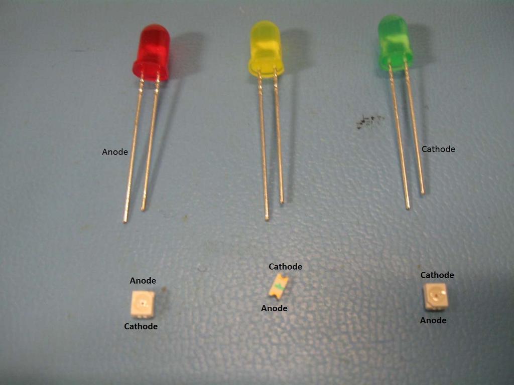
9 Terms and Definitions (Continued) IC Integrated circuit i.e.; can be an amplifier, buffer, or oscillator Transformer Changes voltage to a higher or lower level than what was applied. If voltage goes up, current goes down. If voltage goes down, current goes up LED A device with one PN junction that only allows current to flow in one direction and produces light of various colors (not used for rectification) Cathode The end of the diode that has the bar on it (ground side). It is the negative side of the diode Anode The positive end of the diode Emitter The part of the transistor that goes to the ground side of the circuit. It emits electrons
10 Terms and Definitions (Continued) Base The part of the transistor that controls the state of the transistor Collector The part of the transistor that collects the electrons emitted by the emitter SMD Surface Mount Device Leaded Part Electronic parts with leads to attach the part to the circuit PCB Printed circuit board PIV (Peak Inverse Voltage) The highest reverse voltage a diode or transistor can handle without damage Fuse Ratings 250V/5A the 250 is the arc over voltage once the fuse is blown, 5 amps is the current that will cause the fuse to open
11 Terms and Definitions (Continued) Units of measurement T (Tera) 1,000,000,000, G (Giga) 1,000,000, M (Mega) 1,000, K (Kilo) 1, Units 1 0 m (milli) u (micro) n (Nano) p (Pico)
12 Terms and Definitions (Continued) E = Voltage R = Resistance I = Current W = Power Half Wave Rectification Uses half of the AC wave to produce DC voltage Full Wave Rectification Uses the full AC wave to produce DC voltage (Smoother DC output than Half Wave rectification)
13
14 Drawing the Schematic Start on the upper left, work to the right and then down Number your pages Name all bus lines, and keep them constant throughout the schematic Show the page number for all bus lines, showing all pages that line is located on Number all components R1, R2, C1, C2, etc. Use arrows to show data/current flow on and off the pages Keep it neat!

15 Mark your inputs and outputs

16 Make NOTES about important things
17 Show page numbers for all inputs and outputs
18 Label all bus lines
19 Number all of the components
20 Label all signal lines
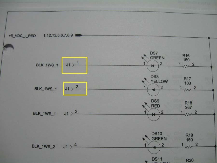
21 Label all connectors

22 Electrolytic Capacitor markings

23 Diode markings
24 Surface Mount vs. Leaded parts Surface mount parts are smaller than the same part with leads Surface mount parts have the same values as the leaded parts Surface mount parts are readily available, and cheap Surface mount parts were meant to be on a circuit board, therefore can be hard to work with Leaded parts were meant to be used for point to point wiring
25 LED s
26 LEDs vs. Incandescent bulbs Lower current Operate cooler Can give the look of fluorescent lighting (using white LEDs) Can give the look of incandescent lighting (using Golden LEDs) Easier to hide a Surface Mount Device (SMD) LED in a building than an incandescent bulb
27 Resistor Color Codes for Carbon Composite Resistors 0 = Black 6 = Blue 1 = Brown 7 = Violet 2 = Red 8 = Gray 3 = Orange 9 = White 4 = Yellow 5% = Gold 5 = Green 10% = Silver The third color band indicates the number of zeroes to be added after figures given by the first two color bands. If the third color band is Gold, multiply by 0.1, and if Silver multiply by Don t confuse this with the fourth color band that indicates tolerance. Thus, a resistor marked with Blue Red Gold Gold has a resistance of 6.2 ohms and a tolerance of 5%. How to remember the color codes Bad Boys Rape Our Young Girls But Violet Gives Willingly

28 Carbon Composite Resistors

29 Metal Film Resistors

30 Fuse holders
31 Wiring for the layout Assign two colors for track bus for each power district Assign two colors for the turn out controls Assign colors for any thing else that you will have wired on the layout Stay with this color scheme and write it down!!!!!! Never use anything smaller that 28 gauge wire for feeder wires from the track bus to the rails And connect them every six feet
32 Wiring for the layout (Continued) Make your wiring neat. You will have to troubleshoot it sometime in the future (Use cheap metal shower hooks to run the wiring through) Draw a schematic of the railroad for when you have to troubleshoot it in the future Keep the cab bus and track bus as far as possible for each other. If they have to cross each other, do it at a 90 degree angle Mark your power district wiring at both ends For long track bus runs (over 20 feet) twist the wire three turns per foot and install a snubber (47 to 100 ohm resistor and a capacitor that is 0.1 uf 50 V)

33 Ohms Law for DC Circuits
34 Ohms law Simplified Eagles Rangers Indians
35 Before we get started with Ohm s Law Measure your track voltage and document it my track voltage is 14.2 volts AC Measure the light common for the decoder I measured light common to one of the function outputs on a Sound Traxx Tsunami and got 13.4 volts DC If you are going to use the half wave method, measure the function out put to one of the rail to the decoder on the Tsunami I got 6.5 volts DC
36 Lets put Ohms law to work The Knowns KNOWN You are using a pair of 1.5 volt bulbs for your headlights. KNOWN You are using DCC and your track voltage is 14.2 volts AC (actually a square wave) KNOWN The Lighting Common output (blue wire) of your decoder is 13.4 volts DC (the function outputs are ground) KNOWN Function output to one rail is 6.5 volts DC
37 Lets put Ohms law to work The Unknowns UNKNOWN What is the current of the bulb UNKNOWN What value resistor do you need UNKNOWN What wattage resistor do you need
38 Some things to think about before you start Am I going to use full wave rectification or half wave rectification, and what is the difference? Using the full wave method, you have to drop all the voltage out of the lighting common output Using the half wave method, you only have to drop about half the voltage of lightning common (go to one side of track power) Am I going to wire the bulbs in series or parallel and what is the difference? In series you drop voltage across both bulb (3V) and the current through both bulbs are the same as one bulb In parallel you drop voltage across each bulb (1.5V) and the current is now the combination of both bulbs How much space do I have in the locomotive?
39 Here is how I do my lighting and why Put the bulbs in series The more voltage you can drop with the bulbs, the less you have to drop over the resistor The less voltage you have to drop with the resistor, the smaller the wattage resistor you can use Use the half wave method means less voltage to drop, ( 6.5 Volts vs Volts) means smaller wattage resister
40 Finding out the Unknowns Using two 1.5 volt batteries in series, connect the red battery lead to the bulbs that are in series, connect the other bulb lead to your voltmeter red lead. With the voltmeter in the Current mode, connect the black lead of the voltmeter to the battery black lead. This will give you the current needed by the bulbs. Disconnect the batteries after you make your measurement. You can get a battery holders from Radio Shack that holds two 1.5 volt batteries. Remember, lighting common is the positive side of the function output
41 Now back to Lets put Ohms law to work We found out our bulbs in series drew.016 Amps We know our Lighting common voltage is 13.4 volts We know that the two bulbs in series are going to drop 3 volts at.016 Amps Now we can put Ohms Law to work!
42 Putting Ohms law to work Full Wave Bulb voltage = 3 volts (Two 1.5 volt bulbs in series) Full Wave voltage is 13.4 volts (function output to lighting common) That means we have to drop 10.4 volts across the resistor Here we go E = Voltage, I = Current, R = resistance E / I = R E = 10.4 V, I =.016, R =? 10.4 V/.016 I = Ohms Standard value resistor will be 681 Ohms. You could use two 1.30 K ohm, 1/8 W resistors in parallel to get 650 ohms Never go a smaller value resistor or you will be replacing the bulbs
43 Putting Ohms law to work Full Wave To solve for the wattage needed for the dropping resistor, use the power formula E X I = W E = Voltage, I = Current, W = Power 10.4 V X.016 A =.166 W In this case, use an 1/4 watt resistor.
44 Putting Ohms law to work Half Wave Bulb voltage = 3 volts (Two 1.5 volt bulbs in series) Half Wave voltage is 6.5 volts (function output to one side of track power) That means we have to drop 3.5 volts across the resistor Here we go E = Voltage, I = Current, R = Resistance E = 3.5 V, I =.016, R =? 3.5 V/.016 I = Ohms Standard value resistor will be 221 Ohms. You could use two 442 ohm, 1/8 W resistors in parallel to get 221 ohms Never go a smaller value resistor or you will be replacing the bulbs
45 Putting Ohms law to work Half Wave To solve for the wattage needed for the dropping resistor, use the power formula E X I = W E = Voltage, I = Current, W = Power 3.5 V X.016 A =.056 W In this case, use an 1/8 watt resistor. I use 1/4 watt resistors in all my installations unless it requires a larger wattage resistor
46 Resistors in series vs. parallel Resistors in series add the resistance of the all the resistors (two 500 ohm resistors equal 1000 ohms). They also add the ability to dissipate more heat. Resistors in parallel lower the resistance of all resistors (two 500 ohm resistors equal 250 ohms). They also add the ability to dissipate more heat.
47 Wire Size vs. Maximum Current Capability Max Voltage drop for the wire should be no more than 3% (14 V X 3% =.42 V) Length 5 Amps 10 Amps 15 feet 16 AWG 12 AWG 20 feet 14 AWG 12 AWG 25 feet 14 AWG 10 AWG 30 feet 12 AWG 10 AWG 40 feet 12 AWG 8 AWG 50 feet 10 AWG 8 AWG 60 feet 10 AWG 6 AWG 70 feet 10 AWG 6 AWG 80 Feet 8 AWG 6 AWG Feeder wires no less than 28 gauge every 6 feet keep them short as possible!! ALWAYS use a bigger wire for track bus than you think you need!!
48 Nice things to have Tools and stuff A good digital volt meter with current and diode test function 25 watt soldering iron Sponge for cleaning the solder iron tip Rosin core solder NEVER use acid core solder Flux Wire strippers 30 to 22 gauge and 22 to 10 gauge Side cutters Round nose pliers Needle nose pliers Heat shrink insulation various sizes Alcohol Rubbing not drinking!!!
49 Questions? Thanks for attending my workshop on Basic Electronics for Model Railroaders. If you have questions after you leave the convention, please feel free to contact me. This Power Point Presentation is on my web site under Modeling /DCC Tips then Modeling Tips Cell: if I don t answer, leave a message and I will call you back. E mail: b n ferrco@cfl.rr.com Web Site: b n ferrco.com
LED ROBOT BLINKER KIT
 LED ROBOT BLINKER KIT MODEL K-17 Assembly and Instruction Manual Elenco Electronics, Inc. Copyright 1989, 1998 Elenco Electronics, Inc. Revised 2001 REV-J 753217 PARTS LIST If any parts are missing or
FCC Technician License Course
 FCC Technician License Course 2014-2018 FCC Element 2 Technician Class Question Pool Presented by: Tamiami Amateur Radio Club (TARC) WELCOME To the SECOND of 4, 3-hour classes presented by TARC to prepare
LED ROBOT BLINKER KIT
 LED ROBOT BLINKER KIT MODEL K-17 Assembly and Instruction Manual ELENCO Copyright 2016, 1998 by ELENCO Electronics, Inc. All rights reserved. Revised 2013 REV-P 753217 No part of this book shall be reproduced
Assembly Instructions
 Assembly Instructions For the SSQ-2F 3.1 MHz Rife Controller Board Kit v1.41 Manual v1.00 2012 by Ralph Hartwell Spectrotek Services GENERAL ASSEMBLY INSTRUCTIONS Arrange for a clean work surface with
EASY BUILD TIMER KIT TEACHING RESOURCES. Version 2.0 LEARN ABOUT SIMPLE TIMING CIRCUITS WITH THIS
 TEACHING RESOURCES SCHEMES OF WORK DEVELOPING A SPECIFICATION COMPONENT FACTSHEETS HOW TO SOLDER GUIDE LEARN ABOUT SIMPLE TIMING CIRCUITS WITH THIS EASY BUILD TIMER KIT Version 2.0 Index of Sheets TEACHING
AC/DC ELECTRONICS LABORATORY
 Includes Teacher's Notes and Typical Experiment Results Instruction Manual and Experiment Guide for the PASCO scientific Model EM-8656 012-05892A 1/96 AC/DC ELECTRONICS LABORATORY 1995 PASCO scientific
DELUXE STEREO AMPLIFIER KIT
 TEACHING RESOURCES SCHEMES OF WORK DEVELOPING A SPECIFICATION COMPONENT FACTSHEETS HOW TO SOLDER GUIDE CREATE YOUR OWN SPEAKER DOCK WITH THIS DELUXE STEREO AMPLIFIER KIT Version 2.0 Index of Sheets TEACHING
AM RADIO KIT MODEL AM-780K. Assembly and Instruction Manual
 AM RADIO KIT MODEL AM-780K Assembly and Instruction Manual Elenco Electronics, Inc. Copyright 2007, 1999 by Elenco Electronics, Inc. All rights reserved. Revised 2007 REV-F 753108 No part of this book
SUBELEMENT T6 Electrical components: semiconductors; circuit diagrams; component functions 4 Exam Questions - 4 Groups
 SUBELEMENT T6 Electrical components: semiconductors; circuit diagrams; component functions 4 Exam Questions - 4 Groups 1 T6A Electrical components: fixed and variable resistors; capacitors and inductors;
Voltage Current V I. Resistors are colour-coded: the number of Ohms resistance is indicated by a series of coloured bands on the resistor.
 Introduction to Electronics Part 1: Some Basic Ideas and omponents urrent, Voltage and esistance urrent is a measure of the rate of flow of charge (unit: the Amp). Voltage is a measure of the force with
Main improvements are increased number of LEDs and therefore better temperature indication with one Celsius degree increments.
 LED Thermometer V2 (Fahrenheit/Celsius/±1 ) PART NO. 2244754 After completing this great starter kit, users will have a nice interactive LED thermometer. You will learn one principle how temperature can
EGR Laboratory 1 - Introduction to Circuit Analysis
 EGR 215 Laboratory 1 Introduction to Circuit Analysis Authors D. Wilson, R.D. Christie, W.R. Lynes, K.F. Böhringer, M. Ostendorf of the University of Washington Objectives At the end of this lab, you will
DARK ACTIVATED COLOUR CHANGING NIGHT LIGHT KIT
 TEACHING RESOURCES SCHEMES OF WORK DEVELOPING A SPECIFICATION COMPONENT FACTSHEETS HOW TO SOLDER GUIDE CREATE SOOTHING LIGHTING EFFECTS WITH THIS DARK ACTIVATED COLOUR CHANGING NIGHT LIGHT KIT Version
FCC Technician License Course
 FCC Technician License Course 2018-2022 FCC Element 2 Technician Class Question Pool Presented by: Tamiami Amateur Radio Club (TARC) WELCOME To the SECOND of 3, 4-hour classes presented by TARC to prepare
AM RADIO KIT MODEL AM-780K. Assembly and Instruction Manual ELENCO
 AM-780K_REV-K_050416.qxp_AM-780K_REV-K_050416 5/10/16 8:13 AM Page 1 AM RADIO KIT MODEL AM-780K Assembly and Instruction Manual ELENCO Copyright 2016, 1999 by Elenco Electronics, Inc. All rights reserved.
Introduction. Inductors in AC Circuits.
 Module 3 AC Theory What you ll learn in Module 3. Section 3.1 Electromagnetic Induction. Magnetic Fields around Conductors. The Solenoid. Section 3.2 Inductance & Back e.m.f. The Unit of Inductance. Factors
POWER SUPPLY KIT MODEL XP-720K. Assembly Manual ELENCO
 POWER SUPPLY KIT MODEL XP-720K Assembly Manual ELENCO Copyright 2012, 1998 by ELENCO All rights reserved. Revised 2012 REV-G 753269 No part of this book shall be reproduced by any means; electronic, photocopying,
PAT-4 POWER SUPPLY ASSEMBLY MANUAL Rev B Version
 PAT-4 POWER SUPPLY ASSEMBLY MANUAL Rev B Version 2013 AkitikA, LLC All rights reserved Revision Bp01 November 3, 2013 Page 1 of 16 Table of Contents Table of Contents... 2 Table of Figures... 2 Section
B EE Laboratory 1 - Introduction to Circuit Analysis
 Page 1 B EE 215 Introduction to Circuit Analysis Authors D. Wilson, R.D. Christie, W.R. Lynes, K.F. Böhringer, M. Ostendorf Objectives At the end of this lab, you will be able to: Check continuity with
BEST BMET CBET STUDY GUIDE MODULE ONE
 BEST BMET CBET STUDY GUIDE MODULE ONE 1 OCTOBER, 2008 1. The phase relation for pure capacitance is a. current leads voltage by 90 degrees b. current leads voltage by 180 degrees c. current lags voltage
BASIC ELECTRONICS PROF. T.S. NATARAJAN DEPT OF PHYSICS IIT MADRAS LECTURE-2 ELECTRONIC DEVICES -1 RESISTOR, IDEAL SOURCE VOLTAGE & CAPACITOR
 BASIC ELECTRONICS PROF. T.S. NATARAJAN DEPT OF PHYSICS IIT MADRAS LECTURE-2 ELECTRONIC DEVICES -1 RESISTOR, IDEAL SOURCE VOLTAGE & CAPACITOR In the last lecture we saw the importance of learning about
Amplifier, Product Design
 Amplifier, Product Design Choose one component from the amplifier circuit and investigate technical, theory and mathematical information related to your chosen component. This work will be completed over
Pre-Laboratory Assignment
 Measurement of Electrical Resistance and Ohm's Law PreLaboratory Assignment Read carefully the entire description of the laboratory and answer the following questions based upon the material contained
I N T R O D U C T I O N T O E L E C T R O N I C R E S T O R A T I O N
 I N T R O D U C T I O N T O E L E C T R O N I C R E S T O R A T I O N This is a brief introduction to the various components used in vintage equipments. The basic function of each component is explained,
Easy Transmitter. Support ETX_REV5_Manual V2.7 Revised
 Easy Transmitter Introduction The Easy Transmitter kit from qrpkits.com provides a basic, crystal controlled transmitter with VXO tuning to provide a small tuning range around the crystal frequency. It
Micro USB Lamp Kit TEACHING RESOURCES. Version 2.1 DESIGN A STYLISH LAMP WITH THIS
 TEACHING RESOURCES SCHEMES OF WORK DEVELOPING A SPECIFICATION COMPONENT FACTSHEETS HOW TO SOLDER GUIDE DESIGN A STYLISH LAMP WITH THIS Micro USB Lamp Kit Version 2.1 Index of Sheets TEACHING RESOURCES
SOLDER PRACTICE KIT MODEL SP-3B. Assembly and Instruction Manual
 SOLDER PRACTICE KIT MODEL SP-3B 99 Washington Street Melrose, MA 02176 Phone 781-665-1400 Toll Free 1-800-517-8431 Visit us at www.testequipmentdepot.com Assembly and Instruction Manual Elenco Electronics,
Introduction to Electronics. Dr. Lynn Fuller
 ROCHESTER INSTITUTE OF TECHNOLOGY MICROELECTRONIC ENGINEERING Introduction to Electronics Dr. Lynn Fuller Webpage: http://www.rit.edu/~lffeee 82 Lomb Memorial Drive Rochester, NY 14623-5604 Tel (585) 475-2035
RESISTANCE & OHM S LAW (PART I
 RESISTANCE & OHM S LAW (PART I and II) Objectives: To understand the relationship between potential and current in a resistor and to verify Ohm s Law. To understand the relationship between potential and
Electrical Fundamentals and Basic Components Chapters T2, T3, G4
 Electrical Fundamentals and Basic Components Chapters T2, T3, G4 Some Basic Math, Electrical Fundamentals, AC Power, The Basics of Basic Components, A Little More Component Detail, Reactance and Impedance
Line-Following Robot
 1 Line-Following Robot Printed Circuit Board Assembly Jeffrey La Favre October 5, 2014 After you have learned to solder, you are ready to start the assembly of your robot. The assembly will be divided
IR add-on module circuit board assembly - Jeffrey La Favre January 27, 2015
 IR add-on module circuit board assembly - Jeffrey La Favre January 27, 2015 1 2 For the main circuits of the line following robot you soldered electronic components on a printed circuit board (PCB). The
fuzzbox If you are asked to imagine the sound soldering your way to distortion how to make a diy by rob cruickshank photography by adam coish
 diy how to make a fuzzbox soldering your way to distortion by rob cruickshank photography by adam coish If you are asked to imagine the sound of an electric guitar, there s a good chance that the sound
Experiment 3 Ohm s Law
 Experiment 3 Ohm s Law The goals of Experiment 3 are: To identify resistors based upon their color code. To construct a two-resistor circuit using proper wiring techniques. To measure the DC voltages and
Ohm's Law and DC Circuits
 Physics Lab II Ohm s Law Name: Partner: Partner: Partner: Ohm's Law and DC Circuits EQUIPMENT NEEDED: Circuits Experiment Board Two Dcell Batteries Wire leads Multimeter 100, 330, 560, 1k, 10k, 100k, 220k
SOLDER PRACTICE KIT MODEL SP-1A. Assembly and Instruction Manual
 SOLDER PRACTICE KIT MODEL SP-1A Assembly and Instruction Manual Copyright 2018, 1994 by ELENCO Electronics, Inc. All rights reserved. Revised 2018 REV-V No part of this book shall be reproduced by any
Assembly Instructions
 Assembly Instructions for the PA3 v2.0 Amplifier Kit PA3 Amplifier shown mounted on HS2 Heat Sink (The HS2 shown here is not included with this kit.) 27 February 2016 2013-2016 by Ralph Hartwell Spectrotek
Workshop Part Identification Lecture N I A G A R A C O L L E G E T E C H N O L O G Y D E P T.
 Workshop Part Identification Lecture N I A G A R A C O L L E G E T E C H N O L O G Y D E P T. Identifying Resistors Resistors can be either fixed or variable. The variable kind are called potentiometers
Semiconductors, ICs and Digital Fundamentals
 Semiconductors, ICs and Digital Fundamentals The Diode The semiconductor phenomena. Diode performance with ac and dc currents. Diode types: General purpose LED Zener The Diode The semiconductor phenomena
Introduction 1. Download socket (the cable plugs in here so that the GENIE microcontroller can talk to the computer)
") Introduction 1 Welcome to the magical world of GENIE! The project board is ideal when you want to add intelligence to other design or electronics projects. Simply wire up your inputs and outputs and away
Introduction 1 Welcome to the magical world of GENIE! The project board is ideal when you want to add intelligence to other design or electronics projects. Simply wire up your inputs and outputs and away
THE RING RESONATOR (K-975)
") THE RING RESONATOR (K-975) OUTPUT BOOST The Ring Resonator An Octave Up Fuzz Modkitsdiy.com 9 VDC CENTER (-) ADAPTER TO AMP IN FROM GUITAR OUT Unplug when not in use to save battery life. Use these instructions
THE RING RESONATOR (K-975) OUTPUT BOOST The Ring Resonator An Octave Up Fuzz Modkitsdiy.com 9 VDC CENTER (-) ADAPTER TO AMP IN FROM GUITAR OUT Unplug when not in use to save battery life. Use these instructions
YAP BOX KIT MODEL K-22A YAP BOX SIX EXCITING SOUNDS. Assembly and Instruction Manual
 YAP BOX KIT MODEL K-22A YAP BOX SIX EXCITING SOUNDS Assembly and Instruction Manual Elenco Electronics, Inc. Copyright 2009, 1989 by Elenco Electronics, Inc. All rights reserved. Revised 2009 REV-H 753222
Basic Electronics & Theory Lesson 5
 5.1 Metric Prefixes Metric prefixes you'll need to know... 1 Giga (G) = 1 billion = 1,000,000,000 1 Mega (M) = 1 million = 1,000,000 1 kilo (k) = 1 thousand = 1,000 1 centi (c) = 1 one-hundredth = 0.01
Bill of Materials: General Purpose Alarm, Pulsed PART NO
 General Purpose Alarm, Pulsed PART NO. 2190207 I hate alarms that sound continuously - unless they are smoke alarms. Smoke alarms should be annoying, but others should not. I wanted an alarm for a function
THE THUNDERDRIVE (K-950)
") THE THUNDERDRIVE (K-950) OUTPUT DISTORTION Unplug when not in use to save battery life. TO AMP IN The Thunderdrive Modkitsdiy.com FROM GUITAR OUT Use these instructions to learn: How to build an effects
THE THUNDERDRIVE (K-950) OUTPUT DISTORTION Unplug when not in use to save battery life. TO AMP IN The Thunderdrive Modkitsdiy.com FROM GUITAR OUT Use these instructions to learn: How to build an effects
EET140/3 ELECTRIC CIRCUIT I
 SCHOOL OF ELECTRICAL SYSTEM ENGINEERING UNIVERSITI MALAYSIA PERLIS EET140/3 ELECTRIC CIRCUIT I MODULE 1 PART I: INTRODUCTION TO BASIC LABORATORY EQUIPMENT PART II: OHM S LAW PART III: SERIES PARALEL CIRCUIT
ELECTRIC Circuits Test
 ELECTRIC Circuits Test Name: /50 Multiple Choice (1 mark each) ( 13 marks) 1. Circle the best answer for each of the multiple choice questions below: Quantity measured Units used 1 -- potential difference
Circuit LED 1 LED 2 A on or off on or off B on or off on or off C on or off on or off
 Cornerstone Electronics Technology and Robotics Week 8 Chapter 3, Introduction to Basic Electrical Circuit Materials Continued Administration: o Prayer o Turn in quiz Review LED s: o Wire the following
LOGIC PROBE KIT MODEL LP-525K. Assembly and Instruction Manual ELENCO
 LOGIC PROBE KIT MODEL LP-525K Assembly and Instruction Manual ELENCO Copyright 2013, 1994 by Elenco Electronics, Inc. All rights reserved. Revised 2013 REV-J 753241 No part of this book shall be reproduced
University of Technology, Jamaica School of Engineering. Electrical Workshop Notes On Electrical components
 University of Technology, Jamaica School of Engineering Electrical Workshop Notes On Electrical components Resistors Resistors are fundamental components in electronic circuits. A resistor is constructed
Pre-certification Electronics Questions. Answer the following with the MOST CORRECT answer.
 Electronics Questions Answer the following with the MOST CORRECT answer. 1. The cathode end terminal of a semiconductor diode can be identified by: a. the negative sign marked on the case b. a circular
Experiment 1: Circuits Experiment Board
 01205892C AC/DC Electronics Laboratory Experiment 1: Circuits Experiment Board EQUIPMENT NEEDED: AC/DC Electronics Lab Board: Wire Leads Dcell Battery Graph Paper Purpose The purpose of this lab is to
AC-DC-DCC. AC-DC-DCC4_blue.ppt x 8/1/2012 Slide 1
 AC-DC-DCC4_blue.ppt x 8/1/2012 Slide 1 NOTE This Clinic Is Highly Animated With Picture Overlays And Graphics. PDF and Other Versions May Look Contaminated. AC-DC-DCC4_blue.ppt x 8/1/2012 Slide 2 AC-DC-DCC
DIODE / TRANSISTOR TESTER KIT
 DIODE / TRANSISTOR TESTER KIT MODEL DT-100K Assembly and Instruction Manual Elenco Electronics, Inc. Copyright 1988 Elenco Electronics, Inc. Revised 2002 REV-K 753110 DT-100 PARTS LIST If you are a student,
Assembly and User Guide
 Assembly and User Guide AtariPunkr is an adjustable stepped tone generator. AtariPunkr provides hours of fun everyone! Powered by: 9V Battery Outputs: Mylar Speaker (Included) Stereo Output (3.5mm Jack)
SOLDER PRACTICE KIT MODEL SP-3B. Assembly and Instruction Manual ELENCO
 SOLDER PRACTICE KIT MODEL SP-3B Assembly and Instruction Manual ELENCO Copyright 2017, 2001 by Elenco Electronics, Inc. All rights reserved. Revised 2012 REV-K No part of this book shall be reproduced
Technician Licensing Class T6
 Technician Licensing Class T6 Amateur Radio Course Monroe EMS Building Monroe, Utah January 11/18, 2014 January 22, 2014 Testing Session Valid dates: July 1, 2010 June 30, 2014 Amateur Radio Technician
AC/DC POWER SUPPLY KIT
 AC/DC POWER SUPPLY KIT MODEL K-11 Assembly and Instruction Manual ELENCO Copyright 2016, 1989 by ELENCO All rights reserved. Revised 2016 REV-O 753211 No part of this book shall be reproduced by any means;
Building a Bitx20 Version 3
 Building a Bitx20 Version 3 The board can be broken into sections and then built and tested one section at a time. This will make troubleshooting easier as any problems will be confined to one small section.
AM/FM RADIO KIT MODEL AM/FM-108CK SUPERHET RADIO CONTAINS TWO SEPARATE AUDIO SYSTEMS: IC AND TRANSISTOR. Assembly and Instruction Manual ELENCO
 AM/FM RADIO KIT MODEL AM/FM-108CK SUPERHET RADIO CONTAINS TWO SEPARATE AUDIO SYSTEMS: IC AND TRANSISTOR Assembly and Instruction Manual ELENCO Copyright 2012 by ELENCO All rights reserved. 753510 No part
Programmable Timer Teaching Notes Issue 1.2
 Teaching Notes Issue 1.2 Product information: www.kitronik.co.uk/quicklinks/2121/ TEACHER Programmable Timer Index of sheets Introduction Schemes of work Answers The Design Process The Design Brief Investigation
HANDS-ON LAB INSTRUCTION SHEETS MODULE
 HANDS-ON LAB INSTRUCTION SHEETS MODULE 1 MEASURING RESISTANCE AND VOLTAGE NOTES: 1) Each student will be assigned to a unique Lab Equipment number MS01-MS30 which will match to a Tool Kit and a Radio Shack
2007 The McGraw-Hill Companies, Inc. All rights reserved.
 Chapter 2 Resistors Topics Covered in Chapter 2 2-1: Types of Resistors 2-2: Resistor Color Coding 2-3: Variable Resistors 2-4: Rheostats and Potentiometers 2-5: Power Ratings of Resistors 2-6: Resistor
Simple LFO Features. 2. Application. 3. Description. Simple and easy to build LFO module for Analog Synthesizers.
 Simple LFO. Simple and easy to build LFO module for Analog Synthesizers.. Features Square and Triangle waveforms (90 phase shifted) Dual range frequencies Frequency ranges from under Hz up to several khz
Pacific Antenna Easy TR Switch
 Pacific Antenna Easy TR Switch Kit Description The Easy TR Switch is an RF sensing circuit with a double pole double throw relay that can be used to automatically switch an antenna between a separate receiver
HANDS-ON LAB INSTRUCTION SHEET MODULE 3 CAPACITORS, TIME CONSTANTS AND TRANSISTOR GAIN
 HANDS-ON LAB INSTRUCTION SHEET MODULE 3 CAPACITORS, TIME CONSTANTS AND TRANSISTOR GAIN NOTES: 1) To conserve the life of the Multimeter s 9 volt battery, be sure to turn the meter off if not in use for
EECE 2413 Electronics Laboratory
 EECE 2413 Electronics Laboratory Lab #2: Diode Circuits Goals In this lab you will become familiar with several different types of pn-junction diodes. These include silicon and germanium junction diodes,
II. Experimental Procedure
 Ph 122 July 27, 2006 Ohm's Law http://www.physics.sfsu.edu/~manuals/ph122/ I. Theory In this lab we will make detailed measurements on one resistor to see if it obeys Ohm's law. We will also verify the
DIODE / TRANSISTOR TESTER KIT
 DIODE / TRANSISTOR TESTER KIT MODEL DT-100K 99 Washington Street Melrose, MA 02176 Phone 781-665-1400 Toll Free 1-800-517-8431 Visit us at www.testequipmentdepot.com Assembly and Instruction Manual Elenco
LM2412 Monolithic Triple 2.8 ns CRT Driver
 Monolithic Triple 2.8 ns CRT Driver General Description The is an integrated high voltage CRT driver circuit designed for use in high resolution color monitor applications. The IC contains three high input
THE AGGRESSOR (K-995)
") THE AGGRESSOR (K-99) TONE VOLUME DISTORTION MID-SHIFT SWITCH LED The Aggressor Distortion Pedal Modkitsdiy.com 9 VDC CENTER (-) ADAPTER TO AMP IN FROM GUITAR OUT Unplug when not in use to save battery
THE AGGRESSOR (K-99) TONE VOLUME DISTORTION MID-SHIFT SWITCH LED The Aggressor Distortion Pedal Modkitsdiy.com 9 VDC CENTER (-) ADAPTER TO AMP IN FROM GUITAR OUT Unplug when not in use to save battery
Switcher Assembly guide. Switcher Assembly guide 1. Soldering. 2. Switcher3 vs Switcher2. 3. PCB split.
 Safety warning The kits are main powered and use potentially lethal voltages. Under no circumstance should someone undertake the realisation of a kit unless he has full knowledge about safely handling
Electronics & Control
 Electronics & Control Analogue Electronics Introduction By the end of this unit you should be able to: Know the difference between a series and parallel circuit Measure voltage in a series circuit Measure
Pacific Antenna - Easy TR Switch
 Pacific Antenna - Easy TR Switch Kit Description The Easy TR Switch is an RF sensing switch that can be used to switch an antenna between a receiver and transmitter. It also has a second switched pair
TEACHING RESOURCES SCHEMES OF WORK DEVELOPING A SPECIFICATION COMPONENT FACTSHEETS HOW TO SOLDER GUIDE GET IN TUNE WITH THIS FM RADIO KIT. Version 2.
 TEACHING RESOURCES SCHEMES OF WORK DEVELOPING A SPECIFICATION COMPONENT FACTSHEETS HOW TO SOLDER GUIDE GET IN TUNE WITH THIS FM RADIO KIT Version 2.2 Index of Sheets TEACHING RESOURCES Index of Sheets
Electronic Components. Identification of components and handling precautions to protect them from damage due to electrostatic discharge
 Electronic Components Identification of components and handling precautions to protect them from damage due to electrostatic discharge 1 Passive Components Resistors Capacitors Inductors Diodes Interface
The answer is R= 471 ohms. So we can use a 470 ohm or the next higher one, a 560 ohm.
 Introducing Resistors & LED s P a g e 1 Resistors are used to adjust the voltage and current in a circuit. The higher the resistance value, the more electrons it blocks. Thus, higher resistance will lower
FM RADIO KIT ESSENTIAL INFORMATION. Version 2.0 GET IN TUNE WITH THIS
 ESSENTIAL INFORMATION BUILD INSTRUCTIONS CHECKING YOUR PCB & FAULT-FINDING MECHANICAL DETAILS HOW THE KIT WORKS GET IN TUNE WITH THIS FM RADIO KIT Version 2.0 Build Instructions Before you start, take
SOLDER PRACTICE KIT MODEL SP-1A
 99 Washington Street Melrose, MA 02176 Phone 781-665-1400 Toll Free 1-800-517-8431 Visit us at www.testequipmentdepot.com SOLDER PRACTICE KIT MODEL SP-1A Assembly and Instruction Manual Elenco Electronics,
Technician Licensing Class
 Technician Licensing Class Go Picture Presented These! by Amateur Radio Technician Class Element 2 Course Presentation ELEMENT 2 SUB-ELEMENTS (Groupings) About Ham Radio Call Signs Control Mind the Rules
2. Solve this binary equation. Answer in a decimal number form = A. 42 B. 54 C. 15 D
 Electronics Practice Test By David Scott, Manfred Brancard and Gary Troutman 1. A few capacitors are in parallel. Calculate the total capacitance. The capacitor values are 1uF, 2uF, 3uF, and 4uF. The total
SCHEMATIC OF GRAYMARK 808 POWERED BREADBOARD
 SCHEMATIC OF GRAYMARK 808 POWERED BREADBOARD 1a white SW1 white 2a TP1 blue TP2 black blue TP3 TP4 yellow TP5 yellow TP6 4 3 8 7 + D1 D2 D5 D6 C1 R1 TP8 Q1 R3 TP12 2 TP18 U2-0-15V C8 9 C2 + TP15 C5 R12
N3ZI Kits General Coverage Receiver, Assembly & Operations Manual (For Jun 2011 PCB ) Version 3.33, Jan 2012
 Version 3.33, Jan 2012") N3ZI Kits General Coverage Receiver, Assembly & Operations Manual (For Jun 2011 PCB ) Version 3.33, Jan 2012 Thank you for purchasing my general coverage receiver kit. You can use the photo above as a
N3ZI Kits General Coverage Receiver, Assembly & Operations Manual (For Jun 2011 PCB ) Version 3.33, Jan 2012 Thank you for purchasing my general coverage receiver kit. You can use the photo above as a
OHM'S LAW AND RESISTANCE NETWORKS OBJECT
 17 E7 E7.1 OHM'S LAW AND RESISTANCE NETWORKS OBJECT The objects of this experiment are to determine the voltage-current relationship for a resistor and to verify the series and parallel resistance formulae.
SUBELEMENT T5 Electrical principles: math for electronics; electronic principles; Ohm s Law 4 Exam Questions - 4 Groups
 SUBELEMENT T5 Electrical principles: math for electronics; electronic principles; Ohm s Law 4 Exam Questions - 4 Groups 1 T5A Electrical principles, units, and terms: current and voltage; conductors and
ELECTRIC CIRCUITS AND ELECTRONICS
 Circuitos eléctricos y electrónicos ELECTRIC CIRCUITS AND ELECTRONICS Technology, programming and robotics II Electric Circuitos circuits eléctricos and y electronics electrónicos AN ELECTRICAL CIRCUIT
RadiØKit Μ CW HAM RADIO TRANSCEIVER KIT. Assembly and operating manual
 RadiØKit-120 20Μ CW HAM RADIO TRANSCEIVER KIT Assembly and operating manual Boreiou Ipirou 78 Kolonos Athens- Greece - 10444 Tel: 210.5150527 210.5132673 www.freebytes.com Thank you for buying RadiØKit-1,
Multimeter Definition
 Multimeter Definition A multimeter is a devise used to measure voltage, resistance and current in electronics & electrical equipment It is also used to test continuity between to 2 points to verify if
Time of Arrival Radio Direction Finder.
 Time of Arrival Radio Direction Finder. Time of arrival (TOA) RDF units are simple and very useful. Various designs have been distributed over the years, and here is another one. This Kit Developed by
Electronics 1. Voltage/Current Resistors Capacitors Inductors Transistors
 Electronics 1 Voltage/Current Resistors Capacitors Inductors Transistors Voltage and Current Simple circuit a battery pushes some electrons around the circuit how many per second? Water The easiest way
2.00AJ / 16.00AJ Exploring Sea, Space, & Earth: Fundamentals of Engineering Design Spring 2009
 MIT OpenCourseWare http://ocw.mit.edu 2.00AJ / 16.00AJ Exploring Sea, Space, & Earth: Fundamentals of Engineering Design Spring 2009 For information about citing these materials or our Terms of Use, visit:
Experiment 2. Ohm s Law. Become familiar with the use of a digital voltmeter and a digital ammeter to measure DC voltage and current.
 Experiment 2 Ohm s Law 2.1 Objectives Become familiar with the use of a digital voltmeter and a digital ammeter to measure DC voltage and current. Construct a circuit using resistors, wires and a breadboard
V (in volts) = voltage applied to the circuit, I (in amperes) = current flowing in the circuit, R (in ohms) = resistance of the circuit.
 = voltage applied to the circuit, I (in amperes) = current flowing in the circuit, R (in ohms) = resistance of the circuit.") OHM S LW OBJECTIES: PRT : 1) Become familiar with the use of ammeters and voltmeters to measure DC voltage and current. 2) Learn to use wires and a breadboard to build circuits from a circuit diagram.
OHM S LW OBJECTIES: PRT : 1) Become familiar with the use of ammeters and voltmeters to measure DC voltage and current. 2) Learn to use wires and a breadboard to build circuits from a circuit diagram.
UPDATING THE DYNACO STEREO 120 SOLID STATE POWER AMPLIFIER
 UPDATING THE DYNACO STEREO 120 SOLID STATE POWER AMPLIFIER 2013 AkitikA, LLC All rights reserved Revision 2.09 Page 1 of 31 Table of Figures... 3 Section 1: About this Manual... 4 Who Should Attempt this
SHOP LEARN BLOG SUPPORT
 SHOP LEARN BLOG SUPPORT Resistors CONTRIBUTORS: JIMB0 FAVORITE 25 Take a Stance, The Resist Stance Resistors - the most ubiquitous of electronic components. They are a critical piece in just about every
T6A4. Electrical components; fixed and variable resistors, capacitors, and inductors; fuses, switches, batteries
 Amateur Radio Technician Class Element Course Presentation ti ELEMENT SUB-ELEMENTS Technician Licensing Class Supplement T Electrical/Electronic Components Exam Questions, Groups T - FCC Rules, descriptions
South Pasadena A.P. Physics Chapter Electric Current & DC Circuits Date / / Period Electricity Practice Test
 South Pasadena A.P. Physics Name Chapter 18-19 Electric Current & DC Circuits Date / / Period 1 2 3 4 Electricity Practice Test Electric Current I = Q/t 1. A charge of 30 Coulombs passes through a 24-ohm
EET 150 Introduction to EET Lab Activity 1 Resistor Color Codes and Resistor Value Measurement
 Required Parts, Software and Equipment Parts 20 assorted 1/4 watt resistors 5% tolerance Equipment Required Solderless Experimenters' Board Digital Multimeter Optional Alligator clip leads hookup wire
A BASIC UNDERSTANDING OF LED LIGHTING FOR MINIATURES
 A BASIC UNDERSTANDING OF LED LIGHTING FOR MINIATURES Why use LEDs for miniature lighting? There has been a growing interest in the use of LEDs (Light Emitting diodes) for lighting in miniatures. I feel
WATER SENSOR Experiment UCSD NanoLab
 WATER SENSOR Experiment UCSD NanoLab Professor Michael J. Sailor University of California, San Diego La Jolla, CA 92093-0358 Parts List* 9 V Battery Battery clip 100 kω resistor (2) 330 Ω resistor (1)