Ocean current with DopSCA
|
|
|
- Morgan Park
- 5 years ago
- Views:
Transcription
1 Ocean current with DopSCA New results, April 2018 Peter Hoogeboom, Ad Stofelen, Paco Lopez Dekker 1

 wrote a technical note")
2 Context ESA DopScat study 10 years ago suggested a dual chirp signal for ocean motion detection with a wind scatterometer Fois et al published about the feasibility on MetOp-SG SCA with 0.2 m/s precision DopScat would provide accurate global stress-equivalent winds and ocean motion in one go KNMI, on request of the ocean currents community, requested EUMETSAT to consider DopSCA on MetOp-SG However, Schulte (Airbus) wrote a technical note elaborating on the infeasibility of DopSCA At a consolidation meeting on 15 March
3 3 Observation Principle (slide from Franco Fois) DopSCAT transmits a dual-chirp, that is a combination of an upchirp, and a down-chirp. This waveform allows estimating not only the σº but also the Doppler shift of the ocean. The ambiguity functions of LFM pulses with opposite chirp rates are skewed in opposite direction, meaning that the introduced delay has an opposite sign. Ambiguity function up-chirp Detecte d IRFs Ambiguity function downchirp Crosscorrelatio n τ τ s f D B s (t ) s u (t ) s d (t ) 1 B 2 1 B 2 A exp j 2π f c t t A exp j 2π f c t t rect τ (t ) 2 τ 2 τ 3
4 Level-1 Processing (slide from Franco Fois) Separation Compression Filter [Iwashita et al., 2003] The Doppler shift measured by a space-borne active microwave instrument over the ocean can be expressed as the sum of three main terms: f D _ Total f D _ wind f D _ curr f D _ geo Polarization dependent Polarization independent Level-1 data processing flow for the generation of Normalized Radar Cross section images (left) and for the estimation ocean s Doppler shifts (right). 4
5 Requested SCA instrument parameters for DopSCAT simultaneous up and down chirp (SCA uses only upchirps) Chirp duration 2 ms instead of 1 ms Chirp bandwidth 1 MHz (unchanged from SCA) Some other points: Improved pointing analysis (cone metrics?) Doppler calibration over land We want to measure m/s ocean current; 1 m/s is 35 Hz in Doppler 1 ms measurement time is 1 khz in Doppler resolution PRF for a beam of SCA: 5 Hz; ocean decorrelation time 3 10 ms 5
6 Background Additional investigation showed that antenna motion efects were not fully taken into account in the studies, hence the results were far too optimistic In the consolidation meeting of March 2017 it was shown that there might be some opportunities for several waveforms, but a sufciently detailed analysis lacked Today, a more detailed study with simulation results is available (draft manuscript), showing ocean motion measurement accuracy better than 1 m/ s, with today s SCA instrument parameters. The well-known pulse-pair method is used, with relatively short pulses, using the SCA FORE and/or AFT beam. 6
7 Antenna motion gives each scatterer in the resolution cell its own Doppler history Bdoppler, azimuth ß v 2 v [ Hz ] For SCA, DopSCAT: Bdoppler, az = 4250 Hz Much larger than the ocean Doppler we are after! (Note that 1/Bdoppler, az equals 230 µs, fts within the decorrelation time) There are two efects: 1. We can and do compensate for the antenna motion between transmit and receive and over the pulse length (implemented in both simulation studies) 2. Doppler spread from the distributed target cannot be compensated but has important efect (omitted in earlier DopSCAT study) 7
8 Approaches in the basic simulations with up and down chirps The proposed method of Franco Fois with cross-correlation to fnd the ocean current peak is simulated. Instrument parameters are taken from SCA, unless otherwise indicated. The platform (antenna) speed is 6800 m/s. An ocean surface of 17 km wide (azimuth) and 6 km long (range) is considered. It is represented by 600 randomly positioned scatterers of equal strength. The ocean current moves all scatterers in the same way. The analysis is limited to range cells within this area, so range-doppler ambiguities are well represented. In the simulation the transmit chirps can be generated and timed fully independent of each other. On reception the responses of the up and down chirps are kept separated (for simplicity the Separation Compression Filter as described and tested by Franco Fois has not been taken into account). Noise (SNR) has not been taken into account. In the simulations 256 independent realisations of the sea surface and of the received signals are generated. They are processed as 16 runs of 16 looks. So in a run, 16 independent measurements are averaged. The 16 runs are used to produce an average result and a standard deviation. In the graphs the pulse length, the time until the start of the second chirp and the bandwidth of the transmitted chirps are varied. 8
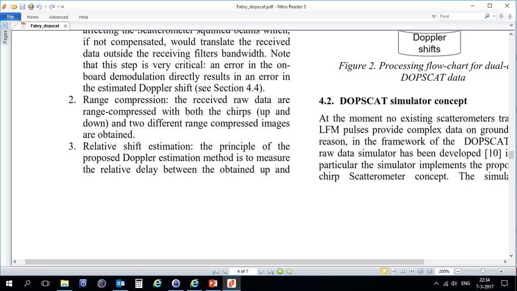
![Scatterer Doppler history, squinted beam case used in the new study [Hz] In the](/docs-images/94/119491739/images/9-0.jpg "new simulations for each scatterer the exact range history is taken into account")
9 Scatterer Doppler history, squinted beam case used in the new study [Hz] In the new simulations for each scatterer the exact range history is taken into account 9
10 Ocean motion determination for a wide footprint wind scatterometer Wind Vector Cell 660 km ~ 0.3 msec transmit waveform 25 km Received signal is the sum of responses from the 2 pulses 334 range cells Unique random phase pattern is same for 2 pulses and allows to avoid range ambiguities (a noise-radar like approach) received signals after pulse compr. time windows for WVC correlation peak from WVC phase pattern peak phase ocean motion 10
 Sufciently large simulation surface, based on pulse lengths 64 / 128 runs of 16 look averages, a total of 1024/2048")
11 Simulation process In the simulation: >7 scatterers per res.cell WVC of 166 resolution cells (25 km) Sufciently large simulation surface, based on pulse lengths 64 / 128 runs of 16 look averages, a total of 1024/2048 independent realisations with scatterers, (long processing times) 45 deg FORE and AFT beams considered 11
12 Pulse pair timing and observation (1) 660 km delay time between transmit waveforms, e.g ms = 21 km 25 km A two pulse waveform will determine phase shift over the selected WVC cell. Area of interest on the time axis selected for the 1st pulse. 2nd pulse signal in this window comes from an area 21 km nearer. 12
13 Pulse pair timing and observation (2) 660 km delay time between transmit waveforms, e.g ms = 21 km 25 km A two-pulse waveform will determine phase shift over the selected WVC cell. Area of interest on the time axis selected for the 2nd pulse. 1st pulse signal in this window comes from an area 21 km further away. 13

14 Pulse-pair coherence and expected radial velocity measurement accuracy Cramér-Rao bound: 1 = 2 ( 2 2 ) (Rodriguez) 2 2 with: = = x50 km WVC looks 8 =0.115 time between pulses 2 =0.coherence 168 squared =113wavenumber =0.61 / 14
15 2 pulse-pair Up/Down chirps ms 15
16 Coherence for up/down chirp 16
17 Measurement accuracy for up/down chirps measuremen t time pulse responses separate (theoretical ) pulse responses combined include regression line phase In ms Precision in m/s for 25 km WVC Precision in m/s for 25 km WVC Precision in m/s for 25 km WVC Precision in m/s for 50 km WVC 0,231 0,2415 0,253 0,2645 0,276 0,2875 0,299 0,3105 0,322 0,3335 0,345 17
18 2 pulse pair down chirps ms 18
19 2 pulse pair up chirps ms 19
20 Accuracy for up- and down chirps, ms, FWD and AFT beam measuremen t time Precision in m/s for 25 km WVC In ms Up chirp FWD beam Up chirp AFT beam Down chirp FWD beam Down chirp AFT beam 0,231 0,2415 0,253 0,2645 0,276 0,2875 0,299 0,3105 0,322 0,3335 0,345 21
21 Accuracy for up chirps, FWD beam, and pulse length measuremen t time Precision in m/s for 25 km WVC In ms 0,115 ms pulse length 0,231 0,2415 0,253 0,2645 0,276 0,2875 0,299 0,3105 0,322 0,3335 0,345 0,3565 0,368 0,134 ms pulse length 0,161 ms pulse length Optimize energy of SCA transmitter Waveform Pulse length 22
22 Accuracy for 3 pulse chirps over 50 km measuremen t time Precision in m/s for 50 km WVC In ms 1st pulse pair Up-up-up 0,339 Dwn-dwn-dwn 0,339 Dwn-dwn-dwn 0,339 Dwn-dwn-dwn 0,345 2nd pulse pair Combined 0,63 0,66 0,65 0,74 0,72 0,66 0,81 0,76 0,69 0,84 0,76 0,65 Note: Simulation area in frst two cases is 95 km long with 4500 refectors. Last two cases have 155 km with 7500 refectors. 23
23 Ideas for follow-on activities The proposed method needs to be investigated and tested with real data. Two goals: 1. Check the phase measurement method and its accuracy. Does it live up to the simulation results? What is furthermore needed in terms of instrument requirements? 2. Investigate the geophysical aspects of the Ocean Current Measurement Some ideas for experimental campaign: Dedicated experiment with the pulse-pair waveform on TerraSAR-X Airborne experiment (Metasensing?) with a scaled confguration (platform speed versus Doppler bandwidth) representative for the SCA confguration (also pulse-pair waveform required) Experiments should be carried out over land (zero current) and over oceans, preferably in areas with some in situ knowledge Investigations of the geophysical aspects could be performed with an instrument on a fxed platform, e.g. in collaboration with other projects (SKIM) Enhance simulation work Investigate instrument consequences (especially pointing). 24
24 Attitude Control? Yaw = Doppler - No cone efect Pitch = Cone F/A asymmetry - Also Doppler Roll = Cone Left/right asymmetry - Also Doppler SCA wind C-DOP -> Doppler expectation Attitude corrections are low orbit phase harmonics Can use 40*2.000 WVCs per orbit Can we estimate 0.2 mrad or 0.01 degrees? Test with ASCAT! 25
25 Conclusions The high-quality wind scatterometer SCA is an excellent starting point for observing ocean motion, as accurate wind input is needed for waves and drifts DopSCA has been investigated and published as a viable concept for SCA, but the efect of the moving platform on the targets was underestimated The SCA development now continues WITHOUT DopSCA specs. SCA-1 and 2 thus likely have no optimal DopSCA capability, but: The digital signal transmitter may allow DopSCA waveforms Pointing knowledge may be proven adequate (TBC on ASCAT) Further simulation studies now provide a feasible concept on SCA with marginal, but potentially useful accuracy, e.g., in hurricane wind conditions or for monthly climatologies DopSCA campaign(s) may be envisaged? 26
26 Back-up slides 27

27 3 pulses timing and observation (1) 1st pulse pair 660 km delay time between transmit waveforms, e.g. 0,115 ms = 17 km 17 km A three pulse waveform will determine phase shift over 3 x the selected WVC cell range, e.g. 3 x 17 km = 51 km range. Area of interest on the time axis selected for the 1st pulse. 2nd and 3rd pulse signals in this window come from areas 17 and 34 km nearer. 28
28 3 pulses timing and observation (2) 1st pulse pair 660 km delay time between transmit waveforms, e.g. 0,115 ms = 17 km 17 km Correlation between signals of the 1st and 2nd window determine phaseshift for the nearest 2 areas (green and red). Area of interest on the time axis selected for the 2nd pulse. 1st and 3rd pulse signals in this window come from areas 17 km nearer and further away. 29
29 3 pulses timing and observation (3) 2nd pulse pair 660 km delay time between transmit waveforms, e.g. 0,115 ms = 17 km 17 km Correlation between signals of the 1st and 2nd window determine phaseshift for the nearest 2 areas (green and red). Area of interest on the time axis selected for the 2nd pulse. 1st and 3rd pulse signals in this window come from areas 17 km nearer and further away. 30
30 3 pulses timing and observation (4) 2nd pulse pair Correlation between 660 km delay time between transmit waveforms, e.g. 0,115 ms = 17 km 17 km signals of the 2nd and 3rd window determines phaseshift for the nearest 2 areas (green and red). Area of interest on the time axis selected for the third pulse. 1st and 2nd pulse signals in this window come from areas 17 and 34 km further away 31
31 Accuracy for 3 pulse chirps measuremen t time Precision in m/s for 50 km WVC In ms 1st pulse pair Up-up-up 0,339 Dwn-dwn-dwn 0,339 Dwn-dwn-dwn 0,339 Dwn-dwn-dwn 0,345 2nd pulse pair Combined 0,63 0,66 0,65 0,74 0,72 0,66 0,81 0,76 0,69 0,84 0,76 0,65 Note: Simulation area in frst two cases is 95 km long with 4500 refectors. Last two cases have 155 km with 7500 refectors. 32
32 Processing & Performance Assessment 1 Modules (slide from Franco MLE (v zfois) ) z z (v ) MLE i 2 GMF,i i 1... N Extensive Monte-Carlo simulations show the capability of DopSCAT in estimating ocean currents with accuracy below 0.2 m/s, at a spatial resolution of 25 km (i.e. spatial sampling of 12.5 km) and a temporal resolution of 24 hrs. High-resolution products have accuracy worse than 1 m/s in ocean current estimates, which is only sufcient to meet the users needs on a monthly time scale by performing temporal averages over stable currents. MLE (vovm f D ) f D,i fˆd,i (vovm ) 2 i 1... N 33
33 34 Observation Principle (slide from Franco Fois) DopSCAT transmits a dual-chirp, that is a combination of an upchirp, and a down-chirp. This waveform allows estimating not only the σº but also the Doppler shift of the ocean. The ambiguity functions of LFM pulses with opposite chirp rates are skewed in opposite direction, meaning that the introduced delay has an opposite sign. Ambiguity function up-chirp Detecte d IRFs Ambiguity function downchirp Crosscorrelatio n τ τ s f D B s (t ) s u (t ) s d (t ) 1 B 2 1 B 2 A exp j 2π f c t t A exp j 2π f c t t rect τ (t ) 2 τ 2 τ 34
34 Level-1 Processing (slide from Franco Fois) Separation Compression Filter [Iwashita et al., 2003] The Doppler shift measured by a space-borne active microwave instrument over the ocean can be expressed as the sum of three main terms: f D _ Total f D _ wind f D _ curr f D _ geo Polarization dependent Polarization independent Level-1 data processing flow for the generation of Normalized Radar Cross section images (left) and for the estimation ocean s Doppler shifts (right). 35

35 2013 paper by Fabry et al with results from extensive study and simulation 36


36 Important notes in this paper 37
37 The disadvantage of the proposed waveform is the non simultaneous measurement of the up and down chirps, which is really necessary. It will be explained and demonstrated later on in this presentation. 38
38 Requested instrument parameters for DopSCAT simultaneous up and down chirp (SCA uses only upchirps) Chirp duration 2 ms instead of 1 ms Chirp bandwidth 1 MHz (unchanged from SCA) Some other points: Improved pointing analysis Doppler calibration over land We want to measure 0,1 1 m/s ocean current; 1 m/s is 35 Hz in Doppler 1 ms measurement time is 1 khz in Doppler resolution PRF for a beam of SCA: 5 Hz; ocean decorrelation time 3 10 ms 39
39 40

40 Range Doppler ambiguity within resolution cells 41
41 Approaches in the basic simulations with up and down chirps The proposed method of Franco Fois with cross-correlation to fnd the ocean current peak is simulated. Instrument parameters are taken from SCA, unless otherwise indicated. The platform (antenna) speed is 6800 m/s. An ocean surface of 17 km wide (azimuth) and 6 km long (range) is considered. It is represented by 600 randomly positioned scatterers of equal strength. The ocean current moves all scatterers in the same way. The analysis is limited to range cells within this area, so range-doppler ambiguities are well represented. In the simulation the transmit chirps can be generated and timed fully independent of each other. On reception the responses of the up and down chirps are kept separated (for simplicity the Separation Compression Filter as described and tested by Franco Fois has not been taken into account). Noise (SNR) has not been taken into account. In the simulations 256 independent realisations of the seasurface and of the received signals are generated. They are processed as 16 runs of 16 looks. So in a run, 16 independent measurements are averaged. The 16 runs are used to produce an average result and a standard deviation. In the graphs the pulselength, the time until the start of the second chirp and the bandwidth of the transmitted chirps are varied. 42
METOP SECOND GENERATION SCATTEROMETER MISSION
 METOP SECOND GENERATION SCATTEROMETER MISSION Franco Fois, Chung-Chi Lin, Hubert Barré, Maurizio Betto, Marc Loiselet and Graeme Mason European Space Agency, Keplerlaan 1, 2200 AG Noordwijk ZH, The Netherlands
Tracking of Moving Targets with MIMO Radar
 Tracking of Moving Targets with MIMO Radar Peter W. Moo, Zhen Ding Radar Sensing & Exploitation Section DRDC Ottawa Research Centre Presentation to 2017 NATO Military Sensing Symposium 31 May 2017 waveform
Ocean SAR altimetry. from SIRAL2 on CryoSat2 to Poseidon-4 on Jason-CS
 Ocean SAR altimetry from SIRAL2 on CryoSat2 to Poseidon-4 on Jason-CS Template reference : 100181670S-EN L. Phalippou, F. Demeestere SAR Altimetry EGM NOC, Southampton, 26 June 2013 History of SAR altimetry
Wide Swath Simultaneous Measurements of Winds and Ocean Surface Currents
 Wide Swath Simultaneous Measurements of Winds and Ocean Surface Currents Ernesto Rodriguez Jet Propulsion Laboratory California Institute of Technology 1 Thanks! The JPL DFS/ERM team for design of the
Radar-Verfahren und -Signalverarbeitung
 Radar-Verfahren und -Signalverarbeitung - Lesson 2: RADAR FUNDAMENTALS I Hon.-Prof. Dr.-Ing. Joachim Ender Head of Fraunhoferinstitut für Hochfrequenzphysik and Radartechnik FHR Neuenahrer Str. 20, 53343
The Delay-Doppler Altimeter
 Briefing for the Coastal Altimetry Workshop The Delay-Doppler Altimeter R. K. Raney Johns Hopkins University Applied Physics Laboratory 05-07 February 2008 1 What is a Delay-Doppler altimeter? Precision
Wave Sensing Radar and Wave Reconstruction
 Applied Physical Sciences Corp. 475 Bridge Street, Suite 100, Groton, CT 06340 (860) 448-3253 www.aphysci.com Wave Sensing Radar and Wave Reconstruction Gordon Farquharson, John Mower, and Bill Plant (APL-UW)
A Bistatic HF Radar for Current Mapping and Robust Ship Tracking
 A Bistatic HF Radar for Current Mapping and Robust Ship Tracking Dennis Trizna Imaging Science Research, Inc. V. 703-801-1417 dennis @ isr-sensing.com www.isr-sensing.com Objective: Develop methods for
China. France Oceanography S A T. Overview of the near-real time wave products of the CFOSAT mission. e l l i t e
 China Overview of the near-real time wave products of the CFOSAT mission C. Tison (1), D. Hauser (2), S. Guibert (1), T. Amiot (1), L. Aouf (3), J.M. Lefèvre (3), B. Chapron (5), N. Corcoral (1), P. Castillan
THE NASA/JPL AIRBORNE SYNTHETIC APERTURE RADAR SYSTEM. Yunling Lou, Yunjin Kim, and Jakob van Zyl
 THE NASA/JPL AIRBORNE SYNTHETIC APERTURE RADAR SYSTEM Yunling Lou, Yunjin Kim, and Jakob van Zyl Jet Propulsion Laboratory California Institute of Technology 4800 Oak Grove Drive, MS 300-243 Pasadena,
Design and Performance Simulation of a Ku-Band Rotating Fan-Beam Scatterometer
 Design and Performance Simulation of a Ku-Band Rotating Fan-Beam Scatterometer Xiaolong DONG, Wenming LIN, Di ZHU, (CSSAR/CAS) PO Box 8701, Beijing, 100190, China Tel: +86-10-62582841, Fax: +86-10-62528127
Rapid scanning with phased array radars issues and potential resolution. Dusan S. Zrnic, V.M.Melnikov, and R.J.Doviak
 Rapid scanning with phased array radars issues and potential resolution Dusan S. Zrnic, V.M.Melnikov, and R.J.Doviak Z field, Amarillo 05/30/2012 r=200 km El = 1.3 o From Kumjian ρ hv field, Amarillo 05/30/2012
Coherent Marine Radar. Measurements of Ocean Wave Spectra and Surface Currents
 Measurements of Ocean Wave Spectra and Surface Currents Dennis Trizna Imaging Science Research, Inc. dennis @ isr-sensing.com Presentation Outline: Introduction: Standard Marine Radar vs. Single Image
Scalable Front-End Digital Signal Processing for a Phased Array Radar Demonstrator. International Radar Symposium 2012 Warsaw, 24 May 2012
 Scalable Front-End Digital Signal Processing for a Phased Array Radar Demonstrator F. Winterstein, G. Sessler, M. Montagna, M. Mendijur, G. Dauron, PM. Besso International Radar Symposium 2012 Warsaw,
Concept Design of Space-Borne Radars for Tsunami Detection
 Concept Design of Space-Borne Radars for Tsunami Detection DLR German Aerospace Agency +Microwaves and Radar Institute *Remote Sensing Institute +Michele Galletti +Gerhard Krieger +Nicolas Marquart +Thomas
Incoherent Scatter Experiment Parameters
 Incoherent Scatter Experiment Parameters At a fundamental level, we must select Waveform type Inter-pulse period (IPP) or pulse repetition frequency (PRF) Our choices will be dictated by the desired measurement
Systems. Advanced Radar. Waveform Design and Diversity for. Fulvio Gini, Antonio De Maio and Lee Patton. Edited by
 Waveform Design and Diversity for Advanced Radar Systems Edited by Fulvio Gini, Antonio De Maio and Lee Patton The Institution of Engineering and Technology Contents Waveform diversity: a way forward to
Lecture 9. Radar Equation. Dr. Aamer Iqbal. Radar Signal Processing Dr. Aamer Iqbal Bhatti
 Lecture 9 Radar Equation Dr. Aamer Iqbal 1 ystem Losses: Losses within the radar system itself are from many sources. everal are described below. L PL =the plumbing loss. L PO =the polarization loss. L
A SAR Conjugate Mirror
 A SAR Conjugate Mirror David Hounam German Aerospace Center, DLR, Microwaves and Radar Institute Oberpfaffenhofen, D-82234 Wessling, Germany Fax: +49 8153 28 1449, E-Mail: David.Hounam@dlr.de Abstract--
MULTI-CHANNEL SAR EXPERIMENTS FROM THE SPACE AND FROM GROUND: POTENTIAL EVOLUTION OF PRESENT GENERATION SPACEBORNE SAR
 3 nd International Workshop on Science and Applications of SAR Polarimetry and Polarimetric Interferometry POLinSAR 2007 January 25, 2007 ESA/ESRIN Frascati, Italy MULTI-CHANNEL SAR EXPERIMENTS FROM THE
Design of an Airborne SLAR Antenna at X-Band
 Design of an Airborne SLAR Antenna at X-Band Markus Limbach German Aerospace Center (DLR) Microwaves and Radar Institute Oberpfaffenhofen WFMN 2007, Markus Limbach, Folie 1 Overview Applications of SLAR
RECOMMENDATION ITU-R S *
 Rec. ITU-R S.1339-1 1 RECOMMENDATION ITU-R S.1339-1* Rec. ITU-R S.1339-1 SHARING BETWEEN SPACEBORNE PASSIVE SENSORS OF THE EARTH EXPLORATION-SATELLITE SERVICE AND INTER-SATELLITE LINKS OF GEOSTATIONARY-SATELLITE
FREQUENCY DECLARATION FOR THE ARGOS-4 SYSTEM. NOAA-WP-40 presents a summary of frequency declarations for the Argos-4 system.
 Prepared by CNES Agenda Item: I/1 Discussed in WG1 FREQUENCY DECLARATION FOR THE ARGOS-4 SYSTEM NOAA-WP-40 presents a summary of frequency declarations for the Argos-4 system. FREQUENCY DECLARATION FOR
Comparison of Two Detection Combination Algorithms for Phased Array Radars
 Comparison of Two Detection Combination Algorithms for Phased Array Radars Zhen Ding and Peter Moo Wide Area Surveillance Radar Group Radar Sensing and Exploitation Section Defence R&D Canada Ottawa, Canada
Nadir Margins in TerraSAR-X Timing Commanding
 CEOS SAR Calibration and Validation Workshop 2008 1 Nadir Margins in TerraSAR-X Timing Commanding S. Wollstadt and J. Mittermayer, Member, IEEE Abstract This paper presents an analysis and discussion of
Know how Pulsed Doppler radar works and how it s able to determine target velocity. Know how the Moving Target Indicator (MTI) determines target
 determines target") Moving Target Indicator 1 Objectives Know how Pulsed Doppler radar works and how it s able to determine target velocity. Know how the Moving Target Indicator (MTI) determines target velocity. Be able to
Moving Target Indicator 1 Objectives Know how Pulsed Doppler radar works and how it s able to determine target velocity. Know how the Moving Target Indicator (MTI) determines target velocity. Be able to
Adaptive SAR Results with the LiMIT Testbed
 Adaptive SAR Results with the LiMIT Testbed Gerald Benitz Adaptive Sensor Array Processing Workshop 7 June 2005 999999-1 Outline LiMIT collection platform SAR sidelobe recovery Electronic Protection (EP)
Prototype Software-based Receiver for Remote Sensing using Reflected GPS Signals. Dinesh Manandhar The University of Tokyo
 Prototype Software-based Receiver for Remote Sensing using Reflected GPS Signals Dinesh Manandhar The University of Tokyo dinesh@qzss.org 1 Contents Background Remote Sensing Capability System Architecture
Ionospheric Propagation Effects on W de Bandwidth Sig Si nals Dennis L. Knepp NorthWest Research NorthW Associates est Research Monterey California
 Ionospheric Propagation Effects on Wide Bandwidth Signals Dennis L. Knepp NorthWest Research Associates 2008 URSI General Assembly Chicago, August 2008 Ionospheric Effects on Propagating Signals Mean effects:
ESA Radar Remote Sensing Course ESA Radar Remote Sensing Course Radar, SAR, InSAR; a first introduction
 Radar, SAR, InSAR; a first introduction Ramon Hanssen Delft University of Technology The Netherlands r.f.hanssen@tudelft.nl Charles University in Prague Contents Radar background and fundamentals Imaging
CYGNSS Wind Retrieval Performance
 International Ocean Vector Wind Science Team Meeting Kailua-Kona, Hawaii USA 6-8 May 2013 CYGNSS Wind Retrieval Performance Chris Ruf (1), Maria-Paola Clarizia (1,2), Andrew O Brien (3), Joel Johnson (3),
Active Cancellation Algorithm for Radar Cross Section Reduction
 International Journal of Computational Engineering Research Vol, 3 Issue, 7 Active Cancellation Algorithm for Radar Cross Section Reduction Isam Abdelnabi Osman, Mustafa Osman Ali Abdelrasoul Jabar Alzebaidi
Shallow Water Fluctuations and Communications
 Shallow Water Fluctuations and Communications H.C. Song Marine Physical Laboratory Scripps Institution of oceanography La Jolla, CA 92093-0238 phone: (858) 534-0954 fax: (858) 534-7641 email: hcsong@mpl.ucsd.edu
Projects LOTHAR and LOTHAR-fatt
 Appendix B Projects LOTHAR and LOTHAR-fatt From 2008 to 2011 the National Laboratory RAdar and Surveillance Systems (RaSS) of the National Inter-universitary Consortium for the Telecommunications (CNIT)
Radar Systems Engineering Lecture 12 Clutter Rejection
 Radar Systems Engineering Lecture 12 Clutter Rejection Part 1 - Basics and Moving Target Indication Dr. Robert M. O Donnell Guest Lecturer Radar Systems Course 1 Block Diagram of Radar System Transmitter
MOBILE RAPID-SCANNING X-BAND POLARIMETRIC (RaXPol) DOPPLER RADAR SYSTEM Andrew L. Pazmany 1 * and Howard B. Bluestein 2
 DOPPLER RADAR SYSTEM Andrew L. Pazmany 1 * and Howard B. Bluestein 2") 16B.2 MOBILE RAPID-SCANNING X-BAND POLARIMETRIC (RaXPol) DOPPLER RADAR SYSTEM Andrew L. Pazmany 1 * and Howard B. Bluestein 2 1 ProSensing Inc., Amherst, Massachusetts 2 University of Oklahoma, Norman,
16B.2 MOBILE RAPID-SCANNING X-BAND POLARIMETRIC (RaXPol) DOPPLER RADAR SYSTEM Andrew L. Pazmany 1 * and Howard B. Bluestein 2 1 ProSensing Inc., Amherst, Massachusetts 2 University of Oklahoma, Norman,
RADIO FREQUENCY AND MODULATION SYSTEMS PART 1: EARTH STATIONS AND SPACECRAFT
 Draft Recommendations for Space Data System Standards RADIO FREQUENCY AND MODULATION SYSTEMS PART 1: EARTH STATIONS AND SPACECRAFT DRAFT RECOMMENDED STANDARD CCSDS 401.0-B-27.1 RED/PINK SHEETS August 2017
Principles of Space- Time Adaptive Processing 3rd Edition. By Richard Klemm. The Institution of Engineering and Technology
 Principles of Space- Time Adaptive Processing 3rd Edition By Richard Klemm The Institution of Engineering and Technology Contents Biography Preface to the first edition Preface to the second edition Preface
DOPPLER RADAR. Doppler Velocities - The Doppler shift. if φ 0 = 0, then φ = 4π. where
 Q: How does the radar get velocity information on the particles? DOPPLER RADAR Doppler Velocities - The Doppler shift Simple Example: Measures a Doppler shift - change in frequency of radiation due to
Target Echo Information Extraction
 Lecture 13 Target Echo Information Extraction 1 The relationships developed earlier between SNR, P d and P fa apply to a single pulse only. As a search radar scans past a target, it will remain in the
POST-EPS WINDSCATTEROMETER CONCEPT TRADE-OFFS AND WIND RETRIEVAL PERFORMANCE ASSESSMENT
 POST-EPS WINDSCATTEROMETER CONCEPT TRADE-OFFS AND WIND RETRIEVAL PERFORMANCE ASSESSMENT C.C. Lin 1, M. Betto 1, M. Belmonte Rivas, A. Stoffelen 3, J. de Kloe 3 1 ESA-ESTEC, Keplerlaan 1, 00 AG Noordwijk,
Introduction to Radar Systems. Clutter Rejection. MTI and Pulse Doppler Processing. MIT Lincoln Laboratory. Radar Course_1.ppt ODonnell
 Introduction to Radar Systems Clutter Rejection MTI and Pulse Doppler Processing Radar Course_1.ppt ODonnell 10-26-01 Disclaimer of Endorsement and Liability The video courseware and accompanying viewgraphs
On the stability of Amazon rainforest backscattering during the ERS-2 Scatterometer mission lifetime
 On the stability of Amazon rainforest backscattering during the ERS- Scatterometer mission lifetime R. Crapolicchio (), P. Lecomte () () Serco S.p.A. c/o ESA-ESRIN Via Galileo Galilei 44 Frascati Italy
2B.6 SALIENT FEATURES OF THE CSU-CHILL RADAR X-BAND CHANNEL UPGRADE
 2B.6 SALIENT FEATURES OF THE CSU-CHILL RADAR X-BAND CHANNEL UPGRADE Francesc Junyent* and V. Chandrasekar, P. Kennedy, S. Rutledge, V. Bringi, J. George, and D. Brunkow Colorado State University, Fort
3. give specific seminars on topics related to assigned drill problems
 HIGH RESOLUTION AND IMAGING RADAR 1. Prerequisites Basic knowledge of radar principles. Good background in Mathematics and Physics. Basic knowledge of MATLAB programming. 2. Course format and dates The
A Bistatic HF Radar for Current Mapping and Robust Ship Tracking
 A Bistatic HF Radar for Current Mapping and Robust Ship Tracking D. B. Trizna Imaging Science Research, Inc. 6103B Virgo Court Burke, VA, 22015 USA Abstract- A bistatic HF radar has been developed for
DESIGN AND DEVELOPMENT OF SIGNAL
 DESIGN AND DEVELOPMENT OF SIGNAL PROCESSING ALGORITHMS FOR GROUND BASED ACTIVE PHASED ARRAY RADAR. Kapil A. Bohara Student : Dept of electronics and communication, R.V. College of engineering Bangalore-59,
Modern radio techniques
 Modern radio techniques for probing the ionosphere Receiver, radar, advanced ionospheric sounder, and related techniques Cesidio Bianchi INGV - Roma Italy Ionospheric properties related to radio waves
GMES Sentinel-1 Transponder Development
 GMES Sentinel-1 Transponder Development Paul Snoeij Evert Attema Björn Rommen Nicolas Floury Malcolm Davidson ESA/ESTEC, European Space Agency, Noordwijk, The Netherlands Outline 1. GMES Sentinel-1 overview
Dynamically Configured Waveform-Agile Sensor Systems
 Dynamically Configured Waveform-Agile Sensor Systems Antonia Papandreou-Suppappola in collaboration with D. Morrell, D. Cochran, S. Sira, A. Chhetri Arizona State University June 27, 2006 Supported by
Waveform Processing of Nadir-Looking Altimetry Data
 Waveform Processing of Nadir-Looking Altimetry Data Mònica Roca and Richard Francis ESA/ESTEC Noordwijk The Netherlands Contents 1. the concept 2. introduction 3. the on-board waveform [how the return
VHF Radar Target Detection in the Presence of Clutter *
 BULGARIAN ACADEMY OF SCIENCES CYBERNETICS AND INFORMATION TECHNOLOGIES Volume 6, No 1 Sofia 2006 VHF Radar Target Detection in the Presence of Clutter * Boriana Vassileva Institute for Parallel Processing,
SPREAD SPECTRUM CHANNEL MEASUREMENT INSTRUMENT
 SPACE SPREAD SPECTRUM CHANNEL MEASUREMENT INSTRUMENT Satellite communications, earth observation, navigation and positioning and control stations indracompany.com SSCMI SPREAD SPECTRUM CHANNEL MEASUREMENT
ECE 476/ECE 501C/CS Wireless Communication Systems Winter Lecture 6: Fading
 ECE 476/ECE 501C/CS 513 - Wireless Communication Systems Winter 2003 Lecture 6: Fading Last lecture: Large scale propagation properties of wireless systems - slowly varying properties that depend primarily
OBSERVATION PERFORMANCE OF A PARIS ALTIMETER IN-ORBIT DEMONSTRATOR
 OBSERVATION PERFORMANCE OF A PARIS ALTIMETER IN-ORBIT DEMONSTRATOR Salvatore D Addio, Manuel Martin-Neira Acknowledgment to: Nicolas Floury, Roberto Pietro Cerdeira TEC-ETP, ETP, Electrical Engineering
UAVSAR in Africa. Quality Assurance and Preliminary Results. Brian Hawkins, UAVSAR Team
 Photo by Sassan Saatchi UAVSAR in Africa Quality Assurance and Preliminary Results Brian Hawkins, UAVSAR Team CEOS SAR Cal/Val Workshop 2016 Copyright 2016 California Institute of Technology. Government
Dual-Beam Interferometry for Ocean Surface Current Vector Mapping
 IEEE TRANSACTIONS ON GEOSCIENCE AND REMOTE SENSING, VOL. 39, NO. 2, FEBRUARY 2001 401 Dual-Beam Interferometry for Ocean Surface Current Vector Mapping Stephen J. Frasier, Member, IEEE, and Adriano J.
RECOMMENDATION ITU-R S.1341*
 Rec. ITU-R S.1341 1 RECOMMENDATION ITU-R S.1341* SHARING BETWEEN FEEDER LINKS FOR THE MOBILE-SATELLITE SERVICE AND THE AERONAUTICAL RADIONAVIGATION SERVICE IN THE SPACE-TO-EARTH DIRECTION IN THE BAND 15.4-15.7
ON WAVEFORM SELECTION IN A TIME VARYING SONAR ENVIRONMENT
 ON WAVEFORM SELECTION IN A TIME VARYING SONAR ENVIRONMENT Ashley I. Larsson 1* and Chris Gillard 1 (1) Maritime Operations Division, Defence Science and Technology Organisation, Edinburgh, Australia Abstract
EVALUATION OF BINARY PHASE CODED PULSE COMPRESSION SCHEMES USING AND TIME-SERIES WEATHER RADAR SIMULATOR
 7.7 1 EVALUATION OF BINARY PHASE CODED PULSE COMPRESSION SCHEMES USING AND TIMESERIES WEATHER RADAR SIMULATOR T. A. Alberts 1,, P. B. Chilson 1, B. L. Cheong 1, R. D. Palmer 1, M. Xue 1,2 1 School of Meteorology,
Polarisation Capabilities and Status of TerraSAR-X
 Polarisation Capabilities and Status of TerraSAR-X Irena Hajnsek, Josef Mittermayer, Stefan Buckreuss, Kostas Papathanassiou German Aerospace Center Microwaves and Radar Institute irena.hajnsek@dlr.de
INTRODUCTION. Basic operating principle Tracking radars Techniques of target detection Examples of monopulse radar systems
 Tracking Radar H.P INTRODUCTION Basic operating principle Tracking radars Techniques of target detection Examples of monopulse radar systems 2 RADAR FUNCTIONS NORMAL RADAR FUNCTIONS 1. Range (from pulse
ASCATTEROMETER is a radar system that measures
 102 IEEE TRANSACTIONS ON GEOSCIENCE AND REMOTE SENSING, VOL. 35, NO. 1, JANUARY 1997 Radar Backscatter Measurement Accuracy for a Spaceborne Pencil-Beam Wind Scatterometer with Transmit Modulation David
Lecture 3 SIGNAL PROCESSING
 Lecture 3 SIGNAL PROCESSING Pulse Width t Pulse Train Spectrum of Pulse Train Spacing between Spectral Lines =PRF -1/t 1/t -PRF/2 PRF/2 Maximum Doppler shift giving unambiguous results should be with in
ASCAT Metop s Advanced Scatterometer
 ASCAT Metop s Advanced Scatterometer R.V. Gelsthorpe Earth Observation Programmes Development Department, ESA Directorate of Application Programmes, ESTEC, Noordwijk, The Netherlands E. Schied Dornier
SuperDARN (Super Dual Auroral Radar Network)
") SuperDARN (Super Dual Auroral Radar Network) What is it? How does it work? Judy Stephenson Sanae HF radar data manager, UKZN Ionospheric radars Incoherent Scatter radars AMISR Arecibo Observatory Sondrestrom
SuperDARN (Super Dual Auroral Radar Network) What is it? How does it work? Judy Stephenson Sanae HF radar data manager, UKZN Ionospheric radars Incoherent Scatter radars AMISR Arecibo Observatory Sondrestrom
Potential interference from spaceborne active sensors into radionavigation-satellite service receivers in the MHz band
 Rec. ITU-R RS.1347 1 RECOMMENDATION ITU-R RS.1347* Rec. ITU-R RS.1347 FEASIBILITY OF SHARING BETWEEN RADIONAVIGATION-SATELLITE SERVICE RECEIVERS AND THE EARTH EXPLORATION-SATELLITE (ACTIVE) AND SPACE RESEARCH
RECOMMENDATION ITU-R S.1340 *,**
 Rec. ITU-R S.1340 1 RECOMMENDATION ITU-R S.1340 *,** Sharing between feeder links the mobile-satellite service and the aeronautical radionavigation service in the Earth-to-space direction in the band 15.4-15.7
Radar Reprinted from "Waves in Motion", McGourty and Rideout, RET 2005
 Radar Reprinted from "Waves in Motion", McGourty and Rideout, RET 2005 What is Radar? RADAR (Radio Detection And Ranging) is a way to detect and study far off targets by transmitting a radio pulse in the
CHAPTER 2 WIRELESS CHANNEL
 CHAPTER 2 WIRELESS CHANNEL 2.1 INTRODUCTION In mobile radio channel there is certain fundamental limitation on the performance of wireless communication system. There are many obstructions between transmitter
Waveform Multiplexing using Chirp Rate Diversity for Chirp-Sequence based MIMO Radar Systems
 Waveform Multiplexing using Chirp Rate Diversity for Chirp-Sequence based MIMO Radar Systems Fabian Roos, Nils Appenrodt, Jürgen Dickmann, and Christian Waldschmidt c 218 IEEE. Personal use of this material
RECOMMENDATION ITU-R SA.1624 *
 Rec. ITU-R SA.1624 1 RECOMMENDATION ITU-R SA.1624 * Sharing between the Earth exploration-satellite (passive) and airborne altimeters in the aeronautical radionavigation service in the band 4 200-4 400
SCIRoCCo Scatterometry Glossary
 Scatterometry Prepared by: The Team: Change register Version/Rev. Date Reason for Change Changes 1.0 08/05/2014 First Release. Preliminary version 1.1 20/02/2015 4 th bi-monthly Report Review Contributions
DIGITAL BEAM-FORMING ANTENNA OPTIMIZATION FOR REFLECTOR BASED SPACE DEBRIS RADAR SYSTEM
 DIGITAL BEAM-FORMING ANTENNA OPTIMIZATION FOR REFLECTOR BASED SPACE DEBRIS RADAR SYSTEM A. Patyuchenko, M. Younis, G. Krieger German Aerospace Center (DLR), Microwaves and Radar Institute, Muenchner Strasse
Multi-Path Fading Channel
 Instructor: Prof. Dr. Noor M. Khan Department of Electronic Engineering, Muhammad Ali Jinnah University, Islamabad Campus, Islamabad, PAKISTAN Ph: +9 (51) 111-878787, Ext. 19 (Office), 186 (Lab) Fax: +9
Lecture 6 SIGNAL PROCESSING. Radar Signal Processing Dr. Aamer Iqbal Bhatti. Dr. Aamer Iqbal Bhatti
 Lecture 6 SIGNAL PROCESSING Signal Reception Receiver Bandwidth Pulse Shape Power Relation Beam Width Pulse Repetition Frequency Antenna Gain Radar Cross Section of Target. Signal-to-noise ratio Receiver
Pulse Compression. Since each part of the pulse has unique frequency, the returns can be completely separated.
 Pulse Compression Pulse compression is a generic term that is used to describe a waveshaping process that is produced as a propagating waveform is modified by the electrical network properties of the transmission
A new Sensor for the detection of low-flying small targets and small boats in a cluttered environment
 UNCLASSIFIED /UNLIMITED Mr. Joachim Flacke and Mr. Ryszard Bil EADS Defence & Security Defence Electronics Naval Radar Systems (OPES25) Woerthstr 85 89077 Ulm Germany joachim.flacke@eads.com / ryszard.bil@eads.com
Space-Time Adaptive Processing: Fundamentals
 Wolfram Bürger Research Institute for igh-frequency Physics and Radar Techniques (FR) Research Establishment for Applied Science (FGAN) Neuenahrer Str. 2, D-53343 Wachtberg GERMANY buerger@fgan.de ABSTRACT
A STUDY OF DOPPLER BEAM SWINGING USING AN IMAGING RADAR
 .9O A STUDY OF DOPPLER BEAM SWINGING USING AN IMAGING RADAR B. L. Cheong,, T.-Y. Yu, R. D. Palmer, G.-F. Yang, M. W. Hoffman, S. J. Frasier and F. J. López-Dekker School of Meteorology, University of Oklahoma,
Theoretical Simulations of GNSS Reflections from Bare and Vegetated Soils
 Theoretical Simulations of GNSS Reflections from Bare and Vegetated Soils R. Giusto 1, L. Guerriero, S. Paloscia 3, N. Pierdicca 1, A. Egido 4, N. Floury 5 1 DIET - Sapienza Univ. of Rome, Rome DISP -
Ka-Band Systems and Processing Approaches for Simultaneous High-Resolution Wide-Swath SAR Imaging and Ground Moving Target Indication
 Ka-Band Systems and Processing Approaches for Simultaneous High-Resolution Wide-Swath SAR Imaging and Ground Moving Target Indication Advanced RF Sensors and Remote Sensing Instruments 2014 Ka-band Earth
Microwave Transponders and Links ACES MWL and beyond
 Workshop on Optical Clocks Düsseldorf, 08 / 09 Mar 2007 Microwave Transponders and Links ACES MWL and beyond W. SCHÄFER 1, M.P. HESS 2, 1 TimeTech GmbH, Stuttgart, Germany Wolfgang.Schaefer@timetech.de
SYSTEM ARCHITECTURE OF RADAR NETWORK FOR MONITORING OF HAZARDOUD WEATHER
 SYSTEM ARCHITECTURE OF RADAR NETWORK FOR MONITORING OF HAZARDOUD WEATHER 2008. 11. 21 HOON LEE Gwangju Institute of Science and Technology &. CONTENTS 1. Backgrounds 2. Pulse Compression 3. Radar Network
ECE 476/ECE 501C/CS Wireless Communication Systems Winter Lecture 6: Fading
 ECE 476/ECE 501C/CS 513 - Wireless Communication Systems Winter 2004 Lecture 6: Fading Last lecture: Large scale propagation properties of wireless systems - slowly varying properties that depend primarily
ECE 476/ECE 501C/CS Wireless Communication Systems Winter Lecture 6: Fading
 ECE 476/ECE 501C/CS 513 - Wireless Communication Systems Winter 2005 Lecture 6: Fading Last lecture: Large scale propagation properties of wireless systems - slowly varying properties that depend primarily
Frequency Synchronization in Global Satellite Communications Systems
 IEEE TRANSACTIONS ON COMMUNICATIONS, VOL. 51, NO. 3, MARCH 2003 359 Frequency Synchronization in Global Satellite Communications Systems Qingchong Liu, Member, IEEE Abstract A frequency synchronization
Rec. ITU-R P RECOMMENDATION ITU-R P *
 Rec. ITU-R P.682-1 1 RECOMMENDATION ITU-R P.682-1 * PROPAGATION DATA REQUIRED FOR THE DESIGN OF EARTH-SPACE AERONAUTICAL MOBILE TELECOMMUNICATION SYSTEMS (Question ITU-R 207/3) Rec. 682-1 (1990-1992) The
Frequency-Modulated Continuous-Wave Radar (FM-CW Radar)
") Frequency-Modulated Continuous-Wave Radar (FM-CW Radar) FM-CW radar (Frequency-Modulated Continuous Wave radar = FMCW radar) is a special type of radar sensor which radiates continuous transmission power
Frequency-Modulated Continuous-Wave Radar (FM-CW Radar) FM-CW radar (Frequency-Modulated Continuous Wave radar = FMCW radar) is a special type of radar sensor which radiates continuous transmission power
Channel. Muhammad Ali Jinnah University, Islamabad Campus, Pakistan. Multi-Path Fading. Dr. Noor M Khan EE, MAJU
 Instructor: Prof. Dr. Noor M. Khan Department of Electronic Engineering, Muhammad Ali Jinnah University, Islamabad Campus, Islamabad, PAKISTAN Ph: +9 (51) 111-878787, Ext. 19 (Office), 186 (Lab) Fax: +9
Aquarius/SAC-D and Soil Moisture
 Aquarius/SAC-D and Soil Moisture T. J. Jackson P. O Neill February 24, 2011 Aquarius/SAC-D and Soil Moisture + L-band dual polarization + Combined active and passive Coarse spatial resolution (~100 km)
GNSS Ocean Reflected Signals
 GNSS Ocean Reflected Signals Per Høeg DTU Space Technical University of Denmark Content Experimental setup Instrument Measurements and observations Spectral characteristics, analysis and retrieval method
Non-coherent pulse compression - concept and waveforms Nadav Levanon and Uri Peer Tel Aviv University
 Non-coherent pulse compression - concept and waveforms Nadav Levanon and Uri Peer Tel Aviv University nadav@eng.tau.ac.il Abstract - Non-coherent pulse compression (NCPC) was suggested recently []. It
TanDEM-X: Mission Status & Scientific Contribution
 TanDEM-X: Mission Status & Scientific Contribution Irena Hajnsek 1/2, Gerhard Krieger 1, Kostas Papathanassiou 1, Stefan Baumgartner 1, Marc Rodriguez-Cassola 1, Pau Prats 1, Maria Sanjuan Ferrer 1, Florian
Digital Sounder: HF Diagnostics Module:Ionosonde Dual Channel ( ) Eight Channel ( )
 Eight Channel ( )") CENTER FOR REMOTE SE NSING, INC. Digital Sounder: HF Diagnostics Module:Ionosonde Dual Channel (001-2000) Eight Channel (004-2006) 2010 Center for Remote Sensing, Inc. All specifications subject to change
CENTER FOR REMOTE SE NSING, INC. Digital Sounder: HF Diagnostics Module:Ionosonde Dual Channel (001-2000) Eight Channel (004-2006) 2010 Center for Remote Sensing, Inc. All specifications subject to change
Diversity. Presented by ENG.: Ahmed Hamza Supervisor: Dr. Mohab Mangoud
 Diversity Presented by ENG.: Ahmed Hamza Supervisor: Dr. Mohab Mangoud Outline Introduction. What is diversity? Why? Types of diversity Space diversity. Polarization diversity. Frequency diversity. Time
Radar astronomy and radioastronomy using the over-the-horizon radar NOSTRADAMUS. ONERA, Département Electromagnétisme et Radar
 Radar astronomy and radioastronomy using the over-the-horizon radar NOSTRADAMUS J-F. Degurse 1,2, J-Ph. Molinié 1, V. Rannou 1,S. Marcos 2 1 ONERA, Département Electromagnétisme et Radar 2 L2S Supéléc,
RF and Microwave Test and Design Roadshow 5 Locations across Australia and New Zealand
 RF and Microwave Test and Design Roadshow 5 Locations across Australia and New Zealand ni.com Design and test of RADAR systems Agenda Radar Overview Tools Overview VSS LabVIEW PXI Design and Simulation
Remote sensing of the oceans Active sensing
 Remote sensing of the oceans Active sensing Gravity Sea level Ocean tides Low frequency motion Scatterometry SAR http://daac.gsfc.nasa.gov/campaign_docs/ocdst/what_is_ocean_color.html Shape of the earth
4-10 Development of the CRL Okinawa Bistatic Polarimetric Radar
 4-10 Development of the CRL Okinawa Bistatic Polarimetric Radar NAKAGAWA Katsuhiro, HANADO Hiroshi, SATOH Shinsuke, and IGUCHI Toshio Communications Research Laboratory (CRL) has developed a new C-band