带输出关断的 20V,14A 全集成同步升压转换器
|
|
|
- Evan Cannon
- 5 years ago
- Views:
Transcription
1 特点 输入电压范围 V PIN :2.7V-20V 输出电压范围 V OUT :4.5V-20V 可编程峰值电流 :14A 带输出关断的 20V,14A 全集成同步升压转换器 高转换效率 : 95% (V PIN = 7.2V, V OUT =16V, I OUT =3A) 94% (V PIN = 12V, V OUT =18V, I OUT =4A) 90% (V PIN = 3.3, V OUT =9V, I OUT =3A) 轻载条件下两种调制方式 : 脉频调制 (PFM) 和 强制脉宽调试 (PWM) 集成输出关断的栅极驱动 低关断功耗, 关断电流 1uA 可调节的开关频率 :200k-1.4M 可编程软启动 输出过压 (22V) 逐周期过流 热关断等保护 DFN20,4.5mm*3.5mm 无铅超薄封装 应用 无线音箱 快充移动电源 便携式音箱 电子烟 USB TYPE-C 电源传输 拉杆音箱 平板电脑, 笔记本电脑 典型应用图 POS 机终端 概述 同步升压转换器 是一款高功率 全集成升压转换器, 带有负载关断功能的栅极驱动, 集成 16mΩ 功率开关管和 16mΩ 同步整流管, 为便携式系统提供高效的小尺寸解决方案 具有 2.7V 至 20V 宽输入电压范围, 可为采用单节或两节锂电池, 或 12V 铅酸电池的应用提供支持 该器件具备 14A 开关电流能力, 并且能够提供高达 20V 的输出电压 采用自适应恒定关断时间峰值电流控制拓扑结构来调节输出电压 在中等到重负载条件下, 工作在 PWM 模式 在轻负载条件下, 该器件可通过 MODE 引脚选择下列两种工作模式之一 一种是可提高效率的 PFM 模式 ; 另一种是可避免因开关频率较低而引发应用问题的强制 PWM 模式 PWM 模式下, 的开关频率可通过外部电阻调节, 支持 200kHz 至 1.4MHz 的范围 还支持可编程的软启动, 以及可调节的开关峰值电流限制 另外, 集成了输出关断功能的栅极驱动, 在 SD 状态, 可完全断开输入电源 此外, 该器件还提供有 22V 输出过压保护 逐周期过流保护和热关断保护 2.2uF C VCC R ILIM VPIN: V VPIN 470uF10uF 10uF 1uF L VIN VIN: V OFF 10uF ON R FREQ C BOOT 0.1uF 0.1uF EN FSW SW BOOT VIN C SS VCC SS 47nF AGND PGND DIS ILIM COMP FB VOUT MODE 1uF C P C C R C R DN R UP 10uF10uF 10uF 10uF R GATE C GATE VOUT: V 470uF VOUT Optional TEL: panxia168@126.com
2 20V,14A Fully-Integrated with Load Disconnect Control FEATURES Input voltage range VPIN: 2.7V to 20V Output voltage range VOUT: 4.5V to 20V Programmable switch peak current limit: up to 14A High Efficiency 95% (VPIN = 7.2V, VOUT=16V, IOUT =3A) 94% (VPIN = 12V, VOUT=18V, IOUT =4A) 90% (VPIN = 3.3, VOUT=9V, IOUT =3A) 2 modulation mode available: PFM or PWM mode at light load Integrated gate driver for load disconnect and output short protection 1.0μA current consumption during shutdown Adjustable switching frequency: 200k to 1.4MHz Programmable soft start Output overvoltage protection (at 22V), cycle-bycycle overcurrent protection, thermal shutdown protection Pb-free Packages,DFN20, 4.5mm*3.5mm APPLICATIONS Wireless/ Speakers Portable Speakers Quick Charge Power Bank E-Cigarette Power Interface (USB Type-C, Thunderbolt) POS Terminal Tablet PC/Note Book DESCRIPTION The is a high-power density, fully integrated synchronous boost converter with a 16mΩ power switch and a 16mΩ rectifier switch to provide a high efficiency and small size solution in portable systems. The has wide input voltage range from 2.7 V to 20 V to support applications with single cell, two cell Lithium batteries and 12V lead-acid batteries. The device has 14A switch current capability and can provide an output voltage up to 20V. The uses adaptive constant off-time peak current control topology to regulate the output voltage. In moderate to heavy load condition, it works in the PWM mode. In light load condition, the device has two operation modes selected by the MODE pin. One is PFM mode to improve the efficiency and another one is the forced PWM mode to avoid application problems caused by low switching frequency. The switching frequency in the PWM mode is adjustable ranging from 200kHz to 1.4MHz by an external resistor. could isolate the output from input side when shut down by a gate drive output disconnecting external FET, so that the load current consumption could be limited. The also implements a programmable softstart function and an adjustable switching peak current limit function. In addition, the device provides 22V output overvoltage protection, cycleby-cycle overcurrent protection, and thermal shutdown protection. TYPICAL APPLICATION 2.2uF C VCC R ILIM VPIN: V VPIN 470uF10uF 10uF 1uF L OFF ON R FREQ C BOOT EN FSW SW BOOT VCC AGND PGND ILIM COMP FB VOUT 1uF C P C C R C R DN R UP 10uF10uF 10uF 10uF VOUT: V 470uF VOUT VIN: V VIN 10uF 0.1uF 0.1uF VIN C SS SS 47nF DIS MODE R GATE C GATE Optional
3 TERMINAL CONFIGURATION TERMINAL FUNCTION Terminal No. NAME I/O *1 Description 1 VCC O Output of the internal regulator. A ceramic capacitor of 2.2uF is required between this pin and ground. 2 EN I Enable logic input. Logic high level enables the device. Logic low level disables the device and turns it into shutdown mode. 3 FSW I The switching frequency is programmed by a resister between this pin and the SW pin. 4/5/6/7 SW PWR The switching node pin of the converter. 8 BOOT O Power supply for high-side MOSTFET gate driver. A ceramic capacitor of 0.1μF must be connected between this pin and the SW pin. 9 VIN I IC power supply input. 10 SS O Soft-start programming pin. An external capacitor connected to ground sets the ramp rate of the internal error amplifier s reference voltage during soft-start 11 DIS O A gate drive output for the external disconnect FET. Connect the DISDRV pin to the gate of the external FET. Leave it floating if not using the load disconnect function. 12 NC - No connection inside the device. Connect these two pins to ground plane on the PCB for good thermal dissipation. 13 MODE I Operation mode selection pin for the device in light load condition. When this pin is connected to ground, the device works in PWM mode. When this pin is left floating, the device works in PFM mode. 14/15/16 VOUT PWR Boost converter output. 17 FB I Voltage feedback. 18 COMP O Output of the internal error amplifier, the loop compensation network should be connected between this pin and the AGND pin. 19 ILIM I Adjustable switch peak current limit. An external resister should be connected between this pin and the AGND pin. 20 AGND - Signal ground of the IC. 0 PGND PWR Power ground of the IC. *1 I: input O: output PWR: power
4 ORDERING INFORMATION H T Part Number Package Type Marking DFN20 *2:UVWXYZ is production track code. UVWXYZ *2 Operating Temperature Range -40 ~85 MOQ/Shipping Package Reel
5 ELECTRICAL CHARACTERISTIC Absolute Maximum Ratings *3 Voltage range PARAMETER Symbol MIN MAX UNIT BOOT -0.3 SW+7 SW, FSW, VOUT, DIS, VPIN VIN / EN, VCC, SS, COMP, MODE ILIM, FB Operating temperature range TA Operating junction temperature range TJ Storage temperature range TSTG *3: Stresses beyond those listed under absolute maximum ratings may cause permanent damage to the device. These are stress ratings only, and functional operation of the device at these or any other conditions beyond those indicated under recommended operating conditions is not implied. Exposure to absolute maximum rated conditions for extended periods may affect device reliability. Recommended Operating Conditions PARAMETER Symbol CONDITION MIN TYP MAX UNIT Input power voltage range VPIN V IC power supply voltage range VIN V Output voltage range VOUT V Inductance, effective value L μh Input capacitance, effective value CI μf Output capacitance, effective value CO μf Operating temperature Ta Operating junction temperature TJ V
6 Electrical Characteristics *4 Condition: Ta = 25ºC, VPIN = 2.7V-20V, VOUT=4.5-20V, unless otherwise specified. PARAMETER Symbol CONDITION MIN TYP MAX UNIT Power Supply Input power voltage range IC power supply voltage range Under-voltage lockout (UVLO) threshold VPIN V VIN V VIN_UVLO VIN rising 2.7 V VIN falling 2.5 V VIN UVLO hysteresis VIN_HYS 200 mv VCC UVLO threshold VCC_UVLO 2.1 V Operating quiescent current from VPIN + VIN Shutdown current into VPIN + VIN IQ ISD VIN =VPIN = 3.3V, VOUT = 7.5V 600 VIN =VPIN = 7.2V, VOUT = 12V 390 VIN =VPIN = 12V, VOUT = 18V 460 IC disabled, VIN =VPIN = 3.6 V 1 ua IC disabled, VIN =VPIN = 7.4 V 4 VCC regulation VCC 5.2 V EN and Mode Input EN high threshold voltage EN low threshold voltage EN internal pull-down resistance MODE high threshold voltage MODE low threshold voltage MODE internal pull-up resistance OUTPUT VENH 1.5 V VENL 0.4 V REN 800 kω VMODEH 4 V VMODEL 1.5 V RMODE 800 kω Output voltage range VOUT Freq = 500 khz V Output overvoltage protection VOVP V Reference voltage at the FB pin VREF V Soft-start charging current ISS 5 ua ERROR AMPLIFIER COMP pin sink current ISINK VFB = VREF +200 mv, VCOMP = 1.5 V 20 ua COMP pin source current ISOURCE VFB = VREF 200 mv, VCOMP = 1.5 V 20 ua High clamp voltage at the COMP pin VCC_LPH VFB = 1 V, RILIM = 100 kω 2.3 V Low clamp voltage at the COMP pin VCC_LPL VFB = 1.5 V, RILIM = 100 kω, 1.4 V Error amplifier transconductance GEA VCOMP = 1.5 V 190 ua/v POWER SWITCH on- MOSFET resistance CURRENT LIMIT Peak switch current limit Reference voltage at the ILIM pin SWITCHING FREQUENCY RDS(on) ILIM High-side MOSFET 16 mω Low-side MOSFET 16 mω RILIM = 100 kω, RILIM = 82 kω, VILIM V ua A
7 Switching frequency ƒsw RFREQ = 220 kω, VPIN = 3.6V, VOUT = 12V 600 khz Minimum on-time ton_min RFREQ = 220 kω, VPIN = 3.6V, VOUT = 12V ns GATE DRIVER FOR LOAD DISCONNECT Driver current for the IGD_SINK 55 ua external FET THERMAL SHUTDOWN Thermal shutdown threshold Thermal shutdown hysteresis TSD 150 TSD_HYS 20 *4:Depending on parts and pattern layout, characteristics may be changed. Voltage Setting Reference for Input Power Referred Max Input Current (RMS Value) Input Voltage Output Voltage Referred Max Output Current (RMS Value) Output Power Efficiency Pull-up resistor from FB Pull-down resistor from FB PPIN (W) IPIN(A) VPIN(V) VOUT(V) IOUT(A) POUT (W) η(%) RUP(Ω) RDN(Ω) % 510k 100k % 510k 75k % 510k 56k % 510k 56k % 510k 43k % 510k 36k % 510k 36k % 510k 33k
8 TYPICAL OPERATING CHARACTERISTICS Condition: L = 1.5uH, RILIM = 82k,RFREQ = 200k, Output Capacitor = 1uF//10uF//10uF//220uF, PFM mode, otherwise specified.
9
10 APPLICATION INFORMATION 1. Typical Application 2.2u F 1 20 C3 47 0uF V PIN 10 uf10 uf1u F V IN L1 C 18 R7 EN R1 20 0k 10 uf 1u F C2 0.1u F EN FS W SW SW SW SW B OO ST V IN PGND SS H T71 78 R4 R3 10 0k 19 ILIM 18 C OMP 17 FB MODE C4 1u F 10 uf10 uf R k C nf R6 R5 VOUT Q1 A ON uf 47 0uF 0 10 AGND DIS ILIM C OMP FB V OU T V OU T V OU T MO DE NC 11 VCC H T nf D IS DR V Do make sure that the voltage peak of pin VIN should be lower than 12V. If the input power voltage is higher than 12V (VPIN > 12V), use a 3.3V or 5V logic power supply to connect VIN or use a lager resistor connecting between VPIN and VIN. 2. Feature Description 2.1. Functional Modes (Mode pin) Operation The synchronous boost converter operates at a quasi-constant frequency pulse width modulation (PWM) in moderate to heavy load condition. Based on the VPIN to VOUT ratio, a circuit predicts the required off-time of the switching cycle. At the beginning of each switching cycle, the low-side N-MOSFET switch is turned on, and the inductor current ramps up to a peak current that is determined by the output of the internal error amplifier. After the peak current is reached, the current comparator trips, and it turns off the low-side N-MOSFET switch and the inductor current goes through the body diode of the high-side N- MOSFET in a dead-time duration. After the dead-time duration, the high-side N-MOSFET switch is turned on. Because the output voltage is higher than the input voltage, the inductor current decreases. The highside switch is not turned off until the fixed off-time is reached. After a short dead-time duration, the low-side switch turns on again and the switching cycle is repeated. In light load condition, the implements two operation modes, PFM mode and forced PWM mode, to meet different application requirements. The operation mode is set by the status of the MODE pin. When the MODE pin is connected to ground, the device works in the forced PWM mode. When the MODE pin is left floating, the device works in the PFM mode, which is the recommended mode. PWM Mode In the forced PWM mode, the keeps the switching frequency unchanged in light load condition. When the load current decreases, the output of the internal error amplifier decreases as well to keep the inductor peak current down, delivering less power from input to output. When the output current further reduces, the current through the inductor will decrease to zero during the off-time. The high-side N- MOSFET is not turned off even if the current through the MOSFET is zero. Thus, the inductor current changes its direction after it runs to zero. The power flow is from output side to input side. The efficiency will be low in this mode. But with the fixed switching frequency, there is no audible noise and other problems which might be caused by low switching frequency in light load condition. PFM Mode
11 The improves the efficiency at light load with the PFM mode. When the converter operates in light load condition, the output of the internal error amplifier decreases to make the inductor peak current down, delivering less power to the load. When the output current further reduces, the current through the inductor will decrease to zero during the off-time. Once the current through the high side N-MOSFET is zero, the high-side MOSFET is turned off until the beginning of the next switching cycle. When the output of the error amplifier continuously goes down and reaches a threshold with respect to the peak current of ILIM / 12, the output of the error amplifier is clamped at this value and does not decrease any more. If the load current is smaller than what the delivers, the output voltage increases above the nominal setting output voltage. The extends its off time of the switching period to deliver less energy to the output and regulate the output voltage to 0.7% higher than the nominal setting voltage. With the PFM operation mode, the keeps the efficiency above 80% even when the load current decreases to 1 ma. In addition, the output voltage ripple is much smaller at light load due to low peak current Enable and Startup (EN and SS pin) The has an adjustable soft start function to prevent high inrush current during start-up. To minimize the inrush current during start-up, an external capacitor, connected to the SS pin and charged with a constant current, is used to slowly ramp up the internal positive input of the error amplifier. The larger the capacitance at the SS pin, the slower the ramp of the output voltage and the longer the soft-start time. A 47-nF capacitor is usually sufficient for most applications. When the EN pin is pulled into logic low (below 0.4V), the goes into the shutdown mode and stops switching. Only when EN pin is pulled into logic high (above 1.5V), the works Adjustable Switching Frequency (FSW pin) This device features a wide adjustable switching frequency ranging from 200 khz to 1.4MHz. The switching frequency is set by a resistor (RFREQ) connected between the FSW pin and the SW pin of the. RFREQ must always be connected from the FSW pin to SW pin for proper operation. RFREQ can be calculated by: where R FREQ = 4 ( 1 f SW t DELAY V OUT V PIN ) C FREQ RFREQ is the resistance connected between the FSW pin and the SW pin. CFREQ = 23pF. ƒsw is the desired switching frequency. tdelay = 89 ns. VPIN is the input voltage. VOUT is the output voltage. NOTE: A resistor value of k is recommended for RFREQ to get a fsw of around kHz Load Disconnect Gate Driver (DIS pin) The provides a DIS pin to drive the external FET at the output side, which completely disconnects the output from the input end during shutdown or output short happens. During the device s start-up phase, the disconnect FET is controlled by the gate driver voltage of the external disconnect FET, there is an internal 55μA (typical) sink current. The load disconnect FET connection is shown as Figure 1. Do make sure that COUT2 should be no larger than 10 x COUT1 to avoid the inrush current when turning on the disconnect FET.
12 The FET parameter should be considered as follows: Figure 1 Load Disconnect FET Connection The drain-to-source voltage rating VDS should be higher than the output max. voltage VOUT. The drain-to-source RMS current rating IDS(RMS) should be higher than the maximum output current. The driver voltage and turn on / off timing can be set via the resistor RGATE and capacitor CGATE connecting between with the DIS pin and the source of the external FET. 150K and 22nF can be used in most cases. To set the CGATE, the following equation can be used: where C GATE C GS_PFET = T ON_PFET I DIS_PFET V TH_PFET CGS_PFET is the total gate capacitance of connected between gate and source external FET. (including the self-gate-source capacitance of the FET). The maximum capacitance CGS_PFET should be < 100nF. TON_PFET is the turn on time of external FET. The max TON_PFET should not exceed 3ms IDIS_PFET is the discharge current inside of, it is 55μA typically. VTH_PFET is the gate threshold of external FET. To set the RGATE, the following equation can be used: R GATE = I DIS_PFET While DIS is not used, it can be connected to GND so that a more integral GND plane can be achieved to decrease the loop of output peak current Adjustable Peak Current Limit (ILIM pin) To avoid an accidental large peak current, an internal cycle-by-cycle current limit is adopted. The low-side switch is turned off immediately as soon as the switch current touches the limit. The peak switch current limit can be set by a resistor (RILIM) at the ILIM pin to ground. The relationship between the current limit and the resistance is as follows: 2.6. Output Voltage Setting (FB pin) V GATE I LIM = R ILIM
13 The output voltage is set by an external resistor divider (RUP, RDN in the Typical Application Circuit). To get the output voltage VOUT, the Value of RUP and RDN can be calculated as: Where VREF = 1.204V. V OUT = V REF (1 + R UP R DN ) Some typical output voltages can be set as the following parameters. VOUT(V) RUP(Ω) RDN(Ω) k 75k k 56k k 43k 2.7. Inductor Selection (SW pin) k 36k Because the selection of the inductor affects the power supply s steady state operation, transient behavior, loop stability, and boost converter efficiency, the inductor is the most important component in switching power regulator design. Three most important specifications to the performance of the inductor are the inductor value, DC resistance, and saturation current. To be simplified, the inductor value can be set as 2.2uH which can be used in most cases. The rated current, especially the saturation current should be larger than the peak current during the whole operation. The peak current can be calculated as follows. I Lpeak = I DC + I PP 2 I DC = V OUT I OUT V IN η 1 I PP = 1 L ( + 1 ) f V OUT V IN V SW IN Boost converter efficiency is affected significantly by the inductor s DC resistance (DCR), equivalent series resistance (ESR) at the switching frequency, and the core loss. An inductor with lower DCR and ESR would increase the efficiency significantly. The inductor should be placed as close as possible to the SW pin. For a lower EMI radiation, connecting a resistor and a capacitor in series to the ground would be helpful. 1ohm resistor and 10nF capacitor would be recommended in most cases Input Capacitor Selection (VIN, VPIN, VCC pin) For good input voltage filtering and small voltage ripple (less than 100mV is required), we recommend low- ESR capacitors of 1uF//10uF//10uF//470uF ( // represents paralleled) be placed as close as possible to the inductor. The VIN pin is the power supply for the, a 1uF paralleled with 10uF ceramic capacitor should be placed as close as possible to the VIN pin. Notice that the maximum voltage of VIN should be lower than 12V, so if VIN is supplied from VPIN, a resistor of 10R is required between input power supply VPIN and VIN pin so that the power supply of would be more stable, and if VPIN is larger than 12V, the value of the resistor should be higher to get a lower voltage of VIN. An extensive power supply such as the logic power supply connecting to VIN would be another choice. Be aware of that the current consumption of VIN is lower than 10mA. The VCC pin is the output of internal LDO. A ceramic capacitor of 2.2uF is required at the VCC pin to get a stable operation of LDO.
14 2.9. Output Capacitor Selection (VOUT pin) To be simplified, we recommend low-esr capacitors of 1uF//10uF//10uF//470uF ( // represents paralleled) be placed as close as possible to VOUT pin for small output voltage ripple. Capacitors can lose most of their capacitance at rated voltage. Therefore, leave margin on the voltage rating to ensure adequate effective capacitance. In detail, for the require output voltage ripple, use the following equations to calculate the minimum required effective capacitance COUT Where V ripple_dis = (V OUT V PINMIN ) I OUT V OUT f SW C OUT V ripple_esr = I Lpeak R C_ESR Vripple_dis is output voltage ripple caused by charging and discharging of the output capacitor. Vripple_ESR is output voltage ripple caused by ESR of the output capacitor. VPIN_MIN is the minimum input voltage of boost converter.. VOUT is the output voltage.. IOUT is the output current. ILpeak is the peak current of the inductor. ƒsw is the converter switching frequency. RC_ESR is the ESR of the output capacitors Loop Stability (COMP pin) The requires external compensation, which allows the loop response to be optimized for each application. The COMP pin is the output of the internal error amplifier. An external compensation network comprised of resister RC, ceramic capacitors CC and CP is connected to the COMP pin. To be simplified, RC is 56kΩ, CC is 3.3nF, and CP can be floating. But notice that this setting can only be adopted in most cases. In detail, the compensation network parameters can be calculated as follows. (1) Set the cross over frequency, ƒc The first step is to set the loop crossover frequency, ƒc. The higher crossover frequency, the faster the loop response is. It is generally accepted that the loop gain cross over no higher than the lower of either 1/10 of the switching frequency, ƒsw, or 1/5 of the RHPZ frequency, ƒrhpz. It s proper to use a fixed parameter of 10kHz for ƒc. (2) Set the compensation resistor, RC. f RHPZ = R O (1 D) 2 2π L (3) Set the compensation zero capacitor, CC (4) Set the compensation pole capacitor, CP R C = 2π V OUT R sense f C C O (1 D) V REF G EA C C = R O C O 2 R C C P = R ESR C O R C
15 If the CP is less than 10pF, it can be left open. RO is the output load resistance. D is the switching duty cycle. 1 - D = VPIN / VOUT Rsense is the equivalent internal current sense resistor, which is Ω. CO is output capacitor. VREF is the reference voltage at the FB pin, which is 1.204V. GEA is the amplifier s transconductance, which is 190uA/V. RESR is the equivalent series resistance of the output capacitor Selecting the Bootstrap Capacitor (BOOT pin) The bootstrap capacitor (CBST) between the BOOT and SW pin supplies the gate current to charge the high-side FET device gate during each cycle s turn-on and supplies charge for the bootstrap capacitor. The recommended value of the bootstrap capacitor is 0.1μF to 1μF. CBST should be a good quality, low ESR, ceramic capacitor located at the pins of the device to minimize potentially damaging voltage transients caused by trace inductance. A value of 0.1μF can be used in most cases Protection Function Under-voltage Lockout (UVLO) The UVLO circuit prevents the device from malfunctioning at low input voltage and the battery from excessive discharge. The has both VIN UVLO function and VCC UVLO function. It disables the device from switching when the falling voltage at the VIN pin trips the UVLO threshold VIN_UVLO, which is typically 2.4V. The device starts operating when the rising voltage at the VIN pin is 200mV above the VIN_UVLO. It also disables the device when the falling voltage at the VCC pin trips the UVLO threshold VCC_UVLO, which is typically 2.1V. Over-voltage Protection If the output voltage at the VOUT pin is detected above 22 V (typical value), the stops switching immediately until the voltage at the VOUT pin drops the hysteresis value lower than the output overvoltage protection threshold. This function prevents overvoltage on the output and secures the circuits connected to the output from excessive overvoltage. Thermal Shutdown A thermal shutdown is implemented to prevent damages due to excessive heat and power dissipation. Typically, the thermal shutdown happens at a junction temperature of 150 C. When the thermal shutdown is triggered, the device stops switching until the junction temperature falls below typically 130 C, then the device starts switching again.

16 3. Application Notes 3.1. Radiated EMI Reduction (1) Minimize High di/dt Path Loop Area EMI Starts off from high di/dt loops. The high di/dt critical path locates as the red circle showed in the following figure. The output capacitor should be placed as close to the VOUT pin as possible resulting in minimum area of the high di/dt loop. The DIS pin (when not used) and NC pin can be connected to PGND ground plane which is good for thermal dissipation, can reduce the impedance of the return path and make the placement of the output capacitors easier. (2) PCB Trace and Ground Plane Figure 2 Critical Path Layout High trace inductance leads to poor radiation EMI. The inductance of a PCB trance is a function of its length and width. So, increase the trace width and decrease the trace length will significantly decrease the radiation EMI. Meanwhile, good designed ground planes will help decrease the radiation EMI too: Placing a solid ground plane with minimum distance to the critical trace; Wider and bigger ground plane result in smaller signal trace inductance; Thinner insulation thickness between the ground plane and the signal traces also results in smaller inductance; (3) RC Snubber Adding an RC snubber across the SW pin and the power ground can help reduce the radiation EMI levels. The RC snubber should be placed as close as possible to the switching node and the power ground. SW R S CS Figure 3 Placement of RC Snubber The aim of the snubber resistor RS is to add sufficient damping to the parasitic resonant circuit. The value of RS depends on the desired damping factor and the parasitic inductor IP and parasitic capacitor CP of the circuit: R S = 1 ξ L P C P
17 Where ξ is the damping factor, normally can range from 0.5 to 1. The value of LP and CP can be measured by: Measure the original ringing frequency fring; Add some small capacitance from switch node to ground. Keep increasing capacitance until the ringing frequency is 50% of the original ringing frequency fring, and the capacitance is CS, CP = 1/(3CS); L P = 1 C P (2π f RING ) 2 To be simplified, a resistor of 1ohm (RS) and a capacitor of 2.2nF (CS) can be used. However, notice that larger CS results in higher power loss. (4) Radiation from Cables A longer input or output cables result in poor radiation EMI. So, make the length of input cable and output cable very close to the real application. (5) Ferrite Bead Ferrite Bead is used in series with the power line. Before using a ferrite bead, you need to consider about the specifications of the bead as follows: The frequency characteristics Make sure that the resistive impedance of the bead is much higher than the reactive impedance in the noise frequency range. The rated current Make sure that the rated current of the bead should be at least 30% higher than the expected maximum current. The DC resistance The DC resistance of the ferrite bead should be as low as possible Layout Guidelines As for all switching power supplies, especially those running at high switching frequency and high currents, layout is an important design step. If layout is not carefully done, the regulator could suffer from instability and noise problems. To maximize efficiency, switch rise and fall times are very fast. To prevent radiation of high frequency noise (for example, EMI), proper layout of the high-frequency switching path is essential. Minimize the length and area of all traces connected to the SW pin, and always use a ground plane under the switching regulator to minimize interplane coupling. The input capacitor needs to be close to inductor L, the VIN pin and GND pin in order to reduce the input supply ripple. The output capacitor needs to be close to VOUT pin and GND pin in order to reduce the output supply ripple. The layout should also be done with well consideration of the thermal as this is a high-power density device. A thermal pad that improves the thermal capabilities of the package should be soldered to the large ground plate, using thermal vias underneath the thermal pad.

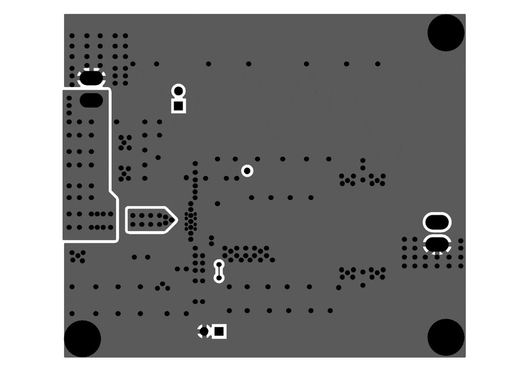
18 3.3. Layout Examples
19 PACKAGE OUTLINE
idesyn id8802 2A, 23V, Synchronous Step-Down DC/DC
 2A, 23V, Synchronous Step-Down DC/DC General Description Applications The id8802 is a 340kHz fixed frequency PWM synchronous step-down regulator. The id8802 is operated from 4.5V to 23V, the generated
DESCRIPTION FEATURES APPLICATIONS TYPICAL APPLICATION. 500KHz, 18V, 2A Synchronous Step-Down Converter
 DESCRIPTION The is a fully integrated, high-efficiency 2A synchronous rectified step-down converter. The operates at high efficiency over a wide output current load range. This device offers two operation
TFT-LCD DC/DC Converter with Integrated Backlight LED Driver
 TFT-LCD DC/DC Converter with Integrated Backlight LED Driver Description The is a step-up current mode PWM DC/DC converter (Ch-1) built in an internal 1.6A, 0.25Ω power N-channel MOSFET and integrated
AT V,3A Synchronous Buck Converter
 FEATURES DESCRIPTION Wide 8V to 40V Operating Input Range Integrated 140mΩ Power MOSFET Switches Output Adjustable from 1V to 25V Up to 93% Efficiency Internal Soft-Start Stable with Low ESR Ceramic Output
WD3122EC. Descriptions. Features. Applications. Order information. High Efficiency, 28 LEDS White LED Driver. Product specification
 High Efficiency, 28 LEDS White LED Driver Descriptions The is a constant current, high efficiency LED driver. Internal MOSFET can drive up to 10 white LEDs in series and 3S9P LEDs with minimum 1.1A current
FEATURES DESCRIPTION APPLICATIONS PACKAGE REFERENCE
 DESCRIPTION The is a monolithic synchronous buck regulator. The device integrates 100mΩ MOSFETS that provide 2A continuous load current over a wide operating input voltage of 4.75V to 25V. Current mode
A7221A DC-DC CONVERTER/BUCK (STEP-DOWN) 600KHz, 16V, 2A SYNCHRONOUS STEP-DOWN CONVERTER
 600KHz, 16V, 2A SYNCHRONOUS STEP-DOWN CONVERTER") DESCRIPTION The is a fully integrated, high efficiency 2A synchronous rectified step-down converter. The operates at high efficiency over a wide output current load range. This device offers two operation
DESCRIPTION The is a fully integrated, high efficiency 2A synchronous rectified step-down converter. The operates at high efficiency over a wide output current load range. This device offers two operation
LSP5502 2A Synchronous Step Down DC/DC Converter
 FEATURES 2A Output Current Wide 4.5V to 27V Operating Input Range Integrated 20mΩ Power MOSFET Switches Output Adjustable from 0.925V to 24V Up to 96% Efficiency Programmable Soft-Start Stable with Low
WD3119 WD3119. High Efficiency, 40V Step-Up White LED Driver. Descriptions. Features. Applications. Order information 3119 FCYW 3119 YYWW
 High Efficiency, 40V Step-Up White LED Driver Http//:www.sh-willsemi.com Descriptions The is a constant current, high efficiency LED driver. Internal MOSFET can drive up to 10 white LEDs in series and
EUP3410/ A,16V,380KHz Step-Down Converter DESCRIPTION FEATURES APPLICATIONS. Typical Application Circuit
 2A,16V,380KHz Step-Down Converter DESCRIPTION The is a current mode, step-down switching regulator capable of driving 2A continuous load with excellent line and load regulation. The can operate with an
1MHz, 3A Synchronous Step-Down Switching Voltage Regulator
 FEATURES Guaranteed 3A Output Current Efficiency up to 94% Efficiency up to 80% at Light Load (10mA) Operate from 2.8V to 5.5V Supply Adjustable Output from 0.8V to VIN*0.9 Internal Soft-Start Short-Circuit
EUP3452A. 2A,30V,300KHz Step-Down Converter DESCRIPTION FEATURES APPLICATIONS. Typical Application Circuit
 2A,30V,300KHz Step-Down Converter DESCRIPTION The is current mode, step-down switching regulator capable of driving 2A continuous load with excellent line and load regulation. The can operate with an input
Techcode. 1.6A 32V Synchronous Rectified Step-Down Converte TD1529. General Description. Features. Applications. Package Types DATASHEET
 General Description Features The TD1529 is a monolithic synchronous buck regulator. The device integrates two 130mΩ MOSFETs, and provides 1.6A of continuous load current over a wide input voltage of 4.75V
4.5V to 32V Input High Current LED Driver IC For Buck or Buck-Boost Topology CN5816. Features: SHDN COMP OVP CSP CSN
 4.5V to 32V Input High Current LED Driver IC For Buck or Buck-Boost Topology CN5816 General Description: The CN5816 is a current mode fixed-frequency PWM controller for high current LED applications. The
MP1482 2A, 18V Synchronous Rectified Step-Down Converter
 The Future of Analog IC Technology MY MP48 A, 8 Synchronous Rectified Step-Down Converter DESCRIPTION The MP48 is a monolithic synchronous buck regulator. The device integrates two 30mΩ MOSFETs, and provides
1.5MHz, 3A Synchronous Step-Down Regulator
 1.5MHz, 3A Synchronous Step-Down Regulator FP6165 General Description The FP6165 is a high efficiency current mode synchronous buck PWM DC-DC regulator. The internal generated 0.6V precision feedback reference
HM2259D. 2A, 4.5V-20V Input,1MHz Synchronous Step-Down Converter. General Description. Features. Applications. Package. Typical Application Circuit
 HM2259D 2A, 4.5V-20V Input,1MHz Synchronous Step-Down Converter General Description Features HM2259D is a fully integrated, high efficiency 2A synchronous rectified step-down converter. The HM2259D operates
600KHz, 16V/2A Synchronous Step-down Converter
 600KHz, 16V/2A Synchronous Step-down Converter General Description The contains an independent 600KHz constant frequency, current mode, PWM step-down converters. The converter integrates a main switch
1.5MHz, 1.5A Step-Down Converter
 1.5MHz, 1.5A Step-Down Converter General Description The is a 1.5MHz constant frequency current mode PWM step-down converter. It is ideal for portable equipment which requires very high current up to 1.5A
EUP A,40V,200KHz Step-Down Converter
 3A,40V,200KHz Step-Down Converter DESCRIPTION The is current mode, step-down switching regulator capable of driving 3A continuous load with excellent line and load regulation. The operates with an input
DT V 1A Output 400KHz Boost DC-DC Converter FEATURES GENERAL DESCRIPTION APPLICATIONS ORDER INFORMATION
 GENERAL DESCRIPTION The DT9111 is a 5V in 12V 1A Out step-up DC/DC converter The DT9111 incorporates a 30V 6A N-channel MOSFET with low 60mΩ RDSON. The externally adjustable peak inductor current limit
High Efficiency 8A Synchronous Boost Convertor
 High Efficiency 8A Synchronous Boost Convertor General Description The is a synchronous current mode boost DC-DC converter. Its PWM circuitry with built-in 8A current power MOSFET makes this converter
10A Current Mode Non-Synchronous PWM Boost Converter
 10A Current Mode Non-Synchronous PWM Boost Converter General Description The is a current mode boost DC-DC converter. It is PWM circuitry with built-in 15mΩ power MOSFET make this regulator highly power
SGM6132 3A, 28.5V, 1.4MHz Step-Down Converter
 GENERAL DESCRIPTION The SGM6132 is a current-mode step-down regulator with an internal power MOSFET. This device achieves 3A continuous output current over a wide input supply range from 4.5V to 28.5V
RT V DC-DC Boost Converter. Features. General Description. Applications. Ordering Information. Marking Information
 RT8580 36V DC-DC Boost Converter General Description The RT8580 is a high performance, low noise, DC-DC Boost Converter with an integrated 0.5A, 1Ω internal switch. The RT8580's input voltage ranges from
DIO6305 High-Efficiency 1.2MHz, 1.1A Synchronous Step-Up Converter
 High-Efficiency 1.2MHz, 1.1A Synchronous Step-Up Converter Rev 1.2 Features High-Efficiency Synchronous-Mode 2.7-5.25V input voltage range Device Quiescent Current: 30µA (TYP) Less than 1µA Shutdown Current
MA V Synchronous Buck Converter GENERAL DESCRIPTION FEATURES APPLICATION CIRCUIT
 38V Synchronous Buck Converter GENERAL DESCRIPTION The MA5601 is a monolithic synchronous buck regulator. The device integrates two internal power MOSFETs, and provides 2.5A of continuous load current
Low-Noise 4.5A Step-Up Current Mode PWM Converter
 Low-Noise 4.5A Step-Up Current Mode PWM Converter FP6298 General Description The FP6298 is a current mode boost DC-DC converter. It is PWM circuitry with built-in 0.08Ω power MOSFET make this regulator
2A, 23V, 380KHz Step-Down Converter
 2A, 23V, 380KHz Step-Down Converter General Description The is a buck regulator with a built-in internal power MOSFET. It achieves 2A continuous output current over a wide input supply range with excellent
1MHz, 3A Synchronous Step-Down Switching Voltage Regulator
 FEATURES Guaranteed 3A Output Current Efficiency up to 95% Operate from 2.8V to 5.5V Supply Adjustable Output from 0.8V to VIN*0.86 Internal Soft-Start Short-Circuit and Thermal -Overload Protection 1MHz
HF A 27V Synchronous Buck Converter General Description. Features. Applications. Package: TBD
 General Description The is a monolithic synchronous buck regulator. The device integrates 80 mω MOSFETS that provide 4A continuous load current over a wide operating input voltage of 4.5V to 27V. Current
ACE726C. 500KHz, 18V, 2A Synchronous Step-Down Converter. Description. Features. Application
 Description The is a fully integrated, high-efficiency 2A synchronous rectified step-down converter. The operates at high efficiency over a wide output current load range. This device offers two operation
Non-Synchronous PWM Boost Controller
 Non-Synchronous PWM Boost Controller FP5209 General Description The FP5209 is a boost topology switching regulator for wide operating voltage applications. It provides built-in gate driver pin, EXT pin,
UM1660. Low Power DC/DC Boost Converter UM1660S SOT23-5 UM1660DA DFN AAG PHO. General Description
 General Description Low Power DC/DC Boost Converter S SOT23-5 DA DFN6 2.0 2.0 The is a PFM controlled step-up DC-DC converter with a switching frequency up to 1MHz. The device is ideal to generate output
1.5MHz, 2A Synchronous Step-Down Regulator
 1.5MHz, 2A Synchronous Step-Down Regulator General Description The is a high efficiency current mode synchronous buck PWM DC-DC regulator. The internal generated 0.6V precision feedback reference voltage
FP6276B 500kHz 6A High Efficiency Synchronous PWM Boost Converter
 500kHz 6A High Efficiency Synchronous PWM Boost Converter General Description The is a current mode boost DC-DC converter with PWM/PSM control. Its PWM circuitry with built-in 40mΩ high side switch and
MP2313 High Efficiency 1A, 24V, 2MHz Synchronous Step Down Converter
 The Future of Analog IC Technology MP2313 High Efficiency 1A, 24V, 2MHz Synchronous Step Down Converter DESCRIPTION The MP2313 is a high frequency synchronous rectified step-down switch mode converter
Ecranic EC V 1A 1.5MHz Synchronous Buck Converter FEATURES GENERAL DESCRIPTION APPLICATIONS ORDER INFORMATION
 GENERAL DESCRIPTION The is a high-efficiency, DC-to-DC step-down switching regulators, capable of delivering up to 1.2A of output current. The operates from an input voltage range of 2.5V to 5.5V and provides
23V, 3A, 340KHz Synchronous Step-Down DC/DC Converter
 23V, 3A, 340KHz Synchronous Step-Down DC/DC Converter Description The is a synchronous step-down DC/DC converter that provides wide 4.5V to 23V input voltage range and 3A continuous load current capability.
Application Notes: AN_SY8208A
 Application Notes: High Efficiency Fast Response 8A Continuous, 16A Peak, 28V Input Synchronous Step Down Regulator General Description The SY8208A develops a high efficiency synchronous step-down DC-DC
FP A Current Mode Non-Synchronous PWM Boost Converter
 10A Current Mode Non-Synchronous PWM Boost Converter General Description The is a current mode boost DC-DC converter. It is PWM circuitry with built-in 15mΩ power MOSFET make this regulator highly power
DIO6970 High-Efficiency 2A, 24V Input Synchronous Step Down Converter
 DIO6970 High-Efficiency 2A, 24V Input Synchronous Step Down Converter Rev 0.2 Features Low R DS(ON) for internal switches (top/bottom) 130mΩ/80mΩ, 2.0A 4.5-24V input voltage range High-Efficiency Synchronous-Mode
2A, 20V Synchronous Step-Down Converter DESCRIPTION FEATURES APPLICATIOS TYPICAL APPLICATION. Parameters Subject to Change Without Notice
 2A, 20 Synchronous Step-Down Converter P Parameters Subject to Change Without Notice DESCRIPTION The is a current mode monolithic buck voltage converter. Operating with an input range of 4.7-20, the delivers
340KHz, 36V/2.5A Step-down Converter With Soft-Start
 340KHz, 36V/2.5A Step-down Converter With Soft-Start General Description The contains an independent 340KHz constant frequency, current mode, PWM step-down converters. The converter integrates a main switch
A7221 DC-DC CONVERTER/ BUCK (STEP-DOWN) HIGH EFFICIENCY FAST RESPONSE, 2A, 16V INPUT SYNCHRONOUS STEP-DOWN CONVERTER
 HIGH EFFICIENCY FAST RESPONSE, 2A, 16V INPUT SYNCHRONOUS STEP-DOWN CONVERTER") DESCRIPTION develops high efficiency synchronous step-down DC-DC converter capable of delivering 2A load current. operates over a wide input voltage range from 6V to 16V and integrates main switch and
DESCRIPTION develops high efficiency synchronous step-down DC-DC converter capable of delivering 2A load current. operates over a wide input voltage range from 6V to 16V and integrates main switch and
DT V 400KHz Boost DC-DC Controller FEATURES GENERAL DESCRIPTION APPLICATIONS ORDER INFORMATION
 GENERAL DESCRIPTION The DT9150 is a 5V step-up DC/DC controller designed capable of deliver over 50V Output with proper external N-MOSFET devices. The DT9150 can work with most Power N-MOSFET devices,
ACP A Synchronous Buck Converter GENERAL DESCRIPTION FEATURES APPLICATION CIRCUIT PIN DESCRIPTION. Feb
 GENERAL DESCRIPTION The ACP2808 is a high efficiency synchronous, PWM step-down DC/DC converter capable of delivering up to 1.2A of output current. The device operates from an input voltage range of 2.6V
AT MHz 2A Step Up DC-DC Converter
 FEATURES DESCRIPTION up to 93% Efficiency Integrated 80mΩ Power MOSFET 2.3V to 24V Input Voltage 1.2MHz Fixed Switching Frequency Internal 4A Switch Current Limit Adjustable Output Voltage up to 28V Internal
SGM6232 2A, 38V, 1.4MHz Step-Down Converter
 GENERAL DESCRIPTION The is a current-mode step-down regulator with an internal power MOSFET. This device achieves 2A continuous output current over a wide input supply range from 4.5V to 38V with excellent
AT V Synchronous Buck Converter
 38V Synchronous Buck Converter FEATURES DESCRIPTION Wide 8V to 38V Operating Input Range Integrated two 140mΩ Power MOSFET Switches Feedback Voltage : 220mV Internal Soft-Start / VFB Over Voltage Protection
ACE732E. 6V/3.5A, Fast Response, Step-Down Converter
 Description ACE732E belongs to a new breed of high frequency synchronous Step-Down converter that combines the advantages of voltage mode control and Constant-On-Time control. Its adaptive Constant-On-Time
38V Synchronous Buck Converter With CC/CV
 38V Synchronous Buck Converter With CC/CV GENERAL DESCRIPTION MA5602 is a wide input voltage, high efficiency Active CC step-down DC/DC converter that operates in either CV (Constant Output Voltage) mode
3A, 23V, 380KHz Step-Down Converter
 3A, 23V, 380KHz Step-Down Converter General Description The is a buck regulator with a built in internal power MOSFET. It achieves 3A continuous output current over a wide input supply range with excellent
A7406A DC-DC CONVERTER BUCK (STEP-DOWN) 40V, 600mA ASYNCHRONOUS
 40V, 600mA ASYNCHRONOUS") DESCRIPTION The is a high frequency (1.8MHz) step-down switching regulator with integrated internal high-side high voltage power MOSFET. It provides single 0.6A(or less) highly efficient output with current
DESCRIPTION The is a high frequency (1.8MHz) step-down switching regulator with integrated internal high-side high voltage power MOSFET. It provides single 0.6A(or less) highly efficient output with current
DIO6010 High-Efficiency 1.5MHz, 1A Continuous, 1.5A Peak Output Synchronous Step Down Converter
 DIO6010 High-Efficiency 1.5MHz, 1A Continuous, 1.5A Peak Output Synchronous Step Down Converter Rev 1.2 Features Low R DS(ON) for internal switches (top/bottom) 230mΩ/170mΩ, 1.0A 2.5-5.5V input voltage
PS7516. Description. Features. Applications. Pin Assignments. Functional Pin Description
 Description The PS756 is a high efficiency, fixed frequency 550KHz, current mode PWM boost DC/DC converter which could operate battery such as input voltage down to.9.. The converter output voltage can
MP2305 2A, 23V Synchronous Rectified Step-Down Converter
 The Future of Analog IC Technology MP305 A, 3 Synchronous Rectified Step-Down Converter DESCRIPTION The MP305 is a monolithic synchronous buck regulator. The device integrates 30mΩ MOSFETS that provide
AIC2858 F. 3A 23V Synchronous Step-Down Converter
 3A 23V Synchronous Step-Down Converter FEATURES 3A Continuous Output Current Programmable Soft Start 00mΩ Internal Power MOSFET Switches Stable with Low ESR Output Ceramic Capacitors Up to 95% Efficiency
Analog Technologies. ATI2202 Step-Down DC/DC Converter ATI2202. Fixed Frequency: 340 khz
 Step-Down DC/DC Converter Fixed Frequency: 340 khz APPLICATIONS LED Drive Low Noise Voltage Source/ Current Source Distributed Power Systems Networking Systems FPGA, DSP, ASIC Power Supplies Notebook Computers
High Efficiency 1MHz, Step up Regulator
 General Description Features The is the high power and high efficiency boost converter with an integrated 30V FET ideal for LCD panel backlighting applications. 30V output voltage allows for 8 high power
3-Channel Constant Current LED Driver UCS1903
 3-Channel Constant Current LED Driver UCS1903 (Products descriptions) The product UCS1903 is the three-channel LED drive control circuit, internal integration MCU digital interface, data latches, LED high
Techcode TD8213. High Efficiency 1.2MHz Step Up Regulator. Features. General Description. Applications. Pin Assignments DATASHEET
 General Description Features The is the high power and high efficiency boost converter with an integrated 30V FET ideal for LCD panel backlighting applications. 30V output voltage allows for 8 high-power
Features MIC2193BM. Si9803 ( 2) 6.3V ( 2) VDD OUTP COMP OUTN. Si9804 ( 2) Adjustable Output Synchronous Buck Converter
 6.3V ( 2) VDD OUTP COMP OUTN. Si9804 ( 2) Adjustable Output Synchronous Buck Converter") MIC2193 4kHz SO-8 Synchronous Buck Control IC General Description s MIC2193 is a high efficiency, PWM synchronous buck control IC housed in the SO-8 package. Its 2.9V to 14V input voltage range allows
MIC2193 4kHz SO-8 Synchronous Buck Control IC General Description s MIC2193 is a high efficiency, PWM synchronous buck control IC housed in the SO-8 package. Its 2.9V to 14V input voltage range allows
HM V~5V Input 12W Output Step-up DC/DC Converter GENERAL DESCRIPTION FEATURES APPLICATIONS
 3.3V~5V Input 12W Output Step-up DC/DC Converter GENERAL DESCRIPTION The HM9226 is a high frequency, high efficiency DC to DC converter with an integrated 6A, 40mÙ power switch capable of providing an
Pin Assignment Pin No. Pin Name Descripition 1 BS High-Side Gate Drive Boost Input. BS supplies the drive for the highside N-Channel MOSFET switch. Co
 Description The is a monolithic synchronous buck regulator. The device integrates MOSFETS that provide 2A continuous load current over a wide Operating input voltage of 4.7V to 18V. Current mode control
DIO6605B 5V Output, High-Efficiency 1.2MHz, Synchronous Step-Up Converter
 5V Output, High-Efficiency 1.2MHz, Synchronous Step-Up Converter Rev 0.2 Features High-Efficiency Synchronous-Mode 2.7-4.5V input voltage range Device Quiescent Current: 30µA(TYP) Less than 1µA Shutdown
HM V 3A 500KHz Synchronous Step-Down Regulator
 Features Wide 4V to 18V Operating Input Range 3A Continuous Output Current 500KHz Switching Frequency Short Protection with Hiccup-Mode Built-in Over Current Limit Built-in Over Voltage Protection Internal
RT8086B. 3.5A, 1.2MHz, Synchronous Step-Down Converter. General Description. Features. Ordering Information RT8086B. Applications. Marking Information
 RT8086B 3.5A, 1.2MHz, Synchronous Step-Down Converter General Description The RT8086B is a high efficiency, synchronous step-down DC/DC converter. The available input voltage range is from 2.8V to 5.5V
HM1410 FEATURES APPLICATIONS PACKAGE REFERENCE HM1410
 DESCRIPTION The is a monolithic step-down switch mode converter with a built in internal power MOSFET. It achieves 2A continuous output current over a wide input supply range with excellent load and line
CEP8101A Rev 1.0, Apr, 2014
 Wide-Input Sensorless CC/CV Step-Down DC/DC Converter FEATURES 42V Input Voltage Surge 40V Steady State Operation Up to 2.1A output current Output Voltage 2.5V to 10V Resistor Programmable Current Limit
EUP A,30V,500KHz Step-Down Converter DESCRIPTION FEATURES APPLICATIONS. Typical Application Circuit
 5A,30V,500KHz Step-Down Converter DESCRIPTION The is current mode, step-down switching regulator capable of driving 5A continuous load with excellent line and load regulation. The operates with an input
UNISONIC TECHNOLOGIES CO., LTD UCC36351 Preliminary CMOS IC
 UNISONIC TECHNOLOGIES CO., LTD UCC36351 Preliminary CMOS IC 36V SYNCHRONOUS BUCK CONVERTER WITH CC/CV DESCRIPTION UTC UCC36351 is a wide input voltage, high efficiency Active CC step-down DC/DC converter
SGM6130 3A, 28.5V, 385kHz Step-Down Converter
 GENERAL DESCRIPTION The SGM6130 is a current-mode step-down regulator with an internal power MOSFET. This device achieves 3A continuous output current over a wide input supply range from 4.5 to 28.5 with
LSP A 23V Synchronous Buck Converter. General Description. Features. Applications. LSP5526 Rev of /8/1.
 General Description The LSP5526 is a monolithic synchronous buck regulator. The device integrates 95mΩ MOSFETS that provide 2A continuous load current over a wide operating input voltage of 4.5V to 23V.
MP2307 3A, 23V, 340KHz Synchronous Rectified Step-Down Converter
 The Future of Analog IC Technology TM TM MP307 3A, 3, 340KHz Synchronous Rectified Step-Down Converter DESCRIPTION The MP307 is a monolithic synchronous buck regulator. The device integrates 00mΩ MOSFETS
CEP8113A Rev 2.0, Apr, 2014
 Wide-Input Sensorless CC/CV Step-Down DC/DC Converter FEATURES 42V Input Voltage Surge 40V Steady State Operation Up to 3.5A output current Output Voltage 2.5V to 10V Resistor Programmable Current Limit
1.0MHz,24V/2.0A High Performance, Boost Converter
 1.0MHz,24V/2.0A High Performance, Boost Converter General Description The LP6320C is a 1MHz PWM boost switching regulator designed for constant-voltage boost applications. The can drive a string of up
NX7101 2A, High Voltage Synchronous Buck Regulator
 is a 340kHz fixed frequency, current mode, PWM synchronous buck (step-down) DC- DC converter, capable of driving a 2A load with high efficiency, excellent line and load regulation. The device integrates
Techcode. High Efficiency 1MHz, 2A Step Up Regulator TD8208. General Description. Features. Applications. Package Types DATASHEET
 General Description Features TD8208 is a high efficiency, current mode control Boost DC to DC regulator with an integrated 120mΩ RDS(ON) N channel MOSFET. The fixed 1MHz switching frequency and internal
RT9270 High Performance, Low Noise Boost Converter General Description Features 90% Efficiency IN Operating Range: 2.3V to 5.5V 1.9A, 0.
 High Performance, Low Noise Boost Converter General Description The is a high performance, low noise, fixed frequency step up DC-DC Converter. The converters input voltage ranging.3v to 5.5V into output
Wide Input Voltage Boost Controller
 Wide Input Voltage Boost Controller FEATURES Fixed Frequency 1200kHz Voltage-Mode PWM Operation Requires Tiny Inductors and Capacitors Adjustable Output Voltage up to 38V Up to 85% Efficiency Internal
ELM614BA 2A, 18V, 500kHz, synchronous step down DC/DC converter
 General description Maximum absolute ratings ELM614BA is a highfrequency, synchronous, rectified, stepdown, switchmode converter with internal power MOSFETs. It offers a very compact solution to achieve
MIC2298. Features. General Description. Applications. Typical Application. 3.5A Minimum, 1MHz Boost High Brightness White LED Driver
 3.5A Minimum, 1MHz Boost High Brightness White LED Driver General Description The is a high power boost-switching regulator that is optimized for constant-current control. The is capable of driving up
UNISONIC TECHNOLOGIES CO., LTD
 UNISONIC TECHNOLOGIES CO., LTD 38V 5A SYNCHRONOUS BUCK CONVERTER DESCRIPTION The UTC UD38501 is a monolithic synchronous buck regulator. The device integrates internal high side and external low side power
UNISONIC TECHNOLOGIES CO., LTD UD38252
 UNISONIC TECHNOLOGIES CO., LTD UD38252 38V SYNCHRONOUS BUCK CONVERTER WITH CC/CV DESCRIPTION UTC UD38252 is a wide input voltage, high efficiency Active CC step-down DC/DC converter that operates in either
MP2324 High Efficiency 2A, 24V, 500kHz Synchronous Step-Down Converter
 MP2324 High Efficiency 2A, 24V, 500kHz Synchronous Step-Down Converter DESCRIPTION The MP2324 is a high frequency synchronous rectified step-down switch mode converter with built in internal power MOSFETs.
EUP V/12V Synchronous Buck PWM Controller DESCRIPTION FEATURES APPLICATIONS. Typical Application Circuit. 1
 5V/12V Synchronous Buck PWM Controller DESCRIPTION The is a high efficiency, fixed 300kHz frequency, voltage mode, synchronous PWM controller. The device drives two low cost N-channel MOSFETs and is designed
PRODUCTION DATA SHEET
 is a 340kHz fixed frequency, current mode, PWM synchronous buck (step-down) DC- DC converter, capable of driving a 3A load with high efficiency, excellent line and load regulation. The device integrates
Features MIC2194BM VIN EN/ UVLO CS OUTP VDD FB. 2k COMP GND. Adjustable Output Buck Converter MIC2194BM UVLO
 MIC2194 400kHz SO-8 Buck Control IC General Description s MIC2194 is a high efficiency PWM buck control IC housed in the SO-8 package. Its 2.9V to 14V input voltage range allows it to efficiently step
FP kHz 7A High Efficiency Synchronous PWM Boost Converter
 500kHz 7A High Efficiency Synchronous PWM Boost Converter General Description The FP6277 is a current mode boost DC-DC converter with PWM/PSM control. Its PWM circuitry with built-in 30mΩ high side switch
MP1484 3A, 18V, 340KHz Synchronous Rectified Step-Down Converter
 The Future of Analog IC Technology MP484 3A, 8, 340KHz Synchronous Rectified Step-Down Converter DESCRIPTION The MP484 is a monolithic synchronous buck regulator. The device integrates top and bottom 85mΩ
MP1570 3A, 23V Synchronous Rectified Step-Down Converter
 Monolithic Power Systems MP570 3A, 23 Synchronous Rectified Step-Down Converter FEATURES DESCRIPTION The MP570 is a monolithic synchronous buck regulator. The device integrates 00mΩ MOSFETS which provide
MP A, 15V, 800KHz Synchronous Buck Converter
 The Future of Analog IC Technology TM TM MP0.5A, 5, 00KHz Synchronous Buck Converter DESCRIPTION The MP0 is a.5a, 00KHz synchronous buck converter designed for low voltage applications requiring high efficiency.
3A, 36V, Step-Down Converter
 3A, 36, Step-Down Converter FP6150 General Description The FP6150 is a buck regulator with a built in internal power MOSFET. It achieves 3A continuous output current over a wide input supply range with
MP1472 2A, 18V Synchronous Rectified Step-Down Converter
 The Future of Analog IC Technology MP472 2A, 8 Synchronous Rectified Step-Down Converter DESCRIPTION The MP472 is a monolithic synchronous buck regulator. The device integrates a 75mΩ highside MOSFET and
BL9641 DESCRIPTION APPLICATIONS PIN OUT TYPICAL APPLICATION. 42V Input Standoff Voltage, 0.7A Step-Down Converter
 42V Input Standoff Voltage, 0.7A Step-Down Converter DESCRIPTION The BL9641 is a wide input range, high-efficiency, and high frequency DC-to-DC step-down switching regulator, capable of delivering up to
MP2497-A 3A, 50V, 100kHz Step-Down Converter with Programmable Output OVP Threshold
 The Future of Analog IC Technology MP2497-A 3A, 50V, 100kHz Step-Down Converter with Programmable Output OVP Threshold DESCRIPTION The MP2497-A is a monolithic step-down switch mode converter with a programmable
AT V 5A Synchronous Buck Converter
 FEATURES DESCRIPTION Wide 8V to 38V Operating Input Range Integrated 80mΩ Power MOSFET Switches Output Adjustable from VFB(1V) to 20V Up to 95% Efficiency Internal Soft-Start Stable with Low ESR Ceramic
HM V 2A 500KHz Synchronous Step-Down Regulator
 Features HM8114 Wide 4V to 30V Operating Input Range 2A Continuous Output Current Fixed 500KHz Switching Frequency No Schottky Diode Required Short Protection with Hiccup-Mode Built-in Over Current Limit
1.5 MHz, 600mA Synchronous Step-Down Converter
 GENERAL DESCRIPTION is a 1.5Mhz constant frequency, slope compensated current mode PWM step-down converter. The device integrates a main switch and a synchronous rectifier for high efficiency without an