SuperDARN (Super Dual Auroral Radar Network)
|
|
|
- Justina Cox
- 5 years ago
- Views:
Transcription
1 SuperDARN (Super Dual Auroral Radar Network) What is it? How does it work? Judy Stephenson Sanae HF radar data manager, UKZN


2 Ionospheric radars Incoherent Scatter radars AMISR Arecibo Observatory Sondrestrom Radar

 Goose Bay Radar")

3 Coherent scatter radars STARE Scandinavian Twin Auroral Radar Experiment (~1978) Goose Bay Radar (~1990) Sanae Radar (~2008) Christmas Valley SuperDARN radars (2011)
 DARN = Dual Auroral Radar Network")
 using HF frequencies demonstrated that an HF radar could be built.")
4 Brief history of coherent scatter radars STARE = Scandinavian Twin Auroral Radar Experiment VHF, fixed frequency Only sensitive to plasma irregularities in the auroral E- region DARN SuperDARN VHF HF (8-20 MHz) DARN = Dual Auroral Radar Network Several experiments by French researchers (C. Hanuise, J-P. Villain, et al.) using HF frequencies demonstrated that an HF radar could be built. Ray Greenwald and J-P Villain set up a 4- antenna, HF system in Alaska (very near where AMISR now is located) in 1982.
 at each antenna.")
5 SuperDARN is born! The concept moved from 4 antennas to 16, with separate transmitters on each antenna. With 16 antennas it was possible to generate 16 separate beams by controlling the phase of the HF transmission (and reception) at each antenna. Electronic control of the phase meant that the beam selection could be done virtually instantaneously. Radar was built and became operational in October, Goose Bay, circa 1990 Sanae, circa 2000 SuperDARN started in 1993 with 4 radars in the NH and 1 in the SH. When apartheid ended a radar was jointly funded by US and SA governments. Sanae first light 1997
6 Various improvements have been made to the radars over the years Addition of interferometer array Determine angle of arrival of backscattered signal Improves the determination of geographic location Increased transmitter power Improvements Initially we could only transmit 400 W at each antenna New radars transmit > 2000 W at each antenna Increased data storage (I and Q data) Real-time analysis of the data Real-time transmission of data from the radars to the home institutions. Fully digital radar most advanced are Sanae and Buckland Park
7

8 Improvements

9 Current state of SuperDARN different research groups from 11 countries PLANNED 2 more mid-latitude pairs; 1 equatorial

 in summer and can fall below 80 C ( 112 F) in winter.")
10 DOME C Dome C is a French-Italian scientific station located on the East Antarctic ice sheet. Concordia Research Station opened at Dome C in The geographic coordinates of Dome C are 75.1 S, E. It is one of several summits or "domes" of the Antarctic Ice Sheet. It is very close to the Antarctic geomagnetic pole, at about 3200 m above sea level. This makes it the highest geomagnetic latitude radar and the highest altitude radar. Its field of view conjugates with those of the McMurdo radar and the just installed South Pole radar.' Dome C is located on the Antarctic Plateau. Dome C is one of the coldest places on Earth. Temperatures hardly rise above 25 C ( 13 F) in summer and can fall below 80 C ( 112 F) in winter. Most of the cargo is moved to Dome C by traverse from Dumont d'urville Station, covering 1,200 km in 7 to 12 days depending on weather conditions. Station personnel and light cargo arrive by air, using Twin Otter aircraft from DDU or Mario Zucchelli Station at 1200 km.
11 Operations Each radar runs continuously, 24 hours/day In most cases the radars generate a complete scan across the field-of-view in one minute. This is called common mode and is the result of integrating along each of the 16 successive beams for 3s. This mode must be operated for at least 50% of the time. Special mode can be run for a maximum of 20% of the time. These are often modes tailored and matched for satellite data passes. Currently, the Van Allen Probes.
12 Operations Discretionary mode can be run for at most 30% of the time. In this mode individual experimenters, or a subset, may run a mode that suits their research interest. Fields-of-view have been extended in range to cover 3000 km (Digital radar over 5000 km). Most of the radars are able to send a selection of data to home institutions in real-time. Virginia Tech collects all the real-time feeds and generates real-time data products for space weather use. Data archive in Saskatoon, Canada.
13 SD targets are Ionospheric Irregularities Field-aligned Plasma can move freely along magnetic field. Density irregularities quickly disappear in the parallel direction (Lorentz force law) Irregularity structures are frozen in to the ambient plasma and move with the ambient plasma. (Faraday s Law) In the F-region the plasma convects due to the E cross B drift. Thus a radar measuring motion of the irregularities is measuring the local electric field.
 If we transmit at 12MHz, λ is 25 m irregularities maxima are 12m apart Orthogonality of the transmitted signal")
14 Coherent backscatter = coherent radar When spacing of irregularities = λ/2 scatter of the signal in the backwards direction results in constructive interference. The result is a strong backscattered signal (similar to Bragg scattering in a crystal) If we transmit at 12MHz, λ is 25 m irregularities maxima are 12m apart Orthogonality of the transmitted signal with the background magnetic field (aspect condition) guarantees maximum returned power.
15 A problem with VHF radars Because irregularities are field-aligned, in order to get coherent backscatter, the transmitted wave must interact with the irregularities where the k vector is perpendicular to the magnetic field. VHF waves are essentially unrefracted by the ionosphere. The only place where the k vector is perpendicular to the field is in the auroral E- region.
16 Why Operate at HF? HF signals are refracted in the ionosphere as they traverse gradients in electron density. The transmitted signals can be reflected back to the radar by: 1) Plasma irregularities if the ray is quasi-perpendicular to the magnetic field OR 2) The ground F-Region B Ionospheric plasma irregularities Advantages of operation at HF frequencies: 1) Refraction of signals provides access to targets in the F-region ionosphere (~ km) 2) Refraction of signals extends the radar range to > 3500 km. 3) Low power requirements allows for continuous operation.

17 Layers of the atmosphere

18 SuperDARN radars are electronically steered Beam formation is done electronically by changing the relative phase of each transmitter at each antenna
19 Basic characteristics of a Uses pulses, not continuous wave transmission Uses phase-locked receiver This means that the phase of the received signal can be compared with the phase of the transmitted signal. SuperDARN radar The result is two outputs from the received, I and Q. The I component is the signal in-phase with the transmitted phase. The Q component is the signal at 90 degrees to the transmitted phase.
20 Measuring velocity with double pulse If the target is stationary then the phase of the received signal from the first pulse will be the same as the phase of the received signal from the second pulse. If the target is moving then the two phases will be different and the amount of difference is proportional to the velocity of the target.
 S 2 = A 1 exp (i (φ 1 + ω τ ) ) The 0 th lag of the autocorrelation function is R0.")
21 Double-pulse ACF Let S1 be the complex signal received from pulse 1 and let S2 be the signal from the second pulse. S 1 = A 1 e x p (i φ 1 ) S 2 = A 1 exp (i (φ 1 + ω τ ) ) The 0 th lag of the autocorrelation function is R0. R * 2 0= S 1 S 1 = A 1 The first lag of the ACF is R1 R * 2 1= S 2 S 1 = A 1 exp (i (φ 1 + ω τ ))( A 1 e x p ( i φ 1 )= A 1 e x p (i ω τ ) Note that the random phase has canceled out.


22 What if we use three pulses? This is somewhat modified from our previous picture. Here, we have backscattered signals from an extended range of irregularities. With scatter coming from multiple ranges the random phases no longer cancel exactly. BUT, if we send out a sequence of triple pulses the random phases will be different for each set of triple pulses. When we add them all together the random phases will tend to cancel.
23 The range aliasing problem When we add up a large number of pulse sequences the random phases tend to cancel and we can ignore those terms. However, there are terms that have no random phase and yet have mixes of signals from two different locations in the ionosphere. This is the range aliasing problem We can fix it (at least partly) by using a multi-pulse pattern instead of a simple repeating pulse.

24 Multipulse pattern Here we can only get the first lag of the ACF from the first two pulses. We get a second lag from the second and third pulse and we get a third lag from the first and third pulses.
![[0, 9, 12, 20, 22, 26, 27] Current SuperDARN Pulse Sequence 7 pulses 2.4 ms.](/docs-images/94/119019111/images/25-0.jpg "3 ms pulse length (45 km range gate) no repeated lags first missing lags at 16τ and 19τ by Schiffler τ Note: Pulse length (typically 300μS) determines gate range (typically 45 km)")
25 [0, 9, 12, 20, 22, 26, 27] Current SuperDARN Pulse Sequence 7 pulses 2.4 ms.3 ms pulse length (45 km range gate) no repeated lags first missing lags at 16τ and 19τ by Schiffler τ Note: Pulse length (typically 300μS) determines gate range (typically 45 km) Fundamental lag (typically 2.4 ms) determines Nyquist frequency which in turn determines highest velocity
26 What does an ACF look like? (saved in.rawacf files) For each range gate and beam Note that the real and imaginary components are in quadrature (i.e. 90 degrees out of phase). Bad lags. Not all data points are valid and are called bad lags. This happens when: Receiver blanking Cross range interference Empirical shape The frequency of the ACF gives you the velocity of the moving plasma.
27 How do we get the Doppler velocity? ACF is of the form: S = A e x p (i φ ) where φ = tan -1 (Im/Re) Phase varies linearly Between jumps of +- π 1. Φ = v Use the Doppler velocity equation: <VD> = c <ωd>/ (4π f transmit)
28 What does an ACF look like? Note also that the amplitude decreases with lag. The decrease in amplitude of the ACF is related to the width of the Doppler power spectrum. Faster decay of the amplitude implies a wider spectrum. The amplitude at lag 0 (only real) is related to the backscattered power.
29 What does a RADAR measure? (saved in.fitacf file) Range to target Amplitude of echo Velocity of target Single velocity? Turbulence Direction of target motion (interferometer, or back array needed)
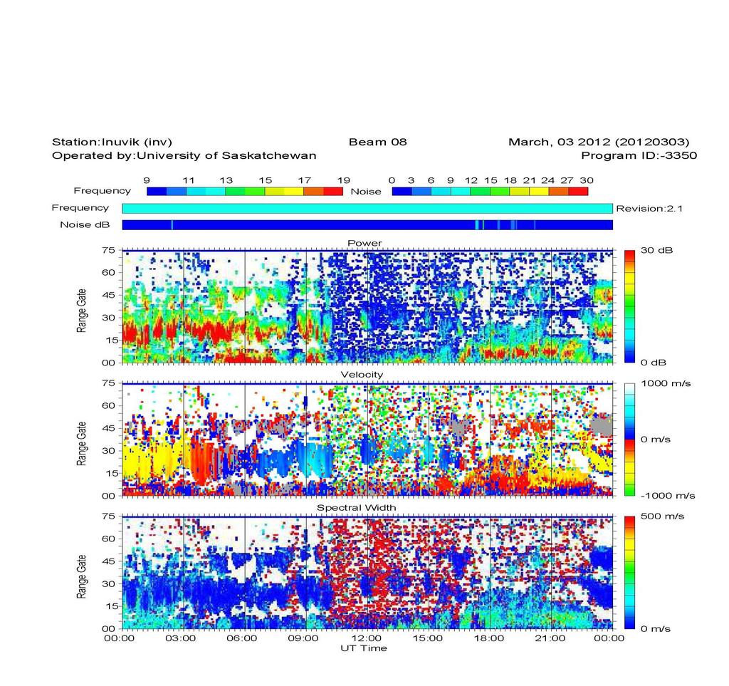
30 Range-time plots
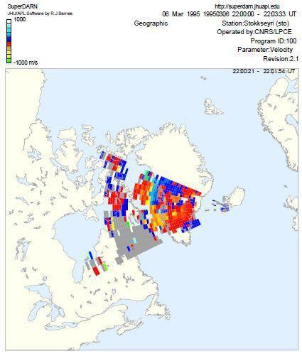
31 Field-of-view scan plots

32 You can only get directly measured vectors when two radars have an overlapping field of view AND both radars are seeing backscatter from the same geographical location. When these conditions are met that's when we have the highest quality data and the least ambiguity. Combining radars to get convection maps Restricting the global analysis of convection to directly overlapping observations eliminates a large amount of data.

33 Using Map Potential to get convection maps Map-Potential: makes use all the available data! Expand the polar cap potential in terms of spherical harmonics. Fit the complete set of line-of-sight velocities to determine the coefficients of the polar cap potential.
34 Example of result from Map Potential Convection maps are SuperDARN s most important product. The only experiment that can give a global snapshot of convection.

35 Coming up in Part 2: What can we do with SuperDARN radars?
Using the Radio Spectrum to Understand Space Weather
 Using the Radio Spectrum to Understand Space Weather Ray Greenwald Virginia Tech Topics to be Covered What is Space Weather? Origins and impacts Analogies with terrestrial weather Monitoring Space Weather
Dartmouth College SuperDARN Radars
 Dartmouth College SuperDARN Radars Under the guidance of Thayer School professor Simon Shepherd, a pair of backscatter radars were constructed in the desert of central Oregon over the Summer and Fall of
Mapping ionospheric backscatter measured by the SuperDARN HF radars Part 1: A new empirical virtual height model
 Ann. Geophys., 26, 823 84, 2008 European Geosciences Union 2008 Annales Geophysicae Mapping ionospheric backscatter measured by the SuperDARN HF radars Part : A new empirical virtual height model G. Chisham,
AGF-216. The Earth s Ionosphere & Radars on Svalbard
 AGF-216 The Earth s Ionosphere & Radars on Svalbard Katie Herlingshaw 07/02/2018 1 Overview Radar basics what, how, where, why? How do we use radars on Svalbard? What is EISCAT and what does it measure?
METR 3223, Physical Meteorology II: Radar Doppler Velocity Estimation
 METR 3223, Physical Meteorology II: Radar Doppler Velocity Estimation Mark Askelson Adapted from: Doviak and Zrnić, 1993: Doppler radar and weather observations. 2nd Ed. Academic Press, 562 pp. I. Essentials--Wave
The Role of Ground-Based Observations in M-I I Coupling Research. John Foster MIT Haystack Observatory
 The Role of Ground-Based Observations in M-I I Coupling Research John Foster MIT Haystack Observatory CEDAR/GEM Student Workshop Outline Some Definitions: Magnetosphere, etc. Space Weather Ionospheric
Determination of the correlation distance for spaced antennas on multipath HF links and implications for design of SIMO and MIMO systems.
 Determination of the correlation distance for spaced antennas on multipath HF links and implications for design of SIMO and MIMO systems. Hal J. Strangeways, School of Electronic and Electrical Engineering,
Radar Reprinted from "Waves in Motion", McGourty and Rideout, RET 2005
 Radar Reprinted from "Waves in Motion", McGourty and Rideout, RET 2005 What is Radar? RADAR (Radio Detection And Ranging) is a way to detect and study far off targets by transmitting a radio pulse in the
Radars: Powerful tools to study the Upper Atmosphere
 Radars: Powerful tools to study the Upper Atmosphere Jorge L. Chau 1 and Roger H. Varney 2 1 Radio Observatorio de Jicamarca, Instituto Geofísico del Perú, Lima 2 Electrical and Computer Engineering, Cornell
Radio wave power distribution at HF frequencies as modelled for the Radio Receiver Instrument (RRI) on the epop satellite mission
 on the epop satellite mission") Radio wave power distribution at HF frequencies as modelled for the Radio Receiver Instrument (RRI) on the epop satellite mission G. C. Hussey, R. G. Gillies, G. J. Sofko, and H. G. James SuperDARN Workshop
Radio wave power distribution at HF frequencies as modelled for the Radio Receiver Instrument (RRI) on the epop satellite mission G. C. Hussey, R. G. Gillies, G. J. Sofko, and H. G. James SuperDARN Workshop
Testing the Re-designed SuperDARN HF Radar and Modeling of a Twin Terminated Folded Dipole Array
 Testing the Re-designed SuperDARN HF Radar and Modeling of a Twin Terminated Folded Dipole Array Kevin Tyler Sterne Thesis submitted to the faculty of the Virginia Polytechnic Institute and State University
SODAR- sonic detecting and ranging
 Active Remote Sensing of the PBL Immersed vs. remote sensors Active vs. passive sensors RADAR- radio detection and ranging WSR-88D TDWR wind profiler SODAR- sonic detecting and ranging minisodar RASS RADAR
EISCAT_3D The next generation European Incoherent Scatter radar system Introduction and Brief Background
 EISCAT_3D The next generation European Incoherent Scatter radar system Introduction and Brief Background The high latitude environment is of increasing importance, not only for purely scientific studies,
EISCAT Experiments. Anders Tjulin EISCAT Scientific Association 2nd March 2017
 EISCAT Experiments Anders Tjulin EISCAT Scientific Association 2nd March 2017 Contents 1 Introduction 3 2 Overview 3 2.1 The radar systems.......................... 3 2.2 Antenna scan patterns........................
Automatically determining the origin direction and propagation mode of high-frequency radar backscatter
 RESEARCH ARTICLE 10.100/015RS005808 Key Points: HF radar backscatter returns from in front of and behind the radar Elevation angles are used to determine backscatter propagation path Interpretation of
Ray Tracing Analysis for the mid-latitude SuperDARN HF radar at Blackstone incorporating the IRI-2007 model
 Ray Tracing Analysis for the mid-latitude SuperDARN HF radar at Blackstone incorporating the IRI-2007 model Nitya Ravindran Varrier Thesis submitted to the faculty of the Virginia Polytechnic Institute
IONOSPHERE AND ATMOSPHERE RESEARCH WITH RADARS
 IONOSPHERE AND ATMOSPHERE RESEARCH WITH RADARS Jürgen Röttger, Max-Planck-Institut, Lindau, Germany published in UNESCO Encyclopedia of Life Support Systems (EOLSS), Geophysics and Geochemistry, 6.16.5.3,
Those DARN Radars: New Directions for the Super Dual Auroral Radar Network
 Those DARN Radars: New Directions for the Super Dual Auroral Radar Network Joseph B. H. Baker 1, J. M. Ruohoniemi 1, S. G. Shepherd 2, K. A. McWilliams 3, R. A. Greenwald 1, W. A. Bristow 4 1 Bradley Department
Impact of the low latitude ionosphere disturbances on GNSS studied with a three-dimensional ionosphere model
 Impact of the low latitude ionosphere disturbances on GNSS studied with a three-dimensional ionosphere model Susumu Saito and Naoki Fujii Communication, Navigation, and Surveillance Department, Electronic
Introduction to Ionospheric Radar Remote Sensing
 Introduction to Ionospheric Radar Remote Sensing John D Sahr Department of Electrical Engineering University of Washington CEDAR 2006 huge thanks to NSF for their support outline What is radar? Why use
How GNSS and Beacon receivers can be used to monitor auroral ionosphere and space weather?
 How GNSS and Beacon receivers can be used to monitor auroral ionosphere and space weather? Kirsti Kauristie, Finnish Meteorological Institute Special Thanks: J. Norberg (FMI), A. Aikio and T. Nygren (University
Measurements of doppler shifts during recent auroral backscatter events.
 Measurements of doppler shifts during recent auroral backscatter events. Graham Kimbell, G3TCT, 13 June 2003 Many amateurs have noticed that signals reflected from an aurora are doppler-shifted, and that
DOPPLER RADAR. Doppler Velocities - The Doppler shift. if φ 0 = 0, then φ = 4π. where
 Q: How does the radar get velocity information on the particles? DOPPLER RADAR Doppler Velocities - The Doppler shift Simple Example: Measures a Doppler shift - change in frequency of radiation due to
Study of small scale plasma irregularities. Đorđe Stevanović
 Study of small scale plasma irregularities in the ionosphere Đorđe Stevanović Overview 1. Global Navigation Satellite Systems 2. Space weather 3. Ionosphere and its effects 4. Case study a. Instruments
The EISCAT Heating Facility
 The EISCAT Heating Facility Michael Rietveld EISCAT Tromsø, Norway EISCAT radar school, 30 Aug-4 Sept, 2010, Sodankylä 1 Outline Description of the hardware Antenna beams Practical details- power levels
ISR Coordinated Science at Equatorial Latitudes
 ISR Coordinated Science at Equatorial Latitudes J. L. Chau 1, D. L. Hysell 2, and E. Kudeki 3 1 Radio Observatorio de Jicamarca, Instituto Geofísico del Perú, Lima 2 Earth and Atmospheric Sciences, Cornell
Multi-frequency observations of E-region HF radar aurora
 Annales Geophysicae (2003) 21: 761 777 c European Geosciences Union 2003 Annales Geophysicae Multi-frequency observations of E-region HF radar aurora S. E. Milan 1, M. Lester 1, and N. Sato 2 1 Department
Rec. ITU-R P RECOMMENDATION ITU-R P *
 Rec. ITU-R P.682-1 1 RECOMMENDATION ITU-R P.682-1 * PROPAGATION DATA REQUIRED FOR THE DESIGN OF EARTH-SPACE AERONAUTICAL MOBILE TELECOMMUNICATION SYSTEMS (Question ITU-R 207/3) Rec. 682-1 (1990-1992) The
Incoherent Scatter Radars Present, Past and Future. Bob Robinson Geospace Facilities Program National Science Foundation
 Incoherent Scatter Radars Present, Past and Future Bob Robinson Geospace Facilities Program National Science Foundation 3. It is difficult to imagine an area of space science research that does not benefit
Three-way validation of the Rankin Inlet PolarDARN radar velocity measurements
 Click Here for Full Article Three-way validation of the Rankin Inlet PolarDARN radar velocity measurements A. V. Koustov, 1 J.-P. St.-Maurice, 1 G. J. Sofko, 1 D. Andre, 1 J. W. MacDougall, 2 M. R. Hairston,
Precipitation of Energetic Protons from the Radiation Belts. using Lower Hybrid Waves
 Precipitation of Energetic Protons from the Radiation Belts using Lower Hybrid Waves Lower hybrid waves are quasi-electrostatic whistler mode waves whose wave normal direction is very close to the whistler
Ionospheric Propagation
 Ionospheric Propagation Page 1 Ionospheric Propagation The ionosphere exists between about 90 and 1000 km above the earth s surface. Radiation from the sun ionizes atoms and molecules here, liberating
ATMOSPHERIC NUCLEAR EFFECTS
 EC3630 Radiowave Propagation ATMOSPHERIC NUCLEAR EFFECTS by Professor David Jenn (version 1.1) 1 Atmospheric Nuclear Effects (1) The effect of a nuclear blast on the atmosphere is a complicated function
Set No.1. Code No: R
 Set No.1 IV B.Tech. I Semester Regular Examinations, November -2008 RADAR SYSTEMS ( Common to Electronics & Communication Engineering and Electronics & Telematics) Time: 3 hours Max Marks: 80 Answer any
Modern radio techniques
 Modern radio techniques for probing the ionosphere Receiver, radar, advanced ionospheric sounder, and related techniques Cesidio Bianchi INGV - Roma Italy Ionospheric properties related to radio waves
THE NATURE OF GROUND CLUTTER AFFECTING RADAR PERFORMANCE MOHAMMED J. AL SUMIADAEE
 International Journal of Electronics, Communication & Instrumentation Engineering Research and Development (IJECIERD) ISSN(P): 2249-684X; ISSN(E): 2249-7951 Vol. 6, Issue 2, Apr 2016, 7-14 TJPRC Pvt. Ltd.
ERAD Proceedings of ERAD (2004): c Copernicus GmbH J. Pirttilä 1, M. Lehtinen 1, A. Huuskonen 2, and M.
: c Copernicus GmbH J. Pirttilä 1, M. Lehtinen 1, A. Huuskonen 2, and M.") Proceedings of ERAD (24): 56 61 c Copernicus GmbH 24 ERAD 24 A solution to the range-doppler dilemma of weather radar measurements by using the SMPRF codes, practical results and a comparison with operational
Proceedings of ERAD (24): 56 61 c Copernicus GmbH 24 ERAD 24 A solution to the range-doppler dilemma of weather radar measurements by using the SMPRF codes, practical results and a comparison with operational
Scalable Ionospheric Analyser SIA 24/6
 Scalable Ionospheric Analyser SIA 24/6 Technical Overview Functional description The ATRAD Scalable Ionospheric Analyser SIA24/6 is designed to observe ionospheric irregularities and their drift in the
Radar for Atmosphere and Ionosphere Study
 ISELION 2018 Bandung, Indonesia March 5-9, 2018 Radar for Atmosphere and Ionosphere Study Mamoru Yamamoto (RISH, Kyoto University) Outline Introduction MU radar Scattering sources Radar principle Some
Plasma Turbulence of Non-Specular Trail Plasmas as Measured by a High Power Large Aperture Radar
 Space Environment and Satellite Systems Plasma Turbulence of Non-Specular Trail Plasmas as Measured by a High Power Large Aperture Radar Jonathan Yee and Sigrid Close Stanford University January 9, 2013
The Ionosphere and Thermosphere: a Geospace Perspective
 The Ionosphere and Thermosphere: a Geospace Perspective John Foster, MIT Haystack Observatory CEDAR Student Workshop June 24, 2018 North America Introduction My Geospace Background (Who is the Lecturer?
Multi-Path Fading Channel
 Instructor: Prof. Dr. Noor M. Khan Department of Electronic Engineering, Muhammad Ali Jinnah University, Islamabad Campus, Islamabad, PAKISTAN Ph: +9 (51) 111-878787, Ext. 19 (Office), 186 (Lab) Fax: +9
UNIT Derive the fundamental equation for free space propagation?
 UNIT 8 1. Derive the fundamental equation for free space propagation? Fundamental Equation for Free Space Propagation Consider the transmitter power (P t ) radiated uniformly in all the directions (isotropic),
First measurements of radar coherent scatter by the Radio Aurora Explorer CubeSat
 GEOPHYSICAL RESEARCH LETTERS, VOL. 39,, doi:10.1029/2012gl052249, 2012 First measurements of radar coherent scatter by the Radio Aurora Explorer CubeSat H. Bahcivan, 1 J. W. Cutler, 2 M. Bennett, 3 B.
Radio Waves in the Ionosphere
 Radio Waves in the Ionosphere E. S. Geospace and Earth Science Group Johns Hopkins University Applied Physics Laboratory 24 June 2012 Introduction Scope History Ionospheric propagation Ionospheric irregularities
Future of the HAARP Facility. Bob McCoy Director, Geophysical Institute University of Alaska Fairbanks
 Future of the HAARP Facility Bob McCoy Director, Geophysical Institute University of Alaska Fairbanks rpmccoy@alaska.edu 1 US Chairmanship 2015-2017 Future Space Research in Alaska: Integrated networks
Existing and future networks of ionospheric radars in polar regions &
 Existing and future networks of ionospheric radars in polar regions & EoI#159:ISPAM EISCAT Scientific Association Existing networks SuperDarn Middle atmosphere radars Incoherent Scatter Radars SuperDARN
Remote Sensing: John Wilkin IMCS Building Room 211C ext 251. Active microwave systems (1) Satellite Altimetry
 Satellite Altimetry") Remote Sensing: John Wilkin wilkin@marine.rutgers.edu IMCS Building Room 211C 732-932-6555 ext 251 Active microwave systems (1) Satellite Altimetry Active microwave instruments Scatterometer (scattering
Remote Sensing: John Wilkin wilkin@marine.rutgers.edu IMCS Building Room 211C 732-932-6555 ext 251 Active microwave systems (1) Satellite Altimetry Active microwave instruments Scatterometer (scattering
Channel. Muhammad Ali Jinnah University, Islamabad Campus, Pakistan. Multi-Path Fading. Dr. Noor M Khan EE, MAJU
 Instructor: Prof. Dr. Noor M. Khan Department of Electronic Engineering, Muhammad Ali Jinnah University, Islamabad Campus, Islamabad, PAKISTAN Ph: +9 (51) 111-878787, Ext. 19 (Office), 186 (Lab) Fax: +9
RADAR DEVELOPMENT BASIC CONCEPT OF RADAR WAS DEMONSTRATED BY HEINRICH. HERTZ VERIFIED THE MAXWELL RADAR.
 1 RADAR WHAT IS RADAR? RADAR (RADIO DETECTION AND RANGING) IS A WAY TO DETECT AND STUDY FAR OFF TARGETS BY TRANSMITTING A RADIO PULSE IN THE DIRECTION OF THE TARGET AND OBSERVING THE REFLECTION OF THE
Final Examination. 22 April 2013, 9:30 12:00. Examiner: Prof. Sean V. Hum. All non-programmable electronic calculators are allowed.
 UNIVERSITY OF TORONTO FACULTY OF APPLIED SCIENCE AND ENGINEERING The Edward S. Rogers Sr. Department of Electrical and Computer Engineering ECE 422H1S RADIO AND MICROWAVE WIRELESS SYSTEMS Final Examination
SCATTERING POLARIMETRY PART 1. Dr. A. Bhattacharya (Slide courtesy Prof. E. Pottier and Prof. L. Ferro-Famil)
") SCATTERING POLARIMETRY PART 1 Dr. A. Bhattacharya (Slide courtesy Prof. E. Pottier and Prof. L. Ferro-Famil) 2 That s how it looks! Wave Polarisation An electromagnetic (EM) plane wave has time-varying
SCATTERING POLARIMETRY PART 1 Dr. A. Bhattacharya (Slide courtesy Prof. E. Pottier and Prof. L. Ferro-Famil) 2 That s how it looks! Wave Polarisation An electromagnetic (EM) plane wave has time-varying
RADAR is the acronym for Radio Detection And Ranging. The. radar invention has its roots in the pioneering research during
 1 1.1 Radar General Introduction RADAR is the acronym for Radio Detection And Ranging. The radar invention has its roots in the pioneering research during nineteen twenties by Sir Edward Victor Appleton
Active microwave systems (1) Satellite Altimetry
 Satellite Altimetry") Remote Sensing: John Wilkin Active microwave systems (1) Satellite Altimetry jwilkin@rutgers.edu IMCS Building Room 214C 732-932-6555 ext 251 Active microwave instruments Scatterometer (scattering from
Remote Sensing: John Wilkin Active microwave systems (1) Satellite Altimetry jwilkin@rutgers.edu IMCS Building Room 214C 732-932-6555 ext 251 Active microwave instruments Scatterometer (scattering from
Scientific Studies of the High-Latitude Ionosphere with the Ionosphere Dynamics and ElectroDynamics - Data Assimilation (IDED-DA) Model
 Model") DISTRIBUTION STATEMENT A. Approved for public release; distribution is unlimited. Scientific Studies of the High-Latitude Ionosphere with the Ionosphere Dynamics and ElectroDynamics - Data Assimilation
DISTRIBUTION STATEMENT A. Approved for public release; distribution is unlimited. Scientific Studies of the High-Latitude Ionosphere with the Ionosphere Dynamics and ElectroDynamics - Data Assimilation
A Bistatic HF Radar for Current Mapping and Robust Ship Tracking
 A Bistatic HF Radar for Current Mapping and Robust Ship Tracking D. B. Trizna Imaging Science Research, Inc. 6103B Virgo Court Burke, VA, 22015 USA Abstract- A bistatic HF radar has been developed for
ATS 351 Lecture 9 Radar
 ATS 351 Lecture 9 Radar Radio Waves Electromagnetic Waves Consist of an electric field and a magnetic field Polarization: describes the orientation of the electric field. 1 Remote Sensing Passive vs Active
 Page 1 of 8 Search Contact NRL Personnel Locator Human Resources Public Affairs Office Visitor Info Planning a Visit Directions Maps Weather & Traffic Field Sites Stennis Monterey VXS-1 Chesapeake Bay
AN INTRODUCTION TO VHF/ UHF PROPAGATION. Paul Wilton, M1CNK
 AN INTRODUCTION TO VHF/ UHF PROPAGATION Paul Wilton, M1CNK OVERVIEW Introduction Propagation Basics Propagation Modes Getting Started in 2m DX INTRODUCTION QRV on 2m SSB since Aug 1998, on 6m since Jan
MWA Ionospheric Science Opportunities Space Weather Storms & Irregularities (location location location) John Foster MIT Haystack Observatory
 John Foster MIT Haystack Observatory") MWA Ionospheric Science Opportunities Space Weather Storms & Irregularities (location location location) John Foster MIT Haystack Observatory Storm Enhanced Density: Longitude-specific Ionospheric Redistribution
MWA Ionospheric Science Opportunities Space Weather Storms & Irregularities (location location location) John Foster MIT Haystack Observatory Storm Enhanced Density: Longitude-specific Ionospheric Redistribution
Refractive index effects on the scatter volume location and Doppler velocity estimates of ionospheric HF backscatter echoes
 Ann. Geophys., 27, 4207 4219, 2009 Author(s) 2009. This work is distributed under the Creative Commons Attribution 3.0 License. Annales Geophysicae Refractive index effects on the scatter volume location
Polarization. Contents. Polarization. Types of Polarization
 Contents By Kamran Ahmed Lecture # 7 Antenna polarization of satellite signals Cross polarization discrimination Ionospheric depolarization, rain & ice depolarization The polarization of an electromagnetic
Ionospheric Structure Imaging with ALOS PALSAR
 The Second ALOS PI Symposium Rhodes, Greece November 3 7, 008 Ionospheric Structure Imaging with ALOS PALSAR PI Number: 37 JAXA-RA PI: Jong-Sen Lee, Thomas L. Ainsworth and Kun-Shan Chen CSRSR, National
4/18/2012. Supplement T3. 3 Exam Questions, 3 Groups. Amateur Radio Technician Class
 Amateur Radio Technician Class Element 2 Course Presentation ti ELEMENT 2 SUB-ELEMENTS Technician Licensing Class Supplement T3 Radio Wave Characteristics 3 Exam Questions, 3 Groups T1 - FCC Rules, descriptions
1. Terrestrial propagation
 Rec. ITU-R P.844-1 1 RECOMMENDATION ITU-R P.844-1 * IONOSPHERIC FACTORS AFFECTING FREQUENCY SHARING IN THE VHF AND UHF BANDS (30 MHz-3 GHz) (Question ITU-R 218/3) (1992-1994) Rec. ITU-R PI.844-1 The ITU
2 INTRODUCTION TO GNSS REFLECTOMERY
 2 INTRODUCTION TO GNSS REFLECTOMERY 2.1 Introduction The use of Global Navigation Satellite Systems (GNSS) signals reflected by the sea surface for altimetry applications was first suggested by Martín-Neira
Kalman Tracking and Bayesian Detection for Radar RFI Blanking
 Kalman Tracking and Bayesian Detection for Radar RFI Blanking Weizhen Dong, Brian D. Jeffs Department of Electrical and Computer Engineering Brigham Young University J. Richard Fisher National Radio Astronomy
Structure of the Lecture
 Structure of the Lecture Chapter 2 Technical Basics: Layer 1 Methods for Medium Access: Layer 2 Representation of digital signals on an analogous medium Signal propagation Characteristics of antennas Chapter
Technician License Course Chapter 4
 Technician License Course Chapter 4 Propagation, Basic Antennas, Feed lines & SWR K0NK 26 Jan 18 The Antenna System Antenna: Facilitates the sending of your signal to some distant station. Feed line: Connects
6.014 Lecture 6: Multipath, Arrays, and Frequency Reuse
 6.014 Lecture 6: Multipath, Arrays, and Frequency Reuse A. Superposition of phasors This lecture focuses on the superposition of duplicate waves at receivers, where the multiplicity of waves may have originated
Remote Sensing: John Wilkin IMCS Building Room 211C ext 251. Active microwave systems (1) Satellite Altimetry
 Satellite Altimetry") Remote Sensing: John Wilkin wilkin@marine.rutgers.edu IMCS Building Room 211C 732-932-6555 ext 251 Active microwave systems (1) Satellite Altimetry Active microwave instruments Scatterometer (scattering
Remote Sensing: John Wilkin wilkin@marine.rutgers.edu IMCS Building Room 211C 732-932-6555 ext 251 Active microwave systems (1) Satellite Altimetry Active microwave instruments Scatterometer (scattering
Digital Sounder: HF Diagnostics Module:Ionosonde Dual Channel ( ) Eight Channel ( )
 Eight Channel ( )") CENTER FOR REMOTE SE NSING, INC. Digital Sounder: HF Diagnostics Module:Ionosonde Dual Channel (001-2000) Eight Channel (004-2006) 2010 Center for Remote Sensing, Inc. All specifications subject to change
CENTER FOR REMOTE SE NSING, INC. Digital Sounder: HF Diagnostics Module:Ionosonde Dual Channel (001-2000) Eight Channel (004-2006) 2010 Center for Remote Sensing, Inc. All specifications subject to change
Incoherent Scatter Experiment Parameters
 Incoherent Scatter Experiment Parameters At a fundamental level, we must select Waveform type Inter-pulse period (IPP) or pulse repetition frequency (PRF) Our choices will be dictated by the desired measurement
Radar interferometric imaging for the EISCAT Svalbard Radar
 Radar interferometric imaging for the EISCAT Svalbard Radar Tom Grydeland 1,2 Jorge L. Chau 3 César La Hoz 1 1 Department of Physics, University of Tromsø 2 Currently at the University Centre on Svalbard
EENG473 Mobile Communications Module 3 : Week # (12) Mobile Radio Propagation: Small-Scale Path Loss
 Mobile Radio Propagation: Small-Scale Path Loss") EENG473 Mobile Communications Module 3 : Week # (12) Mobile Radio Propagation: Small-Scale Path Loss Introduction Small-scale fading is used to describe the rapid fluctuation of the amplitude of a radio
EENG473 Mobile Communications Module 3 : Week # (12) Mobile Radio Propagation: Small-Scale Path Loss Introduction Small-scale fading is used to describe the rapid fluctuation of the amplitude of a radio
The USU-GAIM Data Assimilation Models for Ionospheric Specifications and Forecasts
 The USU-GAIM Data Assimilation Models for Ionospheric Specifications and Forecasts L. Scherliess, R. W. Schunk, L. C. Gardner, L. Zhu, J.V. Eccles and J.J Sojka Center for Atmospheric and Space Sciences
A bluffer s guide to Radar
 A bluffer s guide to Radar Andy French December 2009 We may produce at will, from a sending station, an electrical effect in any particular region of the globe; (with which) we may determine the relative
Lecture 12: Curvature and Refraction Radar Equation for Point Targets (Rinehart Ch3-4)
") MET 4410 Remote Sensing: Radar and Satellite Meteorology MET 5412 Remote Sensing in Meteorology Lecture 12: Curvature and Refraction Radar Equation for Point Targets (Rinehart Ch3-4) Radar Wave Propagation
MET 4410 Remote Sensing: Radar and Satellite Meteorology MET 5412 Remote Sensing in Meteorology Lecture 12: Curvature and Refraction Radar Equation for Point Targets (Rinehart Ch3-4) Radar Wave Propagation
HF AURORAL BACKSCATTER FROM THE E AND F REGIONS
 HF AURORAL BACKSCATTER FROM THE E AND F REGIONS A THESIS SUBMITTED TO THE COLLEGE OF GRADUATE STUDIES AND RESEARCH IN PARTIAL FULFILLMENT OF THE REQUIREMENTS FOR THE DEGREE OF DOCTOR OF PHILOSOPHY IN THE
Groundwave Propagation, Part One
 Groundwave Propagation, Part One 1 Planar Earth groundwave 2 Planar Earth groundwave example 3 Planar Earth elevated antenna effects Levis, Johnson, Teixeira (ESL/OSU) Radiowave Propagation August 17,
Active Cancellation Algorithm for Radar Cross Section Reduction
 International Journal of Computational Engineering Research Vol, 3 Issue, 7 Active Cancellation Algorithm for Radar Cross Section Reduction Isam Abdelnabi Osman, Mustafa Osman Ali Abdelrasoul Jabar Alzebaidi
Lecture Note on Wireless Communication Engineering I
 Lecture Note on Wireless Communication Engineering I Prof. Kiyomichi Araki Department of Electrical & Electronics Tokyo Institute of Technology South III Bld. Room No. 912 TEL/FAX: 03-5734-3495 E-mail:
Daily and seasonal variations of TID parameters over the Antarctic Peninsula
 Daily and seasonal variations of TID parameters over the Antarctic Peninsula A. Zalizovski 1, Y. Yampolski 1, V. Paznukhov 2, E. Mishin 3, A. Sopin 1 1. Institute of Radio Astronomy, National Academy of
Ship echo discrimination in HF radar sea-clutter
 Ship echo discrimination in HF radar sea-clutter A. Bourdillon (), P. Dorey () and G. Auffray () () Université de Rennes, IETR/UMR CNRS 664, Rennes Cedex, France () ONERA, DEMR/RHF, Palaiseau, France.
Effects of magnetic storms on GPS signals
 Effects of magnetic storms on GPS signals Andreja Sušnik Supervisor: doc.dr. Biagio Forte Outline 1. Background - GPS system - Ionosphere 2. Ionospheric Scintillations 3. Experimental data 4. Conclusions
The Precision Expandable Radar Calibration Sphere (PERCS) With Applications for Laser Imaging and Ranging
 With Applications for Laser Imaging and Ranging") The Precision Expandable Radar Calibration Sphere (PERCS) With Applications for Laser Imaging and Ranging Paul A. Bernhardt 1, Andy Nicholas 2, Linda Thomas 3, Mark Davis 3 1 Plasma Physics Division, 2
The Precision Expandable Radar Calibration Sphere (PERCS) With Applications for Laser Imaging and Ranging Paul A. Bernhardt 1, Andy Nicholas 2, Linda Thomas 3, Mark Davis 3 1 Plasma Physics Division, 2
Rec. ITU-R F RECOMMENDATION ITU-R F *
 Rec. ITU-R F.162-3 1 RECOMMENDATION ITU-R F.162-3 * Rec. ITU-R F.162-3 USE OF DIRECTIONAL TRANSMITTING ANTENNAS IN THE FIXED SERVICE OPERATING IN BANDS BELOW ABOUT 30 MHz (Question 150/9) (1953-1956-1966-1970-1992)
A Bistatic HF Radar for Current Mapping and Robust Ship Tracking
 A Bistatic HF Radar for Current Mapping and Robust Ship Tracking Dennis Trizna Imaging Science Research, Inc. V. 703-801-1417 dennis @ isr-sensing.com www.isr-sensing.com Objective: Develop methods for
Hermanus Magnetic Observatory (HMO)
") Hermanus Magnetic Observatory (HMO) As a Space Physics facility in Africa Presented by Danie Gouws & Elda Saunderson The HMO in a nutshell... The Hermanus Magnetic Observatory (HMO) is a national facility
Hermanus Magnetic Observatory (HMO) As a Space Physics facility in Africa Presented by Danie Gouws & Elda Saunderson The HMO in a nutshell... The Hermanus Magnetic Observatory (HMO) is a national facility
Contents. Contents. Contents. Lecture Note on Wireless Communication Engineering I. Wireless Communication Engineering 1
 Lecture Note on Wireless Communication Engineering I Prof. Kiyomichi Araki Department of Electrical & Electronics Tokyo Institute of Technology South III Bld. Room No. 91 TEL/FAX: +81-3-5734-3495 E-mail:
Regional ionospheric disturbances during magnetic storms. John Foster
 Regional ionospheric disturbances during magnetic storms John Foster Regional Ionospheric Disturbances John Foster MIT Haystack Observatory Regional Disturbances Meso-Scale (1000s km) Storm Enhanced Density
RECOMMENDATION ITU-R S *
 Rec. ITU-R S.1339-1 1 RECOMMENDATION ITU-R S.1339-1* Rec. ITU-R S.1339-1 SHARING BETWEEN SPACEBORNE PASSIVE SENSORS OF THE EARTH EXPLORATION-SATELLITE SERVICE AND INTER-SATELLITE LINKS OF GEOSTATIONARY-SATELLITE
First Results from the 2014 Coordinated Measurements Campaign with HAARP and CASSIOPE/ePOP
 First Results from the 2014 Coordinated Measurements Campaign with HAARP and CASSIOPE/ePOP Carl L. Siefring, Paul A. Bernhardt, Stanley J. Briczinski, and Michael McCarrick Naval Research Laboratory Matthew
Jicamarca Radio Observatory: 50 years of scientific and engineering achievements
 Jicamarca Radio Observatory: 50 years of scientific and engineering achievements Jorge L. Chau, David L. Hysell and Marco A. Milla Radio Observatorio de Jicamarca, Instituto Geofísico del Perú, Lima Outline
Estimation of Pulse Repetition Frequency for Ionospheric Communication
 International Journal of Electronics and Communication Engineering. ISSN 0974-266 Volume 4, Number 3 (20), pp. 25-258 International Research Publication House http:www.irphouse.com Estimation of Pulse
Illinois State Water Survey Division
 Illinois State Water Survey Division CLIMATE & METEOROLOGY SECTION SWS Contract Report 472. A STUDY OF GROUND CLUTTER SUPPRESSION AT THE CHILL DOPPLER WEATHER RADAR Prepared with the support of National
RECOMMENDATION ITU-R S.1341*
 Rec. ITU-R S.1341 1 RECOMMENDATION ITU-R S.1341* SHARING BETWEEN FEEDER LINKS FOR THE MOBILE-SATELLITE SERVICE AND THE AERONAUTICAL RADIONAVIGATION SERVICE IN THE SPACE-TO-EARTH DIRECTION IN THE BAND 15.4-15.7
Modeling of Ionospheric Refraction of UHF Radar Signals at High Latitudes
 Modeling of Ionospheric Refraction of UHF Radar Signals at High Latitudes Brenton Watkins Geophysical Institute University of Alaska Fairbanks USA watkins@gi.alaska.edu Sergei Maurits and Anton Kulchitsky
Australian Wind Profiler Network and Data Use in both Operational and Research Environments
 Australian Wind Profiler Network and Data Use in both Operational and Research Environments Bronwyn Dolman 1,2 and Iain Reid 1,2 1 ATRAD Pty Ltd 20 Phillips St Thebarton South Australia www.atrad.com.au
Ionospheric Propagation
 Ionospheric Nick Massey VA7NRM 1 Electromagnetic Spectrum Radio Waves are a form of Electromagnetic Radiation Visible Light is also a form of Electromagnetic Radiation Radio Waves behave a lot like light