Moku:Lab. Specifications. Revision Last updated 15 th April, 2018.
|
|
|
- Georgina Stanley
- 5 years ago
- Views:
Transcription


1 Moku:Lab Specifications Revision Last updated 15 th April, 2018.
2 Table of Contents Hardware 4 Specifications... 4 Analog I/O... 4 External trigger input... 4 Clock reference... 4 General characteristics... 5 General connectivity... 6 Hardware measurements... 7 ADC input noise... 7 ADC crosstalk... 8 Arbitrary Waveform Generator 10 Description Specifications Common characteristics Waveform characteristics Bode Analyzer 13 Description Specifications Source Input Measurement Saving Data Data Logger 16 Description Specifications Input Logging Digital Filter Box 18 Description...18 Specifications Inputs Filter characteristics Selecting the right IIR filter FIR Filter Builder 21 Description Specifications Inputs Filter characteristics Lock-In Amplifier 24 Description Specifications Signal channel Reference oscillator Moku:Lab Specifications rev Rights Reserved 2018
3 Signal output Saving Data Oscilloscope 27 Description Specifications Vertical characteristics Horizontal characteristics Trigger Measurements Phasemeter 31 Description Specifications Inputs Measurement Saving Data Synthesizer PID Controller 34 Description Specifications Inputs Controller Spectrum Analyzer 36 Description Specifications Frequency Amplitude Synthesizer Waveform Generator 39 Description Specifications Common characteristics Waveform characteristics Modulation Revision History 44 3 Moku:Lab Specifications rev Rights Reserved 2018
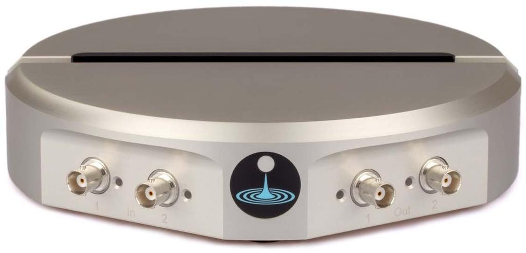
4 Hardware Specifications Analog I/O Analog inputs Channels Bandwidth (-3 db) Sampling rate Resolution Voltage range Input impedance Input coupling AC coupling corner (-3 db) SNR Input referred noise 2 (BNC) 200 MHz into 50 Ω 500 MS/s per channel 12-bit 1 V pp / 10 V pp 50 Ω / 1 MΩ AC / DC 100 Hz into 50 Ω 30 Hz into 1 MΩ 60 dbfs (per sample) 30 nv/ Hz above 100 khz Analog outputs Channels Bandwidth (-3 db) Sampling rate Resolution Voltage range Output impedance Output coupling 2 (BNC) >300 MHz 1 GS/s per channel 16-bit 2 V pp into 50 Ω 50 Ω DC External trigger input External trigger Trigger waveform Trigger bandwidth Trigger impedance Min trigger level Max trigger level Connector TTL compatible DC to 5 MHz Hi-Z 1.9 V 5 V BNC Clock reference On-board clock Frequency 10 MHz 4 Moku:Lab Specifications rev Rights Reserved 2018
5 On-board clock Stability < 500 ppb 10 MHz reference input Frequency Input impedance Input range Connector 10 MHz ± 250 khz 50 Ω -10 dbm to +10 dbm BNC 10 MHz reference output Output frequency Output level Connector 10 MHz -3 dbm BNC General characteristics General and environmental characteristics Power consumption Power voltage range 20 W typical 30 W when charging USB 100 to 240 V, 50/60 Hz Temperature Operating: 0 to +45 C Non-operating: -10 to +60 C Electromagnetic compliance Physical characteristics Dimensions Weight Security Diameter: 22 cm (8.66 in.) Height: 4.3 cm (1.70 in.) 1.69 kg (3.73 lbs) Kensington lock compatible 5 Moku:Lab Specifications rev Rights Reserved 2018
 6 Moku:Lab Specifications rev2018.")
6 General connectivity Connectivity Analog inputs Analog outputs Network USB network connection USB charge port SD card External trigger input 2 x BNC 2 x BNC Ethernet (10/100 Base-T) Wi-Fi b/g/n Micro-USB 10 W 16 GB class 10 supplied BNC 10 MHz clock reference input BNC 10 MHz clock reference output BNC DC Power 12 V (power module supplied) 6 Moku:Lab Specifications rev Rights Reserved 2018
7 Hardware measurements ADC input noise 7 Moku:Lab Specifications rev Rights Reserved 2018
8 ADC crosstalk 50 Ω // AC coupled // 0 db attenuation 8 Moku:Lab Specifications rev Rights Reserved 2018
9 1 MΩ // DC coupled // 20 db attenuation 9 Moku:Lab Specifications rev Rights Reserved 2018


10 Arbitrary Waveform Generator Description The Moku:Lab s Arbitrary Waveform Generator can generate custom waveforms with up to 65,000 points at update rates of up to 1 GS/s. Waveforms can be loaded from a file, or input as a piece-wise mathematical function with up to 32 segments. In pulsed mode, waveforms can be output with more than 250,000 cycles of dead time between pulses. Features Choose between one of the preset waveforms, load points from a file or input an equation directly Configure pulsed output with up to 250,000 cycles of dead time between pulses Phase-synchronized output between the two channels 10 Moku:Lab Specifications rev Rights Reserved 2018
11 Specifications Common characteristics Overview Channels 2 Bandwidth (-3 db) > 300 MHz into 50 Ω Sampling rate 1 GS/s per channel Output impedance 50 Ω Waveforms Sine, Gaussian, Exponential Fall, Sinc, Equation, Custom (from file) Amplitude Range Offset error 1 mv pp to 2 V pp into 50 Ω 1 GS/s per channel Resolution 100 µv Units V pp, dbm DC offset Range (peak AC + DC) Resolution 100 µv ± 1 V into 50 Ω ± 2 V into high-impedance Phase offset Range 0º to 360º Resolution 0.001º 11 Moku:Lab Specifications rev Rights Reserved 2018
12 Waveform characteristics Custom Maximum output rate 125 MS/s points Text file type Interpolation Minimum edge time Overshoot Jitter (cycle-to-cycle) Pulse width Period range 250 MS/s points 500 MS/s points 1 GS/s 8192 points Comma- or newline-delimited text Linear 2 ns 10% for edge times between 2 ns and 8 ns 2% for edge times greater than 8 ns < 1 ns 2 ns to period 1000 s to 10 ns 12 Moku:Lab Specifications rev Rights Reserved 2018


13 Description Bode Analyzer The Moku:Lab s Bode Analyzer can be used to measure the magnitude and phase of a system s transfer function using a swept sine output from 10 mhz to 120 MHz. Features Linear or logarithmic swept sine output Probe two systems simultaneously, or one system at two points Math channel to add, subtract, multiply or divide response functions as they are acquired See magnitude and phase on the interactive Bode plot Use cursors and markers to measure exact values on the plots Precisely adjust settling and averaging time to suit device under test Save a calibration trace to compare systems or compensate for cabling delays Easily save data and upload to the cloud 13 Moku:Lab Specifications rev Rights Reserved 2018
14 Specifications Source Source Waveform Frequency range Frequency resolution Sweep type Sine 10 mhz to 120 MHz 3.55 µhz Linear / Logarithmic Sweep points 32, 64, 128, 256, 512 Output amplitude range Source impedance ±0.5 mv to ±1 V into 50 Ω 50 Ω Input Input characteristics Input impedance Input coupling Input attenuation Input voltage range Input noise 50 Ω / 1 MΩ AC / DC 0 db / 20 db ± 0.5 V into 50 Ω with 0 db attenuation 30 nv/ Hz above 100 khz Flatness prior to normalization 10 mhz to 100 khz < 0.02 db into 50 Ω < 0.05 db into 1 MΩ Crosstalk 100 khz to 1 MHz < 0.02 db into 50 Ω < 0.03 db into 1 MΩ 1 MHz to 50 MHz < 0.3 db into 50 Ω < 0.7 db into 1 MΩ 1 MHz to 120 MHz < 0.7 db into 50 Ω < 2.2 db into 1 MΩ < 80 db at 50 Ω < 60 db at 1 MΩ 14 Moku:Lab Specifications rev Rights Reserved 2018
15 Measurement Measurement characteristics Settling time Min. Greater of 1 µs or 1 cycle Max seconds Averaging time Min. Greater of 1 µs or 1 cycle Noise-floor 100 ms averaging time 500 mv pp amplitude DC coupled input Normalized gain error Max seconds 10 mhz to 100 khz -100 db into 0 db attenuation -80 db into 20 db attenuation 100 khz to 1 MHz -125 db into 0 db attenuation -105 db into 20 db attenuation 1 MHz to 50 MHz -130 db into 0 db attenuation -110 db into 20 db attenuation 50 MHz to 120 MHz -120 db into 0 db attenuation -100 db into 20 db attenuation <0.05 db Normalized phase error < 0.5º Normalization Normalizes magnitude and phase using the most recent full sweep 1. Saving Data Saving data File formats Plain text: records data using a standard *.csv format Binary: records data using MathWorks *.mat format which can be opened using MATLAB Export modes SD Card, Dropbox, and icloud, My Files (ios 11) 1 The calibration feature can be used to isolate the magnitude and phase response of the system under test by compensating for deviations in magnitude and phase caused by cables and the Moku:Lab s own frequency response. 15 Moku:Lab Specifications rev Rights Reserved 2018


16 Description Data Logger The Moku:Lab Data Logger lets you log voltage data directly to an SD card for long-term measurements at rates of up to 100 ks/s. The duration is limited only by the capacity of the SD card. Data can also be acquired at up to 1 MS/s by saving directly to the Moku:Lab s 500 MB of internal storage. Data saved to the Moku:Lab s internal storage can be uploaded to the cloud at the end of the measurement. Features Record two channels of data at up to 100 ks/s to SD card and 1 MS/s to internal storage 16 Moku:Lab Specifications rev Rights Reserved 2018
17 Specifications Input Input characteristics Input voltage range Input impedance Input coupling ± 0.5 V into 50 Ω with 0 db attenuation 50 Ω / 1 MΩ AC / DC Logging Logging characteristics File formats Plain text: records data using a standard *.csv format Binary: records data using a proprietary *.li format for high-speed data logging. Note: data saved using the *.li format must be converted to plain text using the LI file converter available here: Export modes SD Card, Dropbox, and icloud, My Files (ios 11) Maximum sampling rate 1 MS/s into RAM (format: *.li binary) 100 ks/s into SD card (format: *.li binary) 20 ks/s into RAM / SD card (format: *.csv) Note: data saved to the Moku:Lab s on-board RAM will be lost when the device is rebooted. Delayed log start time Log duration Up to 240 hours 1 second up to 240 hours 17 Moku:Lab Specifications rev Rights Reserved 2018


18 Description Digital Filter Box The Moku:Lab s Digital Filter Box allows the user to interactively design and generate low-pass, high-pass, band-pass and band-stop filters with output sampling rates of 122 khz and MHz. Features Design your filter s frequency response using the interactive Bode plot Block diagram view of the digital signal processing with built-on probe points for signal monitoring Two inputs channels, two output channels with control matrix for blended inputs Supports custom filter designs 18 Moku:Lab Specifications rev Rights Reserved 2018
19 Specifications Inputs Input characteristics Channels 2 Input control matrix coefficients -20 to +20 Input impedance 50 Ω / 1 MΩ Input coupling AC / DC Input attenuation 0 db / 20 db Input voltage range ± 0.5 V into 50 Ω with 0 db attenuation Filter characteristics Pre-filter Input offset range ± 500 mv Input offset resolution 100 µv Input gain range -40 db to +40 db Input gain resolution 0.1 db Post-filter Output offset range ± 500 mv Output offset resolution 100 µv Output gain range -40 db to +40 db Output gain resolution 0.1 db General filter characteristics Filter shapes Sampling rates Filter types Passband ripple Stopband attenuation Zoom view Lowpass, Highpass, Bandpass, Bandstop, Custom 122 khz, MHz Butterworth, Chebyshev I, Chebyshev II, Elliptic, Bessel, Gaussian, Legendre 0.1 db to 10 db 10 db to 100 db Allows the user to zoom in on the filter s frequency response 19 Moku:Lab Specifications rev Rights Reserved 2018
20 Low-pass filter Filter order 2, 4, 6, 8 Low-pass corner frequency Hz to khz at 122 khz sampling rate Hz to MHz at MHz sampling rate High-pass filter Filter order 2, 4, 6, 8 High-pass corner frequency Hz to khz at 122 khz sampling rate Hz to MHz at MHz sampling rate Band-pass / band-stop filter Filter order 2, 4 Low corner frequency High corner frequency Minimum bandwidth Hz to khz at 122 khz sampling rate Hz to MHz at MHz sampling rate Hz to khz at 122 khz sampling rate Hz to MHz at MHz sampling rate 770 mhz at 122 khz sampling rate 100 Hz at MHz sampling rate Selecting the right IIR filter Filter type Butterworth Chebyshev I Chebyshev II Elliptical Bessel Gaussian Legendre Butterworth filters have a maximally flat passband and a monotonic frequency response, making them a good all-round filter type suitable for most applications. Chebyshev I filters have ripple in the passband but a sharper transition than Butterworth filters, making them useful for applications requiring aggressive stopband attenuation but can tolerate passband ripple between 0.1 db and 10 db. Chebyshev II filters have ripple in the stopband but a sharper transition than Butterworth filters, making them useful in applications requiring flat passbands and aggressive stopband attenuation. Elliptical (Cauer) filters have ripple in both passband and stopband, but also have the sharpest possible transition. Elliptical filters are useful in applications requiring extremely aggressive stopband attenuation. Bessel filters have maximally flat group and phase delay in the passband, thus preserving the wave shape of passband signals. Gaussian filters have the minimum possible group delay, and a step response with no overshoot and minimum rise and fall time. Legendre (Optimum L) filters have the sharpest possible transition while maintaining a monotonic frequency response. 20 Moku:Lab Specifications rev Rights Reserved 2018
.")

21 Description FIR Filter Builder Design and create advanced filters, all from an intuitive ipad interface, or with Python and MATLAB (LabVIEW coming soon). Features Design filters in the time domain or in the frequency domain, choosing from common impulse responses and window functions Load your own filter coefficients or enter an equation to create a customized impulse response Visualize the filter's transfer function, impulse and step response, or group and phase delay Easily save data and upload to the cloud 21 Moku:Lab Specifications rev Rights Reserved 2018
22 Specifications Inputs Input characteristics Channels 2 Input control matrix coefficients -20 to +20 Input impedance 50 Ω / 1 MΩ Input coupling AC / DC Input attenuation 0 db / 20 db Input voltage range ± 0.5 V into 50 Ω with 0 db attenuation Filter characteristics Pre-filter Input offset range ± 1 V Input offset resolution 100 µv Input gain range -40 db to +40 db Input gain resolution 0.1 db Post-filter Output offset range ± 2 V Output offset resolution 100 µv Output gain range -40 db to +40 db Output gain resolution 0.1 db General filter characteristics Sampling rates Number of coefficients Design domains khz, khz, khz, khz, MHz, MHz, MHz, MHz 2 to MHz 2 to MHz 2 to MHz 2 to MHz 2 to khz 2 to khz 2 to khz and khz Time (impulse response) Frequency (frequency response) 22 Moku:Lab Specifications rev Rights Reserved 2018
23 Filter design / configuration Display options Frequency response Impulse response Window Magnitude / Phase Impulse / Step Response Group / Phase Delay Lowpass, highpass. bandpass, bandstop Rectangular, Sinc, Triangular, Gaussian, Equation, Custom None, Bartlett, Hanning, Hamming, Blackman, Nuttall, Tukey, Kaiser Minimum filter cut-off frequency Sampling rate / 10,000 e.g., f min = khz Maximum filter cut-off frequency Sampling rate / 2 (approximately) e.g., f max = khz 23 Moku:Lab Specifications rev Rights Reserved 2018


24 Description Lock-In Amplifier The Moku:Lab s Lock-In Amplifier can be used to detect small oscillating signals that are obscured by noise. The intuitive user interface allows users to precisely configure the system and monitor its performance using probe points throughout the block diagram. Features Block diagram view of the digital signal processing with built-in probe points for signal monitoring Demodulate signals at frequencies of up to 200 MHz Measure signals obscured by noise with more than 80 db dynamic reserve 24 Moku:Lab Specifications rev Rights Reserved 2018
25 Specifications Signal channel Input characteristics Input coupling AC coupling corner (-3 db) Input impedance Input voltage range Input noise AC / DC 100 Hz into 50 Ω 30 Hz into 1 MΩ 50 Ω / 1 MΩ ± 5 V 30 nv/ Hz above 100 khz Demodulator Sources Types Input gain 2 Filter mode Filter cut-off frequency range Filter time-constant Filter slope Phase shift precision 0.001º Gain accuracy ± 1% Dynamic reserve PLL frequency range PLL bandwidth Internal Reference oscillator, Internal Auxiliary oscillator, External direct, External with phase-locked loop Internal, External with PLL: Sine (In-phase) / Cosine (Quadrature) External direct: Sine (In-phase) -20 db / 0 db / + 24 db / + 48 db Low-pass filter 237 mhz to 3.98 MHz 251 nanoseconds to seconds 6 db or 12 db per octave Better than 80 db 2 MHz to 200 MHz 10 khz Reference oscillator Reference and Auxiliary oscillators Waveform Frequency range Frequency resolution Distortion Sine 1 mhz to 200 MHz 3.55 µhz < -70 dbc for frequencies lower than 10 khz < -60 dbc for frequencies greater than 10 khz db and +48 db input gains are applied digitally and can be used to maximise the Lock-In Amplifier s dynamic range for weak input signals. 25 Moku:Lab Specifications rev Rights Reserved 2018
26 Signal output Output routing Output sources Output processing Direct, PID 3 Number of output channels 2 Polar-mode Gain profiles Controller frequency range Proportional gain Integrator crossover frequency Differentiator crossover frequency X, Y (cartesian mode); R, Θ (polar mode); Auxiliary Oscillator 0.8 V per cycle Proportional (P), integral (I), differential (D), integral saturation (IS), differential saturation (DS) 100 mhz to 10 MHz ± 60 db 1.00 Hz to 100 khz 10 Hz to 1 MHz Signal output Output voltage range (peak AC + DC) Gain range ±0.5 mv to ±1 V into 50 Ω -80 db to +80 db Saving Data Saving data File formats Maximum sampling rate Plain text: records data using a standard CSV format Binary: records data using a proprietary LI format for high-speed data logging. Note: data saved using the LI format must be converted to plain text using the LI file converter available here: 1 MS/s into RAM (format: *.li binary) (single channel) 500 ks/s into RAM (format: *.li binary) (two channels) 100 ks/s into SD card (format: *.li binary) 20 ks/s into RAM / SD card (format: *.csv) Note: data saved to the Moku:Lab s on-board RAM will be lost when the device is rebooted. Export modes SD Card, Dropbox, and icloud, My Files (ios 11) Delayed log start time Log duration Up to 240 hours 1 second up to 240 hours 3 Only one output may have a PID controller routing at a time 26 Moku:Lab Specifications rev Rights Reserved 2018


27 Description Oscilloscope The Moku:Lab s Oscilloscope features two analog input channels with 200 MHz bandwidth and independent control of AC/DC coupling and 50 Ω / 1 MΩ input impedance. The instrument s multitouch interface allows you to intuitively adjust timescales and voltage levels. Features Analyse two voltage channels with a vertical range of ±5 Volts and maximum sampling rate of 500 MS/s Input analog bandwidth of 200 MHz Synthesize sine, square, ramp, pulse, and DC waveforms Analyse signals in XY mode Quickly measure various waveform characteristics, trends and statistics 27 Moku:Lab Specifications rev Rights Reserved 2018
28 Specifications Vertical characteristics Voltage Channels 2 Input coupling Input bandwidth (-3 db) Input impedance Input voltage range Vertical resolution 4 Channel-to-channel isolation AC, DC > 200 MHz into 50 Ω 50 Ω, 1 MΩ ± 5 V 12 bits at 500 MS/s (ADC resolution) 13 bits at 125 MS/s 22 bits at 1 ks/s > 40 db Horizontal characteristics Time Time mode Horizontal range Normal, Roll 1 ns/div to 10 s/div Delay range Pre-trigger: 16 ksamples Greater of µs or screen width Post-trigger: 2 30 samples s to 1 Ms Acquisition Acquisition mode Normal, Precision 5 Maximum sampling rate Memory depth Averaging (linear) Persistence Interpolation 500 MS/s 16,384 Samples per channel 32.7 µs at 2 ns/div Off, 2 to 100 waveforms Off, 100 ms to 10 s, infinite Linear, SinX/X, Gaussian 4 Higher effective number of bits (ENOB) above the physical ADC specification is only available in precision mode. 5 Precision mode samples the waveform at the full rate and applies a finite impulse response (FIR) low-pass filter to attenuate noise above the usable bandwidth of the measurement sampling rate and prevent aliasing. 28 Moku:Lab Specifications rev Rights Reserved 2018
29 Trigger Trigger Trigger modes Auto: Triggers automatically after timeout (1 second if previously triggered, 0.05 seconds otherwise) Trigger sources Nth event Holdoff Trigger types Normal: Single: Triggers only on trigger event Triggers once on a trigger event. Press the play button to re-trigger Input 1, Input 2, Output 1, Output 2, External Trigger on the 1 st to 65,535 th event 1 nanosecond to 10 seconds Edge: Rising edge, falling edge, both edges Pulse: Positive / negative polarity 10.0 seconds > pulse width > nanoseconds Trigger sensitivity Sensitivity modes Auto: Automatically configures trigger sensitivity based on horizontal and vertical scales Select Noise Reject or high-frequency HF Reject options Manual modes Hysteresis Manual: Relative, Absolute Manually configure trigger sensitivity Relative: 0.01 div to 5.00 div Absolute: 100 µv to 5.00 V Measurements Measurements Time measurements Amplitude measurements Math Visualisations Frequency, period, duty cycle, positive pulse width, negative pulse width, rise time, fall time, rise rate, fall rate Peak-to-peak, amplitude, maximum, minimum, mean, cycle mean, RMS, cycle RMS, standard deviation, high-level, low-level, overshoot, undershoot Add, subtract, multiply, divide, XY mode, integrate, differentiate, FFT, min hold, max hold, arbitrary equation mode (using equation editor) Histogram, time trend Cursors Maximum voltage cursors Maximum time cursors Voltage cursor options User defined reference 5 per channel 5 per channel Manual, track mean, track maximum, track minimum, maximum hold, minimum hold A single cursor can be set as a reference for differential measurements using all other active cursors 29 Moku:Lab Specifications rev Rights Reserved 2018
30 Synthesizer Channels 2 Output impedance 50 Ω Waveforms 6 Sine, Square, Ramp, Pulse, DC Output frequency range Output voltage range 1 mhz to 250 MHz ± 1 V into 50 Ω 6 Modulation not available for waveforms synthesized using the oscilloscope instrument. 30 Moku:Lab Specifications rev Rights Reserved 2018


31 Description Phasemeter The Moku:Lab s Phasemeter can be used to measure the phase of oscillating input signals between 1 khz and 200 MHz with 1 µcycle precision. Features Measure the phase difference between two input signals with better than 1 µcycle precision Select between measuring phase, frequency and amplitude Acquire data at up to 125 ks/s Track frequency and phase disturbances at up to 10 khz 31 Moku:Lab Specifications rev Rights Reserved 2018
32 Specifications Inputs Input characteristics Input frequency range Input voltage range Input impedance Input coupling 1 khz to 200 MHz ± 0.5 V into 50 Ω 50 Ω / 1 MΩ AC / DC Measurement Measurement characteristics Freq. set-point precision 3.55 µhz Modes of operation Auto-acquire: Automatically determines input frequency Manual: Initializes the phasemeter to a user-defined frequency Tracking bandwidth 10 Hz / 40 Hz / 150 Hz / 600 Hz / 2.5 khz / 10 khz (user selectable) Frequency precision Input Frequency Precision (f = Fourier frequency) 1 khz to 10 MHz f x 10 µhz/ Hz from 1 mhz to 1 khz 10 MHz to 100 MHz f x 20 µhz/ Hz from 1 mhz to 1 khz > 100 MHz 20 µhz/ Hz below 1 Hz f x 20 µhz/ Hz from 1 Hz to 1 khz Phase precision 7 1 khz to 10 MHz 100 ncycles/ Hz above 1 Hz RMS 10 MHz to 100 MHz 2 µcycles/ Hz above 1 Hz > 100 MHz 20 µcycles/ Hz above 1 Hz 7 Frequency and phase measurement precision is limited by sampling jitter at low Fourier frequencies. 32 Moku:Lab Specifications rev Rights Reserved 2018
33 Saving Data Saving data Logging rates File formats Maximum sampling rate 30 S/s, 120 S/s, 490 S/s, 1.95 ks/s, 15.6 ks/s, 125 ks/s Plain text: records data using a standard CSV format Binary: records data using a proprietary LI format for high-speed data logging. Note: data saved using the LI format must be converted to plain text using the LI file converter available here: 1 MS/s into RAM (format: *.li binary) 100 ks/s into SD card (format: *.li binary) 20 ks/s into RAM / SD card (format: *.csv) Note: data saved to the Moku:Lab s on-board RAM will be lost when the device is rebooted. Export modes SD Card, Dropbox, and icloud, My Files (ios 11) Delayed log start time Log duration Up to 240 hours 1 second up to 240 hours Synthesizer Synthesizer 8 Channels 2 Output impedance 50 Ω Waveforms Sine Output modes Manual, input-locked Sampling rate 1 GS/s per channel Voltage range ± 1 V into 50 Ω 8 Where not stated, Phasemeter Synthesizer specifications match those of the Moku:WaveformGenerator instrument. 33 Moku:Lab Specifications rev Rights Reserved 2018


34 Description PID Controller The Moku:Lab s PID controller enables users to design and deploy a control system for a wide range of applications including temperature stabilization and laser frequency control. Features Design your control system s frequency response using the interactive Bode plot Block diagram view of the digital signal processing with built-in probe points for signal monitoring Two input channels and two output channels with control matrix for blending inputs Includes single or double integrators and differentiators with low- and high-frequency gain saturation Configure controller parameters in basic or advanced editing modes 34 Moku:Lab Specifications rev Rights Reserved 2018
35 Specifications Inputs Input characteristics Channels 2 Input control matrix coefficients (linear gain) Input impedance Input coupling Input attenuation Input voltage range -20 to Ω / 1 MΩ AC / DC 0 db / 20 db ± 0.5 V into 50 Ω with 0 db attenuation Controller General characteristics Gain profiles Maximum bandwidth 100 khz with a phase delay of 30 Input / output offset range Proportional (P), integral (I), differential (D), double-integral (I+), integral saturation (IS), differential saturation (DS) ± 1 V Offset precision 100 µv Gain characteristics Gain profiles Controller frequency range Input / output offset range Proportional (P), integral (I), differential (D), double-integral (I+), integral saturation (IS), differential saturation (DS) 100 mhz to 10 MHz ± 1 V Offset precision 100 µv Proportional gain Integrator crossover frequency Double integrator crossover frequency Integral saturation level Differentiator crossover frequency Differentiator saturation level ± 60 db 1.00 Hz to 100 khz 1.00 Hz to integrator crossover frequency Between proportional gain and +60 db The integrator saturation crossover frequency cannot be lower than 10 Hz 10.0 Hz to 1.00 MHz Between proportional gain and +60 db The differentiator saturation crossover frequency cannot be higher than 1 MHz 35 Moku:Lab Specifications rev Rights Reserved 2018

36 Description Spectrum Analyzer The Moku:Lab s spectrum analyzer enables users to analyze dynamic signals in the frequency domain from DC to 250 MHz. Features DC to 250 MHz frequency range 1 khz to 250 MHz frequency span Quickly measure key metrics by dragging measurement cursors onto features of interest using the ipad s multi-touch interface 36 Moku:Lab Specifications rev Rights Reserved 2018
37 Specifications Frequency Frequency Range Span DC to 250 MHz 1 khz to 250 MHz Resolution bandwidth (RBW) Modes Auto Automatically sets the RBW based on the current span and window function Windows Manual Min Allows the user to manually set the RBW within the limits tolerated by the span and window function Sets the RBW at the minimum possible value for the current span and window function The minimum RBW is 1 Hz None (uniform), Hanning, Flat Top, Blackman-Harris Amplitude Voltage Channels 2 Input coupling Input impedance Input attenuation Input bandwidth (-3 db) Input voltage range Input voltage sensitivity AC / DC 50 Ω / 1 MΩ 0 db / 20 db > 200 MHz into 50 Ω > 180 MHz into 1 MΩ ± 0.5 V into 50 Ω with 0 db attenuation ± 5 V into 50 Ω with 20 db attenuation -130 dbm with 0 db attenuation at minimum RBW Display Scales Volts, dbm Display modes Power, Power Spectral Density (PSD) Video bandwidth (VBW) 10 Hz to 2.4 MHz depending on span Averages 1 to 100 Persistence 100 ms to 10 s, infinite, off 37 Moku:Lab Specifications rev Rights Reserved 2018
38 Synthesizer Synthesizer Channels 2 Output impedance 50 Ω Waveforms 9 Sine Output frequency range Sweep mode Output voltage range 1 mhz to 250 MHz Sweeps the output frequency across the current span with a fixed sweep period of 5 seconds ± 1 V into 50 Ω 9 Modulation not available for waveforms synthesized using the oscilloscope instrument. 38 Moku:Lab Specifications rev Rights Reserved 2018


39 Description Waveform Generator The Moku:Lab s waveform generator can be used to generate two independent waveforms at up to 200 MHz with a voltage range of 2 V pp into a 50 Ω load. Waveforms can be modulated in amplitude, frequency and phase at frequencies of up to 62.5 MHz. Features Generate sine waves from 1 mhz to 250 MHz Generate square and ramp waves from 1 mhz up to 100 MHz Generate pulsed waveforms with a minimum pulse width of 10 ns at up to 100 MHz Modulate waveforms in amplitude, frequency and phase at up to 62.5 MHz using both internal and external sources 39 Moku:Lab Specifications rev Rights Reserved 2018
40 Specifications Common characteristics Overview Channels 2 Bandwidth (-3 db) 300 MHz into 50 Ω Sampling rate 1 GS/s per channel Output impedance 50 Ω Waveforms Sine, Square, Ramp, Pulse, DC Amplitude Range 1 mv pp to 2 V pp into 50 Ω Offset error < 500 µv into 50 Ω Resolution 100 µv Channel isolation > 40 db from DC to 200 MHz Units V pp, dbm DC offset Range (peak AC + DC) ± 1 V into 50 Ω Resolution 100 µv Phase offset Range 0º to 360º Resolution 0.001º Waveform characteristics Sine Frequency range 1 mhz to 250 MHz Amplitude flatness (into 50 Ω) < 100 khz < 0.03 db 100 khz to 10 MHz < 0.08 db 10 MHz to 250 MHz < 0.12 db Total harmonic distortion < 0.1% (1.5 MHz, 5 harmonics) SFDR > 50 dbc for frequencies less than 20 MHz 40 Moku:Lab Specifications rev Rights Reserved 2018
41 Square Frequency range Edge time 10 Overshoot Jitter (cycle-to-cycle) 1 mhz to 100 MHz < 2.3 ns into 50 Ω < 2.6 ns into 1 MΩ 10% for edge times between 2 ns and 8 ns 2% for edge times greater than 8 ns < 1 ns Ramp Frequency range Symmetry 11 1 mhz to 100 MHz 20% to 80% at 100 MHz 4% to 96% at 20 MHz 0% to 100% at 5 MHz Linearity Below 1 MHz > 99% Between 1 MHz and 50 MHz > 98% Above 50 MHz > 95% Pulse Frequency range Period range Pulse width Edge time Edge time resolution Overshoot Jitter 1 mhz to 100 MHz 1000 s to 10 ns 2 ns to period 2 ns to half the pulse width 1 ns < 2% for rise times greater than 8 ns < 15% for rise times between 2 ns and 8 ns Same as square wave Modulation Amplitude Carrier waveforms Sine, Square, Ramp, Pulse Source Internal, External Internal modulation Sine Frequency 1 mhz to 62.5 MHz Depth 0% to 100% Frequency Carrier waveforms Sine, Square, Pulse 10 Measured for a 2 Vpp square wave at 10 khz. 11 Symmetry is limited by the minimum rise time of 2 ns and number of harmonics required to maintain a linearity of more than 99%. 41 Moku:Lab Specifications rev Rights Reserved 2018
42 Frequency Source Internal modulation Frequency Deviation (carrier + deviation) Internal, External Sine DC to 62.5 MHz DC to 250 MHz Phase Carrier waveforms Sine, Square, Pulse Source Internal, External Internal modulation Sine Frequency DC to 62.5 MHz Phase shift 0.0º to 360.0º External Carrier waveforms Sine, Square, Ramp, Pulse Source Ch1: Input 1, Output 2 Ch2: Input 2, Output 1 Voltage range Frequency Variable deviation ± 1 V into 50 Ω DC to 62.5 MHz AM: %/V FM: Hz/V PM: º/V Burst Modes of Operation Start, N-Cycle, Gated N-Cycle range 1 to 1,000,000 Trigger Sources Nominal Trigger Level Ch1: Input 1, Output 2, External Ch2: Input 2, Output 1, External Input Channel: 1.8 V Output Channel: 0.5 V External: 1.2 V 42 Moku:Lab Specifications rev Rights Reserved 2018
43 Sweep Sweep Frequency Start/End Sweep Time Trigger Sources Nominal Trigger Level Sine: 1 mhz to 250 MHz Square, Ramp, Pulse: 1 mhz to 100 MHz 1 ms to 1 ks Ch1: Input 1, Output 2, External Ch2: Input 2, Output 1, External Input Channel: 1.8 V Output Channel: 0.5 V External: 1.2 V 43 Moku:Lab Specifications rev Rights Reserved 2018
44 Revision History Introduced FIR Filter Builder specifications Reorganised order of specifications Updated specifications Added instrument specifications for the FIR filter builder Order in which instrument specifications appear is now consistent with other material Updated specifications in line with feature upgrades in Moku:Lab release version Updated specification Updated spurious free dynamic range specification for frequencies lower than 20 MHz (old value was > 70 dbc, new value is > 50 dbc) Reformatted document Added table of contents Included hardware specifications Waveform Generator Oscilloscope Phasemeter Lock-in Amplifier Added Burst, Sweep modulation specifications Corrected frequency range text in instrument description Updated description of auto-mode triggering timeouts Added new output/logging rates Added synthesizer phase-locked functionality Added new demodulation source specifications Added new output routing and processing options Initial Revision This information is subject to change without notice Liquid Instruments. All Rights Reserved. 44 Moku:Lab Specifications rev Rights Reserved 2018
Moku:Lab. Specifications INSTRUMENTS. Moku:Lab, rev
 Moku:Lab L I Q U I D INSTRUMENTS Specifications Moku:Lab, rev. 2018.1 Table of Contents Hardware 4 Specifications 4 Analog I/O 4 External trigger input 4 Clock reference 5 General characteristics 5 General
Analog Arts SG985 SG884 SG834 SG814 Product Specifications [1]
![Analog Arts SG985 SG884 SG834 SG814 Product Specifications [1]](/thumbs/94/122371203.jpg "Analog Arts SG985 SG884 SG834 SG814 Product Specifications [1]") www.analogarts.com Analog Arts SG985 SG884 SG834 SG814 Product Specifications [1] 1. These models include: an oscilloscope, a spectrum analyzer, a data recorder, a frequency & phase meter, and an arbitrary
www.analogarts.com Analog Arts SG985 SG884 SG834 SG814 Product Specifications [1] 1. These models include: an oscilloscope, a spectrum analyzer, a data recorder, a frequency & phase meter, and an arbitrary
Analog Arts SF900 SF650 SF610 Product Specifications
 www.analogarts.com Analog Arts SF900 SF650 SF610 Product Specifications Analog Arts reserves the right to change, modify, add or delete portions of any one of its specifications at any time, without prior
Analog Arts SF990 SF880 SF830 Product Specifications
 1 www.analogarts.com Analog Arts SF990 SF880 SF830 Product Specifications Analog Arts reserves the right to change, modify, add or delete portions of any one of its specifications at any time, without
Analog Arts SL987 SL957 SL937 SL917 Product Specifications [1]
![Analog Arts SL987 SL957 SL937 SL917 Product Specifications [1]](/thumbs/95/126095980.jpg "Analog Arts SL987 SL957 SL937 SL917 Product Specifications [1]") www.analogarts.com Analog Arts SL987 SL957 SL937 SL917 Product Specifications [1] 1. These models include: an oscilloscope, a spectrum analyzer, a data recorder, a frequency & phase meter, an arbitrary
www.analogarts.com Analog Arts SL987 SL957 SL937 SL917 Product Specifications [1] 1. These models include: an oscilloscope, a spectrum analyzer, a data recorder, a frequency & phase meter, an arbitrary
Analog Arts AG900 AG885 AG875 AG815 Product Specifications
 www.analogarts.com Analog Arts AG900 AG885 AG875 AG815 Product Specifications Arbitrary Waveform Generator General ( Typical ) Specifications AG900 AG885 AG875 AG815 Arbitrary waveform length 2 to 64K
ArbStudio Arbitrary Waveform Generators
 ArbStudio Arbitrary Waveform Generators Key Features Outstanding performance with 16-bit, 1 GS/s sample rate and 2 Mpts/Ch 2 and 4 channel models Digital pattern generator PWM mode Sweep and burst modes
ArbStudio Arbitrary Waveform Generators. Powerful, Versatile Waveform Creation
 ArbStudio Arbitrary Waveform Generators Powerful, Versatile Waveform Creation UNMATCHED WAVEFORM UNMATCHED WAVEFORM GENERATION GENERATION Key Features 125 MHz bandwidth 1 GS/s maximum sample rate Long
WaveStation Function/Arbitrary Waveform Generators
 WaveStation Function/Arbitrary Waveform Generators Key Features High performance with 14-bit, 125 MS/s and 16 kpts 2 channels on all models Large 3.5 color display for easy waveform preview Over 40 built-in
WaveStation Function/Arbitrary Waveform Generators
 WaveStation Function/Arbitrary Waveform Generators Key Features High performance with 14-bit, 125 MS/s and 16 kpts 2 channels on all models Large 3.5 color display for easy waveform preview Over 40 built-in
WaveStation Function/Arbitrary Waveform Generators
 Function/Arbitrary Waveform Generators Key Features High performance with 14-bit waveform generation, up to 500 MS/s sample rate and up to 512 kpts memory 2 channels on all models Large color display for
Dual Channel Function/Arbitrary Waveform Generators 4050B Series
 Data Sheet Dual Channel Function/Arbitrary Waveform Generators The Dual Channel Function/ Arbitrary Waveform Generators are capable of generating stable and precise sine, square, triangle, pulse, and arbitrary
Chapter 13 Specifications
 RIGOL All the specifications can be guaranteed if the following two conditions are met unless where noted. The generator is within the calibration period and has performed self-calibration. The generator
MSO Supplied with a full SDK including example programs Software compatible with Windows XP, Windows Vista and Windows 7 Free Technical Support
 PicoScope 2205 MSO USB-POWERED MIXED SIGNAL OSCILLOSCOPE Think logically... 25 MHz analog bandwidth 100 MHz max. digital input frequency 200 MS/s mixed signal sampling Advanced digital triggers SDK and
DG4000 Series Waveform Generators
 No.1 DG4000 DG4000 series is a multifunctional generator that combines many functions in one, including Function Generator, Arbitrary Waveform Generator, Pulse Generator, Harmonic Generator, Analog/Digital
Racal Instruments. Product Information
 Racal Instruments 3172 200 MS/s Waveform Generator & Dual 50 MHz Pulse/ Timing Generator The, a 200 MS/s Waveform Generator and Dual 50 MHz Pulse and Timing Generator, combines multi-instrument density
DG5000 Series Specifications
 DG5000 Series Specifications All the specifications can be guaranteed if the following two conditions are met unless where noted. The generator is within the calibration period and has performed self-calibration.
Model MHz Arbitrary Waveform Generator Specifications
 50MHz Arbitrary Waveform Generator s DISPLAY: Graph mode for visual verification of signal settings. CAPABILITY: Standard waveforms: Sine, Square, Ramp, Triangle, Pulse, Noise, DC Built-in arbitrary waveforms:
Digital Storage Oscilloscopes Models 2540B, 2542B, 2540B-GEN, 2542B-GEN
 Data Sheet Digital Storage Oscilloscopes Models 2540B, 2542B, 2540B-GEN, 2542B-GEN The 2540B, 2542B, 2540B-GEN, and 2542B-GEN dual channel 60 MHz and 100 MHz digital storage oscilloscopes deliver performance
U1604A Handheld Oscilloscopes, 40 MHz
 Products & Services Technical Support Buy Industries About Agilent Search: All Test & Measurement Go United States Home >... > Oscilloscopes > U1600A Series handheld oscilloscopes (2 models) > U1604A Handheld
U1571A Ni-MH Battery Pack for U1600A Handheld Oscilloscopes
 United States Home >... > Oscilloscope Accessories > U1600 Series Oscilloscope Accessories > U1571A Ni-MH Battery Pack for U1600A Handheld Oscilloscopes Key Specifications Features Ni-MH Battery Pack,
RIGOL Data Sheet. DG3000 Series Function/Arbitrary Waveform Generator DG3121A, DG3101A, DG3061A. Product Overview. Easy to Use Design.
 RIGOL Data Sheet DG3000 Series Function/Arbitrary Waveform Generator DG3121A, DG3101A, DG3061A Product Overview DG3000 Series Function/Arbitrary Waveform Generators adopt DDS technology, which enables
RIGOL Data Sheet. DG2000 Series Function/Arbitrary Waveform Generator DG2041A, DG2021A. Product Overview. Main Features.
 RIGOL Data Sheet DG2000 Series Function/Arbitrary Waveform Generator DG2041A, DG2021A Product Overview DG2000 Series Function/Arbitrary Waveform Generators adopt DDS technology, which enables to generate
Dual Channel Function/Arbitrary Waveform Generators 4050 Series
 Data Sheet Dual Channel Function/Arbitrary Waveform Generators The Dual Channel Function/Arbitrary Waveform Generators are capable of generating stable and precise sine, square, triangle, pulse, and arbitrary
Models 296 and 295 combine sophisticated
 Established 1981 Advanced Test Equipment Rentals www.atecorp.com 800-404-ATEC (2832) Models 296 and 295 50 MS/s Synthesized Multichannel Arbitrary Waveform Generators Up to 4 Independent Channels 10 Standard
Output Impedance. Duty Cycle Range. Buffer Size Resolution. PROTECTION Input Over Voltage. Output Short Circuit. TRIGGERING Sources.
 3 Channel Digital Storage Oscilloscope (DSO) Instrument VERTICAL SPECIFICATIONS Analogue Bandwidth (-3dB) Bandwidth Limiting Rise time (10% to 90%, calculated) Input ranges (full scale) Input sensitivity
Function/Arbitrary Waveform Generator
 Distributed By: Signal Test, Inc 1529 Santiago Ridge Way San Diego, CA 92154 Tel. 1-619-575-1577 USA www.signaltestinc.com Sales@SignalTestInc.com DG1000ZSeries Function/Arbitrary Waveform Generator SiFi
DG5000 series Waveform Generators
 DG5000 series Waveform Generators DG5000 is a multifunctional generator that combines many functions in one, including Function Generator, Arbitrary Waveform Generator, IQ Baseband /IQ IF, Frequency Hopping
Characteristics. Frequency (DG1022) Sine, Square, Ramp, Triangle, Pulse, Noise, Arb. ±50 ppm in 90 days ±100 ppm in 1year 18 C ~ 28 C.
 Sine, Square, Ramp, Triangle, Pulse, Noise, Arb. ±50 ppm in 90 days ±100 ppm in 1year 18 C ~ 28 C.") Characteristics Frequency (DG1022) Waveforms Sine Square Ramp, Triangle Pulse Noise Arb Resolution Accuracy Temperature index Sine, Square, Ramp, Triangle, Pulse, Noise, Arb 1µHz ~ 20MHz 1µHz ~ 5MHz 1µHz
Characteristics Frequency (DG1022) Waveforms Sine Square Ramp, Triangle Pulse Noise Arb Resolution Accuracy Temperature index Sine, Square, Ramp, Triangle, Pulse, Noise, Arb 1µHz ~ 20MHz 1µHz ~ 5MHz 1µHz
Rigol DG1022A Function / Arbitrary Waveform Generator
 Rigol DG1022A Function / Arbitrary Waveform Generator The Rigol DG1000 series Dual-Channel Function/Arbitrary Waveform Generator adopts DDS (Direct Digital Synthesis) technology to provide stable, high-precision,
Impedance 50 (75 connectors via adapters)
") VECTOR NETWORK ANALYZER PLANAR 304/1 DATA SHEET Frequency range: 300 khz to 3.2 GHz Measured parameters: S11, S21, S12, S22 Dynamic range of transmission measurement magnitude: 135 db Measurement time
VECTOR NETWORK ANALYZER PLANAR 304/1 DATA SHEET Frequency range: 300 khz to 3.2 GHz Measured parameters: S11, S21, S12, S22 Dynamic range of transmission measurement magnitude: 135 db Measurement time
Arbitrary/Function Generators AFG3000C Series Datasheet
 Test Equipment Depot - 800.517.8431-99 Washington Street Melrose, MA 02176 - TestEquipmentDepot.com Arbitrary/Function Generators AFG3000C Series Datasheet Applications Electronic test and design Sensor
SIGNAL RECOVERY. Model 7265 DSP Lock-in Amplifier
 Model 7265 DSP Lock-in Amplifier FEATURES 0.001 Hz to 250 khz operation Voltage and current mode inputs Direct digital demodulation without down-conversion 10 µs to 100 ks output time constants Quartz
Dual Channel Function/Arbitrary Waveform Generators 4050 Series
 Data Sheet Dual Channel Function/Arbitrary Waveform Generators The Dual Channel Function/Arbitrary Waveform Generators are capable of generating stable and precise sine, square, triangle, pulse, and arbitrary
RIGOL Data Sheet. DG1000 Series Dual-Channel Function/Arbitrary Waveform Generator. Product Overview. Main Features. Applications. Easy to Use Design
 RIGOL Data Sheet DG1000 Series Dual-Channel Function/Arbitrary Waveform Generator Product Overview DG1000 series Dual-Channel Function/Arbitrary Waveform Generators adopt DDS technology, which enables
SDG2122X SDG2082X SDG2042X
 Key Features SDG2122X SDG2082X SDG2042X Dual-channel, 120MHz maximum bandwidth, 20Vpp maximum High-performance sampling system with 1.2GSa/s sampling rate and 16-bit vertical resolution. No detail in your
PXIe Contents SPECIFICATIONS. 14 GHz and 26.5 GHz Vector Signal Analyzer
 SPECIFICATIONS PXIe-5668 14 GHz and 26.5 GHz Vector Signal Analyzer These specifications apply to the PXIe-5668 (14 GHz) Vector Signal Analyzer and the PXIe-5668 (26.5 GHz) Vector Signal Analyzer with
Arbitrary/Function Generator AFG1000 Series Datasheet
 Arbitrary/Function Generator AFG1000 Series Datasheet 99 Washington Street Melrose, MA 02176 Phone 781-665-1400 Toll Free 1-800-517-8431 Visit us at www.testequipmentdepot.com Compatible with TekSmartLab
Arbitrary/Function Waveform Generators 4075B Series
 Data Sheet Arbitrary/Function Waveform Generators Point-by-Point Signal Integrity The Arbitrary/Function Waveform Generators are versatile high-performance single- and dual-channel arbitrary waveform generators
Signal Processing for Digitizers
 Signal Processing for Digitizers Modular digitizers allow accurate, high resolution data acquisition that can be quickly transferred to a host computer. Signal processing functions, applied in the digitizer
Datasheet RS Pro Arbitrary Waveform Generator 40MHz RS Stock Number : ENGLISH
 Datasheet RS Pro Arbitrary Waveform Generator 40MHz RS Stock Number : 123-6460 ENGLISH SDG2122X SDG2082X SDG2042X Overview SIGLENT s SDG2000X is a series of dual-channel function/arbitrary waveform generators
Synthesized Function Generators DS MHz function and arbitrary waveform generator
 Synthesized Function Generators DS345 30 MHz function and arbitrary waveform generator DS345 Function/Arb Generator 1 µhz to 30.2 MHz frequency range 1 µhz frequency resolution Sine, square, ramp, triangle
Specifications DG1022 & DG1022A
 Revised November, 2011 RIGOL Specifications DG1022 & DG1022A All the specifications apply to the DG1022/A Series Function/ Arbitrary Waveform Generator unless specified statement. To meet these specifications,
TEST & MEASURING INSTRUMENTS. Analyzer. (4 Ports) 4 Ports
 4 Ports") TEST & MEASURING INSTRUMENTS Analyzer (4 Ports) 4 Ports Key Features Frequrncy Range : 100kHz ~ 8GHz, 16 Parameters support (S11 ~ S44) Measurement time per point : 100us per point Wide Output Power Range
TEST & MEASURING INSTRUMENTS Analyzer (4 Ports) 4 Ports Key Features Frequrncy Range : 100kHz ~ 8GHz, 16 Parameters support (S11 ~ S44) Measurement time per point : 100us per point Wide Output Power Range
Digital Storage Oscilloscope
 Application Fields Laboratory and training center in colleges and universities Production line test and quality Control Test and measurement in R&D department Maintenance and aftersales service Brief Introduction
AWG-GS bit 2.5GS/s Arbitrary Waveform Generator
 KEY FEATURES 2.5 GS/s Real Time Sample Rate 14-bit resolution 2 Channels Long Memory: 64 MS/Channel Direct DAC Out - DC Coupled: 1.6 Vpp Differential / 0.8 Vpp > 1GHz Bandwidth RF Amp Out AC coupled -10
G5100A: 50 MHz Arbitrary Function Generator
 G5100A: 50 MHz Arbitrary Function Generator Key Features 50 MHz Sine Wave 25 MHz Square Wave Pulse, Ramp, Triangle, Noise, and DC waveforms AM, FM, PM, FSK, and PWM modulation types Linear & logarithmic
RF Signal Generators. SG380 Series DC to 2 GHz, 4 GHz and 6 GHz analog signal generators. SG380 Series RF Signal Generators
 RF Signal Generators SG380 Series DC to 2 GHz, 4 GHz and 6 GHz analog signal generators SG380 Series RF Signal Generators DC to 2 GHz, 4 GHz or 6 GHz 1 µhz resolution AM, FM, ΦM, PM and sweeps OCXO timebase
DG4000. Series Function/Arbitrary Waveform Generator RIGOL TECHNOLOGIES, INC.
 DG4000 Series Function/Arbitrary Waveform Generator Maximum output frequency: 200MHz, 160MHz, 100MHz, 60MHz 500MSa/s sample rate, 14 bit vertical resolution Dual channel outputs with identical performance
Data Sheet. DG1000 series Dual-Channel Function/Arbitrary Waveform Generators. Product Overview. Main Features. Applications. Easy to Use Design
 Data Sheet DG1000 Series Dual-Channel Function/Arbitrary Waveform Generator Product Overview DG1000 series Dual-Channel Function/Arbitrary Waveform Generators adopt Direct Digital Synthesis (DDS) technology,
Multiple Instrument Station Module
 Multiple Instrument Station Module Digital Storage Oscilloscope Vertical Channels Sampling rate Bandwidth Coupling Input impedance Vertical sensitivity Vertical resolution Max. input voltage Horizontal
Agilent U2701A and U2702A USB Modular Oscilloscope. Data Sheet
 Agilent U2701A and U2702A USB Modular Oscilloscope Data Sheet Features 100 MHz and 200 MHz bandwidths Up to 1GSa/s maximum sample rate 32 Mpts of waveform memory Compact and portable size 117.00 mm x 180.00
Wider vertical range (500 uv/div~10 V/div), lower noise floor, better for small signal capturing. Built-in dual-channel 25 MHz source (MSO/DS2000A-S)
, lower noise floor, better for small signal capturing. Built-in dual-channel 25 MHz source (MSO/DS2000A-S)") Wider vertical range (500 uv/div~10 V/div), lower noise floor, better for small signal capturing Built-in dual-channel 25 MHz source (MSO/DS2000A-S) UltraVision: deeper memory (analog channel up to 14
Wider vertical range (500 uv/div~10 V/div), lower noise floor, better for small signal capturing Built-in dual-channel 25 MHz source (MSO/DS2000A-S) UltraVision: deeper memory (analog channel up to 14
Application Note #5 Direct Digital Synthesis Impact on Function Generator Design
 Impact on Function Generator Design Introduction Function generators have been around for a long while. Over time, these instruments have accumulated a long list of features. Starting with just a few knobs
MODELS 5251/ MS/s PXIBus / PCIBus Arbitrary Waveform / Function Generators
 250MS/s PXIBus / PCIBus Arbitrary 5251: Single Channel PXIBus waveform generator 5351: Single Channel PCIBus waveform generator Sine waves to 100MHz and Square to 62.5MHz 16 Bit amplitude resolution 2M
Compact Series: S5065 & S5085 Vector Network Analyzers KEY FEATURES
 Compact Series: S5065 & S5085 Vector Network Analyzers KEY FEATURES Frequency range: 9 khz - 6.5 or 8.5 GHz Measured parameters: S11, S12, S21, S22 Wide output power adjustment range: -50 dbm to +5 dbm
ISDS210A ISDS210B. Multi VirAnalyzer. InstruStar Electronic Technology
 Multi VirAnalyzer ISDS210A(B) Model User Guide 2013-8-1 1 contents ISDS210A 1.Introduction Introduction 1 2.Feature Description 1 3.Software Installation 3 3. 1 Insta lla t io n pac kag e 3 3.2 Hardware
FFT Spectrum Analyzer
 FFT Spectrum Analyzer SR770 100 khz single-channel FFT spectrum analyzer SR7770 FFT Spectrum Analyzers DC to 100 khz bandwidth 90 db dynamic range Low-distortion source Harmonic, band & sideband analysis
MSO Supplied with a full SDK including example programs Software compatible with Windows XP, Windows Vista and Windows 7 Free Technical Support
 PicoScope 2205 MSO USB-POWERED MIXED SIGNAL OSCILLOSCOPE Think logically... 25 MHz analog bandwidth 100 MHz max. digital input frequency 200 MS/s mixed signal sampling Advanced digital triggers SDK and
Keysight Technologies N9320B RF Spectrum Analyzer
 Keysight Technologies N9320B RF Spectrum Analyzer 9 khz to 3.0 GHz Data Sheet Definitions and Conditions The spectrum analyzer will meet its specifications when: It is within its calibration cycle It has
DS 6000 Specifications
 DS 6000 Specifications All the specifications are guaranteed except the parameters marked with Typical and the oscilloscope needs to operate for more than 30 minutes under the specified operation temperature.
Digital Phosphor Oscilloscopes
 Digital Phosphor Oscilloscopes TDS7000 Series Characteristics Vertical System Features Specs Ordering Information Pricing Information Print Product Summary (498 kb) TDS7254 Product Summary Request a Quote
Agilent N9320B RF Spectrum Analyzer
 Agilent N9320B RF Spectrum Analyzer 9 khz to 3.0 GHz Data Sheet Definitions and Conditions The spectrum analyzer will meet its specifications when: It is within its calibration cycle It has been turned
TiePie engineering Handyscope HS5, an unbeatable High Resolution oscilloscope. Handyscope HS5
 TiePie engineering Handyscope HS5, an unbeatable High oscilloscope Handyscope HS5 The world s best 500 MHz, 14 bit USB oscilloscope 30 MHz Arbitrary Waveform Generator Datasheet Oscilloscope / Spectrum
80MHz/50MHz Arbitrary Function Generator
 80MHz/50MHz Arbitrary Function Generator AFG-3000 Series NEW The AFG-3000 Series is an Arbitrary Waveform and Digital-Synthesized Function Generator designed for industrial, scientific research and educational
Data Sheet. Function/Arbitrary Waveform Generator. SDG1000 Series DataSheet. Application fields: Edit arbitrary waveform
 Data Sheet Function/Arbitrary Waveform Generator DDS technology, dual-channel output 125MSa/s sample rate, 14bit vertical resolution. 5 types of standard output, built-in 46 arbitrary s(include DC) Complete
Cleverscope Model CS320A - CS328A Data Sheet
 Cleverscope Model CS320A - CS328A Data Sheet Summary Cleverscope Model CS320A or CS328A is a USB or Ethernet connected, PC hosted oscilloscope and spectrum analyser. It s easy to use Windows program integrates
Contents. ZT530PCI & PXI Specifications. Arbitrary Waveform Generator. 16-bit, 400 MS/s, 2 Ch
 ZT530PCI & PXI Specifications Arbitrary Waveform Generator 16-bit, 400 MS/s, 2 Ch Contents Outputs... 2 Digital-to-Analog Converter (DAC)... 3 Internal DAC Clock... 3 Spectral Purity... 3 External DAC
Contents. M-Class Oscilloscope Specifications PCI, PXI, VXI, & LAN. ZT4610 Series: 8-bit, 4 GS/s, 1 GHz, 2 or 4 Ch
 M-Class Oscilloscope Specifications PCI, PXI, VXI, & LAN ZT4610 Series: 8-bit, 4 GS/s, 1 GHz, 2 or 4 Ch ZT4210 Series: 8-bit, 1 GS/s, 300 MHz, 2 or 4 Ch Contents Acquisition...2 Vertical...3 Horizontal...7
Agilent Technologies 3000 Series Oscilloscopes
 Agilent Technologies 3000 Series Oscilloscopes Data Sheet Full-featured oscilloscopes for the smallest budgets Features: 60 to 200 MHz bandwidths 1 GSa/s maximum sample rate Large 15-cm (5.7-in) color
15. Specifications WF1947/WF
 15. Specifications 15.1 Oscillation Mode...15-2 15.2 Waveform...15-2 15.3 Frequency, Phase...15-3 15.4 Output Characteristics...15-3 15.5 Signal Characteristics...15-5 15.6 Modulated Oscillation Mode...15-7
Maximum output frequency:160 MHz, 100 MHz, 60 MHz 500MSa/s sample rate, 14 bits vertical resolution Dual Channel Outputs With Identical Performance
 Maximum output frequency:160 MHz, 100 MHz, 60 MHz 500MSa/s sample rate, 14 bits vertical resolution Dual Channel Outputs With Identical Performance 2ppm High-frequency Stability -115dBc/Hz Low Phase Noise
4 K to 512 K words (2 n, n = 12 to 19) or 2 to 10,000 control points (linear interpolation between control points)
 or 2 to 10,000 control points (linear interpolation between control points)") The values of items marked with *1 are guaranteed values. All other values are either nominal values or typical (typ.) values, and are not guaranteed. Conditions unless otherwise mentioned are as follows:
The values of items marked with *1 are guaranteed values. All other values are either nominal values or typical (typ.) values, and are not guaranteed. Conditions unless otherwise mentioned are as follows:
Specifications for DS1000CA Series
 Revised December, 2009 RIGOL Specifications for DS1000CA Series All specifications apply to the DS1000CA Series Oscilloscopes unless noted otherwise. To meet these specifications, two conditions must first
RIGOL Data Sheet. DG1022 Dual-Channel Function/Arbitrary Waveform Generator. Product Overview. Main Features. Applications. Easy to Use Design
 RIGOL Data Sheet DG1022 Dual-Channel Function/Arbitrary Waveform Generator Product Overview DG1022 Dual-Channel Function/Arbitrary Waveform Generators adopt DDS technology, which enables to generate stable,
Divide. MHz models) waveform record
 waveform record") The 2550 series digital storage oscilloscopes provide high performance and value in 2-channel and 4-channel configurations. With bandwidth from 70 MHz to 300 MHz and 2 GSa/s sample rates, these oscilloscopes
The 2550 series digital storage oscilloscopes provide high performance and value in 2-channel and 4-channel configurations. With bandwidth from 70 MHz to 300 MHz and 2 GSa/s sample rates, these oscilloscopes
Astronics Test Systems 3100M. Product Information
 Astronics Test Systems 3100M VXI Single/Dual Channel Arbitrary Waveform Generator The Waveform Synthesizer Series combines 300 MS/s waveform generation performance, versatility, and compact size into a
MODELS WW5061/2. 50MS/s Single/Dual Channel Arbitrary Waveform Generators
 Single / Dual Channel 50MS/s waveform generator Sine waves to 25MHz, Square to 15MHz SINE OUT to 50MHz, 1Vp-p 11 Built-in popular standard waveforms 14 Bit amplitude resolution 11 digits frequency resolution
Function/Arbitrary Waveform Generator
 DG1000ZSeries Function/Arbitrary Waveform Generator Innovative SiFi (Signal Fidelity): generate arb waveform point-by-point, restore signal distortionless, precisely adjustable sample rate and low jitter
CompuScope 12501/12502
 CompuScope 12501/12502 The 12-bit CompuScope 12501 and 12-Bit Ultra-high Performance Digitizers for the PCI Bus 12502 provide the highest available Effective Number of Bits (ENOB (SINAD)) performance at
RF Signal Generators. SG380 Series DC to 2 GHz, 4 GHz and 6 GHz analog signal generators. SG380 Series RF Signal Generators
 RF Signal Generators SG380 Series DC to 2 GHz, 4 GHz and 6 GHz analog signal generators SG380 Series RF Signal Generators DC to 2 GHz, 4 GHz or 6 GHz 1 μhz resolution AM, FM, ΦM, PM and sweeps OCXO timebase
Handheld Digital Storage Oscilloscopes 2510 Series
 Data Sheet Handheld Digital Storage Oscilloscopes The handheld digital storage oscilloscopes provide floating measurement and recorder capabilities with a built-in digital multimeter (DMM), all in one
Data Sheet. Digital Storage Oscilloscope. Features & Benefits. Applications. Ease-of-Use Feature DSO5202BMT DSO5102BMT DSO5062BMT
 Data Sheet Digital Storage Oscilloscope DSO5202BMT DSO5102BMT DSO5062BMT Features & Benefits 200/100/60MHz Bandwidths 1GSa/s Real Time Sample Rate 2M Memory Depth Trigger mode: Edge, Pulse Width, Video,
Razor CompuScope 16XX
 The GaGe Razor TM family of multi-channel digitizers features up to 4 channels Razor CompuScope 16XX 16-Bit Family of Multi-channel Digitizers for the PCI Express and PCI Bus in a single-slot PCI Express
FREQUENCY SYNTHESIZERS, SIGNAL GENERATORS
 SYNTHESIZED SIGNAL GENERATOR MG3641A/MG3642A 12 khz to 1040/2080 MHz NEW New Anritsu synthesizer technology permits frequency to be set with a resolution of 0.01 Hz across the full frequency range. And
16 bit. PicoScope 4262 HIGH-RESOLUTION USB OSCILLOSCOPE. A Digital Oscilloscope for the Analog World
 PicoScope 4262 HIGH-RESOLUTION USB OSCILLOSCOPE A Digital Oscilloscope for the Analog World Low noise Two channels 16 MS buffer 16-bit resolution 10 MS/s sampling 5 MHz bandwidth Advanced digital triggers
Specifications. Analog analyzers. Inputs. Measurement functions. 16 Audio Analyzer UPL. RMS value, selective
 Specifications Data without tolerances are typical values. Analog analyzers For analog measurements two analyzers with different bandwidths, specifications and measurement functions are available: Analyzer
Developer Techniques Sessions
 1 Developer Techniques Sessions Physical Measurements and Signal Processing Control Systems Logging and Networking 2 Abstract This session covers the technologies and configuration of a physical measurement
2+16. MSO Supplied with a full SDK including example programs Software compatible with Windows XP, Windows Vista and Windows 7 Free Technical Support
 PicoScope 2205 MSO USB-POWERED MIXED SIGNAL OSCILLOSCOPE Think logically... 2 ANALOG CHANNELS 16 DIGITAL CHANNELS AWG 25 MHz analog bandwidth 100 MHz max. digital input frequency 200 MS/s mixed signal
Tablet Oscilloscope Data Sheet
 Tablet Oscilloscope Data Sheet For tbook Series 2015.1 Shenzhen Micsig Instruments Co., Ltd. Model TO102 TO102A TO104 TO104A TO152 TO152A Channels 2 2 4 4 2 2 Bandwidth 100M 100M 100M 100M 150M 150M Risetime
These specifications apply to the PXIe-5113 with 64 MB and 512 MB of memory.
 SPECIFICATIONS PXIe-5113 PXIe, 500 MHz, 3 GS/s, 8-bit PXI Oscilloscope These specifications apply to the PXIe-5113 with 64 MB and 512 MB of memory. Contents Definitions...2 Conditions... 2 Vertical...
Agilent Technologies 3000 Series Oscilloscopes
 Agilent Technologies 3000 Series Oscilloscopes Data Sheet The performance and features you need at the industry s lowest price Features: 60 to 200 MHz bandwidths 1 GSa/s maximum sample rate Large 15-cm
Model 7000 Series Phase Noise Test System
 Established 1981 Advanced Test Equipment Rentals www.atecorp.com 800-404-ATEC (2832) Model 7000 Series Phase Noise Test System Fully Integrated System Cross-Correlation Signal Analysis to 26.5 GHz Additive
Technical Datasheet UltraScope USB
 Technical Datasheet UltraScope USB www.daselsistemas.com Revision INDEX 1 CHANNELS... 3 2 PULSER... 3 3 RECEIVER... 4 4 FILTERS... 4 5 TRIGGER MODES... 5 6 SIGNAL PROCESSING... 5 7 CONTROL SIGNALS... 6
FlexDDS-NG DUAL. Dual-Channel 400 MHz Agile Waveform Generator
 FlexDDS-NG DUAL Dual-Channel 400 MHz Agile Waveform Generator Excellent signal quality Rapid parameter changes Phase-continuous sweeps High speed analog modulation Wieserlabs UG www.wieserlabs.com FlexDDS-NG
What the LSA1000 Does and How
 2 About the LSA1000 What the LSA1000 Does and How The LSA1000 is an ideal instrument for capturing, digitizing and analyzing high-speed electronic signals. Moreover, it has been optimized for system-integration
SDG1000X Series Function/Arbitrary Waveform Generator. DataSheet
 SDG1000X Series Function/Arbitrary Waveform Generator DataSheet-2017.05 Key Features SDG1062X SDG1032X Dual-channel, with bandwidth up to 60 MHz, and amplitude up to 20 Vpp 150 MSa/s sampling rate, 14-bit
Data Sheet. Function/Arbitrary Waveform Generator SDG1000 Series. SDG1000 Series DataSheet. Application fields: Edit arbitrary waveform
 SDG1000 Series DataSheet Data Sheet Function/Arbitrary Waveform Generator SDG1000 Series DDS technology, dual-channel output 125MSa/s sample rate, 14bit vertical resolution. 5 types of standard output
Model 855 RF / Microwave Signal Generator
 Features Very low phase noise Fast switching Phase coherent switching option 2 to 8 phase coherent outputs USB, LAN, GPIB interfaces Applications Radar simulation Quantum computing High volume automated
Notes on OR Data Math Function
 A Notes on OR Data Math Function The ORDATA math function can accept as input either unequalized or already equalized data, and produce: RF (input): just a copy of the input waveform. Equalized: If the