Tektronix MDO3000 Series Oscilloscope. Demonstration Guide
|
|
|
- Russell Scott
- 5 years ago
- Views:
Transcription

1 Tektronix MDO3000 Series Oscilloscope
2 2
3 Table of Contents Tektronix MDO3000 Series Oscilloscope... 4 About This Guide... 6 Powering on the Board... 8 MDO3000 Series Front Panel Overview... 9 Exercise 1: Capturing Elusive Events with FastAcq High Waveform Capture Rate Exercise 2: Wave Inspector Navigation and Automated Search Exercise 4: Acquiring Analog and Digital signals of a D/A Converter Exercise 5: Using the Integrated Spectrum Analyzer Exercise 6: Generating Waveforms with the Integrated AFG Exercise 7: Measuring Signals with the Integrated DVM Locating Signals on Demo Board Exercise 3: Decoding, Triggering and Searching Serial Buses
4 Tektronix MDO3000 Series Oscilloscope Tektronix MDO3000 Mixed Domain Oscilloscope is the ultimate integrated 6-in-1 oscilloscope that offers a spectrum analyzer, arbitrary function generator (AFG), logic analyzer, protocol analyzer, and digital voltmeter (DVM), enabling you to quickly and cost effectively debug your designs. Oscilloscope At the core of the MDO3000 is the most popular oscilloscope in this class. 100, 200, 350, 500 MHz and 1 GHz bandwidth models Up to 5 GS/s sampling rate 10 Mpoint record length on every channel with Wave Inspector navigation and search controls Up to a maximum waveform capture rate of >280,000 waveforms per second More than 125 trigger combinations 4
5 Spectrum Analyzer Every MDO3000 ships standard with a dedicated spectrum analyzer input which provides better performance than a traditional oscilloscope FFT. The standard integrated spectrum analyzer input frequency is from 9 khz to the bandwidth of the scope and is extendable to 3 GHz with the MDO3SA option. Arbitrary Function Generator (Optional) Choose from 13 predefined standard waveforms like sine, square or ramp, or replicate virtually any signal with the arbitrary waveform generation with 128k record length and 250MS/s sample rate. Even add noise to your waveform to perform margin testing on your circuits. Logic Analyzer (Optional) The MDO3000 provides a 16 digital channel logic analyzer with the MDO3MSO option, enabling you to look at multiple points in your design at once. Protocol Analyzer (Optional) The MDO3000 Series offers a robust set of tools for debugging serial buses with automatic trigger, decode, and search for I 2 C, SPI, CAN, LIN, FlexRay, USB 2.0, RS-232, RS-422, RS-485, UART, USB 2.0, Mil-Std Digital Voltmeter (DVM) (Optional) For fast voltage and frequency measurements, the optional digital voltmeter is easy-to-use. The DVM is free when you register your MDO3000 Series product. Upgradability The MDO3000 is completely upgradeable. Upgrade scope bandwidth and RF input frequency, add more functionality such as AFG, logic analyzer, and DVM, or add analysis capability such as serial bus triggering and decode, power measurement and limit/mask test, whenever you need it. 5
6 About This Guide This demonstration guide takes you through a series of step-by-step demonstrations on how the MDO3000 Series oscilloscope helps simplify the debug of mixed signal designs with its powerful functionality and integrated test instruments. This oscilloscope can help you discover new ways to quickly debug some of today s most challenging and common design problems. Note: There are additional built-in product demos in MDO3000. To explore other product demos and features, press Utility front panel button, then press MDO3000 Utility Page lower-bezel button and use Multipurpose a to select Demo. To go through the exercises, you need: MDO demonstration board (includes a USB Y-cable used to power the demo board) with waveforms that represent a number of mixed-signal challenges facing today s designers. To find the desired signal on the demo board, refer to the Locating Signals section at the end of this demonstration guide. BNC cable to connect AFG output to analog channel and to connect to the spectrum analyzer input. N-BNC adapter to connect BNC cable to RF input channel (standard accessory) Serial bus triggering and analysis application modules DVM, AFG, Spectrum Analyzer options Note: For demonstration purpose, all application modules and options are enabled in MDO3000 demo units. They are listed on the following page: 6
7 Category Product Description Serial Bus Analysis Analysis MDO3AERO MDO3AUDIO MDO3AUTO MDO3COMP MDO3EMBD MDO3FLEX MDO3USB MDO3LMT MDO3PWR MIL-STD-1553 serial bus triggering and analysis module Audio serial triggering and analysis module (I 2 S, LJ, RJ, TDM) Automotive serial triggering and analysis module (CAN, LIN) Computer serial triggering and analysis module (RS-232/422/485/UART) Embedded serial triggering and analysis module (I 2 C, SPI) FlexRay serial triggering and analysis module USB2.0 (LS, FS) serial bus triggering and analysis and (HS 1GHz models only) analysis module Limit/mask test Power measurement and analysis package Measurement N/A Adds digital voltmeter to any MDO3000, free with product registration Instrument Options MDO3AFG MDO3MSO MDO3SA Adds arbitrary function generator to any MDO3000 Adds 16 digital channels to a MDO3000; includes P6316 digital probe and accessories Increases input range of spectrum analyzer to 9kHz - 3 GHz 7

8 Powering on the Board To connect and power on the demonstration board, follow these steps: 1. Plug the dual USB A connectors from one end of the Y USB cable, which comes with your board, into two USB ports of a PC or an oscilloscope. Do this before plugging the single USB B connector from the other end of the USB cable into the demonstration board. You need to attach both USB A connectors to provide adequate power to the demo board. 2. Plug the single B connector from the other end of the USB cable into the demo board. Two green and one red LEDs on the board turn on and remain steady when you apply adequate power to the board. Figure

9 MDO3000 Series Front Panel Overview 9

10 Exercise 1 Capturing Elusive Events with FastAcq High Waveform Capture Rate To debug a design problem, first you must know it exists. The MDO3000 Series oscilloscope offers Tektronix proprietary FastAcq technology. It delivers a fast waveform capture up to 280,000 waveforms per second that enables you to see glitches and other infrequent transients within seconds, revealing the true nature of device faults. To further enhance the visibility of rarely occurring events, intensity grading is used with multiple waveform palettes to choose from, indicating how often rare transients are occurring relative to normal signal characteristics. The FastAcq waveform palettes are Temperature (color-grading frequency of occurrence), Spectral (color-grading frequency of occurrence), Normal (gray-scale where frequently occurring events are bright) and Inverted (gray-scale where rare events are bright). Figure 2. This demo illustrates how FastAcq high waveform capture rate can find anomalies quickly and display them with colorgrading. The demonstration looks for an erroneous runt signal that occurs approximately every 838.8ms. 10
11 1. Connect a passive probe to channel 1 on the oscilloscope. 2. Connect the ground lead of the probe to the GND point and the probe tip to the RARE_ANOMALY signal on the demonstration board. 3. Press Default Setup button to set the oscilloscope to the factory setup, and then press Autoset. Figure

12 4. Press Trigger Menu front panel button. Press Mode Auto & Holdoff lower-bezel button. 5. Turn Multipurpose a to increase holdoff time to ns. Figure
13 6. Press the Acquire front-panel button. 7. Press FastAcq lower-bezel button. Turn on the FastAcq by pressing FastAcq side-bezel button and select On. 8. Press the lower-bezel Waveform Display button. 9. Turn Multipurpose a clockwise to adjust persist time to s (infinite). This step will ensure that all events captured will remain displayed on the oscilloscope. After several seconds you will notice that erroneous patterns in dark blue will begin filling the display. The digital phosphor display with color intensity grading shows the history of the signal s activity by using color to identify areas of the signal that occur more frequently, providing a visual display of just how often anomalies occur. Figure

14 Now we see an erroneous runt in the signal. To capture it, follow the steps below. 10. Press the side-bezel Set to Auto button to turn off infinite persistence. 11. Press FastAcq lower-bezel button and then press FastAcq side-bezel button to turn off FastAcq. 12. Press trigger Menu, select Type Edge bottom bezel button, use Multipurpose a to scroll down to Runt. 13. Press Thresholds lower-bezel button and adjust High to approximately 2.00 V using Multipurpose a, adjust Low to about 1.00 V using Multipurpose b. 14. Press Mode lower-bezel button. Press Normal side-bezel button. 15 Press the Menu Off button twice to remove the menus. You should be triggering on the runt signal. Figure

15 Exercise 2 Wave Inspector Navigation and Automated Search Trying to find one particular event, such as a spike on your signal or a runt pulse, in a long waveform record can be difficult. For example, a 10 M point record length on the MDO3000 is equal to over 10,000 oscilloscope screens worth of data! To make it easier to find what you are looking for, the MDO3000 Series has a special feature called Wave Inspector which provides tools for quickly moving through long records including an automated search function. The following steps will explore the use of waveform navigation and search tools that greatly simplify finding events of interest. Figure
16 1. Connect the channel 1 probe tip to the FREQ_ANOMALY (Frequent Anomalies) signal on the demonstration board. Connect the ground lead of the probe to the GND point. 2. Press the front panel Default Setup button to set the oscilloscope to a known state. Press Autoset. 3. Press trigger Menu, select Type Edge lower-bezel button, use Multipurpose a to scroll down to Runt. 4. Press Thresholds lower-bezel button and adjust High to approximately 2.00 V using Multipurpose a, adjust Low to about 1.00 V using Multipurpose b. Now you are triggering on a runt. Figure

17 Capturing the signal with sufficient detail is critical to successful debugging. For example, if you are interested in how frequent the runt signal occurs, you can acquire a long time window with a long record length and search for runt signals. 5. To increase the record length, press Acquire, select the Record Length lower-bezel button, then select the 10 M points using Multipurpose a. 6. Press the Menu Off button to remove the menus. 7. Turn the Horizontal Scale knob to select 1.00 ms per division. 8. Press the front panel Single button to make an acquisition. 9. Press the front panel Search button. 10. Press Search lower-bezel button. 11. Press Copy Trigger Settings To Search side-bezel button. Figure

18 Now all runts in the acquisition that meet this trigger specification are marked with a hollow white triangle at the top of the display. Notice the number of search events shown in the lower left corner is three. 13. Press the Menu Off button to remove the menus. Figure

19 It is very difficult to see much signal detail in this display. If we zoom in on the waveform, the details become visible. 14. Turn the inner Wave Inspector control and notice how the upper window of the display shows the context while the lower window shows the zoomed details. 15. Turn the outer, spring-loaded Wave Inspector control to pan right and left through the acquired waveform. The further you turn the control, the faster the panning. 16. You can also navigate to one of the marks using the and arrow buttons. Figure

20 Exercise 3 Decoding, Triggering and Searching Serial Buses Tired of having to visually inspect serial data streams to determine if each bit is a 1 or a 0? Tired of having to start, stop, and then manually combine bits into bytes to determine hex values? The MDO3000 Series can automatically decode and trigger on packet-level content, such as the start of a packet, specific addresses, specific data content, and unique identifiers on popular serial interfaces, such as I 2 C, SPI, CAN, LIN, FlexRay USB2.0, RS-232, RS-422, RS-485, UART, Audio, MIL-STD The MDO3000 Series also provides a Bus Display view of the individual signals that make up the bus, such as clock, data, and chip enable. This Bus Display view makes it easy for you to identify where packets begin and end, and to identify sub-packet components, such as address, data, identifiers, CRC and so on. This exercise demonstrates the ability of the MDO3000 Series to help you debug I 2 C circuits. Figure 12. Note: Serial Bus Analysis modules are available for purchase. For demonstration purposes all application modules and options are enabled in MDO3000 demo units. Note: You can find more serial bus demonstrations in MDO3000 built-in demos. Press front panel Utility button. Press Utility Page lower-bezel button. Select Demo use Multipurpose a. More serial bus demos are under Serial Bus group. 20
21 1. Connect the ground lead of a probe to a point labeled GND on the demonstration board. Connect the probe from channel 1 on the oscilloscope to the I2C_CLK test point on the demonstration board. 2. Connect the ground lead of a second probe to a point labeled GND on the demonstration board. Connect the second probe from channel 2 on the oscilloscope to the I2C_DATA test point on the demonstration board. 3. Press the front-panel Default Setup button. 4. Press the front-panel channel 2 button to turn on channel 2. Press reset button on the demo board if there is no signal on the screen. Figure

22 5. Turn the front-panel channel 1 and channel 2 Vertical Scale knobs so that both channel 1 and channel 2 are set to 2.0 V/div. 6. Turn the channel 1 and channel 2 Vertical Position knobs to position channel 1 near the top of the screen and channel 2 near the middle or bottom. 7. Turn the front-panel Horizontal Scale knob to set the horizontal scale to 20.0μs/div. 8. Press the B1 button. Figure

23 9. Press the lower-bezel Bus B1 button and turn Multipurpose a. Select I2C. 10. Press the lower-bezel Define Inputs button. 11. On the side-menu, confirm that the SCLK Input is set to channel 1 and that the SDA Input is set to channel 2. Figure

24 12. Press the lower-bezel Thresholds button. 13. Turn multipurpose a and b to set the thresholds at about the midpoint of each waveform. You could also use the presets for common logic family voltages from the Choose Preset side menu. 14. Press the front-panel Menu Off button once to remove the side menu. 15. Press the front-panel Single button to acquire a single acquisition. Now the scope automatically decodes I 2 C bus. The decode bus may be different from what you see here. Figure
25 When debugging a system, you often want to capture the state of some key signals when a certain event occurs. One key event may be the transmission of specific data over the I 2 C bus. The MDO3000 Series Oscilloscope triggers on: Start Repeat Start Stop Missing Acknowledgements Address Data Address & Data To trigger on a specific address, follow these steps: 16. Press the front-panel Trigger Menu button. 17. Press the lower-bezel Type button and turn Multipurpose a to select Bus. 18. Press the lower-bezel Trigger On button. Notice the list of trigger choices. The key is that you can trigger on all the important components of an I 2 C packet. Prior to this, you had to hope that the acquisition you were making contained the data of interest. Now you can guarantee it by specifying the trigger condition. 25

26 19. Turn Multipurpose a to select Address. 20. Press the lower-bezel Address button. 21. The side-bezel Address button should already be selected. 22. Turn Multipurpose a and b to enter a hex address of Turn Multipurpose a clockwise to the first X under Hex - Turn Multipurpose b clockwise to show the digit 5. - Turn Multipurpose a clockwise to move the cursor to the next X - Turn Multipurpose b clockwise to show the 0 digit Figure

27 23. Press the lower-bezel Direction button. 24. Select the side-bezel Write button. 25. Press Single to make an acquisition. 26. Press Menu Off. Notice that the oscilloscope now triggers on address 50. Figure
. To view an event table: 27.")
28 In addition to seeing decoded packet data on the bus waveform itself, you can view all captured packets in a tabular view much like you would see in a software listing. Packets are time stamped and listed consecutively with columns for each component (Address, Data, etc.). To view an event table: 27. Turn the front-panel Horizontal Scale knob to set the horizontal scale to 20.0 ms/div to capture more data. 28. Set the record length to 1M points or higher to capture more details of the signal. To change the record length, press Acquire, select the Record Length lower-bezel button, then select the 1M points. 29. Press Single. 30. Press B1 bus 31. Press the lower-bezel Event Table button. 32. Press the side-bezel Event Table On button. 33. Scroll through table with Multipurpose a. Figure

29 You can also search for specific values or packets. To search for data value hex 17: 34. Press Search front panel button. 35. Press Search lower-bezel button and turn on search by pressing Search On side-bezel button. 36. Define search type. Press Search Type lower-bezel button. Select Bus. 37. Define search data. Press Search For lower-bezel button. Select Data. Press Data lower-bezel button. Press Data side-bezel button and set hex data to 17h. Now all data 17 in the acquisition that meet this search specification will be marked with a hollow white triangle at the top of the display. Notice the number of search events in the lower left corner. You can use Wave Inspector to zoom in and navigate among marks. Figure

30 Exercise 4 Acquiring Analog and Digital signals of a D/A Converter Most embedded systems contain a mix of analog and digital circuitry. MDO3000 Series oscilloscope with its Mixed Signal Oscilloscope capability enables the acquisition of analog and digital signals and displays them time correlated on the display, providing insight into your complete system operation. Automated measurements work on both analog and digital channel data making it easy to learn even more about your signal behavior. And because everything is automatically time correlated, cursor measurements work across analog and digital channels. The digital channel monitor shows activity on digital channels at a glance without having to turn them on. This exercise demonstrates how this oscilloscope can be used to simultaneously view analog and digital signals by probing both sides of a simple D/A convertor. Figure 21. Note: You could purchase the MDO3MSO instrument option to add 16 digital channels to your MDO3000, which includes the P6316 digital probe and accessories. For demonstration purposes, all application modules and options are enabled in MDO3000 demo units. 30
31 1. Connect Channel 1 to the DAC_OUT signal on the demonstration board. Connect the ground lead of a probe to a point labeled GND on the demonstration board. 2. Connect the P6316 Logic Probe to the front-panel Logic Probe connector below the oscilloscope display. Note: Firmly insert the connector into the probe port on the front of the oscilloscope until you hear an audible click. Test that you cannot remove the probe without pressing the buttons on the sides of the connector. 3. Connect Group 1 of P6316 digital probe to J1002 header labeled DAC_IN_0 through DAC_IN_7 on the demonstration board. Note: Make sure to connect the signal side of the probe header, with the colorcoded channel labels, to the signal side of the connector and the ground side of the probe to the ground side of the connector. Figure
32 4. Press the front-panel Default Setup button. 5. Change the horizontal scale to 4.00ms/div 6. Change the vertical scale of Ch1 to 1.00 V/div 7. Set the trigger level to 50% of Ch1 by pressing the trigger level control knob. 8. Adjust the Vertical Position knob to place the signal on the upper half of the display. 9. Press the trigger Menu front panel button. Press the Coupling DC lowerbezel button. Select the HF Reject side-bezel button to reject high frequency components of the signal. Figure

33 10. Press the blue D15-D0 front-panel button. 11. Press the lower-bezel D15-D0 On/Off button, not the blue D15-D0 front-panel button. 12. Press the side-bezel Turn On D7-D0 button to display channels D0 through D Position Ch1 above the digital channels in the upper portion of the display. Press the Monitor lower-bezel button to turn on the digital channel Monitor. 14. Press Single to make an acquisition. 15. Press Menu Off. Figure

34 Exercise 5 Using the Integrated Spectrum Analyzer Designed with an independent RF acquisition system for the most accurate RF measurements, the MDO3000 offers better performance than FFT math operations found on traditional oscilloscopes. The spectrum analyzer is integrated standard on MDO3000 with an input frequency of 9 khz up to the analog bandwidth of the oscilloscope. The input frequency can be upgraded to 9 khz - 3 GHz on any MDO3000 Series. The following two exercises show you automated markers and spectrogram functionality on the MDO3000. Note: You could purchase MDO3SA to increase the input range to 3GHz on your MDO3000. For demonstration purposes, MDO3SA option is enabled in MDO3000 demo units. Figure
 connector on the demonstration board.")
35 A. Multiple Peaks Demonstration This exercise demonstrates how the frequency and amplitude of peaks in the spectrum are quickly identified with automatic peak markers. 1. Attach an N-to-BNC adapter to the RF input on the oscilloscope. 2. Connect a BNC cable to the adapter. 3. Connect the other end of the cable to the RF Out (BNC) connector on the demonstration board. 4. Press the Mode button on the MDO Demonstration board until the Multiple Peaks LED is lit. 5. Press Default setup front-panel button. Figure

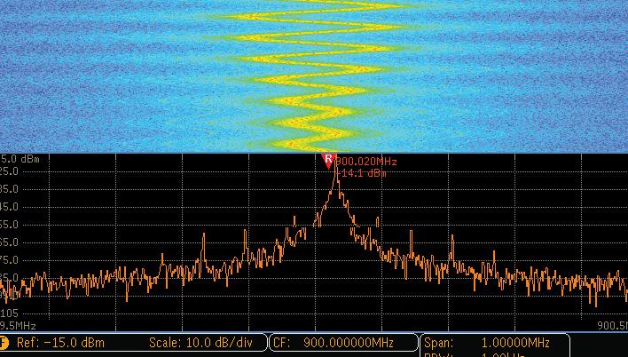
36 6. Press RF front panel button to turn on the RF channel. 7. Press Freq/Span front-panel button under the spectrum analyzer controls. 8. Use Multipurpose a or the 10-digit keypad to set the center frequency to 2.4 GHz. 9. Use Multipurpose b to set the span to 20 MHz. 10. Press menu off. Now you see multiple peaks with markers automatically marking the frequency and amplitude. The highest amplitude peak is the Reference Marker and is shown in red. Reference Marker to Center side-bezel button sets the Center Frequency to the frequency of the Reference Marker. 11. Press the Markers front panel button. You can set numbers of Peak Markers and Manual Marks using side-bezel buttons. Figure
37 B. Spectrogram Demonstration Spectrograms are useful for monitoring slowly changing RF events, and for identifying low amplitude signals that are too subtle for the eye to catch. This exercise demonstrates how the oscilloscope spectrogram shows what is happening in the spectrum over time, and shows how to look at the Spectrum Slices using the Multipurpose a control. 1. Follow step 1 to 3 in the previous exercise to connect the RF channel to the demonstration board. 2. Press the Mode button on the Demonstration board until the Spectrogram LED is lit. 3. Press Default setup front-panel button. 4. Press the RF front panel button to turn on RF channel. 5. Press the Freq/Span front-panel button. 6. Press the R to Center side-bezel button to set the Center Frequency to the frequency of the reference marker. 7. Use Multipurpose b to set span to 10 MHz. 8. Press the RF front panel button to turn on the RF menu. 9. Press the Spectrogram lower-bezel button. 10. Press the Display On side-bezel button to turn on the spectrogram. 37
38 11. Press the Run/Stop front panel button to stop acquiring. 12. Turn the Multipurpose a control to scroll through Spectrum Slices. A Spectrogram shows how the spectrum changes over time. The x-axis is frequency, the y-axis is time. A Spectrogram is created by taking each spectrum and flipping it up on its edge so that it s one pixel row tall and then using color to indicate amplitude. Hotter colors (red, yellow) indicate higher amplitudes while colder colors (blue, green) indicate lower amplitudes. Figure
39 Exercise 6 Generating Waveforms with the Integrated AFG Arbitrary function generators (AFG) are useful in a number of applications, including adding noise to signals to test noise immunity in a system, emulating missing components in a design, and sweeping frequencies or modulating signals for characterization in time/frequency domains. The MDO3000 Series oscilloscope with the 50 MHz integrated AFG can easily replicate signals acquired by the oscilloscope with added noise or other analog characteristics. The MDO3000 also works in conjunction with ArbExpress PC-based arbitrary waveform editing software to create even more complex waveforms that can be generated by the AFG in the oscilloscope. This exercise shows how you can capture a waveform on the oscilloscope, transfer it to the arbitrary function generator and replicate it. Note: You could purchase the MDO3AFG option to enable the AFG functionality. For demonstration purposes MDO3AFG option is enabled in MDO3000 demo units. 39

40 1. Connect a BNC cable to Channel 1 and to the AFG output on the rear of the oscilloscope. 2. Connect a passive probe to Channel 2 on the oscilloscope. 3. Connect the ground lead of the probe to the GND point and the probe tip to the RARE_ANOMALY signal on the demonstration board. 4. Press Default Setup front-panel button. 5. Press the Channel 1 front-panel button twice to turn off channel 1 and press the Channel 2 front-panel button to turn on channel Turn the Horizontal Scale knob to select 200 ns per division. 7. Press trigger Menu, select Type lowerbezel button, use Multipurpose a to scroll down to Runt. 8. Press Source 1 lower-bezel button and change the source to Channel 2. Figure
41 9. Press the Thresholds lower-bezel button and adjust High to approximately 2.00 V using Multipurpose a, adjust Low to about 1.00 V using Multipurpose b. 10. Press the Mode lower-bezel button. Press the Normal side-bezel button. 11. Press Single to take one acquisition. 12. Press the AFG front panel button to open the AFG menu. 13. Under Waveform Sine lower-bezel button, use Multipurpose a to select Arbitrary. 14. Press the Waveform Edit lower-bezel button. 15. Press the Load Waveform lower-bezel button. 16. Press the OK Load button to copy the acquired waveform on Channel 2 into the arbitrary edit memory. Figure
42 17. Press the Channel 2 front panel button twice to turn off channel 2 and press the Channel 1 front panel button to turn on channel Press the Run/Stop front panel button to start acquiring the output of the AFG. 19. Turn the front-panel channel 1 Vertical Scale knob to set channel 1 to 1.00 V per div. 20. Press the Trigger Menu front panel button. 21. Press the Source lower-bezel button and change the source to Channel Press the Thresholds lower-bezel button and adjust High to approximately 2.00 V using Multipurpose a, adjust Low to about 1.00 V using Multipurpose b. Now you are triggered on the runt signal generated by MDO3000 integrated AFG. Figure
43 Exercise 7 Measuring Signals with the Integrated DVM The integrated digital voltmeter (DVM) is free when you register your MDO3000. It monitors voltage values of critical signals or power rails in your system at a glance without having to connect a separate meter. The oscilloscope offers 3.5-digit Voltage Measurements for AC+DC RMS, AC RMS, and DC and 5.5-digit a Frequency Measurement through the same probes as the oscilloscope channels. This functionality is decoupled from the scope trigger circuit allowing for uninterrupted measurements that are always available, even when the scope is not running. This exercise shows how you can measure DC voltage on a signal over time. 1. Connect a BNC cable to Channel 1 and to the AFG output on the rear of the oscilloscope. 2. Press Default setup front-panel button. 3. Press the AFG front panel button to bring up the AFG menu. 4. Select the Waveform Settings lower-bezel button to change the Amplitude and Offset of the sine waveform. 5. Use the key pad (or Multipurpose a and b) and side-bezel buttons to set the AFG with a Sine wave at 100 khz frequency, 1Vp-p amplitude, and 500mV offset. 43

44 6. Set horizontal scale to 10μs/div. 7. Set Ch1 vertical scale to 200mV/div and use vertical position to center the waveform. 8. Press the Trigger Level control to set the trigger level to 50% of Ch1. Figure

45 9. Press the Measure front panel button. 10. Press the DVM lower-bezel button to turn on the DVM. 11. Use Multipurpose a to choose DC on Full display. 12. Press Menu Off to remove all menus. Figure
46 Locating Signals on Demo Board The following diagram includes a grid to help you locate signal outputs. To find a particular signal output on the board, look up the connector grid location in the following Signal Descriptions section and use the grid location information to find the signal on the demo board. Figure
47 DAC Input, Parallel Board label: DAC_IN0, DAC_IN1, DAC_IN2, DAC_IN3, DAC_IN4, DAC_IN5, DAC_IN6, DAC_IN7 Grid location: H3, H4 Description: These signals are the input to the DAC. These are also the 8-bit parallel output signals of the port expander in the middle of the mixed signal chain. The sine wave data from the SPI bus is converted to 8 parallel bits to drive the DAC. DAC_IN0 is the LSB. (See Figure 35.) Figure 35. Mixed signal chain block diagram. DAC Output Board label: DAC_OUT Grid location: H3 Description: This is the output of the DAC at the end of the mixed signal chain. The DAC is driven from the port expander. The DAC output is a sine wave. Since the output is not filtered, the digitizing levels are present in the output waveform. (See Figure 35.) The resulting DAC voltage is a sine wave with an amplitude of 0 to 3 volts, and a period of 31 ms. 47
48 Frequent Anomaly Board label: FREQ_ANOMALY Grid location: A9 Description: There are two frequently occurring anomalies in this pulse train. A half height runt signal occurs approximately every ms. Use a Runt trigger to isolate the signal. A 25 ns (narrow) pulse appears approximately every ms. Use a Pulse Width trigger to isolate the signal. The pulse train is a repeating group of three pulses. The three pulses are 100 ns, 200 ns, and 100 ns wide, with a 100 ns low between. The group repeats at a 1.6 μs rate. The anomaly is a group of four pulses. The four pulses are 100 ns, 50 ns (narrow), 100 ns (runt), and 100 ns wide, with a 100 ns low between, except for a 50 ns low before the runt. I 2 C Bus Board label: I2C_CLK, I2C_DATA Grid location: H2, H3 Description: These are the I2C (Inter-IC Communication) bus signals between the μc and a serial EEPROM. There are several different types of data packets. The clock rate is a 200 khz, 0 to 5 volt signal. Mode Button Board label: Mode Grid location: A11 Description: Press this button to choose which of the seven alternative signals to send out of the RF output connector. Your current choice is identified by which of the seven related red LEDs is lighted. Multiple Peaks Demo The RF output connector generates an array of frequencies, which are centered around 2.4 GHz, to show the ability of the MDO3000 Series oscilloscopes to dynamically mark each peak in the frequency domain with its exact frequency and amplitude. The red LED labeled Multiple Peaks at grid location B11 turns on. Spectrogram Demo The RF output connector generates an array of frequencies, which are centered around 2.4 GHz and are both amplitude and frequency modulated, to show the value of the Spectrogram function on slowly changing RF phenomena. The red LED labeled Spectrogram at grid location B11 turns on. 48
49 Rare Anomaly Board label: RARE_ANOM Grid location: A10 Description: The two less-frequent anomalies in this pulse train can show up on high waveform capture rate oscilloscopes. A half-height runt signal occurs approximately every ms. Use a Runt trigger to isolate the signal. A 25 ns (narrow) pulse appears in approximately ms. Use a Pulse Width trigger to isolate the signal. The pulse train is a repeating group of three pulses. The three pulses are 100 ns, 200 ns, and 100 ns wide, with a 100 ns low between each pulse. The group repeats at a 1.6 μs rate. The anomaly is a group of four pulses. The four pulses are 50 ns, 25 ns (narrow), 100 ns (runt), and 100 ns wide, with a 100 ns low between each pulse, except for a 25 ns low before the narrow pulse. Reset Button Board label: RESET Grid location: B7 Description: Press this button to start all generated signals from a common point. RF Output Board label: None Grid location: H9 Description: Use the RF output from this connector in the seven different RF demos controlled by the Mode button. Directly connect this output to the RF input of the MDO3000 Series oscilloscope. 49
50 Contact Tektronix: North America 1 (800) Worldwide visit: to find contacts in your area. Copyright 2013, Tektronix. All rights reserved. Tektronix products are covered by U.S. and foreign patents, issued and pending. Information in this publication supersedes that in all previously published material. Specification and price change privileges reserved. TEKTRONIX and TEK are registered trademarks of Tektronix, Inc. All other trade names referenced are the service marks, trademarks or registered trademarks of their respective companies. 12/13 EA/WWW 48W
Digital Debug With Oscilloscopes Lab Experiment
 Digital Debug With Oscilloscopes A collection of lab exercises to introduce you to digital debugging techniques with a digital oscilloscope. Revision 1.0 Page 1 of 23 Revision 1.0 Page 2 of 23 Copyright
Introduction to Oscilloscopes Instructor s Guide
 Introduction to Oscilloscopes A collection of lab exercises to introduce you to the basic controls of a digital oscilloscope in order to make common electronic measurements. Revision 1.0 Page 1 of 25 Copyright
MDO3000 Series Mixed Domain Oscilloscopes
 xx MDO3000 Series Mixed Domain Oscilloscopes ZZZ User Manual www.tektronix.com 077-0968-00 Get Acquainted with the Instrument Front Panel Menus and Controls The front panel has buttons and controls for
Wave Inspector Navigation and Search: Simplifying Waveform Analysis
 Wave Inspector Navigation and Search: Simplifying Waveform Analysis Our thanks to Tektronix for allowing us to reprint the following article. Introduction As Moore s Law pushes electronic technology faster,
Mixed Domain Oscilloscopes MDO3000 Series Datasheet
 Mixed Domain Oscilloscopes MDO3000 Series Datasheet Spectrum Analyzer Frequency range Standard: oscilloscope bandwidth Optional: 3 GHz Ultra-wide capture bandwidth up to 3 GHz Arbitrary Function Generator
Mixed Domain Oscilloscopes MDO3000 Series Datasheet
 Mixed Domain Oscilloscopes MDO3000 Series Datasheet Logic Analyzer (Optional) 16 digital channels 10 M record length on all channels 121.2 ps timing resolution Protocol Analyzer (Optional) Serial bus support
Mixed Domain Oscilloscopes MDO4000C Series Datasheet
 Mixed Domain Oscilloscopes MDO4000C Series Datasheet Customizable and fully upgradeable 6-in-1 integrated oscilloscope with synchronized insights into analog, digital, and RF signals Introducing the world's
Mixed Domain Oscilloscopes MDO4000C Series Datasheet
 Test Equipment Depot - 800.517.8431-99 Washington Street Melrose, MA 02176 - TestEquipmentDepot.com Mixed Domain Oscilloscopes MDO4000C Series Datasheet Customizable and fully upgradeable 6-in-1 integrated
Mixed Domain Oscilloscopes MDO3000 Series Datasheet
 Mixed Domain Oscilloscopes MDO3000 Series Datasheet Key performance specifications The ultimate 6-in-1 integrated oscilloscope, completely customizable and fully upgradeable Today's integrated designs
Mixed Domain Oscilloscopes MDO4000C Series Datasheet
 Mixed Domain Oscilloscopes MDO4000C Series Datasheet WINNER OF 13 INDUSTRY AWARDS Customizable and fully upgradable 6-in-1 integrated oscilloscope with synchronized insights into analog, digital, and RF
Mixed Domain Oscilloscopes
 Test Equipment Depot - 800.517.8431-99 Washington Street Melrose, MA 02176 - TestEquipmentDepot.com Mixed Domain Oscilloscopes MDO3000 Series Datasheet INDUSTRY AWARDS 2. Spectrum Analyzer Frequency range
MDO4000B Series Mixed Domain Oscilloscope. Product Selection and Comparison Guide
 MDO4000B Series Mixed Domain Oscilloscope Product Selection and Comparison Guide Table of Contents About this Guide...3 Key Highlights You ll Find in this Guide...3 Oscilloscope Guide...4 Oscilloscope
Page 1/10 Digilent Analog Discovery (DAD) Tutorial 6-Aug-15. Figure 2: DAD pin configuration
 Tutorial 6-Aug-15. Figure 2: DAD pin configuration") Page 1/10 Digilent Analog Discovery (DAD) Tutorial 6-Aug-15 INTRODUCTION The Diligent Analog Discovery (DAD) allows you to design and test both analog and digital circuits. It can produce, measure and
Page 1/10 Digilent Analog Discovery (DAD) Tutorial 6-Aug-15 INTRODUCTION The Diligent Analog Discovery (DAD) allows you to design and test both analog and digital circuits. It can produce, measure and
Reference. TDS6000 Series Digital Storage Oscilloscopes
 Reference TDS6000 Series Digital Storage Oscilloscopes 07-703-0 077030 To Use the Front Panel You can use the dedicated, front-panel knobs and buttons to do the most commonly performed operations. Turn
Combinational logic: Breadboard adders
 ! ENEE 245: Digital Circuits & Systems Lab Lab 1 Combinational logic: Breadboard adders ENEE 245: Digital Circuits and Systems Laboratory Lab 1 Objectives The objectives of this laboratory are the following:
Visual Triggering. Technical Brief
 Visual Triggering Technical Brief Capturing and finding the right characteristic of a complex signal can require hours of collecting and sorting through thousands of acquisitions for the event of interest.
LAB I. INTRODUCTION TO LAB EQUIPMENT
 1. OBJECTIVE LAB I. INTRODUCTION TO LAB EQUIPMENT In this lab you will learn how to properly operate the oscilloscope Agilent MSO6032A, the Keithley Source Measure Unit (SMU) 2430, the function generator
Getting Started. MSO/DPO Series Oscilloscopes. Basic Concepts
 Getting Started MSO/DPO Series Oscilloscopes Basic Concepts 001-1523-00 Getting Started 1.1 Getting Started What is an oscilloscope? An oscilloscope is a device that draws a graph of an electrical signal.
RIGOL. User s Guide. DS6000 Digital Oscilloscope Demo Board. July RIGOL Technologies, Inc.
 RIGOL User s Guide DS6000 Digital Oscilloscope Demo Board July 2011 RIGOL Technologies, Inc. RIGOL Guaranty and Declaration Copyright 2011 RIGOL Technologies, Inc. All Rights Reserved. Trademark Information
UNIVERSITY OF CALIFORNIA, SANTA BARBARA Department of Electrical and Computer Engineering. ECE 2A & 2B Laboratory Equipment Information
 UNIVERSITY OF CALIFORNIA, SANTA BARBARA Department of Electrical and Computer Engineering ECE 2A & 2B Laboratory Equipment Information Table of Contents Digital Multi-Meter (DMM)... 1 Features... 1 Using
WaveAce 1000 and 2000 Oscilloscopes
 1000 and 2000 Oscilloscopes 40 MHz 300 MHz Key Features Sample rates up to 2 GS/s 1 Mpts/ch memory, 2 Mpts interleaved 7" color display on all models 32 automatic measurements Multi-language user interface
Introduction to Lab Instruments
 ECE316, Experiment 00, 2017 Communications Lab, University of Toronto Introduction to Lab Instruments Bruno Korst - bkf@comm.utoronto.ca Abstract This experiment will review the use of three lab instruments
P a g e 1 ST985. TDR Cable Analyzer Instruction Manual. Analog Arts Inc.
 P a g e 1 ST985 TDR Cable Analyzer Instruction Manual Analog Arts Inc. www.analogarts.com P a g e 2 Contents Software Installation... 4 Specifications... 4 Handling Precautions... 4 Operation Instruction...
MSO Supplied with a full SDK including example programs Software compatible with Windows XP, Windows Vista and Windows 7 Free Technical Support
 PicoScope 2205 MSO USB-POWERED MIXED SIGNAL OSCILLOSCOPE Think logically... 25 MHz analog bandwidth 100 MHz max. digital input frequency 200 MS/s mixed signal sampling Advanced digital triggers SDK and
54645D. Mixed Signal Oscilloscope
 54645D Mixed Signal Oscilloscope Page 1 of 42 Instructions for the use of the 54645D Mixed Signal Oscilloscope This pamphlet is intended to give you (the student) an overview on the use of the 54645D Mixed
Wave Inspector Navigation and Search: Simplifying Waveform Analysis. Introduction. Application Note
 Wave Inspector Navigation and Search: Simplifying Waveform Analysis Introduction As Moore s Law pushes electronic technology faster, system designs continue to become more complex, and subsequently harder
The Oscilloscope. Vision is the art of seeing things invisible. J. Swift ( ) OBJECTIVE To learn to operate a digital oscilloscope.
 OBJECTIVE To learn to operate a digital oscilloscope.") The Oscilloscope Vision is the art of seeing things invisible. J. Swift (1667-1745) OBJECTIVE To learn to operate a digital oscilloscope. THEORY The oscilloscope, or scope for short, is a device for drawing
The Oscilloscope Vision is the art of seeing things invisible. J. Swift (1667-1745) OBJECTIVE To learn to operate a digital oscilloscope. THEORY The oscilloscope, or scope for short, is a device for drawing
UCE-DSO210 DIGITAL OSCILLOSCOPE USER MANUAL. FATIH GENÇ UCORE ELECTRONICS REV1
 UCE-DSO210 DIGITAL OSCILLOSCOPE USER MANUAL FATIH GENÇ UCORE ELECTRONICS www.ucore-electronics.com 2017 - REV1 Contents 1. Introduction... 2 2. Turn on or turn off... 3 3. Oscilloscope Mode... 3 3.1. Display
Getting the most out of your Measurements Workshop. Mike Schnecker
 Getting the most out of your Measurements Workshop Mike Schnecker Agenda Oscilloscope Basics Using a RTE1000 Series Oscilloscope. Probing Basics Passive probe compensation Ground lead effects Vertical
10 FACTORS IN CHOOSING A BASIC OSCILLOSCOPE
 10 FACTORS IN CHOOSING A BASIC OSCILLOSCOPE 2 10 Factors in Choosing a Basic Oscilloscope There are several ways to navigate this interactive PDF document: Basic oscilloscopes are used as windows into
Replicating Real World Signals with an Arbitrary/Function Generator
 Replicating Real World Signals with an Arbitrary/Function Generator Application Note Introduction Nearly all consumer products today have circuits or devices that require the input of specific electronic
DLM3022, DLM3032, DLM3052
 DLM3022, DLM3032, DLM3052 Digital Oscilloscope DLM3024, DLM3034, DLM3054 Mixed Signal Oscilloscope Features Guide 1st Edition Thank you for purchasing the DLM3022, DLM3032, or DLM3052 digital oscilloscope
EENG-201 Experiment # 4: Function Generator, Oscilloscope
 EENG-201 Experiment # 4: Function Generator, Oscilloscope I. Objectives Upon completion of this experiment, the student should be able to 1. To become familiar with the use of a function generator. 2.
Notes on Experiment #1
 Notes on Experiment #1 Bring graph paper (cm cm is best) From this week on, be sure to print a copy of each experiment and bring it with you to lab. There will not be any experiment copies available in
HP 16533A 1-GSa/s and HP 16534A 2-GSa/s Digitizing Oscilloscope
 User s Reference Publication Number 16534-97009 February 1999 For Safety Information, Warranties, and Regulatory Information, see the pages behind the Index Copyright Hewlett-Packard Company 1991 1999
How to Troubleshoot System Problems Using an Oscilloscope with I 2 C and SPI Decoding
 How to Troubleshoot System Problems Using an Oscilloscope with I 2 C and SPI Decoding Introduction Most microcontroller-based designs use I 2 C or SPI or both, to communicate among controllers and between
Output Impedance. Duty Cycle Range. Buffer Size Resolution. PROTECTION Input Over Voltage. Output Short Circuit. TRIGGERING Sources.
 3 Channel Digital Storage Oscilloscope (DSO) Instrument VERTICAL SPECIFICATIONS Analogue Bandwidth (-3dB) Bandwidth Limiting Rise time (10% to 90%, calculated) Input ranges (full scale) Input sensitivity
MDO3000 Series Mixed Domain Oscilloscopes Specifications and Performance Verification
 x MDO3000 Series Mixed Domain Oscilloscopes Specifications and Performance Verification ZZZ Technical Reference *P077097900* 077-0979-00 xx MDO3000 Series Mixed Domain Oscilloscopes Specifications and
Laboratory Equipment Instruction Manual 2011
 University of Toronto Department of Electrical and Computer Engineering Instrumentation Laboratory GB341 Laboratory Equipment Instruction Manual 2011 Page 1. Wires and Cables A-2 2. Protoboard A-3 3. DC
Appendix A: Specifications
 All specifications apply to the TDS 200-Series Digital Oscilloscopes and a P2100 probe with the Attenuation switch set to 10X unless noted otherwise. To meet specifications, two conditions must first be
MSO-5000B Mixed Storage Oscilloscope User Manual
 MSO-5000B Mixed Storage Oscilloscope User Manual Contents Contents CONTENTS... I COPYRIGHT DECLARATION... IV CHAPTER 1 SAFETY TIPS... 1 1.1 GENERAL SAFETY SUMMARY... 1 1.2 SAFETY TERMS AND SYMBOLS... 2
DLM2000 Series. Digital Oscilloscope Mixed Signal Oscilloscope. Features Guide. IM E 8th Edition
 DLM2000 Series Digital Oscilloscope Mixed Signal Oscilloscope Features Guide 8th Edition Thank you for purchasing the DLM2000 Series Digital Oscilloscope/Mixed Signal Oscilloscope. This manual contains
Agilent N2740A Education Training Kit for 1000 Series Oscilloscopes
 Agilent N2740A Education Training Kit for 1000 Series Oscilloscopes Lab Manual A Notices Agilent Technologies, Inc. 2008 No part of this manual may be reproduced in any form or by any means (including
Supplement. TDS5032 and TDS5034 Digital Phosphor Oscilloscopes
 TDS5032 and TDS5034 Digital Phosphor Oscilloscopes 071-1316-00 www.tektronix.com 071131600 Copyright Tektronix, Inc. All rights reserved. Tektronix products are covered by U.S. and foreign patents, issued
Introduction to Basic Laboratory Instruments
 Introduction to Contents: 1. Objectives... 2 2. Laboratory Safety... 2 3.... 2 4. Using a DC Power Supply... 2 5. Using a Function Generator... 3 5.1 Turn on the Instrument... 3 5.2 Setting Signal Type...
UCE-DSO212 DIGITAL OSCILLOSCOPE USER MANUAL. UCORE ELECTRONICS
 UCE-DSO212 DIGITAL OSCILLOSCOPE USER MANUAL UCORE ELECTRONICS www.ucore-electronics.com 2017 Contents 1. Introduction... 2 2. Turn on or turn off... 3 3. Oscilloscope Mode... 4 3.1. Display Description...
N acquisitions, all channels simultaneously, N is selectable from 4, 16, 64, and 128 Inputs
 With compliments All specifications apply to the TDS 200-Series Digital Real-Time Oscilloscope with a P2100 probe with the Attenuation switch set to 10X unless noted otherwise. To meet specifications,
DSO5000P Series Digital Storage Oscilloscope User Manual. (Version 1.1)
") DSO5000P Series Digital Storage Oscilloscope User Manual (Version 1.1) Contents Contents Contents... i Chapter 1 Safety Tips... 1 1.1 General Safety Summary... 1 1.2 Safety Terms and Symbols... 2 1.3 Terms
DSO5000P Series Digital Storage Oscilloscope User Manual (Version 1.1) Contents Contents Contents... i Chapter 1 Safety Tips... 1 1.1 General Safety Summary... 1 1.2 Safety Terms and Symbols... 2 1.3 Terms
LAB I. INTRODUCTION TO LAB EQUIPMENT
 LAB I. INTRODUCTION TO LAB EQUIPMENT 1. OBJECTIVE In this lab you will learn how to properly operate the basic bench equipment used for characterizing active devices: 1. Oscilloscope (Keysight DSOX 1102A),
Agilent Technologies 3000 Series Oscilloscopes
 Agilent Technologies 3000 Series Oscilloscopes Data Sheet Full-featured oscilloscopes for the smallest budgets Features: 60 to 200 MHz bandwidths 1 GSa/s maximum sample rate Large 15-cm (5.7-in) color
DL9500/DL9700 Series. Digital Oscilloscope. IM E 3rd Edition
 DL9500/DL9700 Series Digital Oscilloscope 3rd Edition Thank you for purchasing the DL9500/DL9700 Series Digital Oscilloscope (DL9505L/DL950L/DL9705L/DL970L, hereafter referred to as the DL9500/DL9700).
Lab #1 Lab Introduction
 Cir cuit s 212 Lab Lab #1 Lab Introduction Special Information for this Lab s Report Because this is a one-week lab, please hand in your lab report for this lab at the beginning of next week s lab. The
LAB II. INTRODUCTION TO LAB EQUIPMENT
 1. OBJECTIVE LAB II. INTRODUCTION TO LAB EQUIPMENT In this lab you will learn how to properly operate the oscilloscope Keysight DSOX1102A, the Keithley Source Measure Unit (SMU) 2430, the function generator
Introduction to basic laboratory instruments
 BEE 233 Laboratory-1 Introduction to basic laboratory instruments 1. Objectives To learn safety procedures in the laboratory. To learn how to use basic laboratory instruments: power supply, function generator,
TLA5000 Golden Demo for Hardware Engineers
 Overview Introduction Who Should Use this Demo? Anyone that needs to demo the capabilities of the TLA5000 and has access to a TLA5000 and the TLA5000 demo board. Target Audience for Demo: Demo Details
Analog Arts SF990 SF880 SF830 Product Specifications
 1 www.analogarts.com Analog Arts SF990 SF880 SF830 Product Specifications Analog Arts reserves the right to change, modify, add or delete portions of any one of its specifications at any time, without
Troubleshooting Common EMI Problems
 By William D. Kimmel, PE Kimmel Gerke Associates, Ltd. Learn best practices for troubleshooting common EMI problems in today's digital designs. Industry expert William Kimmel of Kimmel Gerke Associates
DSO1000E/F Series Digital Storage Oscilloscope User Manual. (Version 1.3)
") DSO1000E/F Series Digital Storage Oscilloscope User Manual (Version 1.3) Copyright Declaration All rights reserved; no part of this document may be reproduced or transmitted in any form or by any means,
DSO1000E/F Series Digital Storage Oscilloscope User Manual (Version 1.3) Copyright Declaration All rights reserved; no part of this document may be reproduced or transmitted in any form or by any means,
Agilent 33522A Function Arbitrary Waveform Generator. Tektronix TDS 3012B Oscilloscope
 Agilent 33522A Function/Arbitrary Waveform Generator and Tektronix TDS 3012B Oscilloscope Agilent 33522A Function Arbitrary Waveform Generator The signal source for this lab is the Agilent 33522A Function
U1604A Handheld Oscilloscopes, 40 MHz
 Products & Services Technical Support Buy Industries About Agilent Search: All Test & Measurement Go United States Home >... > Oscilloscopes > U1600A Series handheld oscilloscopes (2 models) > U1604A Handheld
GDS-2000A 300/200/100/70 MHz DSO New Product Announcement
 GDS-2000A 300/200/100/70 MHz DSO New Product Announcement The GDS-2000A Series Digital Storage Oscilloscope offers 2 and 4-channel configurations and wide bandwidth selections, including 300MHz, 200MHz,
Faculty of Engineering, Thammasat University
 Faculty of Engineering, Thammasat University Experiment 6: Oscilloscope (For room 506) Objectives: 1. To familiarize you with the Oscilloscope and Function Generator User Manual: Oscilloscope 1 5 9 4 7
Function Generator Guide Tektronix AFG3102
 Tektronix AFG3102 ersion 2008-Jan-1 Dept. of Electrical & Computer Engineering Portland State University Copyright 2008 Portland State University 1 Basic Information This guide provides basic instructions
Be Sure to Capture the Complete Picture
 Be Sure to Capture the Complete Picture Technical Brief Tektronix Digital Real-time (DRT) Sampling Technology As an engineer or technician, you need the confidence and trust that you re accurately capturing
Agilent Technologies 3000 Series Oscilloscopes
 Agilent Technologies 3000 Series Oscilloscopes Data Sheet The performance and features you need at the industry s lowest price Features: 60 to 200 MHz bandwidths 1 GSa/s maximum sample rate Large 15-cm
LABORATORY 4. Palomar College ENGR210 Spring 2017 ASSIGNED: 3/21/17
 LABORATORY 4 ASSIGNED: 3/21/17 OBJECTIVE: The purpose of this lab is to evaluate the transient and steady-state circuit response of first order and second order circuits. MINIMUM EQUIPMENT LIST: You will
U1571A Ni-MH Battery Pack for U1600A Handheld Oscilloscopes
 United States Home >... > Oscilloscope Accessories > U1600 Series Oscilloscope Accessories > U1571A Ni-MH Battery Pack for U1600A Handheld Oscilloscopes Key Specifications Features Ni-MH Battery Pack,
Data Sheet. Digital Storage Oscilloscope. Features & Benefits. Applications. Ease-of-Use Feature DSO5202BMT DSO5102BMT DSO5062BMT
 Data Sheet Digital Storage Oscilloscope DSO5202BMT DSO5102BMT DSO5062BMT Features & Benefits 200/100/60MHz Bandwidths 1GSa/s Real Time Sample Rate 2M Memory Depth Trigger mode: Edge, Pulse Width, Video,
Testing with Versatile Pulse Generation Solutions
 Testing with Versatile Pulse Generation Solutions Introduction During the design of electronic components and circuits for computers, peripherals and serial communication, pulse pattern generators are
Analog Arts SL987 SL957 SL937 SL917 Product Specifications [1]
![Analog Arts SL987 SL957 SL937 SL917 Product Specifications [1]](/thumbs/95/126095980.jpg "Analog Arts SL987 SL957 SL937 SL917 Product Specifications [1]") www.analogarts.com Analog Arts SL987 SL957 SL937 SL917 Product Specifications [1] 1. These models include: an oscilloscope, a spectrum analyzer, a data recorder, a frequency & phase meter, an arbitrary
www.analogarts.com Analog Arts SL987 SL957 SL937 SL917 Product Specifications [1] 1. These models include: an oscilloscope, a spectrum analyzer, a data recorder, a frequency & phase meter, an arbitrary
MSO Supplied with a full SDK including example programs Software compatible with Windows XP, Windows Vista and Windows 7 Free Technical Support
 PicoScope 2205 MSO USB-POWERED MIXED SIGNAL OSCILLOSCOPE Think logically... 25 MHz analog bandwidth 100 MHz max. digital input frequency 200 MS/s mixed signal sampling Advanced digital triggers SDK and
6 Series MSO Mixed Signal Oscilloscope Datasheet
 6 Series MSO Mixed Signal Oscilloscope Datasheet www.tek.com/6seriesmso 1 Datasheet Confidence in numbers Input channels 4 FlexChannel inputs Each FlexChannel provides: Bandwidth One analog signal that
DS1000B Series Digital Oscilloscopes
 Product Overview DS1000B series oscilloscopes are designed with four analog channels and 1 external trigger channel, which can capture multi-channel signal simultaneously and meet industrial needs. The
DST Series B Type Digital Storage Oscilloscope User Manual
 DST Series B Type Digital Storage Oscilloscope User Manual Contents Contents Contents... i Copyright Declaration... iv Chapter 1 Safety Tips... 1 1.1 General Safety Summary... 1 1.2 Safety Terms and Symbols...
Department of Electrical & Computer Engineering OSCILLOSCOPE GUIDE. Tektronix TDS2000 Series
 OSCILLOSCOPE Department of Electrical & Computer Engineering GUIDE Tektronix TDS2000 Series Contents 1 INTRODUCTION... 2 2 OSCILLOSCOPE OVERVIEW... 2 3 INSTRUMENT FRONT PANEL... 3 Power Switch... 3 USB
Wave Inspector Navigation and Search: Simplifying Waveform Analysis APPLICATION NOTE
 Wave Inspector Navigation and Search: Simplifying Waveform Analysis APPLICATION NOTE Application Note Wave Inspector Controls Figure 1. Wave Inspector provides dedicated front-panel controls for efficient
Product Channels Bandwidth Sampling Rate Memory Resolution
 Nov@tek Oscilloscope and Spectrum Analyzer Introduction The 4-channel digital storage oscilloscope at an outstanding price! When connected to PC with USB2.0 interface, you get a fully-featured storage
5 Series MSO Mixed Signal Oscilloscope Datasheet
 5 Series MSO Mixed Signal Oscilloscope Datasheet www.tek.com/5seriesmso 1 Datasheet Strength in numbers Input channels 4, 6, or 8 FlexChannel inputs Each FlexChannel provides one analog signal input or
EXPERIMENT NUMBER 2 BASIC OSCILLOSCOPE OPERATIONS
 1 EXPERIMENT NUMBER 2 BASIC OSCILLOSCOPE OPERATIONS The oscilloscope is the most versatile and most important tool in this lab and is probably the best tool an electrical engineer uses. This outline guides
Name EET 1131 Lab #2 Oscilloscope and Multisim
 Name EET 1131 Lab #2 Oscilloscope and Multisim Section 1. Oscilloscope Introduction Equipment and Components Safety glasses Logic probe ETS-7000 Digital-Analog Training System Fluke 45 Digital Multimeter
Debugging SENT Automotive Buses with an Oscilloscope APPLICATION NOTE
 Debugging SENT Automotive Buses with an Oscilloscope Introduction Increasingly, automotive designs are adopting Single Edge Nibble Transmission (SENT) protocol for low-cost, asynchronous, point-topoint
EE 201 Lab! Tektronix 3021B function generator
 EE 201 Lab Tektronix 3021B function generator The function generator produces a time-varying voltage signal at its output terminal. The Tektronix 3021B is capable of producing several standard waveforms
ME 365 EXPERIMENT 1 FAMILIARIZATION WITH COMMONLY USED INSTRUMENTATION
 Objectives: ME 365 EXPERIMENT 1 FAMILIARIZATION WITH COMMONLY USED INSTRUMENTATION The primary goal of this laboratory is to study the operation and limitations of several commonly used pieces of instrumentation:
2 Oscilloscope Familiarization
 Lab 2 Oscilloscope Familiarization What You Need To Know: Voltages and currents in an electronic circuit as in a CD player, mobile phone or TV set vary in time. Throughout the course you will investigate
If I Could... Imagine Perfect Vision
 If I Could... Imagine Perfect Vision With the right oscilloscope you can create better designs, faster. You can characterize circuit performance with greater precision and confidence. You can verify system
LAB #7: Digital Signal Processing
 LAB #7: Digital Signal Processing Equipment: Pentium PC with NI PCI-MIO-16E-4 data-acquisition board NI BNC 2120 Accessory Box VirtualBench Instrument Library version 2.6 Function Generator (Tektronix
ArbStudio Training Guide
 ArbStudio Training Guide Summary This guide provides step by step instructions explaining how to create waveforms, use the waveform sequencer, modulate waveforms and generate digital patterns. The exercises
Sampling and Reconstruction
 Experiment 10 Sampling and Reconstruction In this experiment we shall learn how an analog signal can be sampled in the time domain and then how the same samples can be used to reconstruct the original
5 Series MSO Mixed Signal Oscilloscope Datasheet
 5 Series MSO Mixed Signal Oscilloscope Datasheet www.tek.com/5seriesmso 1 Datasheet Strength in numbers Input channels 4, 6, or 8 FlexChannel inputs Each FlexChannel provides one analog signal input or
Bench Products Catalog. 2014, Volume Bench Products. Test & Measurement Solutions
 Bench Products Catalog 2014, Volume 2 2014 Bench Products Test & Measurement Solutions 6 Instruments.1 Scope. Infinite Versatility. Digital Voltmeter Protocol Analyzer Logic Analyzer Arbitrary/Function
Analog Arts SF900 SF650 SF610 Product Specifications
 www.analogarts.com Analog Arts SF900 SF650 SF610 Product Specifications Analog Arts reserves the right to change, modify, add or delete portions of any one of its specifications at any time, without prior
2 : AC signals, the signal generator and the Oscilloscope
 2 : AC signals, the signal generator and the Oscilloscope Expected outcomes After conducting this practical, the student should be able to do the following Set up a signal generator to provide a specific
Bench Products Catalog. 2011, Volume Bench Products. Test & Measurement Solutions
 Bench Products Catalog 2011, Volume 5 2011 Bench Products Test & Measurement Solutions Table of Contents Table of Contents Table of Contents Product Highlight...3 Oscilloscopes... 4-7 Selection Guides...
Lab 0: Introduction to basic laboratory instruments. Revised by Dan Hoang & Tai-Chang Chen 03/30/2009
 Lab 0: Introduction to basic laboratory instruments Revised by Dan Hoang & Tai-Chang Chen 03/30/2009 1. Objectives 1. To learn safety procedures in the laboratory. 2. To learn how to use basic laboratory
LeCroy 9304A, 9304AM Digital Oscilloscopes 200 MHz Bandwidth, 100 MS/s. Main Features
 LeCroy 9304A, 9304AM Digital Oscilloscopes 200 MHz Bandwidth, 100 MS/s Main Features Four Channels 50k and 200k Point Records DOS Compatible Floppy Disk, PCMCIA portable hard drive and Memory Card Options
Agilent Technologies 3000 Series Oscilloscopes
 Agilent Technologies 3000 Series Oscilloscopes Data Sheet Full-featured oscilloscopes for the smallest budgets Features: 60 to 200 MHz bandwidths 1 GSa/s maximum sample rate Large 15-cm (5.7-in) color
DSO4000BC Series Digital Storage Oscilloscope User Manual
 DSO4000BC Series Digital Storage Oscilloscope User Manual (V1.3) Copyright Declaration All rights reserved; no part of this document may be reproduced or transmitted in any form or by any means, electronic
Laboratory equipments. Parameters of digital signals.
 Laboratory 1 Laboratory equipments. Parameters of digital signals. 1.1 Objectives This laboratory presents detailed description of the equipments used during the lab and measurement techniques specifically
1.0 Introduction to VirtualBench
 Table of Contents 1.0 Introduction to VirtualBench... 3 1. 1 VirtualBench in the Laboratory... 3 1.2 VirtualBench Specifications... 4 1.3 Introduction to VirtualBench Getting Started Guide Lab Exercises...
Product Catalog. For more information, please contact:
 Product Catalog For more information, please contact: HDO4000 OSCILLOSCOPES Debug in High Definition 200 MHz 1 GHz Combining Teledyne LeCroy s HD4096 high definition technology, with long memory, a compact