Introduction to Measurement Techniques
|
|
|
- Lilian Nichols
- 5 years ago
- Views:
Transcription


1 Introduction to Measurement Techniques Andrés García Aguilar Outline 1. Introduction, 2. Far-field ranges, 3. Anechoic chambers, 4. Near-field systems: Spherical, planar & cylindrical, 5. Compact ranges, 6. Polarization measurements, 7. Measurement instrumentation, 8. Power and dynamic range, 9. Gain standards and Gain measurements, 10. Other measurement systems. 2
2 It Introduction ti 3 Introduction Definition of an antenna by the Webster ss Dictionary: a usually metallic device for radiating or receiving radio waves. Definition of an antenna by IEEE Standard Definitions of Terms for Antenna: a mean for radiating or receiving radio waves i.e. antenna is the transitional structure between free-space and a guiding device. Aims of Antenna Measurements: Evaluation of designed antennas, Empirical validation for antenna analysis methods. Antenna Parameters to be measured: Radiation pattern parameters: directivity, cross-polar radiation... Gain and antenna efficiency, Impedance and port isolations. Antenna measurement systems according to field regions: Outdoor far field ranges, Anechoic chambers: planar, cylindrical, spherical near-field systems, compact ranges 4
3 Field Regions Space surrounding S di an antenna is i subdivided bdi id d in: i Reactive near field region: that portion of the near field region g immediately y surrounding g the antenna, where the reactive field predominates. Radiating near field region: (Includes Fresnel zone): ) intermediate region, region where here the radiation fields predominate, but the angular field distribution depends upon the distance from the antenna. t Far Field (Fraunhofer) region: the region of the field of an antenna where the angular g field distribution is independent of the distance from the antenna. Far field distance satisfies: 2 D2 y r D: Maximum dimension of the antenna r 5 Example: radiated field of an antenna Simulated Vertical radiation pattern for a 9 resonant dipoles (h=210 cm) at 900 MHz MHz. Far field distance = 26.7 m: distance d: a) d = 27 m b) d = 13.5 m c) d = 6.75 m d) d = 2.7 m a) db db d) db c) b) db
4 Antennas and far-field distances For monopoles and dipoles (length λ), R far field 10λ is used, because reactive field is negligible. For large reflectors in microwave band with circular aperture with D >> λ, R far field 2D 2 /λ is used, because of the phase errors at the aperture. For base station antennas (arrays with height h >> λ), R far field 2h 2 /λ is used, because of the phase errors at the aperture. 7 Antenna Measurement Systems Compact Systems Far-Field Systems: Elevated & Ground Reflection Ranges Near-Field Systems: Planar, Cylindrical i l & Spherical 8
5 Far-field ranges 9 Far field ranges Antenna under test (AUT), usually in reception, is illuminated by a source (probe antenna). This antenna must be in far field distance. In this case, the incident wave is a plane wave. Source antenna AUT TheAUTcanbemeasuredin transmission or in reception. Radiation patterns and parameters are the same, according to the reciprocity theorem. 10
 covered by")

.")

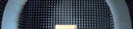
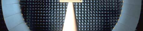
6 Anechoic chambers 11 Anechoic chambers Close areas (normally shielded) covered by electromagnetic absorbing material, that simulate free space propagation conditions, due to the absorption of the radiation absorbing material (RAM). Advantages: All weather operation. Control of the environment (temperature, cleanness...) Security. Freedom from interference. 12
: < -50 db. Convoluted absorbers: < -50 db in mm-wavelengths.")
.")
 Rectangular Test chamber: max <70º")

 Tapered Test Chamber: W Interference signals eliminate the ripple in")
7 Anechoic chambers: Microwave Absorbing materials Pyramidal absorbers (H>5): < -50 db. Convoluted absorbers: < -50 db in mm-wavelengths. Flat laminate absorbers: < -25 db (towers...). Wlk Walkway absorbers: b (pyramidal + foam + polystyrene laminate). Wedge absorbers: for compact ranges. All weather or vent absorbers. 13 Anechoic chambers: Examples a) Rectangular Test chamber: max <70º W/R>1/ R Source antenna main lobe can t illuminate the side walls, floor or ceiling. b) Tapered Test Chamber: W Interference signals eliminate the ripple in quiet zone. Used in VHF and UHF. The source is adjusted at each frequency. c) Semi-open chamber: AUT is protected by a building (without one wall). The antenna source is far away. 14
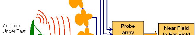
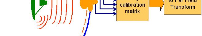
8 Near-field systems: Spherical, planar, cylindrical 15 Near field systems The radiated field is measured in a surface (plane, cylinder or sphere) near to the AUT, and the far field is obtained using a transformation algorithm. Advantages: Less use of space, Indoor systems advantages (independent of weather conditions ), The far field is obtained without the error due to the finite distance. Drawbacks: More complex and precise exploring systems are required, Transformation software based on modal analysis (with plane, cylindrical or spherical waves), A probe calibration is necessary. 16
9 Near field theory If we know the tangential component of the fields over a closed surface including all the sources, it is possible to know the fields wherever outside it. A.D. Yaghiang, An Overview of Near-Field Antenna Measurements, IEEE Transactions on Antennas And Propagation, Vol. AP-34. Nº 1, January Types of near-field scanning Planar System XY (Transformation: FFT) Cylindrical System Spherical lsystem 18
10 Planar near-field system: theoretical analysis In the planar near-field system, the coupling equation relates the measured values with the probe correction coefficients and the AUT transmission coefficients. Since they are related by a Fourier Transform,, it can be solved applying ppy an Inverse Fourier Transform. Ideal Probe situation (ideal dipole) A.D. Yaghiang, An Overview of Near-Field Antenna Measurements, IEEE Transactions on Antennas And Propagation, Vol. AP-34. Nº 1, January Planar near-field system: theoretical analysis Real Probe situation Far-Field A.D. Yaghiang, An Overview of Near-Field Antenna Measurements, IEEE Transactions on Antennas And Propagation, Vol. AP-34. Nº 1, January
11 Planar near-field system: practical aspects Angular validity of the measurement: Measurement tplane Sampling acquisitions has to be limited to a finite rectangle in the measurement plane. This truncation limits the validity of measurement result in far field to angles lower to θ v. v L x D v atan 2z0 ABP z 0 If E(L x /2) < -40 db, the truncation error is negligible. ibl Maximum sampling rate Sampling Theorem D Lx 2 x 2k 2 y 2 (In some conditions, it can be higher) 21 Planar near-field system 22
12 UPM antenna measurement ranges Planar System: Dimensions: 6 meters lower horizontal guide 1 meter supporting cart 5.5 meters tower upper horizontal guide at 2 meters - 3 high precision linear elements assure the scanner high precision. - The lower horizontal guide is a linear ball spline, that allows a free rotation of the vertical tower. - The tower leans on the upper horizontal guide. - Scan area: 4.75 x 4.75 meters - Frequency band: GHz - Horizontal axis velocity: 10 cm/sec - Vertical axis velocity: 33 cm/sec - z errors < 0,34mm peak to peak in the scan area 23 Cylindrical near-field system In the cylindrical near-field system, the coupling equation relates the measured values with the probe correction coefficients and the AUT transmission coefficients. With 2 set of measured values for each polarization & the probe correction coefficients, the AUT transmission coefficients could be derived. Then, with these AUT transmission coefficients, the θ-components & φ-components of the far-field field can be obtained. 24
13 Cylindrical near-field system: theoretical analysis Ideal Probe situation Real Probe situation Far-Field A.D. Yaghiang, An Overview of Near-Field Antenna Measurements, IEEE Tansactions on Antennas And Propagation, Vol. AP-34. Nº 1, January Cylindrical near-field system: practical aspects Angular validity of the measurement: Measurement tcylinder Sampling acquisitions has to be limited to a finite rectangle in the measurement plane. This truncation limits the validity of measurement result in far field to angles lower to θ v. v L x D v atan 2z0 ABP z 0 If E(L x /2) < -40 db, the truncation error is negligible. ibl Maximum sampling rate Sampling Theorem Vertical direction: the same than planar system, Horizontal direction: the same than the spherical system. D Lx 26


14 Cylindrical near-field system 27 UPM antenna measurement ranges Cylindrical and Spherical System: - Sharing elements with the planar system. - Cylindrical: AUT on Azimuth positioner and probe on scanner y-axis. - Spherical system: AUT on Roll over Azimuth - Frequency band: 1 40 GHz - Linear slide to adjust measurement distance. CYLINDRICAL SYSTEM 28


15 Spherical near-field system: theoretical analysis Ideal Probe situation Real Probe situation Far-Field A.D. Yaghiang, An Overview of Near-Field Antenna Measurements, IEEE Tansactions on Antennas And Propagation, Vol. AP-34. Nº 1, January Example of an spherical near-field system 30

 at")

16 UPM antenna measurement ranges Spherical System: Dimensions: 7.3 x 4.3 x 4.3 m Frequency band: GHz ORBIT Controller and positioners Agilent HP8530A VNA Approved for Space Measurements (ESA) at 53GH 5.3 GHz using ERS panel AUT Positioner. Roll over Azimuth on longitudinal table Polarization Positioner 31 Compact ranges 32


17 Compact ranges The idea is to form a planar wave around the AUT using reflector systems. They are used for measuring antennas in far field and for measuring object RCS. Don t need field transformation, the measurements are obtained in far-field. field LIMITATIONS: Complex & big structures needed, so the chamber dimensions must be higher. Their precisions are, in general, lower than in near field systems. Mainly related with the flatness of the field in the quiet zone: Desired amplitude constant to a fraction of a db, Desired phase flat to few degrees. At higher frequencies, limited by the tolerances of the reflectors surfaces. At lower frequencies, limited by the electrical size of the absorber pyramids. 33 UPM antenna measurement ranges Compact Range System: Gregorian System Measurements of Antennas and RCS Dimensions: Main chamber: 15.2 x 7.9 x 7.3 m Subreflector chamber: 6 x 3 x 2.4 m Frequency band: 6 60 GHz Rotary joints at 40 GHz Quiet zone at X band: 2.5 m.diameter (0.25 db, 3º) AUT Plane phase front Elliptic Sub-reflector Double chamber Gregorian System Parabólic Reflector D=4.5 m feeder Main Reflector Feeder Subreflector 34
18 Polarization measurements, Measurement instrumentation, Power and dynamic range. 35 Polarization measurements AUT Roll -axis Source antenna ˆ ˆ Azimuth -axis With a double polarization probe, it is possible to obtain E y E simultaneously, but an accurate calibration of both channels is required. With a single polarization probe, each component is acquired in one scan with a 90º rotation of source antenna. Components CP-XP, CPC-XPC are obtained with field expressions. 36
19 Measurement instrumentation 37 Power and dynamic range P P Rmax Rmin DR dbmp dbm 20log GT dbi G R dbi PSat T λ 4π R dbm S dbm S NdB Rx db P dbm P dbm Rmax Rmin P T R P R P sat = Saturation of the transmitter S Rx = Sensitivity of the receiver S/N = Required signal to noise (measurement errors) DR = dynamic range of the measurement (SLL or XP requirements) S/N Amp. error Phase error 20 db ±0.9 db ±5.7 º 30 db ±0.28 db ±1.8º 40 db ± dB ±0.57º 38
20 Gi Gain measurements 39 Gain standards In microwave bands, rectangular horns are used as gain standards. The gain is almost equal to the directivity given by the manufacturer. The error of this value uses to be in 0.3 db If a better precision is required, it is necessary to calibrate the gain standard, using: Absolute gain measurement. Integrating the radiation pattern to obtain the directivity Calibrated gain of a X band horn. Calibration done in a Spherical range 40
21 Gain measurements IEEE Standard Definitions of Terms for Antennas: GAIN in a given direction: The ratio of the radiation intensity, in a given direction, to the radiation intensity that would be obtained if the power accepted by the antenna were radiated isotropically. U, 2 * r 1 2E H G Paccepted 4π U isotropic P 4 radiated REALIZED GAIN: The gain of an antenna reduced by the losses due to the mismatch of the antenna input impedance to a specified impedance. G R = G (1 Γ in 2 ) 41 Gain measurements The most classical method is gain substitution technique,, illuminating the AUT and a gain standard (usually, a Standard Gain Horn, SGH) with the same source antenna, for example a probe. AUT vs Probe SGH vs Probe Far-field substitution technique: ( Gaut ) db d aut prb 20log ( G sgh ) db dsghprb P 1 Γsgh Raut prb 10log 10log P Rsghprb 1 Γaut
22 Gain measurements Correction for impedance mismatch: Γ 1 Γ 1 Γsgh 1 Γ aut rx rx ΔZ 10log 10log ΓautΓrx 1 ΓsghΓrx To improve the impedance matching, an attenuator after the AUT is used. In this case: rx 0. ΔZ 2 1 Γsgh 10log 2 1 Γ aut 43 Absolute gain measurements 3 main types Two antenna method, Three antenna method, Radio source technique A) Two antennas method: based on using identical antennas and the Friis transmission i formula. AUT 1 AUT 2 B) Three antennas method eliminates the need for identical antennas by making three measurements and solving the three equations. AUT AUT SGH SGH PROBE PROBE 44
23 Absolute gain measurements C) Radio source is suited to very large, high gain antennas that cannot be measured any other way. The gain can be calculated either by comparing the level to a known noise source or by computation from the known noise figure and bandwidth of the receiver. 45 Others measurement systems 46
24 UPM antenna measurement ranges Arc System: Semi-Anechoic chamber Measurements of Antennas on scaled ships (1:50 and 1:100 models) Dimensions: 6.5 x 5.5 x 2.7 m Frequency band: 200 MHz 3 GHz Positioning system: azimuth for ship and elevation for probe. 47 Systems based on thermographical techniques Thermal intensity measurement in the planar system, Phase reconstruction, Radiation pattern extraction. 48

.")


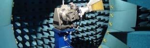
25 Linear Array Antennas Measurement System An ad-hoc measurement system designed and built for linear antennas by GR UPM for INDRA. The AUT is fixed on the structure. The probe moves along the linear slide, stopping in front of each array element, acquiring the near field radiated by the AUT (in amplitude and phase). This acquired field is processed to obtain the radiation pattern in the far field for the plane of the array. A post-processing is performed to obtain the radiation pattern main parameters. The measurement range is formed by the following main subsystems: Linear slide and antenna array supporting structure. Anechoic and reflector systems, including an elevator for antenna array installation. Radio frequency subsystem. The system also includes an ad-hoc acquisition, processing and representation software. 49 Linear Array Antennas Measurement System 50
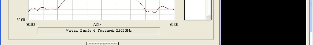
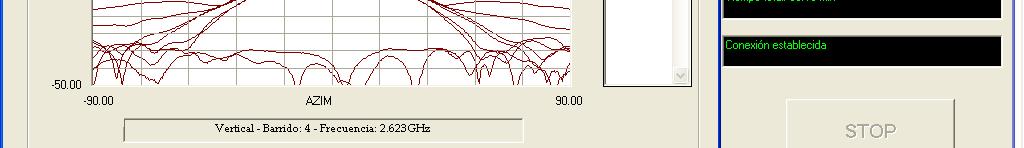
26 CEAR Cylindrical Near-Field Range 51 CEAR Cylindrical Near-Field Range System designed and built by GR UPM Geometric features: Tower length: meters Tower usable length: 15.7 meters Distance between AUT axe and Probe: 5.5 or 7.5 meters 15.7 m Operation requirements: Frequency Range: L band ( MHz) 69.1º m System S t can workk in i windy i d situations it ti (< 30 kkm/h) /h) 5.35 m Error tolerances: 3.71 m 33.2º Directivity maximum error: 0.5 db SLL Error at 30 db: 2 db SLL Error at 40 db: 3 db Azimuth Beam Pointing Error: 0.05º ~1 m 3.42 m Elevation Beam Pointing Error: 0.1º 52
27 CEAR KEY POINTS Optimized i acquisition iti process 2 Polarizations 2 Radiation Patterns (monopulse curves) Z axis linearity ensured by an automatic laser based system Residual error <±1mm Temperature drifts corrected by a hw-sw system CEAR XY POSITIONING ERROR CORRECTION 2000 ERRORES DE POSICIONAMIENTO EN EL EJE X 1500 MORORIZED xy TABLE 1000 QUADRANT DETECTOR 500 TOWE R Err ror en micras 0 LASER -500 AND OPTICAL PLUMMBET Altura en cm 54

")


28 Systems for small antennas (mobile) EPFL-LEMA system (Lausanne - Switzerland) Chalmers-Bluetest system (Göteborg Sweeden) 55 SATIMO Stargate System Acquisition & Processing Stargate system made of 64 probes Probe Calibration 56


29 MVG Large Measurement System 57 Millilab Hologram based CATR for 650 GHz 58


30 Reverberation chamber For radiation efficient measurements (among other applications): Bluetest Chamber Magdeburg large reverberation chamber 59 RCS measurements 60
31 RCS measurements 61 RCS bistatic measurements 62
32 Acquisition, Processing and Representation Software 63 Software PROCENCA (GR-UPM) Measurement definition 64


33 Software PROCENCA (GR-UPM) Acquisition 65 Software PROCENCA (GR-UPM) Results definition 66
34 Software PROCENCA (GR-UPM) Results 67
Antenna Measurements: Fundamentals and Advanced Techniques
 : Fundamentals and Advanced Techniques 4 th International Travelling Summer School on Microwaves and Lightwaves July 5-11, 014, Copenhagen, Denmark Sergey Pivnenko Department of Electrical Engineering
Introduction Antenna Ranges Radiation Patterns Gain Measurements Directivity Measurements Impedance Measurements Polarization Measurements Scale
 Chapter 17 : Antenna Measurement Introduction Antenna Ranges Radiation Patterns Gain Measurements Directivity Measurements Impedance Measurements Polarization Measurements Scale Model Measurements 1 Introduction
Main features. System configurations. I Compact Range SOLUTION FOR
 Compact Range + Direct far-field measurement of electrically large antennas SOLUTION FOR Antenna measurement Radome measurement RCS measurement A Compact Range makes direct far-field measurement of electrically
Estimating Measurement Uncertainties in Compact Range Antenna Measurements
 Estimating Measurement Uncertainties in Compact Range Antenna Measurements Stephen Blalock & Jeffrey A. Fordham MI Technologies Suwanee, Georgia, USA sblalock@mitechnologies.com jfordham@mitechnolgies.com
GAIN COMPARISON MEASUREMENTS IN SPHERICAL NEAR-FIELD SCANNING
 GAIN COMPARISON MEASUREMENTS IN SPHERICAL NEAR-FIELD SCANNING ABSTRACT by Doren W. Hess and John R. Jones Scientific-Atlanta, Inc. A set of near-field measurements has been performed by combining the methods
Antennas & Measurement of its parameters
 Antennas & Measurement of its parameters Chandana Viswanadham SDGM (D&E), Bharat Electronics, IE, Nacharam, Hyderabad 500 076 ABSTRACT As all of us aware, a communication system comprises Transmitter,
Antenna Theory and Design
 Antenna Theory and Design Antenna Theory and Design Associate Professor: WANG Junjun 王珺珺 School of Electronic and Information Engineering, Beihang University F1025, New Main Building wangjunjun@buaa.edu.cn
Introduction to Radar Systems. Radar Antennas. MIT Lincoln Laboratory. Radar Antennas - 1 PRH 6/18/02
 Introduction to Radar Systems Radar Antennas Radar Antennas - 1 Disclaimer of Endorsement and Liability The video courseware and accompanying viewgraphs presented on this server were prepared as an account
Further Refining and Validation of RF Absorber Approximation Equations for Anechoic Chamber Predictions
 Further Refining and Validation of RF Absorber Approximation Equations for Anechoic Chamber Predictions Vince Rodriguez, NSI-MI Technologies, Suwanee, Georgia, USA, vrodriguez@nsi-mi.com Abstract Indoor
HOW TO CHOOSE AN ANTENNA RANGE CONFIGURATION
 HOW TO CHOOSE AN ANTENNA RANGE CONFIGURATION Donnie Gray Nearfield Systems, Inc. 1330 E. 223 rd St, Bldg 524 Carson, CA 90745 (310) 518-4277 dgray@nearfield.com Abstract Choosing the proper antenna range
KULLIYYAH OF ENGINEERING
 KULLIYYAH OF ENGINEERING DEPARTMENT OF ELECTRICAL & COMPUTER ENGINEERING ANTENNA AND WAVE PROPAGATION LABORATORY (ECE 4103) EXPERIMENT NO 3 RADIATION PATTERN AND GAIN CHARACTERISTICS OF THE DISH (PARABOLIC)
Antenna Measurement Uncertainty Method for Measurements in Compact Antenna Test Ranges
 Antenna Measurement Uncertainty Method for Measurements in Compact Antenna Test Ranges Stephen Blalock & Jeffrey A. Fordham MI Technologies Suwanee, Georgia, USA Abstract Methods for determining the uncertainty
SPHERICAL NEAR-FIELD MEASUREMENTS AT UHF FREQUENCIES WITH COMPLETE UNCERTAINTY ANALYSIS
 SPHERICAL NEAR-FIELD MEASUREMENTS AT UHF FREQUENCIES WITH COMPLETE UNCERTAINTY ANALYSIS Allen Newell, Patrick Pelland Nearfield Systems Inc. 19730 Magellan Drive, Torrance, CA 90502-1104 Brian Park, Ted
A DUAL-PORTED PROBE FOR PLANAR NEAR-FIELD MEASUREMENTS
 A DUAL-PORTED PROBE FOR PLANAR NEAR-FIELD MEASUREMENTS W. Keith Dishman, Doren W. Hess, and A. Renee Koster ABSTRACT A dual-linearly polarized probe developed for use in planar near-field antenna measurements
Keywords: cylindrical near-field acquisition, mechanical and electrical errors, uncertainty, directivity.
 UNCERTAINTY EVALUATION THROUGH SIMULATIONS OF VIRTUAL ACQUISITIONS MODIFIED WITH MECHANICAL AND ELECTRICAL ERRORS IN A CYLINDRICAL NEAR-FIELD ANTENNA MEASUREMENT SYSTEM S. Burgos, M. Sierra-Castañer, F.
Dr. John S. Seybold. November 9, IEEE Melbourne COM/SP AP/MTT Chapters
 Antennas Dr. John S. Seybold November 9, 004 IEEE Melbourne COM/SP AP/MTT Chapters Introduction The antenna is the air interface of a communication system An antenna is an electrical conductor or system
ANTENNA INTRODUCTION / BASICS
 Rules of Thumb: 1. The Gain of an antenna with losses is given by: G 0A 8 Where 0 ' Efficiency A ' Physical aperture area 8 ' wavelength ANTENNA INTRODUCTION / BASICS another is:. Gain of rectangular X-Band
CHAPTER 5 THEORY AND TYPES OF ANTENNAS. 5.1 Introduction
 CHAPTER 5 THEORY AND TYPES OF ANTENNAS 5.1 Introduction Antenna is an integral part of wireless communication systems, considered as an interface between transmission line and free space [16]. Antenna
NTT DOCOMO Technical Journal. Method for Measuring Base Station Antenna Radiation Characteristics in Anechoic Chamber. 1.
 Base Station Antenna Directivity Gain Method for Measuring Base Station Antenna Radiation Characteristics in Anechoic Chamber Base station antennas tend to be long compared to the wavelengths at which
Aperture antennas. Ahmed FACHAR, Universidad Politécnica de Madrid (Technical University of Madrid, UPM)
") Aperture antennas Ahmed FACHAR, ahmedfach@gr.ssr.upm.es Universidad Politécnica de Madrid (Technical University of Madrid, UPM) Outline Introduction Horn antennas Introduction Rectangular horns Conical
Aperture antennas Ahmed FACHAR, ahmedfach@gr.ssr.upm.es Universidad Politécnica de Madrid (Technical University of Madrid, UPM) Outline Introduction Horn antennas Introduction Rectangular horns Conical
Antenna Measurement Theory
 Introduction to Antenna Measurement 1. Basic Concepts 1.1 ELECTROMAGNETIC WAVES The radiation field from a transmitting antenna is characterized by the complex Poynting vector E x H* in which E is the
Implementation of a VHF Spherical Near-Field Measurement Facility at CNES
 Implementation of a VHF Spherical Near-Field Measurement Facility at CNES Gwenn Le Fur, Guillaume Robin, Nicolas Adnet, Luc Duchesne R&D Department MVG Industries Villebon-sur-Yvette, France Gwenn.le-fur@satimo.fr
REPORT ITU-R BT Radiation pattern characteristics of UHF * television receiving antennas
 Rep. ITU-R BT.2138 1 REPORT ITU-R BT.2138 Radiation pattern characteristics of UHF * television receiving antennas (2008) 1 Introduction This Report describes measurements of the radiation pattern characteristics
Fundamentals. Senior Project Manager / AEO Taiwan. Philip Chang
 mmwave OTA Fundamentals Senior Project Manager / AEO Taiwan Philip Chang L A R G E LY D R I V E N B Y N E W W I R E L E S S T E C H N O L O G I E S A N D F R E Q U E N C Y B A N D S 1. Highly integrated
ANTENNA INTRODUCTION / BASICS
 ANTENNA INTRODUCTION / BASICS RULES OF THUMB: 1. The Gain of an antenna with losses is given by: 2. Gain of rectangular X-Band Aperture G = 1.4 LW L = length of aperture in cm Where: W = width of aperture
Antennas and Propagation. Chapter 4: Antenna Types
 Antennas and Propagation : Antenna Types 4.4 Aperture Antennas High microwave frequencies Thin wires and dielectrics cause loss Coaxial lines: may have 10dB per meter Waveguides often used instead Aperture
Conventional measurement systems
 Conventional measurement systems NEAR FIELD Near-field measurement is suitable for a variety of antennas, from small antennas in compact electronic devices to very large phased array antennas. Planar near-field
An Introduction to Antennas
 May 11, 010 An Introduction to Antennas 1 Outline Antenna definition Main parameters of an antenna Types of antennas Antenna radiation (oynting vector) Radiation pattern Far-field distance, directivity,
Accurate Planar Near-Field Results Without Full Anechoic Chamber
 Accurate Planar Near-Field Results Without Full Anechoic Chamber Greg Hindman, Stuart Gregson, Allen Newell Nearfield Systems Inc. Torrance, CA, USA ghindman@nearfield.com Abstract - Planar near-field
Principles of Planar Near-Field Antenna Measurements. Stuart Gregson, John McCormick and Clive Parini. The Institution of Engineering and Technology
 Principles of Planar Near-Field Antenna Measurements Stuart Gregson, John McCormick and Clive Parini The Institution of Engineering and Technology Contents Preface xi 1 Introduction 1 1.1 The phenomena
RAYTHEON 23 x 22 50GHZ PULSE SYSTEM
 RAYTHEON 23 x 22 50GHZ PULSE SYSTEM Terry Speicher Nearfield Systems, Incorporated 1330 E. 223 rd Street, Bldg. 524 Carson, CA 90745 www.nearfield.com Angelo Puzella and Joseph K. Mulcahey Raytheon Electronic
A COMPOSITE NEAR-FIELD SCANNING ANTENNA RANGE FOR MILLIMETER-WAVE BANDS
 A COMPOSITE NEAR-FIELD SCANNING ANTENNA RANGE FOR MILLIMETER-WAVE BANDS Doren W. Hess dhess@mi-technologies.com John McKenna jmckenna@mi-technologies.com MI-Technologies 1125 Satellite Boulevard Suite
EEM.Ant. Antennas and Propagation
 EEM.ant/0304/08pg/Req: None 1/8 UNIVERSITY OF SURREY Department of Electronic Engineering MSc EXAMINATION EEM.Ant Antennas and Propagation Duration: 2 Hours Spring 2003/04 READ THESE INSTRUCTIONS Answer
Half-Wave Dipole. Radiation Resistance. Antenna Efficiency
 Antennas Simple Antennas Isotropic radiator is the simplest antenna mathematically Radiates all the power supplied to it, equally in all directions Theoretical only, can t be built Useful as a reference:
Software. Equipment. Add-ons. Accessories. Services
 T- DualScan FScan FScan is a vertical near-field planar scanner system that is a perfect solution for antenna measurement applications where a phased array, high gain, or reflector antenna is under evaluation.
PRACTICAL GAIN MEASUREMENTS
 PRACTICAL GAIN MEASUREMENTS Marion Baggett MI Technologies 1125 Satellite Boulevard Suwanee, GA 30022 mbaggett@mi-technologies.com ABSTRACT Collecting accurate gain measurements on antennas is one of the
ANECHOIC CHAMBER DIAGNOSTIC IMAGING
 ANECHOIC CHAMBER DIAGNOSTIC IMAGING Greg Hindman Dan Slater Nearfield Systems Incorporated 1330 E. 223rd St. #524 Carson, CA 90745 USA (310) 518-4277 Abstract Traditional techniques for evaluating the
Accuracy Estimation of Microwave Holography from Planar Near-Field Measurements
 Accuracy Estimation of Microwave Holography from Planar Near-Field Measurements Christopher A. Rose Microwave Instrumentation Technologies River Green Parkway, Suite Duluth, GA 9 Abstract Microwave holography
Aperture Antennas. Reflectors, horns. High Gain Nearly real input impedance. Huygens Principle
 Antennas 97 Aperture Antennas Reflectors, horns. High Gain Nearly real input impedance Huygens Principle Each point of a wave front is a secondary source of spherical waves. 97 Antennas 98 Equivalence
T- DualScan. StarLab
 T- DualScan StarLab StarLab is the ultimate tool for antenna pattern measurements in laboratories and production environments where space is limited, cost is critical, and the flexibility of a portable
> StarLab. Multi-purpose Antenna Measurement Multi-protocol Antenna Development Linear Array Antenna Measurement OTA Testing
 TECHNOLOGY Near-field / Spherical Near-field / Cylindrical SOLUTIONS FOR Multi-purpose Antenna Measurement Multi-protocol Antenna Development Linear Array Antenna Measurement OTA Testing 18 StarLab: a
ANTENNA THEORY. Analysis and Design. CONSTANTINE A. BALANIS Arizona State University. JOHN WILEY & SONS New York Chichester Brisbane Toronto Singapore
 ANTENNA THEORY Analysis and Design CONSTANTINE A. BALANIS Arizona State University JOHN WILEY & SONS New York Chichester Brisbane Toronto Singapore Contents Preface xv Chapter 1 Antennas 1 1.1 Introduction
Chapter 2. Fundamental Properties of Antennas. ECE 5318/6352 Antenna Engineering Dr. Stuart Long
 Chapter Fundamental Properties of Antennas ECE 5318/635 Antenna Engineering Dr. Stuart Long 1 IEEE Standards Definition of Terms for Antennas IEEE Standard 145-1983 IEEE Transactions on Antennas and Propagation
System configurations. Main features. I TScan SOLUTION FOR
 TScan TScan is a fast and ultra-accurate planar near-field scanner with the latest motor drive and encoder technologies. High acceleration of the linear motors for stepped and continuous mode operation
60 GHz antenna measurement setup using a VNA without external frequency conversion
 Downloaded from orbit.dtu.dk on: Mar 11, 2018 60 GHz antenna measurement setup using a VNA without external frequency conversion Popa, Paula Irina; Pivnenko, Sergey; Bjørstorp, Jeppe Majlund; Breinbjerg,
The LACE Antenna Test Ranges
 Politecnico di Torino The LACE Antenna Test Ranges 1. Introduction Politecnico di Torino is the oldest Technical University in Italy, with more than one and a half centuries of academic activity. It is
The Importance of Polarization Purity Author: Lars J Foged, Scientific Director at MVG (Microwave Vision Group)
") The Importance of Polarization Purity Author: Lars J Foged, Scientific Director at MVG (Microwave Vision Group) The polarization purity of an antenna system is an important characteristic, particularly
The Importance of Polarization Purity Author: Lars J Foged, Scientific Director at MVG (Microwave Vision Group) The polarization purity of an antenna system is an important characteristic, particularly
Notes 21 Introduction to Antennas
 ECE 3317 Applied Electromagnetic Waves Prof. David R. Jackson Fall 018 Notes 1 Introduction to Antennas 1 Introduction to Antennas Antennas An antenna is a device that is used to transmit and/or receive
ANECHOIC CHAMBER EVALUATION
 ANECHOIC CHAMBER EVALUATION Antenna Measurement Techniques Association Conference October 3 - October 7, 1994 Karl Haner Nearfield Systems Inc. 1330 E. 223rd Street Bldg.524 Carson, CA 90745 USA (310)
Differential and Single Ended Elliptical Antennas for GHz Ultra Wideband Communication
 Differential and Single Ended Elliptical Antennas for 3.1-1.6 GHz Ultra Wideband Communication Johnna Powell Anantha Chandrakasan Massachusetts Institute of Technology Microsystems Technology Laboratory
Antenna Engineering Lecture 3: Basic Antenna Parameters
 Antenna Engineering Lecture 3: Basic Antenna Parameters ELC 405a Fall 2011 Department of Electronics and Communications Engineering Faculty of Engineering Cairo University 2 Outline 1 Radiation Pattern
Anexo 2 ASYTRAIN. Antenna Training Kit Lab. Antenna design, development and test
 Anexo 2 ASYTRAIN Antenna Training Kit Lab Antenna design, development and test 1 SCOPE The following document is an outline of Radiation Group s latest training product ASYTRAIN. The package is a collection
WIESON TECHNOLOGIES CO., LTD.
 WIESON 3D CHAMBER TEST REPORT G121HT632-1 Page 1 of 2 I. Summary: This report to account for the measurement setup and result of the Antenna. The measurement setup includes s-parameter, pattern, and gain
TRANSMITTING ANTENNA WITH DUAL CIRCULAR POLARISATION FOR INDOOR ANTENNA MEASUREMENT RANGE
 TRANSMITTING ANTENNA WITH DUAL CIRCULAR POLARISATION FOR INDOOR ANTENNA MEASUREMENT RANGE Michal Mrnka, Jan Vélim Doctoral Degree Programme (2), FEEC BUT E-mail: xmrnka01@stud.feec.vutbr.cz, velim@phd.feec.vutbr.cz
Over the Air Testing: Important Antenna Parameters, Testing Methodologies and Standards
 Over the Air Testing: Important Antenna Parameters, Testing Methodologies and Standards Alexander Naehring Rohde & Schwarz GmbH & Co. KG Muehldorfstr. 15, 81671 Munich, Germany Email: alexander.naehring@rohde-schwarz.com
BROADBAND GAIN STANDARDS FOR WIRELESS MEASUREMENTS
 BROADBAND GAIN STANDARDS FOR WIRELESS MEASUREMENTS James D. Huff Carl W. Sirles The Howland Company, Inc. 4540 Atwater Court, Suite 107 Buford, Georgia 30518 USA Abstract Total Radiated Power (TRP) and
Aperture antennas. Andrés García, Francico José Cano, Alfonso Muñoz. (Technical University of Madrid, UPM)
") Aperture antennas Andrés García, Francico José Cano, Alfonso Muñoz andresg@gr.ssr.upm.es, ssr francisco@gr.ssr.upm.es, ssr alfonso@gr.ssr.upm.esssr Universidad Politécnica de Madrid (Technical University
Aperture antennas Andrés García, Francico José Cano, Alfonso Muñoz andresg@gr.ssr.upm.es, ssr francisco@gr.ssr.upm.es, ssr alfonso@gr.ssr.upm.esssr Universidad Politécnica de Madrid (Technical University
MISSION TO MARS - IN SEARCH OF ANTENNA PATTERN CRATERS
 MISSION TO MARS - IN SEARCH OF ANTENNA PATTERN CRATERS Greg Hindman & Allen C. Newell Nearfield Systems Inc. 197 Magellan Drive Torrance, CA 92 ABSTRACT Reflections in anechoic chambers can limit the performance
Range Considerations for RF Networks
 TI Technology Days 2010 Range Considerations for RF Networks Richard Wallace Abstract The antenna can be one of the most daunting components of wireless designs. Most information available relates to large
Absorbers and Anechoic Chamber Measurements
 Absorbers and Anechoic Chamber Measurements Zhong Chen Director, RF Engineering ETS-Lindgren 1301 Arrow Point Dr. Cedar Park, TX, 78613 Zhong.chen@ets-lindgren.com SUMMARY Absorber Overviews Absorber Materials
Final Examination. 22 April 2013, 9:30 12:00. Examiner: Prof. Sean V. Hum. All non-programmable electronic calculators are allowed.
 UNIVERSITY OF TORONTO FACULTY OF APPLIED SCIENCE AND ENGINEERING The Edward S. Rogers Sr. Department of Electrical and Computer Engineering ECE 422H1S RADIO AND MICROWAVE WIRELESS SYSTEMS Final Examination
A LABORATORY COURSE ON ANTENNA MEASUREMENT
 A LABORATORY COURSE ON ANTENNA MEASUREMENT Samuel Parker Raytheon Systems Company, 2000 East Imperial Highway RE/R02/V509, El Segundo, CA 90245 Dean Arakaki Electrical Engineering Department, California
Absorbers and Anechoic Chamber Measurements
 Absorbers and Anechoic Chamber Measurements Zhong Chen Director, RF Engineering ETS-Lindgren 1301 Arrow Point Dr. Cedar Park, TX, 78613 Zhong.chen@ets-lindgren.com SUMMARY Absorber Overview Absorber Materials
INDOOR AUTOMATIC F-16 FIRE CONTROL ANTENNA AND RADOME TEST FACILITIES
 INDOOR AUTOMATIC F-16 FIRE CONTROL ANTENNA AND RADOME TEST FACILITIES ABSTRACT by Joseph J. Anderson MI Technologies was selected by the United States Air Force to design and install a complete turn-key
LE/ESSE Payload Design
 LE/ESSE4360 - Payload Design 4.3 Communications Satellite Payload - Hardware Elements Earth, Moon, Mars, and Beyond Dr. Jinjun Shan, Professor of Space Engineering Department of Earth and Space Science
Near-Field Antenna Measurements using a Lithium Niobate Photonic Probe
 Near-Field Antenna Measurements using a Lithium Niobate Photonic Probe Vince Rodriguez 1, Brett Walkenhorst 1, and Jim Toney 2 1 NSI-MI Technologies, Suwanee, Georgia, USA, Vrodriguez@nsi-mi.com 2 Srico,
Module contents. Antenna systems. RF propagation. RF prop. 1
 Module contents Antenna systems RF propagation RF prop. 1 Basic antenna operation Dipole Antennas are specific to Frequency based on dimensions of elements 1/4 λ Dipole (Wire 1/4 of a Wavelength) creates
HHTEHHH THEORY ANALYSIS AND DESIGN. CONSTANTINE A. BALANIS Arizona State University
 HHTEHHH THEORY ANALYSIS AND DESIGN CONSTANTINE A. BALANIS Arizona State University JOHN WILEY & SONS, INC. New York Chichester Brisbane Toronto Singapore Contents Preface V CHAPTER 1 ANTENNAS 1.1 Introduction
Escuela Técnica Superior de Ingenieros de Telecomunicación de la Universidad Politécnica de Madrid. Avenida Complutense nº30, Madrid (SPAIN)
") Presentation of the background of the Radiation Group of the Technical University of Madrid (GR UPM) Escuela Técnica Superior de Ingenieros de Telecomunicación de la Universidad Politécnica de Madrid.
Presentation of the background of the Radiation Group of the Technical University of Madrid (GR UPM) Escuela Técnica Superior de Ingenieros de Telecomunicación de la Universidad Politécnica de Madrid.
BHARATHIDASAN ENGINEERING COLLEGE NATTARAMPALLI Frequently Asked Questions (FAQ) Unit 1
 Unit 1") BHARATHIDASAN ENGINEERING COLLEGE NATTARAMPALLI 635854 Frequently Asked Questions (FAQ) Unit 1 Degree / Branch : B.E / ECE Sem / Year : 3 rd / 6 th Sub Name : Antennas & Wave Propagation Sub Code : EC6602
BHARATHIDASAN ENGINEERING COLLEGE NATTARAMPALLI 635854 Frequently Asked Questions (FAQ) Unit 1 Degree / Branch : B.E / ECE Sem / Year : 3 rd / 6 th Sub Name : Antennas & Wave Propagation Sub Code : EC6602
Antenna & Propagation. Antenna Parameters
 For updated version, please click on http://ocw.ump.edu.my Antenna & Propagation Antenna Parameters by Nor Hadzfizah Binti Mohd Radi Faculty of Electric & Electronics Engineering hadzfizah@ump.edu.my Chapter
APPLICATIONS OF PORTABLE NEAR-FIELD ANTENNA MEASUREMENT SYSTEMS
 APPLICATIONS OF PORTABLE NEAR-FIELD ANTENNA MEASUREMENT SYSTEMS Greg Hindman Nearfield Systems Inc. 1330 E. 223rd Street Bldg. 524 Carson, CA 90745 (213) 518-4277 ABSTRACT Portable near-field measurement
ANTENNAS AND WAVE PROPAGATION EC602
 ANTENNAS AND WAVE PROPAGATION EC602 B.Tech Electronics & Communication Engineering, Semester VI INSTITUTE OF TECHNOLOGY NIRMA UNIVERSITY 1 Lesson Planning (L-3,P-2,C-4) Chapter No. Name Hours 1. Basic
EMG4066:Antennas and Propagation Exp 1:ANTENNAS MMU:FOE. To study the radiation pattern characteristics of various types of antennas.
 OBJECTIVES To study the radiation pattern characteristics of various types of antennas. APPARATUS Microwave Source Rotating Antenna Platform Measurement Interface Transmitting Horn Antenna Dipole and Yagi
required. The inside enclosure is then covered with a radiowave absorber to reduce reflections. Such an
 APPENDIX II PERFORNMNOE EVALUATION OF A MICROWAVE ANECHOIC CHAMBER.'.v Antenna measurements, Ii scattering experiments etc. have to be conducted in an environment free from radio signal interference. Generally
UNIT Explain the radiation from two-wire. Ans: Radiation from Two wire
 UNIT 1 1. Explain the radiation from two-wire. Radiation from Two wire Figure1.1.1 shows a voltage source connected two-wire transmission line which is further connected to an antenna. An electric field
HYBRID ARRAY ANTENNA FOR BROADBAND MILLIMETER-WAVE APPLICATIONS
 Progress In Electromagnetics Research, PIER 83, 173 183, 2008 HYBRID ARRAY ANTENNA FOR BROADBAND MILLIMETER-WAVE APPLICATIONS S. Costanzo, I. Venneri, G. Di Massa, and G. Amendola Dipartimento di Elettronica,
This paper examines Massive MIMO measurements. Massive MIMO is a technology using a very large number of antenna elements to support multi-user MIMO t
 s Over The Air measurement will become important in the coming fifth-generation mobile communication technologies (5G) because of introduction of massive MIMO at micro-wave and millimeter-wave frequencies
Chapter-9 CONCLUSIONS AND FUTURE SCOPE
 Chapter-9 CONCLUSIONS AND FUTURE SCOPE 9.1 CONCLUSIONS This thesis presented a detailed study about six different new antenna designs developed to demonstrate the reconfigurable concept employing electrical
A TECHNIQUE TO EVALUATE THE IMPACT OF FLEX CABLE PHASE INSTABILITY ON mm-wave PLANAR NEAR-FIELD MEASUREMENT ACCURACIES
 A TECHNIQUE TO EVALUATE THE IMPACT OF FLEX CABLE PHASE INSTABILITY ON mm-wave PLANAR NEAR-FIELD MEASUREMENT ACCURACIES Daniël Janse van Rensburg Nearfield Systems Inc., 133 E, 223rd Street, Bldg. 524,
IMPLEMENTATION OF BACK PROJECTION ON A SPHERICAL NEAR- FIELD RANGE
 IMPLEMENTATION OF BACK PROJECTION ON A SPHERICAL NEAR- FIELD RANGE Daniël Janse van Rensburg & Chris Walker* Nearfield Systems Inc, Suite 24, 223 rd Street, Carson, CA, USA Tel: (613) 27 99 Fax: (613)
Antennas & wave Propagation ASSIGNMENT-I
 Shri Vishnu Engineering College for Women :: Bhimavaram Department of Electronics & Communication Engineering Antennas & wave Propagation 1. Define the terms: i. Antenna Aperture ii. Beam Width iii. Aperture
Antenna Fundamentals Basics antenna theory and concepts
 Antenna Fundamentals Basics antenna theory and concepts M. Haridim Brno University of Technology, Brno February 2017 1 Topics What is antenna Antenna types Antenna parameters: radiation pattern, directivity,
Antenna Measurement using Vector Network Analyzer. Jong-hwan Keum Agilent Technologies
 Antenna Measurement using Vector Network Analyzer Jong-hwan Keum Agilent Technologies Agenda Overview Antenna Measurement System Configuration(Examples) Antenna Measurement System Design Considerations
Uncertainty Considerations In Spherical Near-field Antenna Measurements
 Uncertainty Considerations In Spherical Near-field Antenna Measurements Phil Miller National Physical Laboratory Industry & Innovation Division Teddington, United Kingdom Outline Introduction and Spherical
RECOMMENDATION ITU-R S *
 Rec. ITU-R S.1339-1 1 RECOMMENDATION ITU-R S.1339-1* Rec. ITU-R S.1339-1 SHARING BETWEEN SPACEBORNE PASSIVE SENSORS OF THE EARTH EXPLORATION-SATELLITE SERVICE AND INTER-SATELLITE LINKS OF GEOSTATIONARY-SATELLITE
Upgraded Planar Near-Field Test Range For Large Space Flight Reflector Antennas Testing from L to Ku-Band
 Upgraded Planar Near-Field Test Range For Large Space Flight Reflector Antennas Testing from L to Ku-Band Laurent Roux, Frédéric Viguier, Christian Feat ALCATEL SPACE, Space Antenna Products Line 26 avenue
A CYLINDRICAL NEAR-FIELD VS. SPHERICAL NEAR-FIELD ANTENNA TEST COMPARISON
 A CYLINDRICAL NEAR-FIELD VS. SPHERICAL NEAR-FIELD ANTENNA TEST COMPARISON Jeffrey Fordham VP, Sales and Marketing MI Technologies, 4500 River Green Parkway, Suite 200 Duluth, GA 30096 jfordham@mi-technologies.com
System configurations. Main features I SG 64 SOLUTION FOR
 T- DualScan SG 64 The most accurate solution for testing antennas and wireless devices: SG 64 has been developed to measure stand alone antennas or antennas integrated in subsystems. It is also ideal for
Design and Test of a 0.3 THz Compact Antenna Test Range
 Progress In Electromagnetics Research Letters, Vol. 70, 81 87, 2017 Design and Test of a 0.3 THz Compact Antenna Test Range Chi Liu * and Xuetian Wang Abstract The terahertz (THz) compact antenna test
INSTITUTE OF AERONAUTICAL ENGINEERING Dundigal, Hyderabad ELECTRONICS AND COMMUNIACTION ENGINEERING QUESTION BANK
 INSTITUTE OF AERONAUTICAL ENGINEERING Dundigal, Hyderabad - 500 04 ELECTRONICS AND COMMUNIACTION ENGINEERING QUESTION BANK Course Name : Antennas and Wave Propagation (AWP) Course Code : A50418 Class :
REVERBERATION CHAMBER FOR EMI TESTING
 1 REVERBERATION CHAMBER FOR EMI TESTING INTRODUCTION EMI Testing 1. Whether a product is intended for military, industrial, commercial or residential use, while it must perform its intended function in
Travelling Wave, Broadband, and Frequency Independent Antennas. EE-4382/ Antenna Engineering
 Travelling Wave, Broadband, and Frequency Independent Antennas EE-4382/5306 - Antenna Engineering Outline Traveling Wave Antennas Introduction Traveling Wave Antennas: Long Wire, V Antenna, Rhombic Antenna
ELEC 425 Interference Control in Electronics Lecture 7(a) Introduction to Antennas: Terminology
 Introduction to Antennas: Terminology") Dr. Gregory J. Mazzaro Fall 017 ELEC 45 Interference Control in Electronics Lecture 7(a) Introduction to Antennas: Terminology Chapter 9 THE CITADEL, THE MILITARY COLLEGE OF SOUTH CAROLINA 171 Moultrie
Dr. Gregory J. Mazzaro Fall 017 ELEC 45 Interference Control in Electronics Lecture 7(a) Introduction to Antennas: Terminology Chapter 9 THE CITADEL, THE MILITARY COLLEGE OF SOUTH CAROLINA 171 Moultrie
33 BY 16 NEAR-FIELD MEASUREMENT SYSTEM
 33 BY 16 NEAR-FIELD MEASUREMENT SYSTEM ABSTRACT Nearfield Systems Inc. (NSI) has delivered the world s largest vertical near-field measurement system. With a 30m by 16m scan area and a frequency range
18th International Symposium on Space Terahertz Technology. Measurement of a high-gain antenna at 650 GHz in a hologram-based CATR
 Measurement of a high-gain antenna at 650 GHz in a hologram-based CATR A.V. Räisänen, J. Ala-Laurinaho, J. Häkli, A. Karttunen, T. Koskinen, A. Lönnqvist, J. Mallat, E. Noponen, A. Tamminen, M. Vaaja,
Fundamentals of Antennas. Prof. Ely Levine
 Fundamentals of Antennas Prof. Ely Levine levineel@zahav.net.il 1 Chapter 3 Wire Antennas 2 Types of Antennas 3 Isotropic Antenna Isotropic radiator is the simplest antenna mathematically Radiates all
A Compact Dual-Band Dual-Polarized Antenna for Base Station Application
 Progress In Electromagnetics Research C, Vol. 64, 61 70, 2016 A Compact Dual-Band Dual-Polarized Antenna for Base Station Application Guanfeng Cui 1, *, Shi-Gang Zhou 2,GangZhao 1, and Shu-Xi Gong 1 Abstract
Projects LOTHAR and LOTHAR-fatt
 Appendix B Projects LOTHAR and LOTHAR-fatt From 2008 to 2011 the National Laboratory RAdar and Surveillance Systems (RaSS) of the National Inter-universitary Consortium for the Telecommunications (CNIT)
Using Frequency Diversity to Improve Measurement Speed Roger Dygert MI Technologies, 1125 Satellite Blvd., Suite 100 Suwanee, GA 30024
 Using Frequency Diversity to Improve Measurement Speed Roger Dygert MI Technologies, 1125 Satellite Blvd., Suite 1 Suwanee, GA 324 ABSTRACT Conventional antenna measurement systems use a multiplexer or