2016/10/14. YU Xiangyu
|
|
|
- Marian Jocelyn Newton
- 5 years ago
- Views:
Transcription


1 2016/10/14 YU Xiangyu
2
3 Frequency and Spectrum Types of Waves Propagation Model Free-Space Propagation Path Loss Fading: Slow Fading / Fast Fading Doppler Shift Delay Spread
4 FIGURE Electromagnetic frequency spectrum. Wayne Tomasi Electronic Communications Systems, Fourth Edition
5 Tomasi Advanced Electronic Communications Systems, 6e FIGURE Electromagnetic wavelength spectrum
6 Schiller P26 Frequency and wave length = c/f wave length, speed of light c 3x10 8 m/s, frequency f twisted pair coax cable optical transmission 1 Mm 300 Hz 10 km 30 khz 100 m 3 MHz 1 m 300 MHz 10 mm 30 GHz 100 m 3 THz 1 m 300 THz VL F LF M F HF VHF UHF SHF EHF infrared visible UV light
7 Frequency Name Typical application band (khz) 3 30 Very low frequency Long-distance navigation, (VLF) Underwater comm. Sonar Low frequency Navigation, underwater comm. (LF) radio beaconing Medium frequency Broadcasting, maritime comm. (MF) direction-finding, distress calling, coast guard Fan P10-11
8 Frequency Name Typical application band (MHz) 3 30 High frequency Long-distance broadcasting, telegraph, (HF) telephone, fax, search and lifesaving, comm. between aircrafts & ships, and between ship & coast, amateur radio Very high frequency TV, FM broadcasting, land traffic, air (VHF) traffic, control, taxi, police, avigation, aircraft communication Ultra high frequency TV, cellular phone network, microwave (UHF) link,, radio sounding, navigation, satellite communication, GPS, surveillance radar, radio altimeter Fan P11
9 Frequency Name Typical application band (GHz) 3 30 Super high frequency Satellite comm., radio altimeter, (SHF) microwave link, aircraft radar, meteorological radar, public land vehicle communication Extremely high Radar landing system, satellite frequency (EHF) comm., vehicle comm., railway traffic Submillimeter wave Experiment, not designated (0.1 1 mm) Fan P11
10 Frequency Name Typical application band (THz) Infrared (7 0.7 m) Optical communication Visible light ( m) Optical communication Ultraviolet Optical communication ( m) Note: khz = 10 3 Hz, MHz = 10 6 Hz, GHz = 10 9 Hz, THz = Hz, mm = 10-3 m, m = 10-6 m Fan P11
 weather dependent fading, signal loss caused by heavy rainfall etc.")
11 VHF-/UHF-ranges for mobile radio simple, small antenna for cars deterministic propagation characteristics, reliable connections SHF and higher for directed radio links, satellite communication small antenna, beam forming large bandwidth available Wireless LANs use frequencies in UHF to SHF range some systems planned up to EHF limitations due to absorption by, e.g., water (dielectric heating, see microwave oven) weather dependent fading, signal loss caused by heavy rainfall etc. Schiller P26-27
12 Examples Europe USA Japan Cellular networks GSM , , , UMTS , LTE , , Cordless phones CT , CT DECT AMPS, TDMA, CDMA, GSM , TDMA, CDMA, GSM, UMTS , PACS , PACS-UB PDC, FOMA , PDC , FOMA , PHS JCT Wireless LANs b/g b/g b g Other RF systems 27, 128, 418, 433, , , 868 In general: ITU-R holds auctions for new frequencies, manages frequency bands worldwide (WRC, World Radio Conferences); 3GPP specific: see e.g. 3GPP TS V ( ) Schiller P28-29
13 Tomasi Advanced Electronic Communications Systems, 6e TABLE Microwave Radio-Frequency Assignments
14 Classification Band Initials Frequency Range Characteristics Extremely low ELF < 300 Hz Infra low ILF 300 Hz - 3 khz Ground wave Very low VLF 3 khz - 30 khz Low LF 30 khz khz Medium MF 300 khz - 3 MHz Ground/Shy wave High HF 3 MHz - 30 MHz Sky wave Very high VHF 30 MHz MHz Ultra high UHF 300 MHz - 3 GHz Super high SHF 3 GHz - 30 GHz Space wave Extremely high EHF 30 GHz GHz Tremendously high THF 300 GHz GHz Agrawal P33
 Troposphere (0-12 km) Agrawal")
15 Ionosphere ( km) Mesosphere (50-80 km) Space wave Ground wave Earth Stratosphere (12-50 km) Troposphere (0-12 km) Agrawal P33
16 Ground-wave propagation Sky-wave propagation Line-of-sight propagation Figure Propagation of radio frequencies. Couch P41 Stallings P101

17 Tomasi Advanced Electronic Communications Systems, 6e FIGURE Microwave propagation paths
18 Follows contour of the earth Can Propagate considerable distances hundreds to thousands of km Frequencies up to 2 MHz Diffraction Example AM radio Fan P11-12 Stallings P
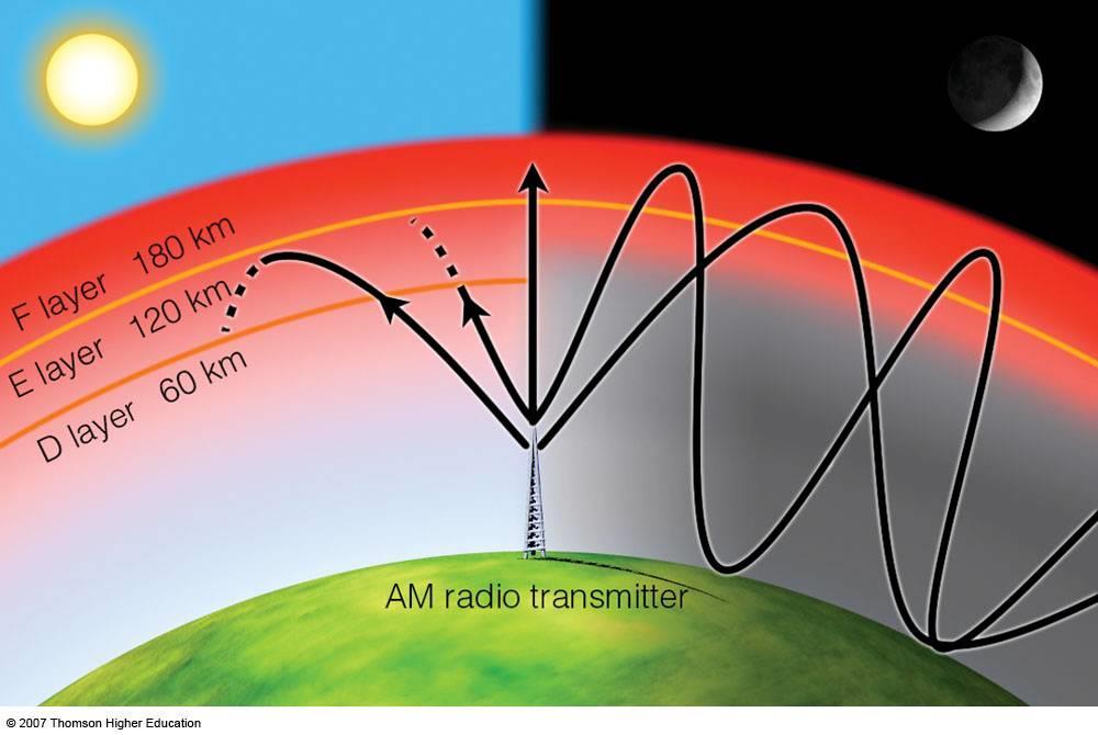
19 Signal reflected from ionized layer of atmosphere back down to earth Signal can travel a number of hops, back and forth between ionosphere(60 ~ 400 km) and earth s surface One hop max. propagation distance:4000 km Propagation distance by multi-hops: >10000 km Reflection effect caused by refraction Frequency:2 ~ 30 MHz Examples Amateur radio CB(Citizens Band) radio Stallings P
20 Wayne Tomasi Electronic Communications Systems, Fourth Edition FIGURE Critical angle

21 D layer: 60 ~ 80 km E layer: 100 ~ 120 km F layer: 150 ~ 400 km F1 layer: 140 ~ 200 km F2 layer: 250 ~ 400 km At night: D layer: disappears F1 layer: disappears (Or, F1 and F2 are combined as F layer)
22 Wayne Tomasi Electronic Communications Systems, Fourth Edition FIGURE Ionospheric layers
23
24 Transmitting and receiving antennas must be within line of sight Satellite communication signal above 30 MHz not reflected by ionosphere Ground communication antennas within effective line of site due to refraction Refraction bending of microwaves by the atmosphere Velocity of electromagnetic wave is a function of the density of the medium When wave changes medium, speed changes Wave bends at the boundary between mediums Stallings P
25 d r ( r h) d 2rh h d h 2rh 2rh Couch P43
26 Optical line of sight d h Effective, or radio, line of sight d h d = distance between antenna and horizon (km) h = antenna height (m) K = adjustment factor to account for refraction, rule of thumb K = 4/3 Stallings P
27 FIGURE Space waves and radio horizon Wayne Tomasi Electronic Communications Systems, Fourth Edition Stallings P103
28 Maximum distance between two antennas for LOS propagation: h 1 = height of antenna one h 2 = height of antenna two 3.57 h h 1 2 Stallings P105

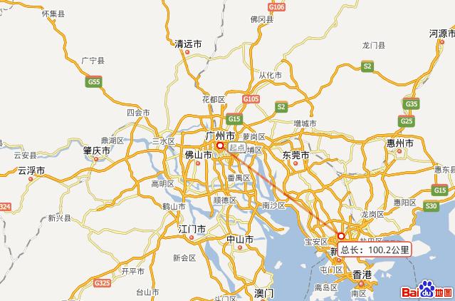
29 My result : 101km

30 Tomasi Advanced Electronic Communications Systems, 6e FIGURE Microwave radio communications link
31 Transmission range communication possible low error rate Detection range detection of the signal possible no communication possible Interference range signal may not be detected sender transmission detection interference signal adds to the background noise Warning: figure misleading bizarre shaped, timevarying ranges in reality! distance Schiller P35-36
32 Propagation in free space always like light (straight line) Receiving power proportional to 1/d² in vacuum much more attenuation in real environments, e.g., d 3.5 d 4 (d = distance between sender and receiver) Receiving power additionally influenced by fading (frequency dependent) shadowing reflection at large obstacles refraction depending on the density of a medium scattering at small obstacles diffraction at edges shadowing reflection refraction scattering diffraction Schiller P37-39

33 Attenuation and attenuation distortion Free space loss Noise Atmospheric absorption Multipath Refraction Thermal noise Stallings P
34 Strength of signal falls off with distance over transmission medium Attenuation factors for unguided media: Received signal must have sufficient strength so that circuitry in the receiver can interpret the signal Signal must maintain a level sufficiently higher than noise to be received without error Attenuation is greater at higher frequencies, causing distortion Stallings P106
35 Attenuation (db/km) Vapor Oxygen Frequency (GHz) (a) Attenuation of oxygen & vapor(concentration 7.5 g/m 3 ) Attenuation (db/km) Rainfall rate Frequency (GHz) (b) Attenuation of rainfall Fan P14
36 The received signal power: GtGr Pt L where P r is the received power, P t is the transmitting power, G r is the receiver antenna gain, G t is the transmitter antenna gain, L is the propagation loss in the channel, i.e., P r L = L P L S L F Fast fading Slow fading Path loss Agrawal P38
37 If a radio channel s propagating characteristics are not specified, one usually infers that the signal attenuation versus distance behaves as if propagation takes place over ideal free space. The model of free space treats the region between the transmit and receive antennas as being free of all objects that might absorb or reflect radio frequency (RF) energy. It also assumes that, within this region, the atmosphere behaves as a perfectly uniform and nonabsorbing medium. Sklar P946
38 Furthermore, the earth is treated as being infinitely far away from the propagating signal (or, equivalently, as having a reflection coefficient that is negligible). Basically, in this idealized free-space model, the attenuation of RF energy between the transmitter and receiver behaves according to an inverse-square law. The received power expressed in terms of transmitted power is attenuated by a factor, where this factor is called path loss or free space loss. Sklar P946
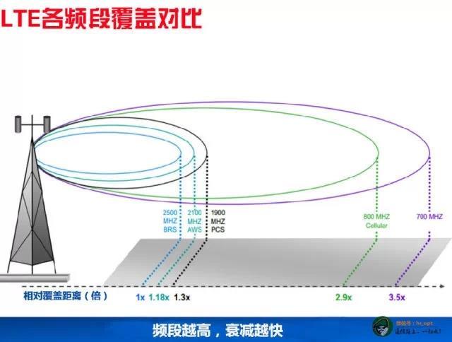
39 Path Loss: The signal strength decays exponentially with distance d between transmitter and receiver; The loss could be proportional to somewhere between d 2 and d 4 depending on the environment. Definition of path loss L P : L P Pt P Path Loss in Free-space: L PF r, ( db) log fc( MHz ) 20log 10 where f c is the carrier frequency. d( 10 km ), This shows greater the f c, more is the loss. Agrawal P36
40 When the receiving antenna is isotropic, this factor is expressed as where d is the distance between the transmitter and the receiver, and is the wavelength of the propagating signal. For this case of idealized propagation, received signal power is very predictable. For most practical channels, where signal propagation takes place in the atmosphere and near the ground, the free-space propagation model is inadequate to describe the channel behavior and predict system performance. Sklar P946
41 Sklar P251
42 h b h m Transmitter Distance d Receiver The received signal power at distance d: P r AeGtP 2 4 d t where P t is transmitting power, A e is effective area, and G t is the transmitting antenna gain. Assuming that the radiated power is uniformly distributed over the surface of the sphere. Agrawal P35-36
43 Antenna gain Power output, in a particular direction, compared to that produced in any direction by a perfect omnidirectional antenna (isotropic antenna) Effective area Related to physical size and shape of antenna Stallings P98-99
44 Relationship between antenna gain and effective area G 4 A e 2 G = antenna gain A e = effective area f = carrier frequency c = speed of light (» m/s) = carrier wavelength 4 f c 2 2 A e 2 A R G R 4 Stallings P100
45 Free space loss, ideal isotropic antenna P t P r 2 4 d 4 fd P t = signal power at transmitting antenna P r = signal power at receiving antenna = carrier wavelength d = propagation distance between antennas c = speed of light (» m/s) where d and are in the same units (e.g., meters) 2 c 2 2 H. T. Friis, "A note on a simple transmission formula," Proc. IRE, vol. 34, pp Stallings P
46 Free space loss equation can be recast: L db 10log Pt P r 20log 4 d 20log d db 20log 4 fd 20log 20log c f 20log d db Stallings P107
47 Free space loss accounting for gain of other antennas P t P r d d cd G G r G t = gain of transmitting antenna G r = gain of receiving antenna A t = effective area of transmitting antenna A r = effective area of receiving antenna t 2 A r A t f 2 A r 2 A t Stallings P107
48 Free space loss accounting for gain of other antennas can be recast as L db 20log d 10log A A 20log t r f 20log d 10log A t A dB 20log r Stallings P107
49 Path Loss in Free-space 130 Path Loss Lf (db) fc=150mhz fc=200mhz fc=400mhz fc=800mhz fc=1000mhz fc=1500mhz Distance d (km) Agrawal P40
50

51
52
53 Simplest Formula: L p = A d α where A and α: propagation constants d : distance between transmitter and receiver α : value of 3 ~ 4 in typical urban area Agrawal P39
54 Path loss in decreasing order: Urban area (large city) Urban area (medium and small city) Suburban area Open area Agrawal P39-40
55 h b =200m, h m =2m Okamura, Y. a kol.: Field Strength and its Variability in VHF and UHF Land-Mobile Radio Service. Rev. Elec. Comm. Lab. No.9-10pp , 1968.
56
 0.8, 2 8.29 log h m for f MHz 101.54 m( ) 1.1, c 200, for 2 3.2 log 11.75h ( m) 4.97, for f 400MHz 10 ( db) L PU m ( db) 2 log 10 2 fc 10 c ( MHz ) 28 10 5.")
57 Urban area: L PU where h m ( db) log ( m) Suburban area: Open area: L PO L PS ( MHz ) 13.82log log h ( m) log d( km) b f c 1.1log 10 fc( MHz ) 0.7 h m( m) 1.56log 10 fc( MHz ) 0.8, log h m for f MHz m( ) 1.1, c 200, for log 11.75h ( m) 4.97, for f 400MHz 10 ( db) L PU m ( db) 2 log 10 2 fc 10 c ( MHz ) h b ( m) h m ( m) small & medium city for l arg e city 2 f ( MHz ) 18.33log f ( MHz ) ( db) LPU ( db) 4.78 log c c Agrawal P39-40
 fc=200mhz fc=400mhz fc=800mhz fc=1000mhz fc=1500mhz fc=150mhz Agrawal")
58 Path Loss in Urban Area in Large City Path Loss Lpu (db) Distance d (km) fc=200mhz fc=400mhz fc=800mhz fc=1000mhz fc=1500mhz fc=150mhz Agrawal P40
59 Path Loss in Urban Area for Small & Medium Cities Path Loss Lpu (db) Distance d (km) fc=150mhz fc=200mhz fc=400mhz fc=800mhz fc=1000mhz fc=1500mhz Agrawal P40
 fc=150mhz fc=200mhz fc=400mhz fc=800mhz fc=1000mhz fc=1500mhz Agrawal")
60 Path Loss in Suburban Area Path Loss Lps (db) Distance d (km) fc=150mhz fc=200mhz fc=400mhz fc=800mhz fc=1000mhz fc=1500mhz Agrawal P40
61 Path Loss in Open Area Path Loss Lpo (db) fc=150mhz fc=200mhz fc=400mhz fc=800mhz fc=1000mhz fc=1500mhz Distance d (km) Agrawal P40
62 Rappaport P152
63 % Code for Simulation Of OKUMURA Model % Code By:- Debaraj Rana % mail- debaraj.rana@ymail.com % Dept. Of Electronics & Telecom. Engg %% VSSUT, Burla,ORISSA clc; clear all; close all; Hte=30:1:100; % Base Station Antenna Height Hre=input('Enter the receiver antenna height 3m<hre<10m : '); % Mobile Antenna Height d =input('enter distance from base station 1Km<d<100Km : '); % Distance 30 Km f=input('enter the frequency 150Mhz<f<1920Mhz : '); c=3*10^8; lamda=(c)/(f*10^6); Lf = 10*log((lamda^2)/((4*pi)^2)*d^2); % Free Space Propagation Loss Amu = 35; % Median Attenuation Relative to Free Space (900 MHz and 30 Km) Garea = 9; % Gain due to the Type of Environment (Suburban Area) Ghte = 20*log(Hte/200); % Base Station Antenna Height Gain Factor if(hre>3) Ghre = 20*log(Hre/3); else Ghre = 10*log(Hre/3); end % Propagation Path Loss L50 = Lf+Amu-Ghte-Ghre-Garea; display('propagation pathloss is : '); disp(l50); plot(hte,l50,'linewidth',1.5); title('okumura Model Analysis'); xlabel('transmitter antenna Height (Km)'); ylabel('propagation Path loss(db) at 50 Km'); grid on; eexchange/28423-okumura-modelsimulation/content/okumura.m
64 Rappaport P139
65 J. Walfisch, H. L. Bertoni, "A theoretical model of UHF propagation in urban environments," IEEE Trans. on Antennas and Propagation, vol. 36, no. 12, pp , Dec Rappaport P155
66 Intermodulation noise occurs if signals with different frequencies share the same medium Interference caused by a signal produced at a frequency that is the sum or difference of original frequencies Crosstalk unwanted coupling between signal paths Impulse noise irregular pulses or noise spikes Short duration and of relatively high amplitude Caused by external electromagnetic disturbances, or faults and flaws in the communications system Stallings P110
67 Ratio of signal energy per bit to noise power density per Hertz E b S / R S N0 N0 ktr The bit error rate for digital data is a function of E b /N 0 Given a value for E b /N 0 to achieve a desired error rate, parameters of this formula can be selected As bit rate R increases, transmitted signal power must increase to maintain required E b /N 0 Stallings P111
68 Atmospheric absorption water vapor and oxygen contribute to attenuation Multipath obstacles reflect signals so that multiple copies with varying delays are received Refraction bending of radio waves as they propagate through the atmosphere Stallings P
69 Tomasi Advanced Electronic Communications Systems, 6e FIGURE Median duration of fast fading
70 Signal can take many different paths between sender and receiver due to reflection, scattering, diffraction LOS pulses multipath pulses signal at sender LOS (line-of-sight) Time dispersion: signal is dispersed over time signal at receiver interference with neighbor symbols, Inter Symbol Interference (ISI) The signal reaches a receiver directly and phase shifted distorted signal depending on the phases of the different parts Schiller P39
 One or more delayed copies of a pulse may arrive at the same time as the primary pulse for a subsequent bit Stallings")
71 Multiple copies of a signal may arrive at different phases If phases add destructively, the signal level relative to noise declines, making detection more difficult Intersymbol interference (ISI) One or more delayed copies of a pulse may arrive at the same time as the primary pulse for a subsequent bit Stallings P116

72 Stallings P115

73 Figure Illustrating the mechanism of radio propagation in urban areas. (From Parsons, 1992, with permission.) Haykin P532
74 Reflection - occurs when signal encounters a surface that is large relative to the wavelength of the signal Diffraction - occurs at the edge of an impenetrable body that is large compared to wavelength of radio wave Scattering occurs when incoming signal hits an object whose size in the order of the wavelength of the signal or less Stallings P
75 Reflection Propagation wave impinges on an object which is large as compared to wavelength - e.g., the surface of the Earth, buildings, walls, etc. Diffraction Radio path between transmitter and receiver obstructed by surface with sharp irregular edges Waves bend around the obstacle, even when LOS (line of sight) does not exist Scattering Objects smaller than the wavelength of the propagation wave - e.g. foliage, street signs, lamp posts Agrawal P34-35
76 Building STOP Scattered h b Diffracted Signal Reflected Signal h m Transmitter d Receiver Agrawal P35

77 Rappaport P121
78 Rappaport P122
79 Rappaport P128
80 Rappaport P129
81 Figure 4.12 Illustration of Fresnel zones for different knife-edge diffraction scenarios. Rappaport P130
82
83
84 Ionosphere scattering Frequency: 30 ~ 60 MHz Troposphere scattering Frequency: 100 ~ 4000 MHz Meteor-tail scattering Frequency: 30 ~ 100 MHz Transmitting antenna Earth Figure Troposphere scattering communication Effective scattering region Receiving antenna Ground Figure Meteor-tail scattering communication Fan P15
85 Channel characteristics change over time and location signal paths change different delay variations of different signal parts different phases of signal parts quick changes in the power received (short term fading) Additional changes in distance to sender obstacles further away slow changes in the average power received (long term fading) power short term fading long term fading t Schiller P40

86 Fast fading Slow fading Flat fading Selective fading Rayleigh fading Rician fading Stallings P
 Signal Strength (db) Path Loss")
87 Fast Fading (Short-term fading) Slow Fading (Long-term fading) Signal Strength (db) Path Loss Distance

88 Figure Small-scale and large-scale fading. Rappaport P106
. This fading caused by shadowing. Agrawal P41")
89 Slow fading is caused by movement over distances large enough to produce gross variations in the overall path between transmitter and receiver. The long-term variation in the mean level is known as slow fading (shadowing or lognormal fading). This fading caused by shadowing. Agrawal P41

90 Shadowing: Often there are millions of tiny obstructions in the channel, such as water droplets if it is raining or the individual leaves of trees. Because it is too cumbersome to take into account all the obstructions in the channel, these effects are typically lumped together into a random power loss. Log-normal distribution: - The pdf of the received signal level is given in decibels by p M 1 2 e 2 M M 2 where M is the true received signal level m in decibels, i.e., 10log 10 m, M is the area average signal level, i.e., the mean of M, is the standard deviation in decibels 2, Agrawal P42
91 2 p(m) M M The pdf of the received signal level Agrawal P42

92 The signal from the transmitter may be reflected from objects such as hills, buildings, or vehicles. Fast fading is due to scattering of the signal by object near transmitter. When MS far from BS, the envelope distribution of received signal is Rayleigh distribution with b=0. The pdf is where is the standard deviation, r is the envelope of fading signal, b is the amplitude of direct signal, and I 0 is the zero order Basel Function. Middle value r m of envelope signal within sample range to be satisfied by p r 2 2 r e I ), r 0 We have r m = r 2 b 2 br 0( 2 P( r rm) 0.5. Agrawal P43
93 P(r) = =2 0.2 = The pdf of the envelope variation r Agrawal P43

94 Rappaport P211
95 When MS is far from BS, the envelope distribution of received signal is called a Rician distribution. The pdf is p r 2 2 r e I, r 0 2 r 2 2 where is the standard deviation, I 0 (x) is the zero-order Bessel function of the first kind, is the amplitude of the direct signal 0 r Agrawal P44
96 Pdf p(r) b= 0 (Rayleigh) b = 1 b = 2 b = = The pdf of the envelope variation 4 r 6 8 r Rappaport P214 Agrawal P45

97 Level Crossing Rate: Average number of times per second that the signal envelope crosses the level in positive going direction. Fading Rate: Number of times signal envelope crosses middle value in positive going direction per unit time. Depth of Fading: Ratio of mean square value and minimum value of fading signal. Fading Duration: Time for which signal is below given threshold. Agrawal P46-47
98

99 Doppler Effect: When a wave source and a receiver are moving towards each other, the frequency of the received signal will not be the same as the source. When they are moving toward each other, the frequency of the received signal is higher than the source. When they are opposing each other, the frequency decreases. Thus, the frequency of the received signal is f R f C where f C is the frequency of source carrier, f D is the Doppler frequency. Doppler Shift in frequency: f D where v is the moving speed, is the wavelength of carrier. f D v cos Signal MS Moving speed v Agrawal P48-49
100 RappaportP180
101 Rappaport P219

102 Rappaport P219
103 Signal strength Different moving speed V 1 V 2 V 3 V 4 Time Agrawal P48
104 When a signal propagates from a transmitter to a receiver, signal suffers one or more reflections. This forces signal to follow different paths. Each path has different path length, so the time of arrival for each path is different. This effect which spreads out the signal is called Delay Spread. Agrawal P50
105 Signal Strength The signals from close by reflectors The signals from intermediate reflectors The signals from far away reflectors Delay Agrawal P50
106 Transmission signal 1 1 Time 0 Received signal (short delay) Time Propagation time Received signal (long delay) Delayed signals Time Agrawal P51
107 Caused by time delayed multipath signals Has impact on the burst error rate of channel Second multipath is delayed and is received during next symbol For low bit-error-rate (BER) R 1 2 d R (digital transmission rate) limited by delay spread d. Agrawal P51
108 Coherence bandwidth Bc: Represents correlation between two fading signal envelopes at frequencies f1 and f2. Is a function of delay spread. Two frequencies that are larger than coherence bandwidth fade independently. Concept useful in diversity reception Multiple copies of the same message are sent using different frequencies. Agrawal P52
109 Cells having the same frequency interfere with each other. r d is the desired signal r u is the interfering undesired signal b is the protection ratio for which r d br u (so that the signals interfere the least) If P(r d br u ) is the probability that r d br u, Cochannel probability P co = P(r d br u ) Agrawal P52-53
110 Tomasi Advanced Electronic Communications Systems, 6e FIGURE Co-channel interference
111 Tomasi Advanced Electronic Communications Systems, 6e FIGURE Adjacent-channel interference
112 Forward error correction Adaptive equalization Diversity techniques Stallings P
113 Transmitter adds error-correcting code to data block Code is a function of the data bits Receiver calculates error-correcting code from incoming data bits If calculated code matches incoming code, no error occurred If error-correcting codes don t match, receiver attempts to determine bits in error and correct Stallings P
114 Can be applied to transmissions that carry analog or digital information Analog voice or video Digital data, digitized voice or video Used to combat intersymbol interference Involves gathering dispersed symbol energy back into its original time interval Techniques Lumped analog circuits Sophisticated digital signal processing algorithms Stallings P120
115 Diversity is based on the fact that individual channels experience independent fading events Space diversity techniques involving physical transmission path Frequency diversity techniques where the signal is spread out over a larger frequency bandwidth or carried on multiple frequency carriers Time diversity techniques aimed at spreading the data out over time Stallings P
116

117 Frequency and Spectrum Types of Waves Free-Space Propagation Path Loss Propagation Model Fading Doppler Shift Delay Spread
118 Stalling s book P
119
2018/5/21. YU Xiangyu
 2018/5/21 YU Xiangyu yuxy@scut.edu.cn Frequency and Spectrum Types of Waves Propagation Model Free-Space Propagation Path Loss Fading: Slow Fading / Fast Fading Doppler Shift Delay Spread FIGURE Electromagnetic
Chapter 3. Mobile Radio Propagation
 Chapter 3 Mobile Radio Propagation Based on the slides of Dr. Dharma P. Agrawal, University of Cincinnati and Dr. Andrea Goldsmith, Stanford University Propagation Mechanisms Outline Radio Propagation
Antennas and Propagation
 Antennas and Propagation Chapter 5 Introduction An antenna is an electrical conductor or system of conductors Transmission - radiates electromagnetic energy into space Reception - collects electromagnetic
Antennas and Propagation. Chapter 5
 Antennas and Propagation Chapter 5 Introduction An antenna is an electrical conductor or system of conductors Transmission - radiates electromagnetic energy into space Reception - collects electromagnetic
Antennas and Propagation. Chapter 5
 Antennas and Propagation Chapter 5 Introduction An antenna is an electrical conductor or system of conductors Transmission - radiates electromagnetic energy into space Reception - collects electromagnetic
E-716-A Mobile Communications Systems. Lecture #2 Basic Concepts of Wireless Transmission (p1) Instructor: Dr. Ahmad El-Banna
 Instructor: Dr. Ahmad El-Banna") October 2014 Ahmad El-Banna Integrated Technical Education Cluster At AlAmeeria E-716-A Mobile Communications Systems Lecture #2 Basic Concepts of Wireless Transmission (p1) Instructor: Dr. Ahmad El-Banna
October 2014 Ahmad El-Banna Integrated Technical Education Cluster At AlAmeeria E-716-A Mobile Communications Systems Lecture #2 Basic Concepts of Wireless Transmission (p1) Instructor: Dr. Ahmad El-Banna
Antennas & Propagation. CSG 250 Fall 2007 Rajmohan Rajaraman
 Antennas & Propagation CSG 250 Fall 2007 Rajmohan Rajaraman Introduction An antenna is an electrical conductor or system of conductors o Transmission - radiates electromagnetic energy into space o Reception
Antennas and Propagation
 Mobile Networks Module D-1 Antennas and Propagation 1. Introduction 2. Propagation modes 3. Line-of-sight transmission 4. Fading Slides adapted from Stallings, Wireless Communications & Networks, Second
Session2 Antennas and Propagation
 Wireless Communication Presented by Dr. Mahmoud Daneshvar Session2 Antennas and Propagation 1. Introduction Types of Anttenas Free space Propagation 2. Propagation modes 3. Transmission Problems 4. Fading
Antennas and Propagation
 CMPE 477 Wireless and Mobile Networks Lecture 3: Antennas and Propagation Antennas Propagation Modes Line of Sight Transmission Fading in the Mobile Environment Introduction An antenna is an electrical
Data and Computer Communications Chapter 4 Transmission Media
 Data and Computer Communications Chapter 4 Transmission Media Ninth Edition by William Stallings Data and Computer Communications, Ninth Edition by William Stallings, (c) Pearson Education - Prentice Hall,
Antenna & Propagation. Basic Radio Wave Propagation
 For updated version, please click on http://ocw.ump.edu.my Antenna & Propagation Basic Radio Wave Propagation by Nor Hadzfizah Binti Mohd Radi Faculty of Electric & Electronics Engineering hadzfizah@ump.edu.my
Structure of the Lecture
 Structure of the Lecture Chapter 2 Technical Basics: Layer 1 Methods for Medium Access: Layer 2 Representation of digital signals on an analogous medium Signal propagation Characteristics of antennas Chapter
CHAPTER 6 THE WIRELESS CHANNEL
 CHAPTER 6 THE WIRELESS CHANNEL These slides are made available to faculty in PowerPoint form. Slides can be freely added, modified, and deleted to suit student needs. They represent substantial work on
Wireless Communication Fundamentals Feb. 8, 2005
 Wireless Communication Fundamentals Feb. 8, 005 Dr. Chengzhi Li 1 Suggested Reading Chapter Wireless Communications by T. S. Rappaport, 001 (version ) Rayleigh Fading Channels in Mobile Digital Communication
Wireless Transmission Rab Nawaz Jadoon
 Wireless Transmission Rab Nawaz Jadoon DCS Assistant Professor COMSATS IIT, Abbottabad Pakistan COMSATS Institute of Information Technology Mobile Communication Frequency Spectrum Note: The figure shows
Chapter 2: Wireless Transmission. Mobile Communications. Spread spectrum. Multiplexing. Modulation. Frequencies. Antenna. Signals
 Mobile Communications Chapter 2: Wireless Transmission Frequencies Multiplexing Signals Spread spectrum Antenna Modulation Signal propagation Cellular systems Prof. Dr.-Ing. Jochen Schiller, http://www.jochenschiller.de/
Vehicle Networks. Wireless communication basics. Univ.-Prof. Dr. Thomas Strang, Dipl.-Inform. Matthias Röckl
 Vehicle Networks Wireless communication basics Univ.-Prof. Dr. Thomas Strang, Dipl.-Inform. Matthias Röckl Outline Wireless Signal Propagation Electro-magnetic waves Signal impairments Attenuation Distortion
Mobile and Wireless Networks Course Instructor: Dr. Safdar Ali
 Mobile and Wireless Networks Course Instructor: Dr. Safdar Ali BOOKS Text Book: William Stallings, Wireless Communications and Networks, Pearson Hall, 2002. BOOKS Reference Books: Sumit Kasera, Nishit
Antennas and Propagation. Prelude to Chapter 4 Propagation
 Antennas and Propagation Prelude to Chapter 4 Propagation Introduction An antenna is an electrical conductor or system of conductors for: Transmission - radiates electromagnetic energy into space (involves
Section 1 Wireless Transmission
 Part : Wireless Communication! section : Wireless Transmission! Section : Digital modulation! Section : Multiplexing/Medium Access Control (MAC) Section Wireless Transmission Intro. to Wireless Transmission
WIRELESS TRANSMISSION
 COMP 635: WIRELESS NETWORKS WIRELESS TRANSMISSION Jasleen Kaur Fall 205 Outline Frequenc Spectrum Ø Usage and Licensing Signals and Antennas Ø Propagation Characteristics Multipleing Ø Space, Frequenc,
Structure of the Lecture. Radio Waves. Frequencies for Mobile Communication. Frequencies (MHz) and Regulations
 and Regulations") Structure of the Lecture Chapter 2 Technical Basics: Laer Methods for Medium Access: Laer 2 Representation of digital signals on an analogous medium Signal propagation Characteristics of antennas Chapter
Structure of the Lecture Chapter 2 Technical Basics: Laer Methods for Medium Access: Laer 2 Representation of digital signals on an analogous medium Signal propagation Characteristics of antennas Chapter
Channel Modeling and Characteristics
 Channel Modeling and Characteristics Dr. Farid Farahmand Updated:10/15/13, 10/20/14 Line-of-Sight Transmission (LOS) Impairments The received signal is different from the transmitted signal due to transmission
Unguided Transmission Media
 CS311 Data Communication Unguided Transmission Media by Dr. Manas Khatua Assistant Professor Dept. of CSE IIT Jodhpur E-mail: manaskhatua@iitj.ac.in Web: http://home.iitj.ac.in/~manaskhatua http://manaskhatua.github.io/
Data and Computer Communications. Tenth Edition by William Stallings
 Data and Computer Communications Tenth Edition by William Stallings Data and Computer Communications, Tenth Edition by William Stallings, (c) Pearson Education - Prentice Hall, 2013 Wireless Transmission
UNDER STANDING RADIO FREQUENCY Badger Meter, Inc.
 UNDER STANDING RADIO FREQUENCY UNDERSTANDING RADIO FREQUENCY Regional Sales Meeting March 1-2, 2011 Brian Fiut Sr. Product Manager Itron Inc. Liberty Lake, WA August 25, 2010 RADIO PROPAGATION Radio consists
Mobile Communications Chapter 2: Wireless Transmission
 Mobile Communications Chapter 2: Wireless Transmission Frequencies Signals, antennas, signal propagation, MIMO Multiplexing, Cognitive Radio Spread spectrum, modulation Cellular systems 2.1 Frequencies
Chapter 1: Telecommunication Fundamentals
 Chapter 1: Telecommunication Fundamentals Block Diagram of a communication system Noise n(t) m(t) Information (base-band signal) Signal Processing Carrier Circuits s(t) Transmission Medium r(t) Signal
PRINCIPLES OF COMMUNICATION SYSTEMS. Lecture 1- Introduction Elements, Modulation, Demodulation, Frequency Spectrum
 PRINCIPLES OF COMMUNICATION SYSTEMS Lecture 1- Introduction Elements, Modulation, Demodulation, Frequency Spectrum Topic covered Introduction to subject Elements of Communication system Modulation General
UNIT Derive the fundamental equation for free space propagation?
 UNIT 8 1. Derive the fundamental equation for free space propagation? Fundamental Equation for Free Space Propagation Consider the transmitter power (P t ) radiated uniformly in all the directions (isotropic),
Project = An Adventure : Wireless Networks. Lecture 4: More Physical Layer. What is an Antenna? Outline. Page 1
 Project = An Adventure 18-759: Wireless Networks Checkpoint 2 Checkpoint 1 Lecture 4: More Physical Layer You are here Done! Peter Steenkiste Departments of Computer Science and Electrical and Computer
Mobile Communications Chapter 2: Wireless Transmission
 Prof. Dr.-Ing Jochen H. Schiller Inst. of Computer Science Freie Universität Berlin Germany Mobile Communications Chapter 2: Wireless Transmission Frequencies Signals, antennas, signal propagation, MIMO
Chapter 1 Introduction
 Wireless Information Transmission System Lab. Chapter 1 Introduction National Sun Yat-sen University Table of Contents Elements of a Digital Communication System Communication Channels and Their Wire-line
CS-435 spring semester Network Technology & Programming Laboratory. Stefanos Papadakis & Manolis Spanakis
 CS-435 spring semester 2016 Network Technology & Programming Laboratory University of Crete Computer Science Department Stefanos Papadakis & Manolis Spanakis CS-435 Lecture preview Wireless Networking
PROPAGATION MODELING 4C4
 PROPAGATION MODELING ledoyle@tcd.ie 4C4 http://ledoyle.wordpress.com/temp/ Classification Band Initials Frequency Range Characteristics Extremely low ELF < 300 Hz Infra low ILF 300 Hz - 3 khz Ground wave
3C5 Telecommunications. what do radios look like? mobile phones. Linda Doyle CTVR The Telecommunications Research Centre
 3C5 Telecommunications what do radios look like? Linda Doyle CTVR The Telecommunications Research Centre ledoyle@tcd.ie Oriel/Dunlop House 2009 mobile phones talk is cheap.. bluetooth 3G WLAN/802.11 GSM
William Stallings Data and Computer Communications 7 th Edition. Chapter 4 Transmission Media
 William Stallings Data and Computer Communications 7 th Edition Chapter 4 Transmission Media Overview Guided - wire Unguided - wireless Characteristics and quality determined by medium and signal For guided,
A bluffer s guide to Radar
 A bluffer s guide to Radar Andy French December 2009 We may produce at will, from a sending station, an electrical effect in any particular region of the globe; (with which) we may determine the relative
RRC Vehicular Communications Part II Radio Channel Characterisation
 RRC Vehicular Communications Part II Radio Channel Characterisation Roberto Verdone Slides are provided as supporting tool, they are not a textbook! Outline 1. Fundamentals of Radio Propagation 2. Large
UNIK4230: Mobile Communications Spring 2013
 UNIK4230: Mobile Communications Spring 2013 Abul Kaosher abul.kaosher@nsn.com Mobile: 99 27 10 19 1 UNIK4230: Mobile Communications Propagation characteristis of wireless channel Date: 07.02.2013 2 UNIK4230:
CHAPTER 2 WIRELESS CHANNEL
 CHAPTER 2 WIRELESS CHANNEL 2.1 INTRODUCTION In mobile radio channel there is certain fundamental limitation on the performance of wireless communication system. There are many obstructions between transmitter
Ad hoc and Sensor Networks Chapter 4: Physical layer. Holger Karl
 Ad hoc and Sensor Networks Chapter 4: Physical layer Holger Karl Goals of this chapter Get an understanding of the peculiarities of wireless communication Wireless channel as abstraction of these properties
Wireless Transmission:
 Wireless Transmission: Physical Layer Aspects and Channel Characteristics Frequencies Signals Antenna Signal propagation Multiplexing Modulation Spread spectrum Cellular systems 1 Frequencies for communication
Radio Propagation Fundamentals
 Radio Propagation Fundamentals Concept of Electromagnetic Wave Propagation Mechanisms Modes of Propagation Propagation Models Path Profiles Link Budget Fading Channels Electromagnetic (EM) Waves EM Wave
Contents. ITS323: Introduction to Data Communications CSS331: Fundamentals of Data Communications. Transmission Media and Spectrum.
 2 ITS323: Introduction to Data Communications CSS331: Fundamentals of Data Communications Sirindhorn International Institute of Technology Thammasat University Prepared by Steven Gordon on 3 August 2015
ITS323: Introduction to Data Communications CSS331: Fundamentals of Data Communications
 ITS323: Introduction to Data Communications CSS331: Fundamentals of Data Communications Sirindhorn International Institute of Technology Thammasat University Prepared by Steven Gordon on 3 August 2015
The Radio Channel. COS 463: Wireless Networks Lecture 14 Kyle Jamieson. [Parts adapted from I. Darwazeh, A. Goldsmith, T. Rappaport, P.
 The Radio Channel COS 463: Wireless Networks Lecture 14 Kyle Jamieson [Parts adapted from I. Darwazeh, A. Goldsmith, T. Rappaport, P. Steenkiste] Motivation The radio channel is what limits most radio
Multi-Path Fading Channel
 Instructor: Prof. Dr. Noor M. Khan Department of Electronic Engineering, Muhammad Ali Jinnah University, Islamabad Campus, Islamabad, PAKISTAN Ph: +9 (51) 111-878787, Ext. 19 (Office), 186 (Lab) Fax: +9
Wireless Sensor Networks 4th Lecture
 Wireless Sensor Networks 4th Lecture 07.11.2006 Christian Schindelhauer schindel@informatik.uni-freiburg.de 1 Amplitude Representation Amplitude representation of a sinus curve s(t) = A sin(2π f t + ϕ)
EENG473 Mobile Communications Module 3 : Week # (12) Mobile Radio Propagation: Small-Scale Path Loss
 Mobile Radio Propagation: Small-Scale Path Loss") EENG473 Mobile Communications Module 3 : Week # (12) Mobile Radio Propagation: Small-Scale Path Loss Introduction Small-scale fading is used to describe the rapid fluctuation of the amplitude of a radio
EENG473 Mobile Communications Module 3 : Week # (12) Mobile Radio Propagation: Small-Scale Path Loss Introduction Small-scale fading is used to describe the rapid fluctuation of the amplitude of a radio
Channel. Muhammad Ali Jinnah University, Islamabad Campus, Pakistan. Multi-Path Fading. Dr. Noor M Khan EE, MAJU
 Instructor: Prof. Dr. Noor M. Khan Department of Electronic Engineering, Muhammad Ali Jinnah University, Islamabad Campus, Islamabad, PAKISTAN Ph: +9 (51) 111-878787, Ext. 19 (Office), 186 (Lab) Fax: +9
Analysis of Fast Fading in Wireless Communication Channels M.Siva Ganga Prasad 1, P.Siddaiah 1, L.Pratap Reddy 2, K.Lekha 1
 International Journal of ISSN 0974-2107 Systems and Technologies IJST Vol.3, No.1, pp 139-145 KLEF 2010 Fading in Wireless Communication Channels M.Siva Ganga Prasad 1, P.Siddaiah 1, L.Pratap Reddy 2,
Muhammad Ali Jinnah University, Islamabad Campus, Pakistan. Fading Channel. Base Station
 Fading Lecturer: Assoc. Prof. Dr. Noor M Khan Department of Electronic Engineering, Muhammad Ali Jinnah University, Islamabad Campus, Islamabad, PAKISTAN Ph: +9 (51) 111-878787, Ext. 19 (Office), 186 (ARWiC
Wireless PHY: Modulation and Demodulation
 Wireless PHY: Modulation and Demodulation Y. Richard Yang 09/6/2012 Outline Admin and recap Frequency domain examples Basic concepts of modulation Amplitude modulation Amplitude demodulation frequency
Chapter 15: Radio-Wave Propagation
 Chapter 15: Radio-Wave Propagation MULTIPLE CHOICE 1. Radio waves were first predicted mathematically by: a. Armstrong c. Maxwell b. Hertz d. Marconi 2. Radio waves were first demonstrated experimentally
Elements of Communication System Channel Fig: 1: Block Diagram of Communication System Terminology in Communication System
 Content:- Fundamentals of Communication Engineering : Elements of a Communication System, Need of modulation, electromagnetic spectrum and typical applications, Unit V (Communication terminologies in communication
CS441 Mobile & Wireless Computing Communication Basics
 Department of Computer Science Southern Illinois University Carbondale CS441 Mobile & Wireless Computing Communication Basics Dr. Kemal Akkaya E-mail: kemal@cs.siu.edu Kemal Akkaya Mobile & Wireless Computing
Wireless Channel Propagation Model Small-scale Fading
 Wireless Channel Propagation Model Small-scale Fading Basic Questions T x What will happen if the transmitter - changes transmit power? - changes frequency? - operates at higher speed? Transmit power,
Computer Networks Lecture -4- Transmission Media. Dr. Methaq Talib
 Computer Networks Lecture -4- Transmission Media Dr. Methaq Talib Transmission Media A transmission medium can be broadly defined as anything that can carry information from a source to a destination.
1.1 Introduction to the book
 1 Introduction 1.1 Introduction to the book Recent advances in wireless communication systems have increased the throughput over wireless channels and networks. At the same time, the reliability of wireless
ECE 476/ECE 501C/CS Wireless Communication Systems Winter Lecture 6: Fading
 ECE 476/ECE 501C/CS 513 - Wireless Communication Systems Winter 2004 Lecture 6: Fading Last lecture: Large scale propagation properties of wireless systems - slowly varying properties that depend primarily
ECE 476/ECE 501C/CS Wireless Communication Systems Winter Lecture 6: Fading
 ECE 476/ECE 501C/CS 513 - Wireless Communication Systems Winter 2005 Lecture 6: Fading Last lecture: Large scale propagation properties of wireless systems - slowly varying properties that depend primarily
LECTURE 3. Radio Propagation
 LECTURE 3 Radio Propagation 2 Simplified model of a digital communication system Source Source Encoder Channel Encoder Modulator Radio Channel Destination Source Decoder Channel Decoder Demod -ulator Components
14. COMMUNICATION SYSTEM
 14. COMMUNICATION SYSTEM SYNOPSIS : INTRODUCTION 1. The exchange of information between a sender and receiver is called communication. 2. The arrangement of devices to transfere the information is called
ECE 476/ECE 501C/CS Wireless Communication Systems Winter Lecture 6: Fading
 ECE 476/ECE 501C/CS 513 - Wireless Communication Systems Winter 2003 Lecture 6: Fading Last lecture: Large scale propagation properties of wireless systems - slowly varying properties that depend primarily
Review of Path Loss models in different environments
 Review of Path Loss models in different environments Mandeep Kaur 1, Deepak Sharma 2 1 Computer Scinece, Kurukshetra Institute of Technology and Management, Kurukshetra 2 H.O.D. of CSE Deptt. Abstract
Communications II. Mohammad Fathi Text book: J.G. Proakis and M. Salehi, Communication System Engineering (2 nd Ed) Syllabus
 Syllabus") Communications II Mohammad Fathi mfathi@uok.ac.ir Course information Text book: J.G. Proakis and M. Salehi, Communication System Engineering (2 nd Ed) Syllabus Introduction: [1.1, 1.2, 1.3, and 1.4] Review
Communications II Mohammad Fathi mfathi@uok.ac.ir Course information Text book: J.G. Proakis and M. Salehi, Communication System Engineering (2 nd Ed) Syllabus Introduction: [1.1, 1.2, 1.3, and 1.4] Review
Unguided Media and Matched Filter After this lecture, you will be able to Example?
 Unguided Media and Matched Filter After this lecture, you will be able to describe the physical and transmission characteristics of various unguided media Example? B.1 Unguided media Guided to unguided
Evaluation of Power Budget and Cell Coverage Range in Cellular GSM System
 Evaluation of Power Budget and Cell Coverage Range in Cellular GSM System Dr. S. A. Mawjoud samialmawjoud_2005@yahoo.com Abstract The paper deals with study of affecting parameters on the communication
Information theory II. Fisica dell Energia - a.a. 2017/2018
 Information theory II Fisica dell Energia - a.a. 2017/2018 Transfer of information Communication Communication is the transfer of information from one place to another. This should be done as efficiently
Broad Principles of Propagation 4C4
 Broad Principles of Propagation ledoyle@tcd.ie 4C4 Starting at the start All wireless systems use spectrum, radiowaves, electromagnetic waves to function It is the fundamental and basic ingredient of
What is a Communications System?
 Introduction to Communication Systems: An Overview James Flynn Sharlene Katz What is a Communications System? A communications system transfers an information bearing signal from a source to one or more
DATA TRANSMISSION. ermtiong. ermtiong
 DATA TRANSMISSION Analog Transmission Analog signal transmitted without regard to content May be analog or digital data Attenuated over distance Use amplifiers to boost signal Also amplifies noise DATA
Mobile Communications
 Mobile Communications Semester B, Mandatory modules, ECTS Units: 3 George Pavlides http://georgepavlides.info Book: Jochen H. Schiller, Mobile Communications Second Edition, Addison- Wesley, Pearson Education
Wireless Communication Technology
 PART TWO Wireless Communication Technology CHAPTER5 ANTENNAS AND PROPAGATION 5.1 Antennas Radiation Patterns Antenna Types Antenna Gain 5.2 Propagation Modes Ground Wave Propagation Sky Wave Propagation
Advanced Digital Communication
 Advanced Digital Communication Manjunatha. P manjup.jnnce@gmail.com Professor Dept. of ECE J.N.N. College of Engineering, Shimoga March 14, 2013 ADC Syllabus SEMSTER - II ADVANCED DIGITAL COMMUNICATIONS
Digital Communications over Fading Channel s
 over Fading Channel s Instructor: Prof. Dr. Noor M Khan Department of Electronic Engineering, Muhammad Ali Jinnah University, Islamabad Campus, Islamabad, PAKISTAN Ph: +9 (51) 111-878787, Ext. 19 (Office),
Revision of Lecture One
 Revision of Lecture One System blocks and basic concepts Multiple access, MIMO, space-time Transceiver Wireless Channel Signal/System: Bandpass (Passband) Baseband Baseband complex envelope Linear system:
Polarization orientation of the electric field vector with respect to the earth s surface (ground).
.") Free space propagation of electromagnetic waves is often called radio-frequency (rf) propagation or simply radio propagation. The earth s atmosphere, as medium introduces losses and impairments to the
Free space propagation of electromagnetic waves is often called radio-frequency (rf) propagation or simply radio propagation. The earth s atmosphere, as medium introduces losses and impairments to the
Determination of Propagation Path Loss and Contour Map for Adaba FM Radio Station in Akure Nigeria
 International Journal of Science and Technology Volume 2 No. 9, September, 2013 Determination of Propagation Path Loss and Contour Map for Adaba FM Radio Station in Akure Nigeria Oyetunji S. A, Alowolodu
CS311 -Data Communication Unguided Transmission Media
 CS311 -Data Communication Unguided Transmission Media Dr. Manas Khatua Assistant Professor Dept. of CSE IIT Jodhpur E-mail: manaskhatua@iitj.ac.in INTRODUCTION -Physical Path between transmitter and receiver
Study of Factors which affect the Calculation of Co- Channel Interference in a Radio Link
 International Journal of Electronic and Electrical Engineering. ISSN 0974-2174 Volume 8, Number 2 (2015), pp. 103-111 International Research Publication House http://www.irphouse.com Study of Factors which
Mobile Radio Propagation Channel Models
 Wireless Information Transmission System Lab. Mobile Radio Propagation Channel Models Institute of Communications Engineering National Sun Yat-sen University Table of Contents Introduction Propagation
MSIT 413: Wireless Technologies Week 3
 MSIT 413: Wireless Technologies Week 3 Michael L. Honig Department of EECS Northwestern University January 2016 Why Study Radio Propagation? To determine coverage Can we use the same channels? Must determine
Data and Computer Communications Chapter 3 Data Transmission
 Data and Computer Communications Chapter 3 Data Transmission Eighth Edition by William Stallings Transmission Terminology data transmission occurs between a transmitter & receiver via some medium guided
Wireless Networks. Why Wireless Networks? Wireless Local Area Network. Wireless Personal Area Network (WPAN)
") Wireless Networks Why Wireless Networks? rate MBit/s 100.0 10.0 1.0 0.1 0.01 wired terminals WMAN WLAN CORDLESS (CT, DECT) Office Building stationary walking drive Indoor HIPERLAN UMTS CELLULAR (GSM) Outdoor
Wireless Networks Why Wireless Networks? rate MBit/s 100.0 10.0 1.0 0.1 0.01 wired terminals WMAN WLAN CORDLESS (CT, DECT) Office Building stationary walking drive Indoor HIPERLAN UMTS CELLULAR (GSM) Outdoor
TEMPUS PROJECT JEP Wideband Analysis of the Propagation Channel in Mobile Broadband System
 Department of Electrical Engineering and Computer Science TEMPUS PROJECT JEP 743-94 Wideband Analysis of the Propagation Channel in Mobile Broadband System Krzysztof Jacek Kurek Final report Supervisor:
EIE339 Digital Transmission and Switching Systems
 EIE339 Digital Transmission and Switching Systems Lecturer: Dr. W.Y.Tam Office: DE604 Telephone no.: 666-665 email address: enwytam@polyu.edu.hk Continuous Assessment Tests 5% Assignments and quizzes 5%
ELECTROMAGNETIC SPECTRUM ELECTROMAGNETIC SPECTRUM
 LECTURE:2 ELECTROMAGNETIC SPECTRUM ELECTROMAGNETIC SPECTRUM Electromagnetic waves: In an electromagnetic wave the electric and magnetic fields are mutually perpendicular. They are also both perpendicular
EC 551 Telecommunication System Engineering. Mohamed Khedr
 EC 551 Telecommunication System Engineering Mohamed Khedr http://webmail.aast.edu/~khedr 1 Mohamed Khedr., 2008 Syllabus Tentatively Week 1 Week 2 Week 3 Week 4 Week 5 Week 6 Week 7 Week 8 Week 9 Week
CALIFORNIA STATE UNIVERSITY, NORTHRIDGE FADING CHANNEL CHARACTERIZATION AND MODELING
 CALIFORNIA STATE UNIVERSITY, NORTHRIDGE FADING CHANNEL CHARACTERIZATION AND MODELING A graduate project submitted in partial fulfillment of the requirements For the degree of Master of Science in Electrical
Contents. Telecom Service Chae Y. Lee. Data Signal Transmission Transmission Impairments Channel Capacity
 Data Transmission Contents Data Signal Transmission Transmission Impairments Channel Capacity 2 Data/Signal/Transmission Data: entities that convey meaning or information Signal: electric or electromagnetic
Chapter 4: Transmission Media
 Chapter 4: Transmission Media Page 1 Overview Guided - wire Unguided - wireless Characteristics and quality determined by medium and signal For guided, the medium is more important For unguided, the bandwidth
Wireless Communication Technologies (16:332:546)
") Wireless Communication Technologies (16:332:546) Taught by Professor Narayan Mandayam Lecture 7 : Co-Channel Interference Slides prepared by : Shuangyu Luo Outline Co-channel interference 4 Examples of
Wireless Communication Technologies (16:332:546) Taught by Professor Narayan Mandayam Lecture 7 : Co-Channel Interference Slides prepared by : Shuangyu Luo Outline Co-channel interference 4 Examples of
COMM 704: Communication Systems
 COMM 704: Communication Lecture 1: Introduction Dr. Mohamed Abd El Ghany, Mohamed.abdel-ghany@guc.edu.eg Course Objective Give an introduction to the basic concepts of electronic communication systems
Satellite Signals and Communications Principles. Dr. Ugur GUVEN Aerospace Engineer (P.hD)
") Satellite Signals and Communications Principles Dr. Ugur GUVEN Aerospace Engineer (P.hD) Principle of Satellite Signals In essence, satellite signals are electromagnetic waves that travel from the satellite
Satellite Signals and Communications Principles Dr. Ugur GUVEN Aerospace Engineer (P.hD) Principle of Satellite Signals In essence, satellite signals are electromagnetic waves that travel from the satellite
Supporting Network Planning Tools II
 Session 5.8 Supporting Network Planning Tools II Roland Götz LS telcom AG / Spectrocan 1 Modern Radio Network Planning Tools Radio Network Planning Tool Data / Result Output Data Management Network Processor
WIRELESS COMMUNICATION TECHNOLOGIES (16:332:546) LECTURE 5 SMALL SCALE FADING
 LECTURE 5 SMALL SCALE FADING") WIRELESS COMMUNICATION TECHNOLOGIES (16:332:546) LECTURE 5 SMALL SCALE FADING Instructor: Dr. Narayan Mandayam Slides: SabarishVivek Sarathy A QUICK RECAP Why is there poor signal reception in urban clutters?
WIRELESS COMMUNICATION TECHNOLOGIES (16:332:546) LECTURE 5 SMALL SCALE FADING Instructor: Dr. Narayan Mandayam Slides: SabarishVivek Sarathy A QUICK RECAP Why is there poor signal reception in urban clutters?
Antenna Engineering Lecture 0: Introduction
 Antenna Engineering Lecture 0: Introduction ELC 405a Fall 2011 Department of Electronics and Communications Engineering Faculty of Engineering Cairo University 2 Outline 1 Why Study Antenna Engineering?