KRF EMC Filters Installation, Operation and Maintenance Manual
|
|
|
- Christiana Dulcie Johnson
- 5 years ago
- Views:
Transcription
1 KRF EMC Filters Installation, Operation and Maintenance Manual KRF EMC Filters limit high frequency noise, as well as: Reduce interference Protect sensitive equipment Eliminate drive cross-talk Meet FCC Regulation 15, Subpart J
2 ii TCI, LLC W132 N10611 Grant Drive Germantown, Wisconsin Phone: Fax: Helpline: 800-TCI-8282 Web Site:
3 Introduction KRF EMC 3-Phase Filters are available: 520V or 760V Terminal Block (TB) or Copper Bus (CB) terminations 8 to 2500 amps Part Number System: K R F A C B K- Series 3-Phase EMI/RFI Filter Max Current (amps) Voltage Rating: A = 480 V V = 690 V Termination TB = Terminal Block CB = Copper Bus This manual is split into sections depending on voltage, termination, and amp rating: Section 1: 520V, TB, 8 150A Part Numbers: KRF0008ATB KRF0016ATB KRF0025ATB KRF0036ATB KRF0050ATB KRF0066ATB KRF0090ATB KRF0120ATB KRF0150ATB Section 2: 520V, CB, A Part Numbers: KRF0180ACB KRF0250ACB KRF0320ACB KRF0400ACB i
4 Section 3: 520V, CB, 150A & A Part Numbers: KRF0150ACB KRF0600ACB KRF1000ACB KRF1600ACB KRF2500ACB Section 4: 760V, TB, A Part Numbers: KRF0025VTB KRF0036VTB KRF0050VTB KRF0080VTB KRF0120VTB KRF0150VTB KRF0180VTB Section 5: 760V, CB, A Part Numbers: KRF0150VCB KRF0180VCB KRF0250VCB KRF0320VCB KRF0400VCB KRF0600VCB KRF1000VCB KRF1600VCB KRF2500VCB ii
5 Table of Contents Cautions and Warnings... 1 Mounting Instructions... 3 Section 1: 520V, TB, 8 150A Section 2: 520V, CB, A Section 3: 520V, CB, 150A & A Section 4: 760V, TB, A Section 5: 760V, CB, A iii
6 iv
7 Cautions and Warnings Important Information Please read all safety and warning notes carefully before installing the EMC filter and putting it into operation (see! ). The same applies to the warning signs on the filter. Please ensure that the signs are not removed nor their legibility impaired by external influences. Death, serious bodily injury and substantial material damage to equipment may occur if the appropriate safety measures are not carried out or the warnings in the text are not observed. The EMC filters may be used only for their intended application within the specified values in low-voltage networks in compliance with the instructions given in the data sheets and the data book. The conditions at the place of application must comply with all specifications for the filter used.! Warnings It shall be ensured that only qualified persons (electricity specialists) engage on work such as planning, assembly, installation, operation, repair and maintenance. They must be provided with the corresponding documentation. Danger of electric shock. EMC filters contain components that store an electric charge. Dangerous voltages can continue to exist at the filter terminals for longer than five minutes even after the power has been switched off. The protective earth connections shall be the first to be made when the EMC filter is installed and the last to be disconnected. Depending on the magnitude of the leakage currents, the particular specifications for making the protective-earth connection must be observed. Impermissible overloading of the EMC filter, such as impermissible voltages at higher frequencies that may cause resonances etc. can lead to destruction of the filter housing. EMC filters must be protected in the application against impermissible exceeding of the rated currents by suitable overcurrent protective. All electrical connections must be re-torqued annually. 1
8 Important Notes The following applies to all products named in the publication: 1. Some parts of this publication contain statements about the sustainability of our products for certain areas of application. These statements are based on our knowledge of typical requirements that are often placed on our products in the areas of application concerned. We nevertheless expressly point out that such statements cannot be regarded as binding statements about the sustainability of our products for a particular customer application. As a rule, TCI is either unfamiliar with individual customer applications or less familiar with them than the customers themselves. For these reasons, it is always ultimately incumbent on the customer to check and decide whether a TCI product with the properties described in the product specification is suitable for use in a particular customer application. 2. We also point out that in individual cases, a malfunction of passive electronic components or failure before the end of their usual service life cannot be completely ruled out in the current state of the art, even if they are operated as specified. In customer applications requiring a very high level of operational safety and especially in customer applications in which the malfunction or failure of a passive electronic component could endanger human life or health (e.g. in accident prevention or life-saving systems), it must therefore be ensured by means of suitable design of the customer application or other action taken by the customer (e.g. installation of protective circuitry or redundancy) that no injury or damage is sustained by third parties in the event of malfunction or failure of a passive electronic component. 3. The warnings, cautions and product-specific notes must be observed. 4. In order to satisfy certain technical requirements, some of the products described in this publication may contain substances subject to restrictions in certain jurisdictions (e.g. because they are classed as hazardous ). Should you have any more detailed questions, please contact TCI Technical Support. 5. We constantly strive to improve our products. Consequently, the products described in this publication may change from time to time. The same is true of the corresponding product specifications. Please check therefore to what extent product descriptions and specifications contained in this publication are still applicable before or when you place an order. We also reserve the right to discontinue production and delivery of products. Consequently, we cannot guarantee that all products named in this publication will always be available. 2

9 Mounting Instructions EMC cannot be ensured by the use of EMC filters alone. Every system should be considered as an integrated whole and careful planning and preparation are required to ensure success. Measures such as shielded motor cables, grounding and spatial separation are mandatory parts of an integrated concept. Plan your installation: Identify interference sources (with interference emissions) and disturbed equipment (electrical equipment or components with limited interference immunity). Assign interference sources and disturbed equipment to specific zones and separate them spatially from each other. Plan the cabling in wiring categories in accordance with interference emissions and interference immunity. EMC is an indispensable quality feature! The legally stipulated protection objectives and technical risks must be taken into consideration as early as the development stage of the system. In order to achieve electromagnetic compatibility of the overall system the following points must be observed: 1. The filter case should be connected across a large area to ground and to the other equipment. For example, a blank metal mounting plate should be provided jointly for filters and converters. It should be well grounded and connected to the switch cabinet via a large-area low-inductance connection. If necessary, use short copper tapes and EMC seals (e.g. connection to switch cabinet doors). 2. A distinction should be made between a. The protective earth connection of the EMC filter, which is used to secure protection against hazardous body currents, and b. The large-area grounding of the filter, which is required for its interference suppression function. 3
10 For operating currents greater than 250 A, we recommend the PE connection to be set up between the feed (filter: line) and output (filter: load) not via the PE terminal bolt in the filter housing. This is because of the restricted area of the cable lug of the PE connection to the filter housing. Ideally, the PE feed line should be connected with the PE output line to a PE busbar which also carries the PE terminal(s) of the EMC filter. The number of necessary PE connections to the filter depends on the cross-section and the required KU factor as a function of the magnitude of the leakage current. The PE conductor connections must satisfy the requirements defined in IEC (DIN VDE 0100 T540). For currents >1000 A and/or short-circuit currents >25 ka, it is not permissible to loop the PE conductor through the filter housing. 3. In your system, set up connections at the same reference potential in order to reduce galvanically coupled interferences. All metallic reference potentials of housings, machines and installations should be linked via a low-impedance connection suited for RF and intermeshed as far as possible. Set up large-area metallic connections, use equipotential busbars and set up short connections to ground via flat ribbon cables. The following conditions apply: Large-area ground connection, Low-inductance connection (preferably a copper ribbon and not circular conductors), Short connections (rule of thumb: length divided by width < 3). 4
. 5.")
11 4. Keep cables from the interference source as short as possible! Examples: Short connection from the converter to the EMC filter; ideally a flange mounted filter to avoid emissions. Connection cables of minimum length between converter output and motor (also to reduce asymmetrical currents caused by the parasitic capacitances of the cable shield). 5. Interference-carrying cables must be shielded! Examples: 5
12 Connection cables between frequency converter and motor, if no corresponding output filter is used. Connection cables filter and converter on the line side, where not directly flange mounted It should be noted that the shielding effect of different cables can differ widely (foil shield, braided shield with various degree of coverage, combinations). 6. Connect shielded cables on both sides and across a large-area with reference potential, as far as possible directly or close to the input or output sides of the housing. Use: EMC-compliant cable fittings (360 contact) An EMC baseplate Large-area contacting of the cable shield by suitable metal clips. Avoid shielded terminals connected via top lines (pig tails)! (Twisted shield braiding; soldered cable lugs etc.) Ensure that an EMC-compliant cable gland is provided at the motor terminal box. It must correspond to the degree of protection for its respective location of use. The motor terminal box shall be made of metal, the connection between cable gland and terminal box must be of largearea design. If the lacquer has been removed, it may be necessary to restore the corrosionprotection layer. 6
13 7. Arrange EMC filters as far as possible directly at the entry or exit points of the housing Examples: Line terminals are accessible via the corresponding opening of the equipment (ensure protection against electric shock). Use of suitable EMC filters. Use of corresponding housing matching elements to ensure the required shielding attenuation 8. Spatial separation between interference-emitting and clean cables must be ensured (noisy cables include those between converter and filter, whereas clean cables include those between mains supply and filter). Avoid running cables in parallel (to reduce coupled interferences). Note the spatially separated laying of signal and power cables in order to avoid coupling routes (minimum recommended spacing 20cm). Use separating metal plates and ground them across a wide area if necessary. As far as possible, run cable cross-overs at right angles and keep them well separated. 7
 Live cables should also be run as close as possible to the reference potential (to reduce inductively coupled interferences).")
 use twisted-pair cables in order to minimize the area between the wires (to avoid magnetic coupling).")
14 9. In order to reduce interference coupling, as far as possible run the cables close to metal parts which are connected to the reference potential (mounting plates, switch cabinet etc.) Live cables should also be run as close as possible to the reference potential (to reduce inductively coupled interferences). In order to improve electromagnetic compatibility, cable channels, cable trays and installation tubes which are made of metal rather than plastic parts should be preferred. 10. In the case of unshielded signal cables (forward and return lines) use twisted-pair cables in order to minimize the area between the wires (to avoid magnetic coupling). The same applies to avoiding loops. 8
15 11. Connect suitable EMC components close to switched inductors (e.g. contactors, relays, magnetic valves etc.). 12. For control signals in the vicinity of high interference levels, use transmission techniques such as: Differential-mode transmission systems with twisted-pair lines in conjunction with data line chokes. Transmission of digital signals according to the RS-422 standard or in extreme cases crossing the interference region with fiber-optic cables. 13. Note the mounting position of the filters! The assembly must always take care not to impair natural convection. This includes the use of ventilation slits in the filter housing and sufficient spacing to the other components. Over-head mounting is never permissible. In the event of unusual mounting situations, the thermal conditions shall be checked after coordination with the factory. 14. Noise minimization A choke made of highly diverse core materials represents a significant frequency-dependent filter component. Electro-acoustic effects must inevitably be expected in AC applications. The materials and processing used generate (for industrial sector) suitable noise levels by operation in networks with harmonics complying to EN However, these can rise significantly in the event of higher harmonic components. For sensitive applications such as office installation, therefore, customers should contact factory for advice. 15. Length of motor cables and motor types used For converter applications, output voltages are generated that typically have almost rectangular waveforms. These are essentially characterized by the rise rate expressed as the dv/dt value and the switching frequency of the converter. The cables and motors present in the output network of the converter with their inductive and capacitive components significantly determine the EMC properties of the system. Thus resonances of the cable/motor combination are often reflected in the resonance of the interference voltage measurement at the converter input. The parasitic capacitances of the cable and motor should be treated with special care. Whereas the parasitic capacitances of the motor depend on its design, those of the cables depend on the insulation material, cable structure, type of shielding and especially on their length. A high-frequency current flows through the grounded parts of the equipment as a function of the switching frequency, the dv/dt value and the magnitude of the parasitic capacitances. Here are some of the possible effects: 9
16 As the parasitic currents flow via the ground connection of the installation, the sum of the input currents into the filter is no longer equal to zero. A specific magnitude of the parasitic current can lead to a saturation of the common-mode choke in the EMC filter and consequently exceed the permissible interference level. The interference voltage should therefore be measured on the installed equipment. The parasitic currents also flow to the interference source via the filter housing and the capacitors connected in the filter! Impermissibly high currents can overload the capacitors and thus endanger the equipment! 10
17 Section 1: 520V, TB, 8 150A EMC Filters Phase: 3 Current: 8 to 150 A Voltage: 520/300 V AC, 50/60 Hz Termination: Terminal Block Part Numbers: KRF0008ATB KRF0016ATB KRF0025ATB KRF0036ATB KRF0050ATB KRF0066ATB KRF0090ATB KRF0120ATB KRF0150ATB Construction 3-line filter Metal case Book size Features Excellent price/performance ratio Ultra-compact design Low weight Easy to install Optimized for long motor cables and operation under full load ENEC10, UL, and cul approval Applications Frequency converters for motor drives, e.g. - elevators - pumps - traction systems - HVAC systems (heating, ventilation and air conditioning) Power supplies Terminals Finger-safe terminal blocks 11
18 Marking Marking on component: Manufacturer s logo, ordering code, rated voltage, rated current, rated temperature, climatic category, date code Typical Circuit diagram Technical data and measuring conditions Rated voltage V R Read current I R Test voltage V test Overload capability (thermal) Leakage current I leak Climatic category (IEC ) Approvals 520/300 V AC, 50/60 Hz Referred to 40 C ambient temperature 2236 V DC, 2 s (line/line) 2720 V DC, 2 s (lines/case) 1.5 I R for 3 min per hour or 2.5 I R for 30 s per hour At 520 V AC, 50 Hz 25/100/21 (-25 C/+100 C/21 days damp heat test) EN , UL 1283, CSA C22.2 No.8) 12
19 V R AC V Characteristics and part numbers I R A Terminal cross section mm 2 I leak ma R typ µω Approx weight kg Part Number Approvals 520/ KRF0008ATB X X X KRF0016ATB X X X KRF0025ATB X X X KRF0036ATB X X X KRF0050ATB X X X KRF0066ATB X X X KRF0090ATB X X X KRF0120ATB X X X KRF0150ATB X X X X = approval granted 13
20 Dimensional drawings (8 A) KRF0008ATB (16 A) KRF0016ATB 14
21 (25 A) KRF0025ATB (600 A) KRF0036ATB, KRF0050ATB 15
22 (66 A) KRF0066ATB (90 A) KRF0090ATB 16
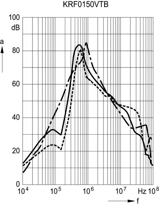
23 (120 A) KRF0120ATB (150 A) KRF0150ATB 17

 Differential mode")
24 Insertion Loss (typical values at Z = 50 Ω) Unsymmetrical, adjacent branches terminated Common mode, all branches in parallel (asymmetrical) Differential mode (symmetrical) 18

 Differential mode")
25 Insertion Loss (typical values at Z = 50 Ω) Unsymmetrical, adjacent branches terminated Common mode, all branches in parallel (asymmetrical) Differential mode (symmetrical) 19
 Differential mode (symmetrical) 20")
26 Insertion Loss (typical values at Z = 50 Ω) Unsymmetrical, adjacent branches terminated Common mode, all branches in parallel (asymmetrical) Differential mode (symmetrical) 20
27 Section 2: 520V, CB, A EMC Filters Phase: 3 Current: 180 to 400 A Voltage: 520/300 V AC, 50/60 Hz Termination: Copper Bus Part Numbers: KRF0180ACB KRF0250ACB KRF0320ACB KRF0400ACB Construction 3-line filter Metal case Features Optimized leakage current Easy to install Very compact design Optimized for operation under full load Low weight Design complies with EN , UL 1283, CSA C22.2 No.8 UL, cul approval Applications Frequency converters for motor drives Wind farms Power supplies Terminals Busbars Marking Marking on component: Manufacturer s logo, ordering code, rated voltage, rated current, rated temperature, climatic category, date code 21
28 Typical circuit diagram Technical data and measuring conditions Rated voltage V R 520/300 V AC, 50/60 Hz Read current I R Referred to 40 C ambient temperature (180 A filter at 60 C Test voltage V test 2240 V DC, 2 s (line/line) 2690 V DC, 2 s (lines, case) 3270 V DC, 2 s (line/line) 2890 V DC, 2 s (lines/case) 1.5 I R for 3 min per hour or 2.5 I R for 30 s per hour Overload capability (thermal) 520 V AC, 50 Hz Leakage current I leak 25/100/21 (-25 C/+100 C/21 days damp heat test) Climatic category (IEC ) UL 1283; CSA C22.2 No.8 Characteristics and ordering codes V R AC V 520/300 I R A I leak R typ Approx Approvals weight TCI Number ma µω kg 500/290V < KRF0180ACB X X 250 < KRF0250ACB X X 320 < KRF0320ACB X X 400 < KRF0400ACB X X X = approval granted 1) KRF0180ACB referred to 60 C ambient temperature 22
29 Dimensional drawings (180 A, 250 A) KRF0180ACB, KRF0250ACB (320 A, 400 A) KRF0320ACB, KRF0400ACB 23

 Differential mode")
30 Insertion Loss (typical values at Z = 50 Ω) Unsymmetrical, adjacent branches terminated Common mode, all branches in parallel (asymmetrical) Differential mode (symmetrical) 24
31 Section 3: 520V, CB, 150A & A EMC Filters Phase: 3 Current: 150 A; 600 to 2500 A Voltage: 520/300 V AC, 50/60 Hz Termination: Copper Bus Part Numbers: KRF0150ACB KRF0600ACB KRF1000ACB KRF1600ACB KRF2500ACB Construction 3-line filter Metal case Features Optimized leakage current Easy to install Very compact design Optimized for operation under full load Low weight UL, cul approval Applications Frequency converters for motor drives Wind farms Power supplies Terminals Busbars Marking Marking on component: Manufacturer s logo, ordering code, rated voltage, rated current, rated temperature, climatic category, date code 25
32 Typical circuit diagram Technical data and measuring conditions Rated voltage V R Read current I R Test voltage V test Overload capability (thermal) Leakage current I leak Climatic category (IEC ) 530/310 V AC, 50/60 Hz Referred to 40 C ambient temperature 2280 V DC, 2 s (line/line) 2690 V DC, 2 s (lines, case) 1.5 I R for 3 min per hour or 2.5 I R for 30 s per hour At V R, 50 Hz 25/100/21 (-25 C/+100 C/21 days damp heat test) UL 1283; CSA C22.2 No.8 (Type: 500/290 V) Characteristics and part numbers V R AC V I R A I leak ma R typ µω Approx weight kg Part Number Approvals 500/290V 530/ < KRF0150ACB X X 600 < KRF0600ACB X X 1000 < KRF1000ACB X X 1600 < KRF1600ACB X X 2500 < KRF2500ACB X X X = approval granted 26
33 Dimensional drawings (150 A) KRF0150ACB (600 A) KRF0600ACB 27
34 (1000 A) KRF1000ACB (1600 A) KRF1600ACB 28
35 (2500 A) KRF2500ACB Insertion Loss (typical values at Z = 50 Ω) Unsymmetrical, adjacent branches terminated Common mode, all branches in parallel (asymmetrical) Differential mode (symmetrical) 29
36 30
37 Section 4: 760V, TB, A EMC Filters Phase: 3 Current: 25 to 180 A Voltage: 760/440 V AC, 50/60 Hz Termination: Terminal Block Part Numbers: KRF0025VTB KRF0036VTB KRF0050VTB KRF0080VTB KRF0120VTB KRF0150VTB KRF0180VTB Construction 3-line filter Metal case Features High insertion loss Low leakage current Easy to install Degree of protection IP 20 (IEC 60529:2001) Space saving design Design complies with IEC/EN 60939, UL 1283, CSA 22.2 No. 8 Optimized for long motor cables and operation under full load UL and cul approval Applications Frequency converters for motor drives, e.g. - elevators - pumps - traction systems - conveyor systems - HVAC systems (heating, ventilation and air conditioning) Wind farms Power supplies 31
38 Terminals Finger-safe terminal blocks Marking Marking on component: Manufacturer s logo, ordering code, rated voltage, rated current, rated temperature, climatic category, date code Typical Circuit diagram Technical data and measuring conditions Rated voltage V R 760/440 V AC Rated frequency f R 50/60 Hz Test voltage line to line for 2 s V test 3270 V DC Test voltage line to case for 2 s V test 3000 V DC Rated temperature T R 40 C Overload capability (thermal) for 3 min per hour or for 30 s per hour 1.5 x I R 2.5 x I R Leakage current I leak At 690 V AC, 50 Hz Climatic category (IEC ) 25/100/21 32
39 Characteristics and part numbers I R Terminal cross section mm 2 I leak R typ Approx weight kg Part Number Approvals A ma µω 600/350V < KRF0025VTB - X X < KRF0036VTB - X X < KRF0050VTB - X X < KRF0080VTB - X X < KRF0120VTB - X X < KRF0150VTB - X X < KRF0180VTB - X X X = approval granted 33
40 Dimensional drawings (25 A, 50 A) KRF0025VTB, KRF0050VTB (80 A) KRF0080VTB 34
41 (120 A, 150 A) KRF0120VTB, KRF0150VTB (180 A) KRF0180VTB 35
")

")
42 Insertion Loss (typical values at Z = 50 Ω) Unsymmetrical, adjacent branches terminated Common mode, all branches in parallel (asymmetrical) Differential mode (symmetrical) 36

43 37
44 Section 5: 760V, CB, A EMC Filters Phase: 3 Current: 150 to 2500 A Voltage: 760/440 V AC, 50/60 Hz Termination: Copper Bus Part Numbers: KRF0150VCB KRF0180VCB KRF0250VCB KRF0320VCB KRF0400VCB KRF0600VCB KRF1000VCB KRF1600VCB KRF2500VCB Construction 3-line filter Metal case Features Optimized leakage current Easy to install Very compact design Optimized for operation under full load Low weight UL, cul approval Applications Frequency converters for motor drives Wind farms Power supplies Terminals Busbars Marking Marking on component: Manufacturer s logo, ordering code, rated voltage, rated current, rated temperature, climatic category, date code Typical circuit diagram 38
45 Technical data and measuring conditions Rated voltage V R Read current I R Overload capability (thermal) Leakage current I leak Climatic category (IEC ) Type: 760/440 V AC, 50/60 Hz Referred to 40 C ambient temperature Type: 3270 V DC, 2 s (line/line) 2890 V DC, 2 s (lines/case) 1.5 I R for 3 min per hour or 2.5 I R for 30 s per hour At V R, 50 Hz 25/100/21 (-25 C/+100 C/21 days damp heat test) UL 1283; CSA C22.2 No.8 Characteristics and part numbers V R AC V I R I leak R typ Approx weight kg Part Number Approvals A ma µω 600/350V 760/ < KRF0150VCB X X 180 < KRF0180VCB X X 250 < KRF0250VCB X X 320 < KRF0320VCB X X 400 < KRF0400VCB X X 600 < KRF0600VCB X X 1000 < KRF1000VCB X X 1600 < KRF1600VCB X X 2500 < KRF2500VCB X X X = approval granted Dimensional drawings 39
46 (150 A, 180 A) KRF0150VCB, KRF0180VCB (250 A) KRF0250VCB (320 A, 400 A) KRF0320VCB, KRF0400VCB 40
47 (600 A) KRF0600VCB (1000 A) KRF1000VCB 41
48 (1600 A) KRF1600VCB (2500 A) KRF2500VCB 42
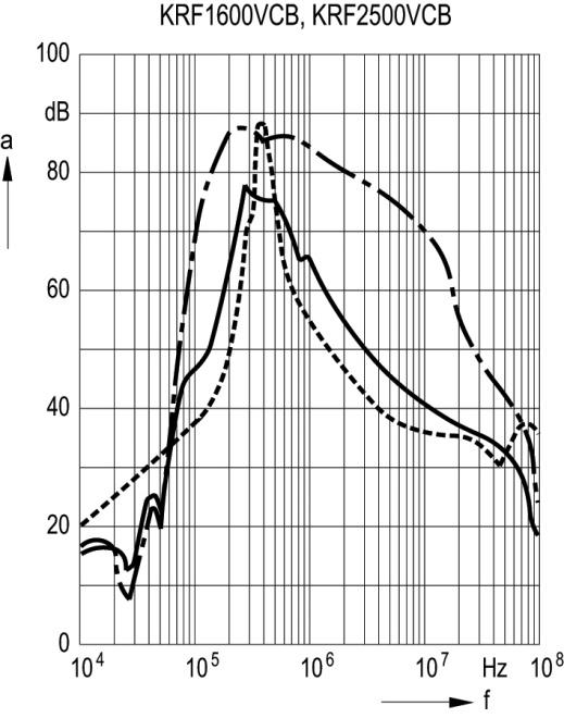
49 Insertion Loss (typical values at Z = 50 Ω) 43

 Differential mode")
50 Unsymmetrical, adjacent branches terminated Common mode, all branches in parallel (asymmetrical) Differential mode (symmetrical) 44
51 45
52 Part Number: Version /24/12 TCI, LLC W132 N10611 Grant Drive Germantown, Wisconsin Phone: Fax: Helpline: 800-TCI-8282 Web Site:
EMC filters. Mounting instructions. Date: January 2006
 Date: January 2006 EPCOS AG 2006. Reproduction, publication and dissemination of this data sheet and the information contained therein without EPCOS prior express consent is prohibited. EMC cannot be assured
1) The diagrams in the section Assembly notes were provided by Rittal GmbH Co. KG, Herborn and by Invensys Systems GmbH EUROTHERM, Limburg/ Lahn.
 The diagrams in the section Assembly notes were provided by Rittal GmbH Co. KG, Herborn and by Invensys Systems GmbH EUROTHERM, Limburg/ Lahn.") EMC cannot be achieved by the use of EMC filters alone. It must be considered as an integrated system and requires careful planning and preparations. Measures such as shielded motor leads, grounding and
EMC cannot be achieved by the use of EMC filters alone. It must be considered as an integrated system and requires careful planning and preparations. Measures such as shielded motor leads, grounding and
The following products presented in this data sheet are being withdrawn.
 EMC Filters Series/Type: B84142A*S002 The following products presented in this data sheet are being withdrawn. Ordering Code Substitute Product Date of Withdrawal Deadline Last Orders Last Shipments B84142A1000S018
EMC filters. 2-line filters SIFI-E for high insertion loss Rated current 3 to 10 A. Date: January 2006
 EMC filters 2-line filters Rated current to 0 Series/Type: Date: January 2006 EPCOS G 2006. Reproduction, publication and dissemination of this data sheet and the information contained therein without
EMC filters. 3-line filters for converters and power electronics Rated current 8 to 80 A. Date: January 2006
 EMC ilters 3-line ilters Rated current 8 to 80 A Series/Type: Date: January 2006 EPCOS AG 2006. Reproduction, publication and dissemination o this data sheet and the inormation contained therein without
2 line filters for converters and power electronics
 1000 V DC, 180... 1600 A, 40 C Ordering code: Date: 2009 10 26 Version: 2 EPCOS AG 2008. Reproduction, publication and dissemination of this publication, enclosures hereto and the information contained
The following products presented in this data sheet are being withdrawn.
 EMC Filters Series/Type: 8 The following products presented in this data sheet are being withdrawn. Ordering Code Substitute Product Date of Withdrawal Deadline ast Orders ast Shipments 800000 3-0- 3-07-3
3 line sine wave EMC output filters for converters and power electronics
 690 VAC, 95A, 180 A, 320A, 40 C Ordering code: Date: 2008 02 04 Version: 01 EPCOS AG 2008. Reproduction, publication and dissemination of this data sheet, enclosures hereto and the information contained
EMC Feedthrough Capacitors
 EMC Feedthrough Capacitors Series/Type: B85121 The following products presented in this data sheet are being withdrawn. Ordering Code Substitute Product Date of Withdrawal Deadline Last Orders Last Shipments
B84143G/Q*R/S176. Date. Function. Please send back to EPCOS MAG PEMC or to your EPCOS sales representative
 Datasheet 3-line LCL-filters 305/530 V, 50/60 Hz, 801140 A, 50 C Ordering code: Date: 2015-12-15 Version: 07 Customer release Company Date Name Function Signature Please send back to EPCOS MAG MC or to
2 line filters SIFI F for normal insertion loss
 SIFI F or normal insertion loss 25 V DC/AC, 5/ Hz, 3... 36 A Series/Type: Date: 8 8 7 Version: 7 EPCOS AG 8. Reproduction, publication and dissemination o this publication, enclosures hereto and the inormation
EMC filters. 3-line filters for converters and power electronics. Date: May 2012
 EMC filters 3-line filters Series/Type: Date: May 2012 EPCOS AG 2015. Reproduction, publication and dissemination of this publication, enclosures hereto and the information contained therein without EPCOS'
Filter for 10 Mbit data lines with HEMP-Protection according to MIL-STD
 according to MIL-STD 188-125-1 Series/Type: Date: September 2017 EPCOS AG 2017. Reproduction, publication and dissemination of this publication, enclosures hereto and the information contained therein
Power line chokes. Current-compensated D core double chokes 250 V AC, A, mh. Series/Type: B82731M/H Date: March 2008
 50 V AC, 0.5 1.8 A,. 100 mh Series/Type: B871M/H Date: March 008 Data Sheet EPCOS AG 008. Reproduction, publication and dissemination of this publication and the information contained therein without EPCOS
Power line chokes. Current-compensated frame core double chokes 250 V AC, A, mh, +40 C. Series/Type: B82733F Date: March 2011
 250 V AC, 0.7 2.3 A, 10 100 mh, +40 C Series/Type: B82733F Date: March 2011 a~í~=püééí EPCOS AG 2011. Reproduction, publication and dissemination of this publication, enclosures hereto and the information
Current-compensated frame core double chokes 250 V AC, A, mh, +40 C
 250 V AC, 0.45 1.6 A, 10 100 mh, +40 C Series/Type: B82732F Date: June 2013 a~í~=püééí EPCOS AG 2015. Reproduction, publication and dissemination of this publication, enclosures hereto and the information
Power line chokes. Current-compensated U core double chokes 300 V AC, A, mh, +40 C. Series/Type: B82730U/G Date: July 2012
 300 V AC, 0.4 2.6 A, 0.33 15 mh, +40 C Series/Type: Date: July 2012 a~í~=püééí EPCOS AG 2015. Reproduction, publication and dissemination of this publication, enclosures hereto and the information contained
%BUB4IFFU. Chokes and inductors. For high frequency and EMC RF chokes, SBC series. Series/Type: B82141A / B82141B Date: November 2005
 Chokes and inductors For high frequency and EMC RF chokes, Series/Type: / Date: November 2005 %BUB4IFFU EPCOS AG 2005. Reproduction, publication and dissemination of this publication and the information
Power line chokes. Current-compensated ring core triple chokes 440/250 V AC, 12 A, 0.35 mh. Series/Type: B82745S6123N002 Date: July 2012
 440/250 V AC, 12 A, 0.35 mh Series/Type: Date: July 2012 a~í~=püééí EPCOS AG 2015. Reproduction, publication and dissemination of this publication, enclosures hereto and the information contained therein
Filters for shielded rooms
 Series/Type: Date: September 2017 EPCOS AG 2017. Reproduction, publication and dissemination of this publication, enclosures hereto and the information contained therein without EPCOS prior express consent
EMC filters. Date: March 2012
 EMC filters Series/Type: Date: March 2012 EPCOS AG 2015. Reproduction, publication and dissemination of this publication, enclosures hereto and the information contained therein without EPCOS' prior express
Power line chokes. Current-compensated ring core double chokes 250 V AC, A, 1 82 mh. Series/Type: B82724A/J Date: July 2012
 250 V AC, 0.5 6 A, 1 82 mh Series/Type: Date: July 2012 a~í~=püééí EPCOS AG 2015. Reproduction, publication and dissemination of this publication, enclosures hereto and the information contained therein
Film Capacitors Power Factor Correction
 Series/Type: Ordering code: Date: March 2010 Version: 1 entered in headers and footers! Please fill in the Film Capacitors Power Factor Correction (if necessary) Film PC PM PFC EPCOS AG 2015. Reproduction,
EMC filters. 3-line filters for converters and power electronics. Date: May 2014
 EMC filters 3-line filters Series/Type: Date: May 2014 EPCOS AG 2015. Reproduction, publication and dissemination of this publication, enclosures hereto and the information contained therein without EPCOS'
Data and signal line chokes
 .7.7 mh, 3 6 ma, 6 C Series/Type: Date: April 28 %BUBIFFU EPCOS AG 215. Reproduction, publication and dissemination of this publication, enclosures hereto and the information contained therein without
Power Quality Solutions
 Series/Type: Ordering code: Date: July 2018 Version: 3 Content of header bars 1 and 2 of data sheet will be automatically entered in headers and footers! Please fill in the table and then change the color
Data and signal line chokes
 2.2 47 mh, 100 ma, +60 C Series/Type: B82791G15/H15 Date: October 2008, October 2011 a~í~=püééí EPCOS AG 2015. Reproduction, publication and dissemination of this publication, enclosures hereto and the
Current-compensated ring core double chokes 250 V AC, mh, A, +70 C / +80 C
 250 V AC, 0.5 6.8 mh, 4.3 10 A, +70 C / +80 C Series/Type: Date: July 2015 a~í~=püééí EPCOS AG 2015. Reproduction, publication and dissemination of this publication, enclosures hereto and the information
Manual. MOVITRAC LTE-B/LTP-B Accessories Braking Resistors, Filters, Chokes, Shielding * _0515*
 rive Technology \ rive Automation \ System Integration \ Services *21302197_0515* Manual MOVITRAC LTE-B/LTP-B Accessories Braking Resistors, Filters, Chokes, Shielding Edition 05/2015 21302197/EN SEW-EURORIVE
Current-compensated frame core double chokes 300 V AC, A, mh, +40 C
 300 V AC, 0.7 2.3 A, 10 100 mh, +40 C Series/Type: B82733F/V Date: November 2018 a~í~=püééí TDK Electronics AG 2018. Reproduction, publication and dissemination of this publication, enclosures hereto and
EMC filters. 2-line filters for converters and power electronics. Date: May 2014
 EMC filters 2-line filters Series/Type: Date: May 2014 EPCOS AG 2014. Reproduction, publication and dissemination of this publication, enclosures hereto and the information contained therein without EPCOS'
Power line chokes. Current-compensated frame core double chokes 300 V AC, A, mh, +40 C. Series/Type: B82733F/V Date: May 2015
 300 V AC, 0.7 2.3 A, 10 100 mh, +40 C Series/Type: Date: May 2015 a~í~=püééí EPCOS AG 2015. Reproduction, publication and dissemination of this publication, enclosures hereto and the information contained
Inductors. VHF chokes. Date: June 2012
 Inductors VHF chokes Series/Type: Data Sheet Date: June 2012 EPCOS AG 2015. Reproduction, publication and dissemination of this publication, enclosures hereto and the information contained therein without
EMC filters. 3-line filters for converters and power electronics. Series/Type: B84143A*R107 Date: March 2017
 EMC filters 3-line filters Series/Type: Date: March 2017 EPCOS AG 2017. Reproduction, publication and dissemination of this publication, enclosures hereto and the information contained therein without
Aluminum electrolytic capacitors
 Aluminum electrolytic capacitors Large-size capacitors Series/Type: B41605 Date: December 2006 EPCOS AG 2007. Reproduction, publication and dissemination of this publication, enclosures hereto and the
Inductors. VHF chokes B82131, B82132, B82133, B Date: June 2012
 Inductors VHF chokes Series/Type: Date: June 2012 Data Sheet B82131, B82132, B82133, B82134 EPCOS AG 2015. Reproduction, publication and dissemination of this publication, enclosures hereto and the information
Film Capacitors Power Factor Correction
 Series/Type: Ordering code: Date: July 2011 Version: 1 Content of header bars 1 and 2 of data sheet will be automatically entered in headers and footers! Please fill in the table and then change the color
Current-compensated ring core double chokes 250 V AC, mh, A, +40 C / +50 C / +60 C
 250 V AC, 0.8 100 mh, 0.5 6 A, +40 C / +50 C / +60 C Series/Type: Date: October 2016 a~í~=püééí EPCOS AG 2016. Reproduction, publication and dissemination of this publication, enclosures hereto and the
EMC filters. Date: November 2012
 EMC filters Series/Type: Date: November 2012 EPCOS AG 2012. Reproduction, publication and dissemination of this publication, enclosures hereto and the information contained therein without EPCOS' prior
EMC filters. 3-line filters for converters and power electronics. Series/Type: B84143B*S020/S021/S024 Date: May 2017
 EMC filters 3-line filters Series/Type: Date: May 2017 EPCOS AG 2017. Reproduction, publication and dissemination of this publication, enclosures hereto and the information contained therein without EPCOS'
EMC filters. 3-line filters for regenerative converters. Date: May 2014
 EMC filters 3-line filters Series/Type: Date: May 2014 EPCOS AG 2015. Reproduction, publication and dissemination of this publication, enclosures hereto and the information contained therein without EPCOS'
Data and signal line chokes
 42 V AC/8 V DC, 11 μh, 15 3 ma Series/Type: B82789C/S Date: October 28 %BUB4IFFU EPCOS AG 28. Reproduction, publication and dissemination of this publication, enclosures hereto and the information contained
Film Capacitors AC Capacitors
 Series/Type: Ordering code: Date: Jan 2012 Version: 5 Content of header bars 1 and 2 of data sheet will be automatically entered in headers and footers! Please fill in the table and then change the color
120/240 Watt AC-DC Front End with PFC W Series Convert Select 120 Convert Select 240
 Industrial Environment AC-DC Converters >100 Watt W Series 120/240 Watt AC-DC Front End with PFC W Series Convert Select 120 Convert Select 240 Rugged 35 mm DIN-rail snap-fit design 3000 V AC input to
EMC filters. 3-line filters for converters and power electronics. Series/Type: B84143A*166 Date: October 2017
 EMC filters 3-line filters Series/Type: Date: October 2017 EPCOS AG 2017. Reproduction, publication and dissemination of this publication, enclosures hereto and the information contained therein without
SMT power inductors. Size (mm) Date: March 2008
 Date: March 2008") Series/Type: Data Sheet Date: March 2008 EPCOS AG 2008. Reproduction, publication and dissemination of this publication, enclosures hereto and the information contained therein without EPCOS prior express
Series/Type: Data Sheet Date: March 2008 EPCOS AG 2008. Reproduction, publication and dissemination of this publication, enclosures hereto and the information contained therein without EPCOS prior express
Film Capacitors AC Capacitors
 Series/Type: Ordering code: Date: Jan 2012 Version: 8 Content of header bars 1 and 2 of data sheet will be automatically entered in headers and footers! Please fill in the table and then change the color
Inductors. RF chokes, HBC series. Date: March 2008
 Inductors RF chokes, HBC series Series/Type: Date: March 2008 EPCOS AG 2008. Reproduction, publication and dissemination of this publication, enclosures hereto and the information contained therein without
Inductors. RF chokes, BC series. Date: March 2008
 Inductors RF chokes, BC series Series/Type: %BUB4IFFU Date: March 2008 EPCOS AG 2008. Reproduction, publication and dissemination of this publication, enclosures hereto and the information contained therein
Power line chokes. Current-compensated D core double chokes 250 V AC, mh, A, +40 C. Series/Type: B82731M/H Date: December 2016
 250 V AC, 3.3 100 mh, 0.35 1.8 A, +40 C Series/Type: Date: December 2016 a~í~=püééí EPCOS AG 2016. Reproduction, publication and dissemination of this publication, enclosures hereto and the information
EMC filters. 4-line filters for converters and power electronics. Date: May 2014
 EMC filters 4-line filters Series/Type: Date: May 2014 EPCOS AG 2015. Reproduction, publication and dissemination of this publication, enclosures hereto and the information contained therein without EPCOS'
Film Capacitors. Metallized Polyester Film Capacitors (MKT) Date: August 2004
 Date: August 2004") Film Capacitors Metallized Polyester Film Capacitors (MKT) Series/Type: B32560... B32564 Date: August 2004 EPCOS AG 2005. Reproduction, publication and dissemination of this publication, enclosures hereto
Film Capacitors Metallized Polyester Film Capacitors (MKT) Series/Type: B32560... B32564 Date: August 2004 EPCOS AG 2005. Reproduction, publication and dissemination of this publication, enclosures hereto
EMC filters. 3-line filters for converters and power electronics. Date: March 2015
 EMC filters 3-line filters Series/Type: Date: March 2015 EPCOS AG 2015. Reproduction, publication and dissemination of this publication, enclosures hereto and the information contained therein without
Film Capacitors AC Capacitors
 Series/Type: Ordering code: Date: Nov 2013 Version: 10 Content of header bars 1 and 2 of data sheet will be automatically entered in headers and footers! Please fill in the table and then change the color
Data and signal line chokes
 4.7 68 mh, 200 700 ma, 40 C Series/Type: B82720H15 Date: October 2008 %BUB4IFFU EPCOS AG 2015. Reproduction, publication and dissemination of this publication, enclosures hereto and the information contained
Inductors. RF chokes, LBC series. Date: June 2012
 Inductors RF chokes, LBC series Series/Type: a~í~=püééí Date: June 2012 EPCOS AG 2015. Reproduction, publication and dissemination of this publication, enclosures hereto and the information contained therein
Inductors. RF chokes, LBC series. Date: June 2012
 Inductors RF chokes, LBC series Series/Type: Date: June 2012 EPCOS AG 2015. Reproduction, publication and dissemination of this publication, enclosures hereto and the information contained therein without
SMT power inductors. Size (mm) Date: June 2012
 Date: June 2012") Size 7.3 7.3 4.5 (mm) Series/Type: Data Sheet Date: June 2012 EPCOS AG 2015. Reproduction, publication and dissemination of this publication, enclosures hereto and the information contained therein without
Size 7.3 7.3 4.5 (mm) Series/Type: Data Sheet Date: June 2012 EPCOS AG 2015. Reproduction, publication and dissemination of this publication, enclosures hereto and the information contained therein without
QPI-AN1 GENERAL APPLICATION NOTE QPI FAMILY BUS SUPPLY QPI CONVERTER
 QPI-AN1 GENERAL APPLICATION NOTE QPI FAMILY EMI control is a complex design task that is highly dependent on many design elements. Like passive filters, active filters for conducted noise require careful
EDBEMV!PZi. Ä!PZiä. Electromagnetic compatibility. Global Drive Basic information on controller applications in plants and machinery
 EDBEMV!PZi Ä!PZiä L Electromagnetic compatibility Global Drive Basic information on controller applications in plants and machinery 2003 Lenze Drive Systems GmbH Without written approval of Lenze Drive
Data and signal line chokes
 0.005 4.7 mh, 200 1000 ma, +60 C Series/Type: Date: January 2017 a~í~=püééí EPCOS AG 2017. Reproduction, publication and dissemination of this publication, enclosures hereto and the information contained
Installation and Operational Instructions for ROBA -switch Type 017._00.2
 OBA -switch Type 017._00.2 Guidelines on the Declaration of Conformity A conformity evaluation has been carried out for the product in terms of the EC Low Voltage Directive 2014/35/ EC and the EMC Directive
Power line chokes. 3.4 µh / 1 MHz, 25 A, +110 C. Ordering code: B82116B2828A010. Date: Version: 01
 Power line chokes 3.4 µh / 1 MHz, 25 A, +110 C Ordering code: Date: 2016-07-07 Version: 01 EPCOS AG 2016. Reproduction, publication and dissemination of this publication, enclosures hereto and the information
B7839 B39162-B7839-K410 Nov 16,
 SAW Rx Filter GPS Series/Type: Ordering code: Date: Version: B39162--K410 Nov 16, 2005 2.1 EPCOS AG 2005. Reproduction, publication and dissemination of this data sheet, enclosures hereto and the information
SMT power inductors. Size (mm) Date: March 2008
 Date: March 2008") Size 12.95 9.4 5.08 (mm) Series/Type: %BUB4IFFU Date: March 2008 EPCOS AG 2008. Reproduction, publication and dissemination of this publication, enclosures hereto and the information contained therein
Size 12.95 9.4 5.08 (mm) Series/Type: %BUB4IFFU Date: March 2008 EPCOS AG 2008. Reproduction, publication and dissemination of this publication, enclosures hereto and the information contained therein
QUINT-PS/ 3AC/24DC/10
 Primary-switched power supply with SFB technology, 3 AC, output current 10 A INTERFACE Data sheet 103131_en_01 1 Description PHOENIX CONTACT - 09/2009 Features QUINT POWER power supply units Maximum system
EMC filters. 2-line filters for PCB mounting. Date: January 2015
 EMC filters 2-line filters Series/Type: Date: January 2015 EPCOS AG 2015. Reproduction, publication and dissemination of this publication, enclosures hereto and the information contained therein without
SMT power inductors. Size (mm) Date: June 2012
 Date: June 2012") Size 12.5 12.5 8.5 (mm) Series/Type: a~í~=püééí Date: June 2012 EPCOS AG 2015. Reproduction, publication and dissemination of this publication, enclosures hereto and the information contained therein without
Size 12.5 12.5 8.5 (mm) Series/Type: a~í~=püééí Date: June 2012 EPCOS AG 2015. Reproduction, publication and dissemination of this publication, enclosures hereto and the information contained therein without
QUINT-PS-24DC/24DC/10
 QUINT-PS-24/24/10 QUINT - converter, primary switched mode, input: 24 V, output: 24 V /10 A INTERFACE Data Sheet PHOENIX CONTACT - 02/2006 Description The QUINT - converter 24 V/10 A converts the voltage
EMC filters. 4-line filters for installations and systems. Date: May 2014
 EMC filters 4-line filters Series/Type: Date: May 2014 EPCOS AG 2015. Reproduction, publication and dissemination of this publication, enclosures hereto and the information contained therein without EPCOS'
MINI-PS AC/24DC/1.3
 Power supply unit INTERFACE Data sheet 102894_en_03 1 Description PHOENIX CONTACT 2015-11-17 Features MINI POWER power supplies for MCR technology In measurement and control technology (MCR), modular electronics
Operation Manual. SWF Series Switch Mode Power Supply. SANKEN ELECTRIC CO., LTD No.PAN E-01.
 Operation Manual SWF Series Switch Mode Power Supply 1 Table of Contents Safety Precautions 3 Appearance and Meaning of Safety Warnings 4 Hazard and Caution Safety Warnings 4 Introduction to SWF Series
SIMEAS-T. Operating Instructions Transducer without auxiliary power. 7KG6111 and 7KG6101. Operating Instructions
 Operating Instructions SIMEAS-T s Operating Instructions Transducer without auxiliary power for alternating current for alternating voltage for alternating voltage with expanded end range 7KG6111 and 7KG6101
Film Capacitors AC Capacitors
 Motor run capacitors Series/Type: Ordering code: Date: Version: 1 MotorCap S3 Compact, 100 C July 2017 Content of header bars 1 and 2 of data sheet will be automatically entered in headers and footers!
EMC filters. 2-line filters SIFI-B for enhanced insertion loss. Date: May 2014
 EMC filters 2-line filters Series/Type: Date: May 14 EPCOS AG 15. Reproduction, publication and dissemination of this publication, enclosures hereto and the information contained therein without EPCOS'
B82462G2*
 Series/Type: The following products presented in this data sheet are being withdrawn. Ordering Code Substitute Product Date of Withdrawal Deadline Last Orders Last Shipments * 2012-03-16 2012-09-28 2013-03-29
Inductors. RF chokes, LBC series, mm. Date: June 2011 Version:
 Series/Type: Date: Version: Content of header bars 1 and 2 of data sheet will be automatically entered in headers and footers! Please fill in the table and then change the color to "white". This ensures
Installation and Operational Instructions for ROBA -multiswitch Type 019._00.2
 Guidelines on the Declaration of Conformity A conformity evaluation has been carried out for the product in terms of the EU Low Voltage Directive 2014/35/ EU and the Electromagnetic Compatibility (EMC)
Data and signal line chokes
 common-mode chokes for CAN bus systems, EIA 1812 51... 100 μh, 150... 200 ma Series/Type: Date: February 2016 a~í~=püééí EPCOS AG 2016. Reproduction, publication and dissemination of this publication,
Film Capacitors AC Capacitors
 Series/Type: Ordering code: Date: 2017-08-07 Version: 2 Content of header bars 1 and 2 of data sheet will be automatically entered in headers and footers! Please fill in the table and then change the color
EMC filters. 2-line filters SIFI-H for very high insertion loss. Date: May 2014
 EMC filters 2-line filters Series/Type: Date: May 2014 EPCOS AG 2015. Reproduction, publication and dissemination of this publication, enclosures hereto and the information contained therein without EPCOS'
EMC filters. 2-line filters SIFI-G for enhanced insertion loss. Date: January 2015
 EMC filters 2-line filters Series/Type: Date: January 2015 EPCOS AG 2015. Reproduction, publication and dissemination of this publication, enclosures hereto and the information contained therein without
vacon 100 industrial vacon 100 flow vacon 100 hvac vacon 100 x ac drives du/dt filter technical guide
 vacon 100 industrial vacon 100 flow vacon 100 hvac vacon 100 x ac drives du/dt filter technical guide vacon 1 TABLE OF CONTENTS Document code: DPD01929A Date: 12.1.2017 1. Introduction... 2 1.1 Intended
Inductors. VHF chokes B82114 MAG IN PD
 Series/Type: Date: March 2010 Version: 2 Content of header bars 1 and 2 of data sheet will be automatically entered in headers and footers! Please fill in the table and then change the color to "white".
Surge arrester. 3-electrode arrester B88069X6731T702 T30-A230XSMD
 Series/Type: Ordering code: ersion/date: Issue 01 / 2007-04-26 ersion: 01 Content of header bars 1 and 2 of data sheet will be automatically entered in headers and footers! Please fill in the table and
Cable Solutions for Servo and Variable Frequency Drives (VFD)
") Cable Solutions for Servo and Variable Frequency Drives (VFD) Electric drive systems with continuous torque and speed control are widespread today. They allow an optimal adjustment of the drive with respect
Cable Solutions for Servo and Variable Frequency Drives (VFD) Electric drive systems with continuous torque and speed control are widespread today. They allow an optimal adjustment of the drive with respect
High Performance Current Transducer ITL 900-T = A
 High Performance Current Transducer ITL 900-T For the electronic measurement of currents: DC, AC, pulsed..., with galvanic separation between the primary and the secondary circuit. I PM = 0... 900 A Electrical
QUINT-PS AC/24DC/40
 Power supply unit INTERFACE Data sheet 102315_en_02 1 Description PHOENIX CONTACT 2010-04-23 Features QUINT POWER power supply units for plant and special engineering reliably start heavy loads with high
EMC filters. 2-line filters for converters and power electronics. Date: May 2014
 EMC filters 2-line filters Series/Type: Date: May 2014 EPCOS AG 2015. Reproduction, publication and dissemination of this publication, enclosures hereto and the information contained therein without EPCOS'
Inductors. RF chokes, SBC series. Date: June 2012
 Inductors RF chokes, SBC series Series/Type: Data Sheet Date: June 2012 EPCOS AG 2015. Reproduction, publication and dissemination of this publication, enclosures hereto and the information contained therein
EMC filters. 3-line sine-wave EMC output filters SineFormer 520 V AC, 6 A A, 40 C. Series/Type: B84143V*R127 Date: February 2016
 EMC filters 520 V AC, 6 A... 320 A, 40 C Series/Type: Date: February 2016 EPCOS AG 2016. Reproduction, publication and dissemination of this publication, enclosures hereto and the information contained
SMT power inductors. Size (mm) Date: June 2012
 Date: June 2012") Size.4.4 4.8 (mm) Series/Type: Data Sheet Date: June 2012 EPCOS AG 2015. Reproduction, publication and dissemination of this publication, enclosures hereto and the information contained therein without
Size.4.4 4.8 (mm) Series/Type: Data Sheet Date: June 2012 EPCOS AG 2015. Reproduction, publication and dissemination of this publication, enclosures hereto and the information contained therein without
EMC filters. 3-line filters for converters and power electronics. Series/Type: B84143B*R000 Date: July 2018
 EMC filters 3-line filters Series/Type: Date: July 2018 EPCOS AG 2018. Reproduction, publication and dissemination of this publication, enclosures hereto and the information contained therein without EPCOS'
SMT power inductors. Size 12.5 x 12.5 x 8.5 mm B82477D4 MAG IN PD
 Series/Type: Ordering code: Date: June 2013 Version: Content of header bars 1 and 2 of data sheet will be automatically entered in headers and footers! Please fill in the table and then change the color
Power supply CP-T 48/20.0 Primary switch mode power supply
 Data sheet Power supply CP-T 48/20.0 Primary switch mode power supply The CP-T range of three-phase power supply units is the youngest member of ABB s power supply family. In terms of design and functionality,
DISCRETE INPUT MODULE, 16 points
 INSTRUCTION MANUAL DISCRETE INPUT MODULE, points (Modbus) RM-DA MODEL RM-DA BEFORE USE... Thank you for choosing M-System. Before use, please check contents of the package you received as outlined below.
SAW components. SAW RF filter Short range devices. RF360 Europe GmbH A Qualcomm TDK Joint Venture. Date: September 15, 2017 Version: 2.
 A Qualcomm TDK Joint Venture Short range devices Series/type: Ordering code: B39921U410 Date: September 15, 2017 Version: 2.4 RF360 products mentioned within this document are offered by RF360 Europe GmbH
EMC filters. 2-line filters for converters and power electronics. Series/Type: B84142A*166 Date: September 2018
 EMC filters 2-line filters Series/Type: Date: September 2018 EPCOS AG 2018. Reproduction, publication and dissemination of this publication, enclosures hereto and the information contained therein without
QUINT-PS/ 3AC/24DC/40
 Primary-switched power supply unit with SFB technology, 3 AC, output current 40 A INTERFACE Data sheet 103133_en_00 1 Description PHOENIX CONTACT - 07/2009 Features QUINT POWER power supply units Maximum
Type: DILM80(110V50HZ,120V60HZ) Article No.: Sales text Contactor,37kW/400V,AC operated. Ordering information
 Article No.: Sales text Contactor,37kW/400V,AC operated. Ordering information") Type: DILM80(110V50HZ,120V60HZ) Article No.: 239399 Sales text Contactor,37kW/400V,AC operated Ordering information Connection technique Description Description Rated operational current AC 3 380 V 400
Type: DILM80(110V50HZ,120V60HZ) Article No.: 239399 Sales text Contactor,37kW/400V,AC operated Ordering information Connection technique Description Description Rated operational current AC 3 380 V 400