Implementation of a Temperature Control System using ARDUINO
|
|
|
- Lee Neal
- 5 years ago
- Views:
Transcription
1 1. Implementation of a Temperature Control System using ARDUINO
2 System structure Close control loop Fuzzy controller Fuzzy logic system: 9 rules Temperature Sensor One Wire Digital Temperature Sensor - DS18B20 Heating element Heating resistor 2Ω, supplied in ac (12V peak value) Heating power control Phase control of a SCR (thyristor) TCA 785
3 System implementation Arduino development board Brain of the entire system Read current temperature Compute error and change-of-error Run fuzzy logic system Determine digital value of control signal DAC - MCP4725, I 2 C interface Provide analog value of control signal Phase control board Analog amplifier for control voltage AD820 TCA 785 phase control IC

4 Block diagram
5 5 Computational Intelligence in Complex Decision Systems Functional diagram u(k) = u(k-1) - du c (k)

6 6 Computational Intelligence in Complex Decision Systems ARDUINO UNO development board

7 7 Programmable Resolution 1-Wire Digital Temperature Sensor 9-bit to 12-bit Celsius temperature measurements Unique 1-Wire Interface Requires Only One Port Pin for Communication Allows multiple DS18B20s to function on the same 1-Wire bus
 Rail-to-Rail Output Single-Supply Operation: 2.7V to 5.")
8 8 Computational Intelligence in Complex Decision Systems DAC MCP Bit Resolution On-Board Non-Volatile Memory (EEPROM) External Voltage Reference (VDD) Rail-to-Rail Output Single-Supply Operation: 2.7V to 5.5V I 2 C Interface Eight Available Addresses

9 9 Phase control TCA 785 Control thyristors, triacs, and transistors. The trigger pulses can be shifted within a phase angle between 0 and 180
10 1 0 TCA 785


11 1 1 Computational Intelligence in Complex Decision Systems Thermal enclosure Phase control board

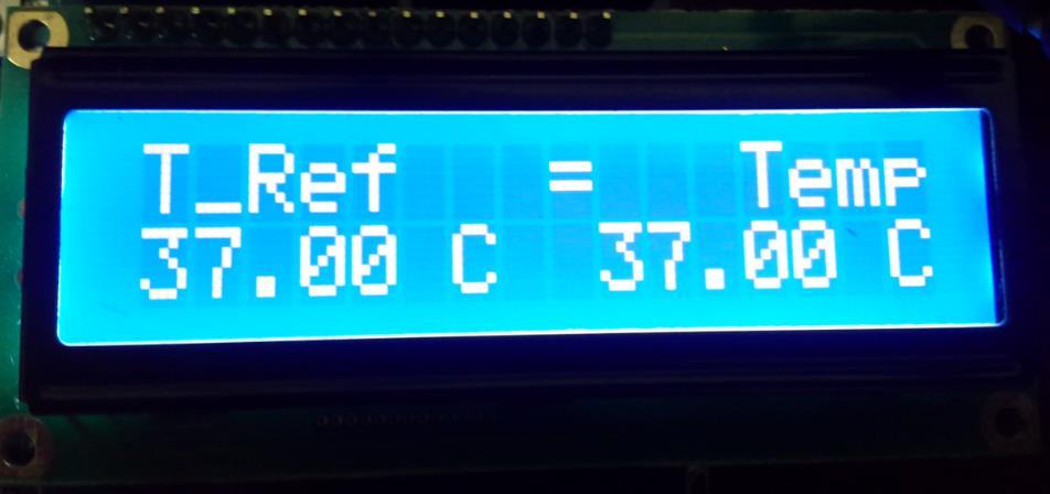
12 x 2 LCD
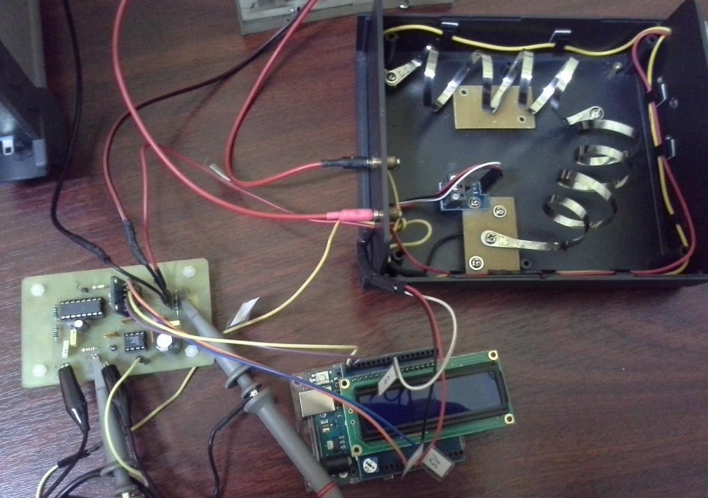
13 1 3 Experimental setup
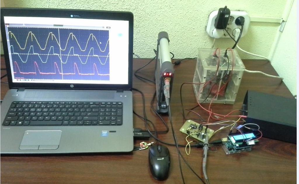
14 1 4 Experimental setup

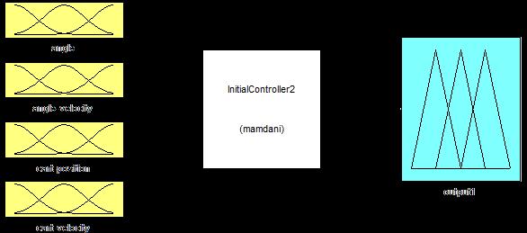
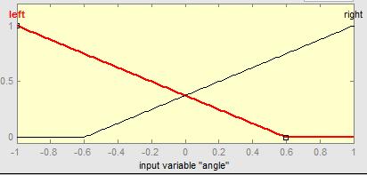
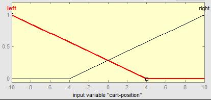
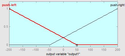
15 1 5 Computational Intelligence in Complex Decision Systems Fuzzy logic system
16 Neg Zero Pos Input fuzzy sets err; cerr Output fuzzy sets N Z P du

17 Rule base errfls cerrfls Neg Zero Pos Neg N N Z 1 Zero N Z P 2 Pos Z P P Control surface
;")
18 Waveforms for the phase control circuit CH3 - the analog control voltage applied at pin 11 of the TCA785 IC, 4.8V CH2 - the ramp voltage, generated by the TCA785 IC, at pin 10 CH1 - the positive voltage pulse generated by the TCA785 at pin 15, to be applied in the gate of the SCR to set it on (ch1, yellow); the voltage pulse is generated when the ramp voltage exceeds the analog control voltage CH4 - the almost sinusoidal supply voltage, in the secondary of the line transformer; the moment when the SCR switches on (when the positive pulse appears in its gate) is obvious on the waveform the voltage decreases due to the large current ensured through the 2Ω heating resistor Computational Intelligence in Complex Decision Systems

19 1 9 Waveforms for the power circuit Computational Intelligence in Complex Decision Systems CH1 - the supply voltage, in the secondary of the line transformer CH2 - the voltage drop across the SCR MATH - the voltage drop across the heating resistor
20 2 0 Experimental results, Tref = 45 o C Tref T temperature [C] process perturbation: opening the thermal enclosure time [s]
21 2 1 Experimental results, Tref = 45 o C 60 temp err cerr du u
22 Experimental results, Tref = 45 o C 60 temp du u 2000 contr. voltage
23 Experimental results, Tref = 37 o C Computational Intelligence in Complex Decision Systems 38 temperature [C] Tref T time [s]
24 Experimental results, Tref = 34 o C from 37 o C Tref T 36 temperature [C] time [s]
25 Experimental results, Tref = 34 o C from 37 o C 40 temp du u contr. voltage
26 2. IMPLEMENTAREA UNUI SISTEM DE CONTROL AL TEMPERATURII UTILIZÂND MATLAB
27 Fundamentare teoretică Controler fuzzy reguli definite de utilizator fiecărei reguli îi corespunde o mulţime parţială de ieşire e = e(k) - e(k-1) e y * y y * + y - e e Controler fuzzy u c Element de ieşire control Întârziere t senzor
28 Implementare practică Schema de principiu Flux achiziţie Senzor Execuţie Prelucrare analogică pentru achiziţie Prelucrare analogică pentru comandă CAN CNA Controler fuzzy Incinta termică Platforma EEboard Placa de sunet MATLAB/ Simulink Flux comandă Placă de sunet - limitare cuplaj capacitiv valori tensiune: [-1V; +1V] - amplificare achiziţie 3:1 comandă 1:1 Computational Intelligence in Complex Decision Systems
29 Senzor de temperatura Incinta termică LM35 factor de scală liniar +10 mv/ C (ex. 30 C 300mV) măsurarea temperaturii în intervalul -55 C,+125 C temperatura citită - diferită cu 0.01 C de temperatura suprafeţei precizie 0.5 C (la +25 C ) tensiune de alimentare - între 4V şi 30V Rezistenţă termică Implementare practică două rezistenţe ceramice conectate în paralel P max U 2 R ech iv
30 Implementare Platforma Electronic Explorer Flux de achiziţie Conversie cc ca Vcc Vcc 0 9 Vee 0-9 GND Vcc LM35 Vcc GND OUT GND Senzor de temperatură 0 3k Vcc V+ + LM741 OUT - Vee V- 11k 1k 0 VCC Vcc TRIGGER RESET OUTPUT CONTROL THRESHOLD Vcc DISCHARGE LM555 GND 1k GND 1k 2.2u + LM741 - V+ Vcc OUT Vee V- 1k 47n 0 1k Amplificator Av=12 Computational Intelligence in Complex Decision Systems Repetor (buffer) 0
31 Implementare cont. Flux de comandă Vcc Vee Vsursa + V+ Vcc D Vcc Vsursa Tranzistor Darlington LM741 OUT - Vee V- 10u 27k + V+ LM741 OUT - Vee V- Q1 2N2221 Q2 5.5k BD k 0 Detector de vârf pozitiv Amplificator Av = 6.5 Rezistenţa de încălzire 6,8 6.8k k
32 Implementare Schemă Simulink

33 Controler fuzzy T-S Variabile de intrare: e, de 3 mulţimi de tip zmf, gauss, smf Variabila de ieşire: du 3 mulţimi singleton: Ne = -0.2 Ze = 0 Po = 0.2 Baza de reguli e de N Z P N Ne Ne Ze Z Ne Ze Po P Ze Po Po Computational Intelligence in Complex Decision Systems
 şi (de este Z) atunci (du este Po) Defuzzificare - medie ponderată y * z 5 z 5 5 8 8")
34 Exemplu de activare a regulilor Reguli activate 5: Dacă (e este Z) şi (de este Z) atunci (du este Ze) 8: Dacă (e este P) şi (de este Z) atunci (du este Po) Defuzzificare - medie ponderată y * z 5 z

35 Rezultate experimentale Flux de achiziţie Semnalul preluat de la senzor Semnalul preluat de la 555 Semnalul transmis spre Simulink

36 Rezultate experimentale Flux de comandă Semnalul de la iesirea detectorului de vârf Semnalul provenit din Simulink
37 Rezultate experimentale Evoluţia temperaturii incintei:tref=45 C Computational Intelligence in Complex Decision Systems
38 Rezultate experimentale Evoluţia semnalelor: Tref = 45 C T e u c u cmax e 0 du c u c e, du, u c c const.
39 Rezultate experimentale Evoluţia temperaturii incintei:tref-variabilă 45 C 37 C
40 3. Implementation of a Fuzzy Logic-Based Embedded System for Engine RPM Control
41 Introduction implements an embedded system for the Engine RPM control based on a development board developed around an Arduino Mega board fuzzy logic system as controller offers an easy understanding of the main concepts regarding embedded systems Computational Intelligence in Complex Decision Systems
42 System implementation Block diagram

43 DC-Motor: Gear ratio: 30:1 Free run speed at 6V: 1000RPM Free run current at 6V: 120mA Stall current at 6V: 1600mA


44 Quadrature Encoder: Six pole magnetic disk +PCB Dual Channel 12 counts/revolution 2.8V -18V Output signal of the encoder

45 Motor Driver: L298 Middle class 2 Motors Sensors power supply


46 Arduino Mega Pinout LCD screen
47 The Arduino Mega board is the brain of the entire system. It is primarily responsible for the update of the digital control signal u, at every time instance. Therefore, the actual RPM, RPM k is read and the actual RPM error (err k ) and change of RPM error (cerr k ) are updated, as follows: (1) where is the RPM error in the previous time instance. The star of the entire system is the fuzzy logic controller, whose role is to infer the best modification in the control signal, in every time instance. The operation of the fuzzy logic controller is explained later on. The digital version of the actual control signal is updated using the relation: (2)

48 To obtain the actual RPM: Compute RPM a method based on a fixed time interval (time window) to count the revolutions of the main motor shaft. a counter is triggered at the initial time t i and it counts the pulses received from the Hall effect sensor up to the final increment t f. The RPM is computed using the relation : C f - final value of the counter C i - initial value of the counter C r = 12, number of counts/revolution G r = 30, the gear ratio (30:1) t f, t i are measured in seconds Computational Intelligence in Complex Decision Systems


49 first-order Takagi-Sugeno two inputs errfls and cerrfls one output ΔuFls The Fuzzy Logic Controller Fuzzy sets for the inputs Fuzzy sets for the output Computational Intelligence in Complex Decision Systems

50 Block diagram of the fuzzy logic controller errfls cerrfls Neg Zero Pos Neg N N Z Zero N Z P Pos Z P P Rule base of the fuzzy logic system
51 The defuzzification method, used to transform the partial output fuzzy sets resulted from the inference process into a crisp value is the weighted average method.

52 output Computational Intelligence in Complex Decision Systems Control surface of the fuzzy logic controller Err cerr
53 Control Circuit RPM ref + _ RPM err 1 z _ + cerr s e s c errfls cerrfls Fuzzy logic system ΔuFls s u Δu z 255 u Motor Driver u a DC Motor

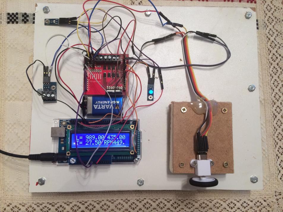
54 System setup
55 Experimental results RPM from 0 to 1000 rise time = 8.8 s; max. positive error = 5 rpm ; max. negative error = 5rpm; RPM from 1000 to 500 fall time = 6.75 s; max. positive error = 6 rpm ; max. negative error = 9rpm; RPM from 500 to 750 rise time = 4.75 s; max. positive error = 8 rpm ; max. negative error = 6rpm; RPM from 750 to 0 fall time = 6.5 s;
56
57 Decreasing the time response To drastically decrease the time response of the control system, the control strategy should be slightly modified. Because the control characteristic of the DC motor driven by the H-Bridge is almost liner, when a large variation of the motor speed is required (larger than 60 rpm), the control signal is not determined by the fuzzy logic system, but it is estimated by a simple linear interpolation, that acts as a course adjustment of the control signal. Then, the fuzzy logic system regains its role for the fine adjustment of the speed.
58

59 Tracking mode operation: RPM tracks the temperature variation Computational Intelligence in Complex Decision Systems

60 Duty Cycle 23% Low Speed 55% Medium Speed 90% High Speed
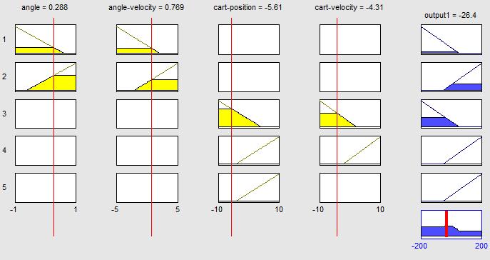
61 4. Controlul pendulului inversat
62 4. Controlul pendulului inversat demonstratie video pendul.fis

63
64
Implementation of a Fuzzy Logic-Based Embedded System for Engine RPM Control. (Speed Control)
") Implementation of a Fuzzy Logic-Based Embedded System for Engine RPM Control (Speed Control) Introduction implements an embedded system for the Engine RPM control based on a development board developed
Implementation of a Fuzzy Logic-Based Embedded System for Engine RPM Control (Speed Control) Introduction implements an embedded system for the Engine RPM control based on a development board developed
ELG3331: Digital Tachometer Introduction to Mechatronics by DG Alciatore and M B Histand
 ELG333: Digital Tachometer Introduction to Mechatronics by DG Alciatore and M B Histand Our objective is to design a system to measure and the rotational speed of a shaft. A simple method to measure rotational
SPEED CONTROL OF INDUCTION MOTOR WITHOUT SPEED SENSOR AT LOW SPEED OPERATIONS
 SPEED CONTROL OF INDUCTION MOTOR WITHOUT SPEED SENSOR AT LOW SPEED OPERATIONS Akshay Prasad Dubey and Saravana Kumar R. School of Electrical Engineering, VIT University, Vellore, Tamil Nadu, India E-Mail:
Linear Integrated Circuits
 Linear Integrated Circuits Single Slope ADC Comparator checks input voltage with integrated reference voltage, V REF At the same time the number of clock cycles is being counted. When the integrator output
Single-phase Variable Frequency Switch Gear
 Single-phase Variable Frequency Switch Gear Eric Motyl, Leslie Zeman Advisor: Professor Steven Gutschlag Department of Electrical and Computer Engineering Bradley University, Peoria, IL May 13, 2016 ABSTRACT
HAW-Arduino. Sensors and Arduino F. Schubert HAW - Arduino 1
 HAW-Arduino Sensors and Arduino 14.10.2010 F. Schubert HAW - Arduino 1 Content of the USB-Stick PDF-File of this script Arduino-software Source-codes Helpful links 14.10.2010 HAW - Arduino 2 Report for
Multiple Instrument Station Module
 Multiple Instrument Station Module Digital Storage Oscilloscope Vertical Channels Sampling rate Bandwidth Coupling Input impedance Vertical sensitivity Vertical resolution Max. input voltage Horizontal
Introduction to IC-555. Compiled By: Chanakya Bhatt EE, IT-NU
 Introduction to IC-555 Compiled By: Chanakya Bhatt EE, IT-NU Introduction SE/NE 555 is a Timer IC introduced by Signetics Corporation in 1970 s. It is basically a monolithic timing circuit that produces
TMC603EVAL MANUAL Evaluation board for the TMC603 three phase motor driver with BLDC back EMF commutation hallfx
 TMC603EVAL MANUAL Evaluation board for the TMC603 three phase motor driver with BLDC back EMF commutation hallfx TRINAMIC Motion Control GmbH & Co. KG Sternstraße 67 D 20357 Hamburg GERMANY www.trinamic.com
ECE 5670/6670 Project. Brushless DC Motor Control with 6-Step Commutation. Objectives
 ECE 5670/6670 Project Brushless DC Motor Control with 6-Step Commutation Objectives The objective of the project is to build a circuit for 6-step commutation of a brushless DC motor and to implement control
MTY (81)
") This manual describes the option "e" of the SMT-BD1 amplifier: Master/slave tension control application. The general information about the digital amplifier commissioning are described in the standard
This manual describes the option "e" of the SMT-BD1 amplifier: Master/slave tension control application. The general information about the digital amplifier commissioning are described in the standard
DC Motor and Servo motor Control with ARM and Arduino. Created by:
 DC Motor and Servo motor Control with ARM and Arduino Created by: Andrew Kaler (39345) Tucker Boyd (46434) Mohammed Chowdhury (860822) Tazwar Muttaqi (901700) Mark Murdock (98071) May 4th, 2017 Objective
AEDA-3200-Txx Series Ultra Miniature, High Resolution Incremental Encoders
 AEDA-3200-Txx Series Ultra Miniature, High Resolution Incremental Encoders Data Sheet Description The AEDA-3200-T series (top mounting type) are high performance, cost effective, three-channel optical
Application Note. Brushless DC Motor Control AN-1114
 Application Note AN-1114 Abstract In this application note a GreenPAK configuration applicable for a single-phase BLDC motor is introduced. This application note comes complete with design files which
Fuzzy Logic Temperature Control System For The Induction Furnace
 Fuzzy Logic Temperature Control System For The Induction Furnace Lei Lei Hnin, U Zaw Min Min Htun, Hla Myo Tun Abstract: This research paper describes the fuzzy logic temperature control system of the
CHAPTER 3 METHODOLOGY
 CHAPTER 3 METHODOLOGY 3.1 INTRODUCTION This chapter will explain about the flow chart of project, designing fuzzy logic controller and fuzzy logic algorithms. Next, it will explain electrical circuit design
LINEAR IC APPLICATIONS
 1 B.Tech III Year I Semester (R09) Regular & Supplementary Examinations December/January 2013/14 1 (a) Why is R e in an emitter-coupled differential amplifier replaced by a constant current source? (b)
DUAL STEPPER MOTOR DRIVER
 DUAL STEPPER MOTOR DRIVER GENERAL DESCRIPTION The is a switch-mode (chopper), constant-current driver with two channels: one for each winding of a two-phase stepper motor. is equipped with a Disable input
6. HARDWARE PROTOTYPE AND EXPERIMENTAL RESULTS
 6. HARDWARE PROTOTYPE AND EXPERIMENTAL RESULTS Laboratory based hardware prototype is developed for the z-source inverter based conversion set up in line with control system designed, simulated and discussed
CHAPTER 4 FUZZY LOGIC CONTROLLER
 62 CHAPTER 4 FUZZY LOGIC CONTROLLER 4.1 INTRODUCTION Unlike digital logic, the Fuzzy Logic is a multivalued logic. It deals with approximate perceptive rather than precise. The effective and efficient
Jaguar Motor Controller (Stellaris Brushed DC Motor Control Module with CAN)
") Jaguar Motor Controller (Stellaris Brushed DC Motor Control Module with CAN) 217-3367 Ordering Information Product Number Description 217-3367 Stellaris Brushed DC Motor Control Module with CAN (217-3367)
Jaguar Motor Controller (Stellaris Brushed DC Motor Control Module with CAN) 217-3367 Ordering Information Product Number Description 217-3367 Stellaris Brushed DC Motor Control Module with CAN (217-3367)
STEPPING MOTOR EMULATION
 OPERATING MANUAL SERIES SMTBD1 OPTIONAL FUNCTIONS (Version 2.0) European version 2.0 STEPPING MOTOR EMULATION OPTION C This manual describes the option "C" of the SMT-BD1 amplifier: Stepping motor emulation.
push-pole (2014) design / implementation /technical information
 design / implementation /technical information") push-pole (2014) design / implementation /technical information www.nolanlem.com The intention of this document is to highlight the considerations that went into the technical, spatial, temporal, and aesthetic
push-pole (2014) design / implementation /technical information www.nolanlem.com The intention of this document is to highlight the considerations that went into the technical, spatial, temporal, and aesthetic
Phase Control IC TCA 785
 Phase Control IC Bipolar IC Features Reliable recognition of zero passage Large application scope May be used as zero point switch LSL compatible Three-phase operation possible (3 ICs) Output current 250
MTY (81)
") This manual describes the option "d" of the SMT-BD1 amplifier: Master/slave electronic gearing. The general information about the digital amplifier commissioning are described in the standard SMT-BD1 manual.
This manual describes the option "d" of the SMT-BD1 amplifier: Master/slave electronic gearing. The general information about the digital amplifier commissioning are described in the standard SMT-BD1 manual.
Where: (J LM ) is the load inertia referred to the motor shaft. 8.0 CONSIDERATIONS FOR THE CONTROL OF DC MICROMOTORS. 8.
 is the load inertia referred to the motor shaft. 8.0 CONSIDERATIONS FOR THE CONTROL OF DC MICROMOTORS. 8.") Where: (J LM ) is the load inertia referred to the motor shaft. 8.0 CONSIDERATIONS FOR THE CONTROL OF DC MICROMOTORS 8.1 General Comments Due to its inherent qualities the Escap micromotor is very suitable
Where: (J LM ) is the load inertia referred to the motor shaft. 8.0 CONSIDERATIONS FOR THE CONTROL OF DC MICROMOTORS 8.1 General Comments Due to its inherent qualities the Escap micromotor is very suitable
Dedan Kimathi University of technology. Department of Electrical and Electronic Engineering. EEE2406: Instrumentation. Lab 2
 Dedan Kimathi University of technology Department of Electrical and Electronic Engineering EEE2406: Instrumentation Lab 2 Title: Analogue to Digital Conversion October 2, 2015 1 Analogue to Digital Conversion
PreLab 6 PWM Design for H-bridge Driver (due Oct 23)
") GOAL PreLab 6 PWM Design for H-bridge Driver (due Oct 23) The overall goal of Lab6 is to demonstrate a DC motor controller that can adjust speed and direction. You will design the PWM waveform and digital
GOAL PreLab 6 PWM Design for H-bridge Driver (due Oct 23) The overall goal of Lab6 is to demonstrate a DC motor controller that can adjust speed and direction. You will design the PWM waveform and digital
AVL-10000T AUDIO VIDEO LINK TRANSMITTER TECHNICAL MANUAL
 AVL-10000T AUDIO VIDEO LINK TRANSMITTER TECHNICAL MANUAL Document : AVL-10000T Version: 1.00 Author: Henry S Date: 25 July 2008 This module contains protection circuitry to guard against damage due to
Agilent AEDA-3200-Txx Series Ultra Miniature, High Resolution Incremental Encoders
 Agilent AEDA-3200-Txx Series Ultra Miniature, High Resolution Incremental Encoders Data Sheet Features Two channel quadrature output with index pulse Quick and easy assembly using Plug and Play tool Cost-effective
Tarocco Closed Loop Motor Controller
 Contents Safety Information... 3 Overview... 4 Features... 4 SoC for Closed Loop Control... 4 Gate Driver... 5 MOSFETs in H Bridge Configuration... 5 Device Characteristics... 6 Installation... 7 Motor
CHAPTER-5 DESIGN OF DIRECT TORQUE CONTROLLED INDUCTION MOTOR DRIVE
 113 CHAPTER-5 DESIGN OF DIRECT TORQUE CONTROLLED INDUCTION MOTOR DRIVE 5.1 INTRODUCTION This chapter describes hardware design and implementation of direct torque controlled induction motor drive with
Modeling, Simulation and Implementation of Speed Control of DC Motor Using PIC 16F877A
 Modeling, Simulation and Implementation of Speed Control of DC Motor Using PIC 16F877A Payal P.Raval 1, Prof.C.R.mehta 2 1 PG Student, Electrical Engg. Department, Nirma University, SG Highway, Ahmedabad,
2.017 DESIGN OF ELECTROMECHANICAL ROBOTIC SYSTEMS Fall 2009 Lab 4: Motor Control. October 5, 2009 Dr. Harrison H. Chin
 2.017 DESIGN OF ELECTROMECHANICAL ROBOTIC SYSTEMS Fall 2009 Lab 4: Motor Control October 5, 2009 Dr. Harrison H. Chin Formal Labs 1. Microcontrollers Introduction to microcontrollers Arduino microcontroller
EUP V/12V Synchronous Buck PWM Controller DESCRIPTION FEATURES APPLICATIONS. Typical Application Circuit. 1
 5V/12V Synchronous Buck PWM Controller DESCRIPTION The is a high efficiency, fixed 300kHz frequency, voltage mode, synchronous PWM controller. The device drives two low cost N-channel MOSFETs and is designed
NJM3777 DUAL STEPPER MOTOR DRIVER NJM3777E3(SOP24)
") DUAL STEPPER MOTOR DRIER GENERAL DESCRIPTION The NJM3777 is a switch-mode (chopper), constant-current driver with two channels: one for each winding of a two-phase stepper motor. The NJM3777 is equipped
DUAL STEPPER MOTOR DRIER GENERAL DESCRIPTION The NJM3777 is a switch-mode (chopper), constant-current driver with two channels: one for each winding of a two-phase stepper motor. The NJM3777 is equipped
Lab 5: Inverted Pendulum PID Control
 Lab 5: Inverted Pendulum PID Control In this lab we will be learning about PID (Proportional Integral Derivative) control and using it to keep an inverted pendulum system upright. We chose an inverted
CHAPTER ELEVEN - Interfacing With the Analog World
 CHAPTER ELEVEN - Interfacing With the Analog World 11.1 (a) Analog output = (K) x (digital input) (b) Smallest change that can occur in the analog output as a result of a change in the digital input. (c)
Evaluation Kit: MPS 160 ASIC. Magneto Encoder ASIC
 Evaluation Kit: MPS 160 ASIC Magneto Encoder ASIC Table of Contents 1. Overview 2. Mounting Instructions 2.1. Sensor Orientation 2.2. Pitch Radius 2.3. Air Gap 3. Magnetic Target 4. Output 4.1. Optional
MP V-to-16V,1.2A, Single-Phase Brushless DC Motor Driver
 MP6510 4.5V-to-16V,1.2A, Single-Phase Brushless DC Motor Driver DESCRIPTION The MP6510 is a single-phase, brushless, DC motor driver with integrated power MOSFETs. It drives single-phase brushless DC motors.
For more information on these functions and others please refer to the PRONET-E User s Manual.
 PRONET-E Quick Start Guide PRONET-E Quick Start Guide BASIC FUNCTIONS This guide will familiarize the user with the basic functions of the PRONET-E Servo Drive and assist with start up. The descriptions
National Infotech. Electrical Drive Trainers. Developed By: : Authorized Dealer : Embedded System Solutions
 National Infotech A way to Power Electronics and Embedded System Solutions Electrical Drive Trainers In every industry there are industrial processes where electrical motors are used as a part of process
Capacitive Touch Sensing Tone Generator. Corey Cleveland and Eric Ponce
 Capacitive Touch Sensing Tone Generator Corey Cleveland and Eric Ponce Table of Contents Introduction Capacitive Sensing Overview Reference Oscillator Capacitive Grid Phase Detector Signal Transformer
PowerAmp Design. PowerAmp Design PAD112 HIGH VOLTAGE OPERATIONAL AMPLIFIER
 PowerAmp Design Rev C KEY FEATURES LOW COST HIGH VOLTAGE 150 VOLTS HIGH OUTPUT CURRENT 5 AMPS 50 WATT DISSIPATION CAPABILITY 100 WATT OUTPUT CAPABILITY INTEGRATED HEAT SINK AND FAN COMPATIBLE WITH PAD123
MCP Bit, Quad Digital-to-Analog Converter with EEPROM Memory. Features. Description. Applications
 12-Bit, Quad Digital-to-Analog Converter with EEPROM Memory Features 12-Bit Voltage Output DAC with Four Buffered Outputs On-Board Nonvolatile Memory (EEPROM) for DAC Codes and I 2 C Address Bits Internal
MOBILE ROBOT LOCALIZATION with POSITION CONTROL
 T.C. DOKUZ EYLÜL UNIVERSITY ENGINEERING FACULTY ELECTRICAL & ELECTRONICS ENGINEERING DEPARTMENT MOBILE ROBOT LOCALIZATION with POSITION CONTROL Project Report by Ayhan ŞAVKLIYILDIZ - 2011502093 Burcu YELİS
EEE312: Electrical measurement & instrumentation
 University of Turkish Aeronautical Association Faculty of Engineering EEE department EEE312: Electrical measurement & instrumentation Digital Electronic meters BY Ankara March 2017 1 Introduction The digital
AN1114 APPLICATION NOTE
 AN4 APPLICATION NOTE BURST MODE TRIAC CONTROL BY USING ST52x30 Authors: A. Cucuccio, M. Lo Presti. INTRODUCTION The aim of this application note is to provide a complete hardware schematic and the software
Assembly Language. Topic 14 Motion Control. Stepper and Servo Motors
 Assembly Language Topic 14 Motion Control Stepper and Servo Motors Objectives To gain an understanding of the operation of a stepper motor To develop a means to control a stepper motor To gain an understanding
Designated client product
 Designated client product This product will be discontinued its production in the near term. And it is provided for customers currently in use only, with a time limit. It can not be available for your
Figure 1. Digilent DC Motor
 Laboratory 9 - Usage of DC- and servo-motors The current laboratory describes the usage of DC and servomotors 1. DC motors Figure 1. Digilent DC Motor Classical DC motors are converting electrical energy
PowerAmp Design. PowerAmp Design PAD117A RAIL TO RAIL OPERATIONAL AMPLIFIER
 PowerAmp Design RAIL TO RAIL OPERATIONAL AMPLIFIER Rev J KEY FEATURES LOW COST RAIL TO RAIL INPUT & OUTPUT SINGLE SUPPLY OPERATION HIGH VOLTAGE 100 VOLTS HIGH OUTPUT CURRENT 15A 250 WATT OUTPUT CAPABILITY
RX23T inverter ref. kit
 RX23T inverter ref. kit Deep Dive October 2015 YROTATE-IT-RX23T kit content Page 2 YROTATE-IT-RX23T kit: 3-ph. Brushless Motor Specs Page 3 Motors & driving methods supported Brushless DC Permanent Magnet
DIGITAL ELECTRONICS ANALOG ELECTRONICS
 DIGITAL ELECTRONICS 1. N10 4 Bit Binary Universal shift register. 2. N22- Random Access Memory (16*4). 3. N23- Read Only Memory. 4. N4-R-S/D-T Flip flop, characteristic and comparison. 5. Master Slave
Lab 9. Speed Control of a D.C. motor. Sensing Motor Speed (Tachometer Frequency Method)
") Lab 9. Speed Control of a D.C. motor Sensing Motor Speed (Tachometer Frequency Method) Motor Speed Control Project 1. Generate PWM waveform 2. Amplify the waveform to drive the motor 3. Measure motor speed
Lab 9. Speed Control of a D.C. motor Sensing Motor Speed (Tachometer Frequency Method) Motor Speed Control Project 1. Generate PWM waveform 2. Amplify the waveform to drive the motor 3. Measure motor speed
Experiment#6: Speaker Control
 Experiment#6: Speaker Control I. Objectives 1. Describe the operation of the driving circuit for SP1 speaker. II. Circuit Description The circuit of speaker and driver is shown in figure# 1 below. The
Smart motor driver with embedded Hall sensor
 Smart motor driver with embedded Hall sensor Features Motor driver with integrated Hall sensor Lock-shutdown protection & auto-restart function Precise magnetic switching thresholds Soft-switch phase-switching
SPEED CONTROL OF DC MOTOR USING PWM TECHNIQUE
 SPEED CONTROL OF DC MOTOR USING PWM TECHNIQUE Shubham Naik 1 1 Electrical Engineering Abstract DC motors are widely used in industries where high speed torque requirement. Because of it characteristics
University of North Carolina-Charlotte Department of Electrical and Computer Engineering ECGR 3157 Electrical Engineering Design II Fall 2013
 Exercise 1: PWM Modulator University of North Carolina-Charlotte Department of Electrical and Computer Engineering ECGR 3157 Electrical Engineering Design II Fall 2013 Lab 3: Power-System Components and
Brushed DC Motor Microcontroller PWM Speed Control with Optical Encoder and H-Bridge
 Brushed DC Motor Microcontroller PWM Speed Control with Optical Encoder and H-Bridge L298 Full H-Bridge HEF4071B OR Gate Brushed DC Motor with Optical Encoder & Load Inertia Flyback Diodes Arduino Microcontroller
LS7362 BRUSHLESS DC MOTOR COMMUTATOR / CONTROLLER
 LS7362 BRUSHLESS DC MOTOR COMMUTATOR / CONTROLLER FEATURES: Speed control by Pulse Width Modulating (PWM) only the low-side drivers reduces switching losses in level converter circuitry for high voltage
HIGH SPEED, 100V, SELF OSCILLATING 50% DUTY CYCLE, HALF-BRIDGE DRIVER
 Data Sheet No. 60206 HIGH SPEED, 100V, SELF OSCILLATING 50% DUTY CYCLE, HALF-BRIDGE DRIVER Features Simple primary side control solution to enable half-bridge DC-Bus Converters for 48V distributed systems
Features DIMENSIONS ARE MILLIMETERS INCHES LEAD THICKNESS: CH B CH A. Gnd VCC X 50 H97X
 HEDS-973x Series Small Optical Encoder Modules Data Sheet Description The HEDS-973x series is a high performance, low cost, optical incremental encoder module. When operated in conjunction with either
Analog-to-Digital Converter (ADC) And Digital-to-Analog Converter (DAC)
 And Digital-to-Analog Converter (DAC)") 1 Analog-to-Digital Converter (ADC) And Digital-to-Analog Converter (DAC) 2 1. DAC In an electronic circuit, a combination of high voltage (+5V) and low voltage (0V) is usually used to represent a binary
1 Analog-to-Digital Converter (ADC) And Digital-to-Analog Converter (DAC) 2 1. DAC In an electronic circuit, a combination of high voltage (+5V) and low voltage (0V) is usually used to represent a binary
CAP6637A AC-DC Open Loop Converter
 Description: The CAP6637 is a three-phase AC to DC Converter assembly. The assembly includes the three-phase SCR converter bridge, a free wheeling diode, the thermal management system, a BAP1950 SCR phase
Fig 1: The symbol for a comparator
 INTRODUCTION A comparator is a device that compares two voltages or currents and switches its output to indicate which is larger. They are commonly used in devices such as They are commonly used in devices
PowerAmp Design. PowerAmp Design PAD20 COMPACT HIGH VOLTAGE OP AMP
 PowerAmp Design Rev C KEY FEATURES LOW COST HIGH VOLTAGE 150 VOLTS HIGH OUTPUT CURRENT 5A 40 WATT DISSIPATION CAPABILITY 80 WATT OUTPUT CAPABILITY INTEGRATED HEAT SINK AND FAN SMALL SIZE 40mm SQUARE RoHS
Mini Encoder High Resolution
 Mini Encoder High Resolution PWB encoders GmbH Am Goldberg 2 D-99817 Eisenach Germany Phone: +49 3691 72580-0 Fax: +49 3691 72580-29 info@pwb-encoders.com MEHR25 plug Rev.5A / 27.04.2017 info@pwb-encoders.com
AEDR-871x. Data Sheet. 3-Channel High Resolution Reflective Incremental Encoder (Digital Outputs) Description. Features.
 Description. Features.") Data Sheet AEDR-871x 3-Channel High Resolution Reflective Incremental Encoder (Digital Outputs) Description The AEDR-871x encoder is the smallest 3-channel optical encoder with digital outputs that employs
Data Sheet AEDR-871x 3-Channel High Resolution Reflective Incremental Encoder (Digital Outputs) Description The AEDR-871x encoder is the smallest 3-channel optical encoder with digital outputs that employs
20V, 2A Buck Switching Regulator
 20V, 2A Buck Switching Regulator FP6101 General Description The FP6101 is a buck switching regulator for wide operating voltage application fields. The FP6101 includes a high current P-MOSFET, high precision
USB4. Encoder Data Acquisition USB Device Page 1 of 8. Description. Features
 USB4 Page 1 of 8 The USB4 is a data acquisition device designed to record data from 4 incremental encoders, 8 digital inputs and 4 analog input channels. In addition, the USB4 provides 8 digital outputs
NU1005/6: 5V Full Bridge Driver for High Integration, High Efficiency and Low Cost Wireless Power Transmitter
 NU1005/6: 5V Full Bridge Driver for High Integration, High Efficiency and Low Cost Wireless Power Transmitter 1 Feature Input Voltage: 4.0V to 5.5V Output Power: 2.5W (NU1005) and 5W (NU1006) Integrated
EEE3410 Microcontroller Applications Department of Electrical Engineering. Lecture 10. Analogue Interfacing. Vocational Training Council, Hong Kong.
 Department of Electrical Engineering Lecture 10 Analogue Interfacing 1 In this Lecture. Interface 8051 with the following Input/Output Devices Transducer/Sensors Analogue-to-Digital Conversion (ADC) Digital-to-Analogue
AUTOMATIC RESISTOR COLOUR CODING DETECTION & ALLOCATION
 AUTOMATIC RESISTOR COLOUR CODING DETECTION & ALLOCATION Abin Thomas 1, Arun Babu 2, Prof. Raji A 3 Electronics Engineering, College of Engineering Adoor (India) ABSTRACT In this modern world, the use of
Chapter 2 Signal Conditioning, Propagation, and Conversion
 09/0 PHY 4330 Instrumentation I Chapter Signal Conditioning, Propagation, and Conversion. Amplification (Review of Op-amps) Reference: D. A. Bell, Operational Amplifiers Applications, Troubleshooting,
BLuAC5 Brushless Universal Servo Amplifier
 BLuAC5 Brushless Universal Servo Amplifier Description The BLu Series servo drives provide compact, reliable solutions for a wide range of motion applications in a variety of industries. BLu Series drives
DC Geared Motor with Encoder MO-SPG-30E-XXXK
 DC Geared Motor with Encoder MO-SPG-30E-XXXK USER S MANUAL V1.1 May 2011 Information contained in this publication regarding device applications and the like is intended through suggestion only and may
Data Sheet. HEDL-65xx, HEDM-65xx, HEDS-65xx Series Large Diameter (56 mm), Housed Two and Three Channel Optical Encoders. Description.
, Housed Two and Three Channel Optical Encoders. Description.") HEDL-65xx, HEDM-65xx, HEDS-65xx Series Large Diameter (56 mm), Housed Two and Three Channel Optical Encoders Data Sheet Description The HEDS-65xx/HEDL-65xx are high performance two and three channel optical
HEDL-65xx, HEDM-65xx, HEDS-65xx Series Large Diameter (56 mm), Housed Two and Three Channel Optical Encoders Data Sheet Description The HEDS-65xx/HEDL-65xx are high performance two and three channel optical
3185 THRU 3189 HALL-EFFECT LATCHES FOR HIGH-TEMPERATURE OPERATION FEATURES. ABSOLUTE MAXIMUM RATINGS at T A = +25 C V CC GROUND OUTPUT SUPPLY
 3185 THRU 3189 Data Sheet 2769.2A X V CC These Hall-effect latches are extremely temperature-stable and stressresistant sensors especially suited for operation over extended temperature ranges to +15 C.
Lab 2 Revisited Exercise
 Lab 2 Revisited Exercise +15V 100k 1K 2N2222 Wire up led display Note the ground leads LED orientation 6.091 IAP 2008 Lecture 3 1 Comparator, Oscillator +5 +15 1k 2 V- 7 6 Vin 3 V+ 4 V o Notice that power
Thornwood Drive Operating Manual: Two-SCR General Purpose Gate Firing Board FCRO2100 Revision H
 http://www.enerpro-inc.com info@enerpro-inc.com 5780 Thornwood Drive Report R188 Goleta, California 93117 February 2011 Operating Manual: Two-SCR General Purpose Gate Firing Board FCRO2100 Revision H Introduction
TECHNICAL DATASHEET #TDAX ISOLATED DUAL CHANNEL UNIVERSAL SIGNAL CONVERTER
 Preliminary TECHNICAL DATASHEET TDAX130540 ISOLATED DUAL CHANNEL UNIVERSAL SIGNAL CONVERTER 2 Analog (Bipolar), Resistive, Digital, Frequency (RPM) or PWM Signal Inputs Encoder Input Magnetic Pick Up Input
MASTER/SLAVE TENSION CONTROL
 OPERATING MANUAL SERIES SMTBD1 OPTIONAL FUNCTIONS (Version 2.0) European version 2.0 MASTER/SLAVE TENSION CONTROL OPTION E This manual describes the option "E" of the SMT-BD1 amplifier: Master / Slave
TDA 4700 TDA Control IC for Single-Ended and Push-Pull Switched-Mode Power Supplies (SMPS)
") Control IC for Single-Ended and Push-Pull Switched-Mode Power Supplies (SMPS) TDA 4700 Features Feed-forward control (line hum suppression) Symmetry inputs for push-pull converter (TDA 4700) Push-pull
Control IC for Single-Ended and Push-Pull Switched-Mode Power Supplies (SMPS) TDA 4700 Features Feed-forward control (line hum suppression) Symmetry inputs for push-pull converter (TDA 4700) Push-pull
A Hybrid Particle Swarm Optimization Algorithm for Maximum Power Point Tracking of Solar Photovoltaic Systems
 Proceedings of The National Conference On Undergraduate Research (NCUR) 2017 University of Memphis Memphis, Tennessee April 6-8, 2017 A Hybrid Particle Swarm Optimization Algorithm for Maximum Power Point
Application Note. I C s f o r M o t o r C o n t r o l. Evaluation board for the TDA5143/TDA5144. Report No: EIE/AN R. Galema
 Application Note I C s f o r M o t o r C o n t r o l Evaluation board for the TDA5143/TDA5144 Report No: R. Galema Product Concept & Application Laboratory Eindhoven, the Netherlands. Keywords Motor Control
NEW DIGITAL ANGLE MEASUREMENT FACILITY BASED ON FPGA
 30 th ovember 202. Vol. 45 o.2 ISS: 992-8645 www.jatit.org E-ISS: 87-395 EW DIGITAL AGLE MEASUREMET FACILITY BASED O FPGA HAO ZHAO, 2 HAO FEG Jiaxing University, Jiaxing Zhejiang China 2 Hangzhou Dianzi
Bipolar Hall Effect Switch CYD72X
 Version 2 Released in May 2016 Dr.-Ing. habil. Jigou Liu ChenYang Bipolar Hall Effect Switch CYD72X CYD72X is a Hall sensor with latched digital output. It s suitable for electronic commutation of brushless
PIC Functionality. General I/O Dedicated Interrupt Change State Interrupt Input Capture Output Compare PWM ADC RS232
 PIC Functionality General I/O Dedicated Interrupt Change State Interrupt Input Capture Output Compare PWM ADC RS232 General I/O Logic Output light LEDs Trigger solenoids Transfer data Logic Input Monitor
Peak Current. Continuous Current. See Part Numbering Information on last page of datasheet for additional ordering options.
 Description Power Range The PWM servo drive is designed to drive brushless DC motors at a high switching frequency. A single red/green LED indicates operating status. The drive is fully protected against
Electronic Components
 Electronic Components Arduino Uno Arduino Uno is a microcontroller (a simple computer), it has no way to interact. Building circuits and interface is necessary. Battery Snap Battery Snap is used to connect
EEPROM-Programmable TFT VCOM Calibrator
 19-2911 Rev 3; 8/6 EVALUATION KIT AVAILABLE EEPROM-Programmable TFT Calibrator General Description The is a programmable -adjustment solution for thin-film transistor (TFT) liquid-crystal displays (LCDs).
GATE: Electronics MCQs (Practice Test 1 of 13)
") GATE: Electronics MCQs (Practice Test 1 of 13) 1. Removing bypass capacitor across the emitter leg resistor in a CE amplifier causes a. increase in current gain b. decrease in current gain c. increase
GATE: Electronics MCQs (Practice Test 1 of 13) 1. Removing bypass capacitor across the emitter leg resistor in a CE amplifier causes a. increase in current gain b. decrease in current gain c. increase
Figure 1.1 Mechatronic system components (p. 3)
") Figure 1.1 Mechatronic system components (p. 3) Example 1.2 Measurement System Digital Thermometer (p. 5) Figure 2.2 Electric circuit terminology (p. 13) Table 2.2 Resistor color band codes (p. 18) Figure
Figure 1.1 Mechatronic system components (p. 3) Example 1.2 Measurement System Digital Thermometer (p. 5) Figure 2.2 Electric circuit terminology (p. 13) Table 2.2 Resistor color band codes (p. 18) Figure
Magnetic Encoder MEM 22
 Description The MEM 22 is a magnetic incremental encoder. He is a reliable low cost hollow shaft encoder that can be fixed quickly and easily on different sizes of motor shafts. The encoder MEM22 is designed
MICROCONTROLLERS Stepper motor control with Sequential Logic Circuits
 PH-315 MICROCONTROLLERS Stepper motor control with Sequential Logic Circuits Portland State University Summary Four sequential digital waveforms are used to control a stepper motor. The main objective
CHAPTER 7 MAXIMUM POWER POINT TRACKING USING HILL CLIMBING ALGORITHM
 100 CHAPTER 7 MAXIMUM POWER POINT TRACKING USING HILL CLIMBING ALGORITHM 7.1 INTRODUCTION An efficient Photovoltaic system is implemented in any place with minimum modifications. The PV energy conversion
INTEGRATED CIRCUITS. AN109 Microprocessor-compatible DACs Dec
 INTEGRATED CIRCUITS 1988 Dec DAC products are designed to convert a digital code to an analog signal. Since a common source of digital signals is the data bus of a microprocessor, DAC circuits that are
ML4818 Phase Modulation/Soft Switching Controller
 Phase Modulation/Soft Switching Controller www.fairchildsemi.com Features Full bridge phase modulation zero voltage switching circuit with programmable ZV transition times Constant frequency operation
AN457 APPLICATION NOTE
 AN457 APPLICATION NOTE TWIN-LOOP CONTROL CHIP CUTS COST OF DC MOTOR POSITIONING by H. Sax, A. Salina The Using a novel control IC that works with a simple photoelectric sensor, DC motors can now compare