MC2505 STEREO POWER AMPLIFIER MC25O5 SOLID STATE PRICE $1.25
|
|
|
- Elizabeth Melanie Gordon
- 5 years ago
- Views:
Transcription


1 MC2505 SOLID STATE STEREO POWER AMPLIFIER MC25O5 PRICE $1.25
2
3 The Mclntosh "will to perfection" requires that we probe constantly into the unknown to bring the performance of our electronic equipment closer to perfection than ever before. This requires a constant and relentless search for low noise, broad band conservative design with an ever lower distortion factor. This is not required of ordinary equipment of average designs. It is, for us, a costly but worthwhile scientific and engineering effort. Our continuing research benefits our customers with the almost complete lack of obsolescence and the most reliable equipment ever made. It also means the lowest long-range cost to you. Nearly all of the Mclntosh equipment ever made is still useable, or in use, though it may have been made twenty years ago. CONTENTS GENERAL DESCRIPTION 2 TECHNICAL DESCRIPTION 2,3 LOCKING METERS 4 PERFORMANCE CHARTS 5,6 CHARTS 8 SPECIFICATIONS 9 IN A HURRY 10 INSTALLATION 11 TYPICAL HOOKUP 12 CONNECTING 13 BLOCK DIAGRAM 14 OPERATING 15 GUARANTEE 16 Your purchase of a Mclntosh instrument shows that you are a careful discriminating buyer. One who is interested in quality performance, quality engineering, quality manufacturing, and long trouble-free equipment life. You can protect your investment by spending a few minutes reading this owner's manual. When you bought a Mclntosh, you bought countless hours of musical pleasure and superior performance. Enjoy it! 1 STEREO POWER AMPLIFIER MC2505 MC25O5 SOLID STATE
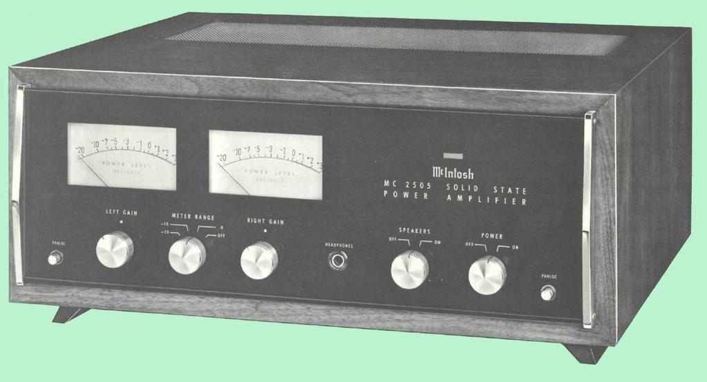
4 GENERAL DESCRIPTION TECHNICAL DESCRIPTION The dramatic difference in the quality of music reproduced through a Mclntosh instrument is due to low distortion. The distortion of your MC2505 is guaranteed to be less than 0.25% at any frequency from 20 Hz to 20 khz with both channels operating at 50 watts RMS. Distortion is measured at full rated power output with both channels operating. At less than rated power, distortion becomes so small it can be measured only by the most sophisticated laboratory instruments. Only Mclntosh gives you this kind of performance. Your MC2505 passed more than 75 tests before it was ready for you. Each connection, wire, resistor, capacitor is checked and rechecked. All specifications are checked. Mclntosh testing takes time. The extra investment in thorough testing assures you of greater musical enjoyment. The performance of your Mclntosh MC2505 is backed by a money back guarantee. Only Mclntosh gives you a money back guarantee of performance. Your MC2505 must be capable of meeting its published specifications or you get a refund of your purchase price. Mclntosh promises performance. We either meet our promise or you get your money back. Your MC2505 can be protected by a free three year factory service contract. Take advantage of this service. Fill in the application card found in the owner's packet. The free three year factory service contract covers parts and labor. If anything goes wrong just bring your MC2505 to a factory service station, or return your MC2505 to Mclntosh. All parts and labor necessary to repair your MC2505 will be supplied free of charge. Fill in the service contract application found in the owner's packet now. 2 A two stage preamplifier with three transistors in each channel increases the input voltage 16 db. There are 13 transistors in each power amplifier section. The two stage preamplifier is fed to a pair of matched transistors arranged as an emitter coupled amplifier with two inputs and one output. The signal from the preamplifier section connects to one of these inputs. Both AC and DC negative feedback are applied to the other input. This large quantity of feedback is used to reduce noise and distortion. The signal is then fed to a voltage amplifier. The voltage amplifier is followed by two driver transistors. The output section is arranged as a series push-pull amplifier. The power transistors used in the output section of your MC2505 are selected for their high power dissipation capability, wide frequency response, and large "safe operating area." In addition, each power transistor is given four separate tests before it is put in your MC This additional testing makes sure your MC 2505 will deliver its rated power from 20 to 20 khz with low distortion and complete reliability. The power transistors are mounted on oversized anodized heat sinks. The heat sinks assure that under normal operation the transistors will operate at a low temperature. If temperatures increase due to a shorted speaker, or restricted ventilation, an automatic temperature sensing device turns off the MC2505. The device operates automatically at a preset temperature. The MC 2505 will turn on again when the temperature has returned to normal limits. This additional feature gives your MC2505 complete reliability under the most extreme operating conditions.

5 The output stages are matched to the load by the Mclntosh autoformer. The Mclntosh autoformer is carefully wound using Mclntosh trifilar winding and interleaving techniques. Trifilar winding and interleaving gives the transformers exceptional bandwidth. The autoformers properly match the power transistors to 4, 8, and 16 ohm loads at all audio frequencies. The use of the Mclntosh designed trifilar autoformer makes the Mclntosh solid state amplifiers the only amplifiers that deliver FULL POWER AT ALL SPEAKER IMPEDANCES. You have not been power penalized for your choice of loudspeakers when using the Mclntosh MC2505. Another of the advantages of the autoformers is the 25 volt output for a constant voltage distribution system. With the MC2505 several sets of speakers can be operated independently throughout your home. To further insure reliability a special power output SENTRY MONI- TORING CIRCUIT prevents failure of the power output transistors due to excessive mismatch of the output. When your MC2505 operates normally the SENTRY MONITORING CIRCUIT has no effect on signals passing through the power amplifier. If the power dissipation should rise above normal operation, the SEN- TRY MONITORING CIRCUIT restricts the drive to the output transistors. The SENTRY MONITORING CIRCUIT acts instantaneously for any input signal or load combination. This arrangement assures complete circuit reliability. Only Mclntosh gives you this degree of protection. POWER SUPPLY SECTION There are three separate power supply sections. One positive and one negative high current supply is used for the output stages. The other positive supply is used for the driving amplifier stages. All supplies are full wave and use silicon rectifiers. Adequate filtering is used to assure an absolute minimum of hum. The power output stage filter capacitors have very high capacity, which allows full power output below 20 Hz. The power transformer is generous in size and runs cool, even under heavy use. 3

6 DYNAMIC PEAK LOCKING METERS Ordinary meters lack the capability of indicating the short interval power in a sound wave. The mass of the meter movement is too great to respond to instantaneous changes in music program material. Mclntosh superior engineering has developed new circuitry that permits the meters on the MC2505 to respond to the short interval power in a sound wave to an accuracy of 98% of the true value. This is another Mclntosh development that represents a major step forward in the use of power level meters. There are two circuits that give these meters the indicating capability of the short interval power in a sound wave. The first circuit is an accelerating circuit that compensates for the inertia characteristics of the meter movement. Because the short interval power fluctuation is so rapid, the eye might not perceive the instantaneous power reading. This caused the development of the second circuit, which is a "time stretching" circuit. The time stretching circuit delays the movement of the meter needle at peak reading for a few milliseconds. With the aid of the CBS test record STR100, the frequency response of your phono cartridge can be measured. The graph on page 5 shows the ideal RIAA curve using the CBS record STR100. Follow these steps to plot the performance of your phonograph cartridge. 1. Set the "METER RANGE SWITCH" to the 20 position. 2. Play the 1000 Hz test tone recorded on the CBS Test Record STR100 on your phonograph. 3. Turn the "LEFT GAIN" control until the left meter indicates "0." 4. Turn the "RIGHT GAIN" control until the right meter indicates "O." 5. Write down the meter indication at each frequency as the record plays. 6. Transfer the readings by frequency to the graph. 7. The graph shows the ideal RIAA response curve using the CBS #STR100 test record. Compare your curve with the curve on the graph. A deviation of 3 db from the ideal is acceptable. By making this check at regular intervals, (for instance, every 6 months) any deterioration in the cartridge or system will be quickly detected. A tape recorder can be checked in the same fashion. 1. Use a standard frequency response tape as the signal source. 2. Complete all steps outlined for phono cartridges. 3. You now have a graph of the playback characteristics of your tape recorder. To find the record characteristics of the tape recorder follow this procedure: 1. Record the CBS Test Record #STR100 on your tape recorder. Adjust the record volume only on the 1000 Hz signal for proper recording level. DO NOT ADJUST THE RECORD VOLUME CONTROL DUR- ING THE RECORDING. 2. Play back the tape just recorded. Complete all steps outlined for tape playback characteristics. 3. A comparison of the two curves will give the recording characteristics of your tape recorder. A deviation of 3 db is acceptable. Similar checks can be made on all program sources in your stereo system. Follow the same general procedure for any program source for which a standard reference is available. 1


7 RELATIVE OUTPUT LEVEL IN db RELATIVE OUTPUT LEVEL IN db IDEAL RIAA SYSTEM RESPONSE USING CBS STR 100 TEST RECORD k 10k 20k -20 FREQUENCY IN Hz IDEAL RIAA SYSTEM RESPONSE USING CBS STR 100 TEST RECORD k 10k 20k FREQUENCY IN Hz


8 RELATIVE OUTPUT LEVEL IN db RELATIVE OUTPUT LEVEL IN db IDEAL RIAA SYSTEM RESPONSE USING CBS STR 100 TEST RECORD 100 1k 10k 20k FREQUENCY IN Hz IDEAL RIAA SYSTEM RESPONSE USING CBS STR 100 TEST RECORD 100 1k 100k 20k FREQUENCY IN Hz
9 7


10 TYPICAL PERFORMANCE DATA 70 POWER OUTPUT vs FREQUENCY 60 POWER OUTPUT RMS WATTS FREQUENCY IN HERTZ 1 k 10k 100k HARMONIC DISTORTION vs POWER OUTPUT INTERMODULATION DISTORTION vs POWER OUTPUT PERCENTAGE HARMONIC DISTORTION PERCENTAGE INTERMODULATION DISTORTION POWER OUTPUT IN RMS WATTS 20 Hz 2kHz 20kHz 10 POWER OUTPUT IN EQUIVALENT RMS WATTS 100 8
11 SPECIFICATIONS ELECTRICAL SPECIFICATIONS: POWER OUTPUT: STEREO 50 RMS watts continuous per channel into 4, 8, or 16 ohms both channels operating. HARMONIC DISTORTION: STEREO Less than 0.25% at 50 watts output from 20 Hz to 20 khz both channels operating. Typical performance is less than 0.1% at rated power. Distortion decreases as output power is reduced. INTERMODULATION DISTORTION: STEREO Less than 0.25% if instantaneous peak power output is 100 watts or less per channel with both channels operating for any combination of frequencies 20 Hz to 20 khz. FREQUENCY RANGE: 20 Hz to 29kHz +0, -0.1 db at rated power. 15 Hz to 60 khz +0, -0.5 db at rated power. 10 Hz to 100 khz +0, -3.0 db at one-half of rated power. NOISE AND HUM: 90 db or more below rated output. OUTPUT IMPEDANCE: STEREO 4, 8, and 16 ohms OUTPUT VOLTAGES: 25 volts STEREO DAMPING FACTOR: 14 at 4 ohms output 27 at 8 ohms output 13 at 16 ohms output INPUT IMPEDANCE: 200,000 ohms INPUT SENSITIVITY: 0.5 volt. Level control provided for higher input voltage. POWER REQUIREMENTS: 117 volts AC 50/60 Hz, 75 watts at zero signal output. 250 watts at rated output. SEMICONDUCTOR COMPLEMENT: 26 silicon transistors. 27 silicon rectifiers and diodes. MECHANICAL SPECIFICATIONS: SIZE: 5-7/16 inches high, 16 inches wide, 13 inches deep. CHASSIS: Chrome and black. WEIGHT: 38 pounds net, 53 pounds in shipping carton. SPECIAL FEATURES The amplifier is completely stable when connected to any loudspeaker system or even to any reactive loads. The MC 2505 has special circuits to prevent damage by short circuit or open circuit of the output loads, or by any amount of output impedance mismatch. Thermal cutouts are mounted on the output transistor heat sinks to provide protection in the event of inadequate ventilation. 9

12 IF YOU'RE IN A HURRY POWER OFF ON Turns the amplifier on/off. SPEAKER OFF ON Turns the speaker on / off. HEADPHONE To connect a set of low impedance stereo headphones. METER RANGE Adjust meter readings to power output level. 10
 rise in temperature reduces the life of electrical insulation by one half.")


13 Adequate ventilation extends the trouble-free life of electronic instruments. It is generally found that each 10 centigrade (18 F) rise in temperature reduces the life of electrical insulation by one half. Adequate ventilation is an inexpensive and effective means of preventing insulation breakdown that results from unnecessarliy high operating temperatures. The direct benefit of adequate ventilation is longer, trouble-free life. The suggested minimum space for mounting the MC 2505 is 14 inches long x 16½ inches wide x 6 inches high. Always allow for air flow by either ventilation holes or space next to the bottom of the amplifier and a means for the warm air escape at the top. It is recommended that the MC2505 be mounted in a normal or horizontal position. However, with adequate ventilation the amplifier can be mounted in any position. To prepare the MC2505 for installation remove the plastic protective covering. Turn the MC 2505 upside down so that it rests on its top on the shipping pallet. Remove the four plastic feet fastened to the bottom of the chassis. Next place the mounting brackets, the parts bag and the mounting template for easy accessibility. The professional mounting design eliminates the need for any shelf or bracket to support the MC2505. It is completely supported by its own mounting brackets. INSTALLATION of the cabinet panel to be cut out for installation. The design of the mounting template allows you to position or locate the cutout from the front or rear of the panel to which the instrument is to be mounted. If the cutout is to be located from the rear of the panel, the following steps will help you. On the back of the cabinet panel, scribe a vertical centerline through the exact center of the area in which the cutout is to be made. Place the template against the back of the panel and match the template centerline with the centerline on the cabinet panel. Make sure that there is at least ¼ inch clearance between the bottom of the dashed line of the cutout area on the template and any shelf or brace below the proposed cutout. Mark the two locating holes ("C" holes on the mounting template). Drill the two locating holes. Be certain the drill is perpendicular to the panel. Now position the template on the front of the panel by aligning the "C" locating holes on the template with the drill holes. With the template in place against the cabinet panel, mark the "A" and "B" drill holes and the four small holes that identify corners of the cutout. Join the corner marks with a pencil. The edge of the template can be used as a straight edge. IMPORTANT: DRILL THE 6 HOLES BEFORE MAKING THE CUTOUT Accurately drill the three holes on each side of the cutout area with a 3 / 16 inch drill. With the saw on the INSIDE OF THE PENCIL LINES carefully cut out the rectangular opening. Secure the mounting strips to the rear of the cabinet panel using two screws from the hardware package. Insert the screws in the center holes of the cabinet panel ("B" holes on the template) and tighten. The screw head should pull into the wood slightly. (Use two ¾ inch long screws for panels under ½ inch, or two 1¼ inch long screws for panels ½ inch thick and larger.) Attach the mounting brackets to the cabinet panel using four screws. Place the template over the mounting screws. The mounting screws should be centered in the "A" and 'B" holes on the template. The sides of the mounting brackets should match the vertical dash lines on the template. If necessary, loosen the screws and push the brackets into alignment and retighten. Insert the power cord through the opening. Carefully slide the MC 2505 into the opening so the rails on the bottom of the equipment slide in the track of the mounting brackets. Continue to slide the instrument in until the front panel is against the cabinet panel. At the bottom front corners of the PANLOC instruments are the PANLOC buttons. Depressing the PANLOC buttons will lock the instrument firmly in the installation. Depressing the PANLOC buttons a second time (as with a ball-point pen) will release the instrument. You can then slide the instrument forward to the inspectionadjustment position. Depressing the inspection-adjustment position latches will allow the instrument to be slid completely out of the installation. Position the plastic mounting template over the area DO NOT USE THE SPRINGS ON HORIZONTALLY MOUNTED EQUIPMENT. VERTICAL INSTALLATION In the hardware packet are two helical springs. Fasten the springs to the small flanges at the rear of the PANLOC brackets. The flange has a notch and a hole to mount the spring. The springs assist in the removal of vertically mounted PANLOC equipment. 11


14 TYPICAL HOOK UP TUNER DIRECTIONAL FM ANTENNA ROTATOR PREAMPLIFIER TO 117 V AC OUTLET AC LINE ALTERNATE SPEAKER LEAD CONNECTION TO BE USED WHEN PHASE SWITCH AND PHONE JACK ON C24 ARE TO BE USED. AC LINE MC2505 POWER AMPLIFIER 12

15 CONNECTING THE MC2505 INPUT-STEREO The shielded cable from the left output of the Mclntosh preamplifier is plugged into the left jack. The shielded cable from the right output of the Mclntosh preamplifier is plugged into the right jack. SPEAKERS Speakers are connected at the barrier strips marked OUT- PUT on the back panel of the amplifier. Use lamp cord, bell wire, or wire with similar type of insulation to connect the speakers to the amplifier. For the normally short distances of under 50 feet between the amplifier and speaker, #18 wire or larger can be used. For distances over 50 feet between the amplifier and speaker use larger wire. The loudspeaker impedance is usually identified on the loudspeaker itself. Connect one of the leads from the left loudspeaker to the screw marked COM on the LEFT OUT- PUT barrier strip. Connect the other lead from the left loudspeaker to the screw marked with the number corresponding to the speaker impedance on the LEFT OUT- PUT barrier strip. Connect one of the leads from the right loudspeaker to the screw marked COM on the RIGHT OUTPUT barrier strip. Connect the other lead from the right loudspeaker to the screw marked with the number corresponding to the speaker impedance on the RIGHT OUTPUT barrier strip. The only adverse effect on the operation of a Mclntosh amplifier when it is improperly matched is a reduction in the amount of distortion-free power available to the loudspeaker. Close impedance matching is desirable for maximum distortion-free power. SPEAKER CONNECTIONS Use this table to determine proper speaker connection: Connect the If the speaker impedance speaker leads is between: between COM and: 3.2 to 6.5 ohms 4 ohms 6.5 to 13 ohms 8 ohms 13 to 26 ohms 16 ohms Connect as follows: If the speaker impedance is: 4 ohms 8 ohms 16 ohms Connect one left speaker to screw LEFT-COM and other to: LEFT-4 LEFT-8 LEFT-16 DO NOT CONNECT Connect one right speaker lead to the screw marked RIGHT-COM and the other to: RlGHT-4 RIGHT-8 RlGHT-16 A MONOPHONIC LOUDSPEAKER TO BOTH TERMINALS. THE LOUDSPEAKER CAN BE DAMAGED. For 25 volt line operation connect one of the left leads to the screw marked COM on the LEFT OUTPUT barrier strip. The other left lead is connected to the screw marked 16 on the LEFT OUTPUT barrier strip. Connect the right leads in the same manner on the RIGHT OUTPUT barrier strip. AC POWER: The MC2505 operates on 117 to 130 volt, 50/60 Hz. The amplifier will be turned on and off if its power cord is plugged in one of the auxiliary AC outlets on the program source. 13
16 14 BLOCK DIAGRAM

17 OPERATING THE MC 2505 STEREO AMPLIFIER LEFT GAIN Use the left gain control to adjust the volume in the left channel to the desired listening level. Turn the control clockwise to increase the volume. RIGHT GAIN Use the right gain control to adjust the volume in the right channel to the desired listening level. Turn the control clockwise to increase the volume. METER RANGE The meter switch has four positions. The first position is off. With the switch in the OFF position there is no indication on the meters. - 20: In this position of the meter range switch, the amplifier will deliver ¼ watt (250 milliwatts) when the meter indicates "0." With a meter indication or 3 db, the amplifier delivers % watt (125 milliwatts) and a 10 db meter indication the amplifier delivers 25 milliwatts. -10: In this position of the meter range switch, the amplifier will deliver 2½ watts output when the meter indicates "0." With a meter indication of 3 db, the amplifier delivers 1 ¼ watts output and a 10 db meter indication, the amplifier delivers ¼ watts. 0: In this position of the meter range switch, the amplifier will deliver 50 watts when the meter indicates +3 db, with meter indication of "0," the amplifier delivers 25 watts, with a meter indication of -3 db, the amplifier delivers 12½ watts; and a meter indication of -10 db, the amplifier delivers 2½ watts. HEADPHONE Use the jack for low impedance stereo headphones. Any headphones with 4, 8,16 ohms may be used with this jack. The headphone jack is on at all times. SPEAKERS OFF: The loudspeakers are turned off when the SPEAKER switch is in the OFF position. You can listen to headphones in private. THIS SWITCH MUST BE IN THE "ON" POSI- TION TO HEAR MUSIC FROM THE LOUD- SPEAKERS. ON: Music will be heard through the loudspeakers. Use this as the normal listening position. POWER The power switch turns the MC 2505 on or off. The switch does not control the power outlet on the back panel. If you wish to control the operation of the on/off switch from a preamplifier control center leave the switch in the ON position. In this case be sure to plug the AC cord of the MC 2505 into the controlled outlets on the rear of the preamplifier control center. OFF: In the OFF position the amplifier is turned off. 15
18 GUARANTEE Mclntosh Laboratory Incorporated guarantees this equipment to be capable of performance as advertised. We also guarantee the mechanical and electrical workmanship and components of this equipment to be free of defects for a period of 90 days from date of purchase. This guarantee does not extend to components damaged by improper use nor does it extend to transportation to and from the factory. 3 YEAR FACTORY SERVICE CONTRACT An application for a FREE 3 YEAR FACTORY SERVICE CONTRACT is included in the pack with this manual. The FREE 3 YEAR FAC- TORY SERVICE CONTRACT will be issued by Mclntosh Laboratory upon receipt of the completely filled out application form. The terms of the contract are: 1. Transportation charges are excluded. 2. This agreement is given to the original purchaser only and is not transferable. 3. The application for the contract must be filled out completely. 4. If the instrument has been modified or damaged by unauthorized repair the contract will be cancelled. 5. To receive free service, the contract must be presented to the factory authorized service agency, when the equipment is presented for repair. If the application is not received at Mclntosh Laboratory, only the service offered under the standard 90 day guarantee will apply on this equipment. Your MC2505 stereo power amplifier will give you many years of pleasant and satisfactory performance. If you have any questions concerning operation or maintenance please contact the dealer from whom you purchased this instrument or: CUSTOMER SERVICE Mclntosh Laboratory Inc. 2 Chambers Street Binghamton, N. Y Our telephone number is MC25O5 16 TAKE ADVANTAGE OF 3 YEARS OF FREE FACTORY SERVICE BY FILLING IN THE APPLICATION NOW
19
20 MclNTOSH LABORATORY INC. 2 CHAMBERS ST., BINGHAMTON, N. Y Design subject to change without notice. Printed in U.S.A BE042003
MC24O OWNER'S MANUAL STEREO POWER AMPLIFIER CONTENTS
 STEREO POWER AMPLIFIER MC24O CONTENTS GENERAL DESCRIPTION 1 TECHNICAL DESCRIPTION 1 PANEL FACILITIES 4 INSTALLATION 5 CONNECTIONS 5 Input Stereo 5 Input Twin Amp 5 Input Mono 6 Output Stereo or Twin Amp
THE MclNTOSH MC 2300 SOLID STATE STEREO POWER AMPLIFIER
 THE MclNTOSH MC 2300 SOLID STATE STEREO POWER AMPLIFIER Price $1.25 The Mclntosh MC 2300 is a high quality, extremely high power, solid state stereo amplifier. Because of the high power available it is
THE MclNTOSH MC 2255 SOLID STATE STEREO POWER AMPLIFIER
 THE MclNTOSH MC 2255 SOLID STATE STEREO POWER AMPLIFIER Reading Time: 31 Minutes Price $2.00 VARIOUS REGULATORY AGENCIES REQUIRE THAT WE BRING THE FOLLOWING INFORMATION TO YOUR ATTENTION. PLEASE READ IT
Contents. The Mclntosh compact Family MR 500 DIGITAL FM TUNER
 Contents SERVICE CONTRACT INFORMATION 1 INTRODUCTION 2 INSTALLATION 3, 4 BACK PANEL CONNECTIONS AND CONTROLS 5, 6 USING THE FRONT PANEL CONTROLS 7, 8 HOW THE CIRCUITS WORK 9, 10 PERFORMANCE LIMITS 11 PERFORMANCE
MC2301. Features and Benefits. Promotional Highlights TUBE POWER AMPLIFIER MCINTOSH LABORATORY INC., 2 CHAMBERS STREET, BINGHAMTON, NEW YORK 13903
 MC2301 Product Preview Page 1 McIntosh Laboratory, Inc., Binghamton, NY 13903 Design Engineering Department PRODUCT PREVIEW MC2301 TUBE POWER AMPLIFIER Project 1336 Promotional Highlights 300 Watts Mono
MR65 OWNER'S MANUAL STEREO FM TUNER ISSUE NO. 2. Reading Time 30 Minutes Price $1.25
 STEREO FM TUNER MR65 TABLE OF CONTENTS GENERAL DESCRIPTION 1 TECHNICAL DESCRIPTION 1 FRONT PANEL FACILITIES 2 Dial Scale 2 Meters 2 Volume Control 2 Mode Selector 2 Auto. Freq. Control 3 Muting 3 BACK
THE McINTOSH MR 78 SOLID STATE FM/FM STEREO TUNER
 THE McINTOSH MR 78 SOLID STATE FM/FM STEREO TUNER Reading Time 32 Minutes Price $1.25 Your MR 78 FM/FM Stereo Tuner will give you many years of pleasant and satisfactory performance. If you have any questions
MA 5100 SERVICE INFORMATION PREAMP - AMPLIFIER. MclNTOSH LABORATORY INC. 2 CHAMBERS STREET BINGHAMTON, NEW YORK STARTING WITH SERIAL NO.
 PREAMP - AMPLIFIER SERVICE INFORMATION STARTING WITH SERIAL NO. 21HOO MclNTOSH LABORATORY INC. 2 CHAMBERS STREET BINGHAMTON, NEW YORK ELECTRICAL SPECIFICATIONS Power Output: 90 watts RMS continuous, 45
MZ2 HEADPHONE AMPLIFIER, PREAMP, & STEREO AMPLIFIER USER GUIDE
 MZ2 HEADPHONE AMPLIFIER, PREAMP, & STEREO AMPLIFIER USER GUIDE Linear Tube Audio Takoma Park, MD, USA WARNING: For safety, the cover of this amplifier should be secured at all times. DC voltages as high
MC312 Power Amplifier Owner s Manual
 McIntosh Laboratory, Inc. 2 Chambers Street Binghamton, New York MC312 Power Amplifier Owner s Manual 13903-2699 Phone: 607-723-3512 www.mcintoshlabs.com Important Safety Information is supplied in a separate
MC462 Quad Balanced Power Amplifier Owner s Manual
 McIntosh Laboratory, Inc. 2 Chambers Street Binghamton, New York MC462 Quad Balanced Power Amplifier Owner s Manual 13903-2699 Phone: 607-723-3512 www.mcintoshlabs.com Important Safety Information is supplied
MC75 Tube Power Amplifier Owner s Manual
 McIntosh Laboratory, Inc. 2 Chambers Street Binghamton, New York MC75 Tube Power Amplifier Owner s Manual 13903-2699 Phone: 607-723-3512 www.mcintoshlabs.com 2 The lightning flash with arrowhead, within
MODEL 3 MONO AMPLIFIER OWNER S MANUAL
 MODEL 3 MONO AMPLIFIER OWNER S MANUAL TABLE OF CONTENTS Introduction Features Unpacking Instructions Installation * Space requirements * A.C. connections Input Impedance Selection Adjustable Gain Signal
19'' Rack Mount 300 Watt Power Amplifier/ Mixer w/70v Output & Mic Talkover USER MANUAL
 19'' Rack Mount 300 Watt Power Amplifier/ Mixer w/70v Output & Mic Talkover USER MANUAL Your new PYRAMID PA305 300 Watt P.A. Amplifier gives you the power and versatility you need in a professional sound
ALM473 DUAL MONO \ STEREO AUDIO LEVEL MASTER OPERATION MANUAL IB
 ALM473 DUAL MONO \ STEREO AUDIO LEVEL MASTER OPERATION MANUAL IB6408-01 TABLE OF CONTENTS GENERAL DESCRIPTION 2 INSTALLATION 2,3,4 CONNECTION AND SETUP 4,5,6,7 FUNCTIONAL DESCRIPTION 8,9 MAINTENANCE 9
Installation & User Guide. For Powering Distributed Audio Systems A45-X2 TWO CHANNEL AMPLIFIER
 Installation & User Guide For Powering Distributed Audio Systems TWO CHANNEL AMPLIFIER A45-X2 A45-X2 TWO CHANNEL AMPLIFIER TABLE OF CONTENTS Features...1 Product Overview...2 Package Contents...4 Preparing
FMR622S DUAL NARROW BAND SLIDING DE-EMPHASIS DEMODULATOR INSTRUCTION BOOK IB
 FMR622S DUAL NARROW BAND SLIDING DE-EMPHASIS DEMODULATOR INSTRUCTION BOOK IB 1222-22 TABLE OF CONTENTS SECTION 1.0 INTRODUCTION 2.0 INSTALLATION & OPERATING INSTRUCTIONS 3.0 SPECIFICATIONS 4.0 FUNCTIONAL
MciNTOSH MODEL Me-30
 INSTRUCTION MANUAL MciNTOSH MODEL Me-30 30 WATT POWER AMPLIFIER Type A-116B Serial # 15329 and Over MciNTOSH LABORATORY, INC 2 Chambers St. Binghamton, N. Y. U.S.A. 1.5M 757 HPB ELECTRICAL AND MECHANICAL
TOA PROFESSIONAL POWER AMP
 Operating Instruction Manual TOA PROFESSIONAL POWER AMP Model P-150M, P-300M TOA ELECTRIC CO, LTD. KOBE, JAPAN Contents Precautions... 2 General Description... 2 Features... 3 Specifications... 4~5 Performance
audionet 4 Channel Amplifier Owner's Manual
 audionet amp Iv 4 Channel Amplifier Owner's Manual Congratulations! For those in need of even more amplification we have engineered the AMP IV. The AMP IV is our power amplifier for multichannel applications
Owner s Manual.
 P Z R 6 0 0 A m p l i f i e r P Z R 1 0 0 0 A m p l i f i e r Owner s Manual www.pyleaudio.com Your New Pyle Pro PZR series P.A. Amplifier gives you the power and versatility you need in a professional
MR66 STEREO TUNER TABLE OF CONTENTS
 MR66 STEREO TUNER MR66 TABLE OF CONTENTS INTRODUCTION TECHNICAL DESCRIPTION FRONT PANEL INFORMATION BACK PANEL INFORMATION INSTALLATION CONNECTING Monophonic FM and AM Stereophonic FM and AM Stereophonic
OPERATING THE SYLVANIA STEREO RECEIVER RS4743
 OPERATING THE SYLVANIA STEREO RECEIVER RS3 TABLE OF CONTENTS Page Introduction 2 Accessory Components 3 Initial Hook-Up Connecting Accessory Components Antenna Connections Jacks Aux Jacks Tape Jacks Pre-Amp
POWER AMPLIFIER. Owner s Manual Mode d emploi Bedienungsanleitung Manual de instrucciónes CLIP SIGNAL TEMP PROTECTION POWER
 POWER AMPLIFIER Owner s Manual Mode d emploi Bedienungsanleitung Manual de instrucciónes TEMP PROTECTION POWER A CLIP SIGNAL B ON OFF M Introduction Thank you for purchasing a Yamaha C450/320/160 series
MC1000 POWER AMPLIFIER
 MC1000 POWER AMPLIFIER MC1000 POWER AMPLIFIER IMPORTANT SAFETY INSTRUCTIONS THESE INSTRUCTIONS ARE TO PROTECT YOU AND THE MclNTOSH INSTRUMENT. BE SURE TO FAMILIARIZE YOURSELF WITH THEM Copyright 1992
GE Monogram. Installation. Instructions. Microwave Oven. Under Cabinet Installation. and. JX827 Series Built-In Kit. Models.
 GE Monogram Installation Instructions Under Cabinet Installation and JX827 Series Built-In Kit Models ZEM200 Series CAUTION WARNING Before you begin Read these instructions completely and carefully. IMPORTANT:
CON NEX HP. OWNER'S MANUAL Full Channel AM/FM Amateur Mobile Transceiver TABLE OF CONTENTS TUNING THE ANTENNA FOR OPTIMUM S.W.R..
 TABLE OF CONTENTS PAGE SPECIFICATIONS... 2 INSTALLATION... 3 LOCATION... 3 CON NEX - 4300HP MOUNTING THE RADIO... 3 IGNITION NOISE INTERFERENCE... 4 ANTENNA... 4 TUNING THE ANTENNA FOR OPTIMUM S.W.R..
FEATURES AND BENEFITS PROMOTIONAL HIGHLIGHTS MCINTOSH LABORATORY INC., 2 CHAMBERS STREET, BINGHAMTON, NEW YORK MC206 Product Preview Page 1
 MC206 Product Preview Page 1 McIntosh Laboratory, Inc., Binghamton, NY 13903 Design Engineering Department PRODUCT BRIEF MC206 SIX CHANNEL POWER AMPLIFIER Project 1160 Contents Promotional Highlights 1
Studio MODEL:PA600X/PA800X/PA1000X/ PA1800X PA AMPLIFIER PRO. High Performance Professional Audio.
 Studio PRO High Performance Professional Audio MODEL:PA600X/PA800X/PA1000X/ PA1800X PA AMPLIFIER www.pyramidcaraudio.com INTRODUCTION Your New PYRAMID PA SERIES AMPLIFIER gives you the power and versatility
IMPORTANT SAFETY INSTRUCTIONS
 IMPORTANT SAFETY INSTRUCTIONS THESE INSTRUCTIONS ARE TO PROTECT YOU AND THE MclNTOSH INSTRUMENT. BE SURE TO FAMILIARIZE YOURSELF WITH THEM. 1. Read all instructions - Read the safety and operating instructions
Studio. PRO High Performance Professional Audio MODEL:PA105/PA205 PA AMPLIFIER
 Studio PRO High Performance Professional Audio MODEL:PA105/PA205 PA AMPLIFIER INTRODUCTION Your New PYRAMID PA105/PA205 PA AMPLIFIER gives you the power and versatility you need in a professional sound
Power Amplifier. MC501 Owner s Manual
 Power Amplifier MC501 Owner s Manual McIntosh Laboratory, Inc. 2 Chambers Street Binghamton, New York 13903-2699 Phone: 607-723-3512 FAX: 607-724-0549 The lightning flash with arrowhead, within an equilateral
FOUNTEK ALTITUDE Integrated Amplifier OWNERS MANUAL. A3500 ( Version -V1) 240V AC
 240V AC") FOUNTEK ALTITUDE 3500 Integrated Amplifier OWNERS MANUAL A3500 ( Version -V1) 240V AC 24-10-05 CONTENTS 3. INTRODUCTION 4. IMPORTANT NOTES ( WARNING!) 5. POWER INPUT CONNECTION 6. CONNECTING SPEAKERS 7.
FOUNTEK ALTITUDE 3500 Integrated Amplifier OWNERS MANUAL A3500 ( Version -V1) 240V AC 24-10-05 CONTENTS 3. INTRODUCTION 4. IMPORTANT NOTES ( WARNING!) 5. POWER INPUT CONNECTION 6. CONNECTING SPEAKERS 7.
Electro-Voice S40. Full Range Compact Speaker System 160 Watts Power Handling Available is Black or White
 Electro-Voice S40 Full Range Compact Speaker System 160 Watts Power Handling Available is Black or White NOTE: This data sheet refers to several graphs. In order to keep the size of this document reasonable
Instruction Kit MIXER AMPLIFIER GT 60C GT 125C. GROMMES-PRECISION SINCE-46
 Instruction Kit GT 60C GT 125C MIXER AMPLIFIER GROMMES-PRECISION 1-800-SINCE-46 www.grommesprecision.com Thank you for purchasing from Grommes~Precision! Grommes~Precision and its commercial audio division,
MASTR II AUXILIARY RECEIVER 19D417546G7 & G8 & ANTENNA MATCHING UNITS 19C321150G1-G2. Maintenance Manual LBI-30766L. Mobile Communications
 L Mobile Communications MASTR II AUXILIARY RECEIVER 19D417546G7 & G8 & ANTENNA MATCHING UNITS 19C321150G1-G2 Printed in U.S.A Maintenance Manual TABLE OF CONTENTS Page SPECIFICATIONS.....................................................
3050 Stereo Power Amplifier
 3050 Stereo Power Amplifier Owners Manual 10/26/2016 Boulder Amplifiers, Inc. 255 Taylor Ave. Louisville, CO 80027 (303) 449-8220 www.boulderamp.com Fault Conditions Boulderlink Appendix Remote Control
ZOTL40 Mk.II POWER AMPLIFIER USER GUIDE. Linear Tube Audio Takoma Park, MD, USA
 ZOTL40 Mk.II POWER AMPLIFIER USER GUIDE Linear Tube Audio Takoma Park, MD, USA WARNING: For safety, the cover of this amplifier should be secured at all times. DC voltages as high as 1000V and peak AC
INSTALLATION & OPERATION GUIDE. SVC100R High-Power Sliding Volume Control
 INSTALLATION & OPERATION GUIDE SVC100R High-Power Sliding Volume Control B L E N D I N G H I G H F I D E L I T Y A N D A R C H I T E C T U R E SVC100R INTRODUCTION TABLE OF CONTENTS Introduction 1 Features
Phono3. Two Channel Analog RIAA MM/MC Pre-Amplifier
 User's Guide Phono3 e.one Series Two Channel Analog RIAA MM/MC Pre-Amplifier Bel Canto Design, LTD. 221 North First Street Minneapolis, MN 55401 Phone: (612) 317.4550 Fax: (612) 359.9358 www.belcantodesign.com
411LA Broadband Power Amplifier
 411LA Broadband Power Amplifier HIGH RF VOLTAGES MAY BE PRESENT AT THE OUTPUT OF THIS UNIT. All operating personnel should use extreme caution in handling these voltages and be thoroughly familiar with
Household Appliances. Over-the-Range Microwave. Installation Instructions. For Models: HMV9302, HMV9305, HMV9306, HMV9307
 Over-the-Range Microwave Household Appliances Installation Instructions For Models: HMV9302, HMV9305, HMV9306, HMV9307 PLEASE READ ENTIRE INSTRUCTIONS BEFORE PROCEEDING IMPORTANT: Save these instructions
Restoration Performance Report
 Restoration Performance Report Report Date: July 15, 2015 Manufacturer: Fisher Model: 500-C Receiver Special Notes: Full Gold Level Restoration service completed. Chassis ultrasonically cleaned. All coupling
Over the Range Microwave Oven
 Over the Range Microwave Oven BEFORE YOU BEGIN Read these instructions completely and carefully. IMPORTANT Save these instructions for local inspector s use. IMPORTANT and ordinances. Observe all governing
MC302 Power Amplifier Owner s Manual
 McIntosh Laboratory, Inc. 2 Chambers Street Binghamton, New York MC302 Power Amplifier Owner s Manual 13903-2699 Phone: 607-723-3512 www.mcintoshlabs.com 2 The lightning flash with arrowhead, within an
audionet AMP 1 V2 User s Manual Stereo - Amplifier
 audionet AMP 1 V2 Stereo - Amplifier User s Manual 1 2 Contents 1 Preface... 4 1.1 Included... 5 1.2 Transport... 5 2 Overview control elements... 6 2.1 Front panel... 6 3 Overview connections... 7 3.1
F O R T H E L O V E O F M U S I C SERIES 218 DPS200 OWNER'S MANUAL AND INSTALLATION GUIDE INTRODUCTION
 F O R T H E L O V E O F M U S I C SERIES 218 DPS200 OWNER'S MANUAL AND INSTALLATION GUIDE INTRODUCTION You have purchased an amplifier that leads the way with sound quality, reliability, and features.
TOA 500 SERIES MIXER POWER AMPLIFIER
 TOA 500 SERIES MIXER POWER AMPLIFIER Operation Instruction Manual A-503A A-506A A-512A Features General Description 1. High quality design and construction. 2. Full frequency response: 50-15,000Hz, ±3dB.
SPEAKER SELECTION/VOLUME CONTROL SYSTEM
 M O D E L SVL-2 SVL-2 SPEAKER SELECTION/VOLUME CONTROL SYSTEM NILES INSTALLATION & OPERATION GUIDE SVL-2 Speaker Selection/ Volume Control System TABLE OF CONTENTS Introduction 1 Features and Benefits
F O R T H E L O V E O F M U S I C LP100 OWNER'S MANUAL AND INSTALLATION GUIDE INTRODUCTION
 F O R T H E L O V E O F M U S I C LP100 OWNER'S MANUAL AND INSTALLATION GUIDE INTRODUCTION You have purchased an amplifier that leads the way with sound quality, reliability, and features. These high performance
LBI-4938C. Mobile Communications MASTR II POWER AMPLIFIER MODELS 4EF4A1,2,3. Printed in U.S.A. Maintenance Manual
 C Mobile Communications MASTR II POWER AMPLIFIER MODELS 4EF4A1,2,3 Printed in U.S.A. Maintenance Manual TABLE OF CONTENTS DESCRIPTION.................................................... 1 CIRCUIT ANALYSIS.................................................
TABLE OF CONTENTS. 1) Introduction 2. 2) Unpacking your preamplifier 2. 3) Installing the preamp into your system 3
 Introduction 2. 2) Unpacking your preamplifier 2. 3) Installing the preamp into your system 3") TABLE OF CONTENTS 1) Introduction 2 2) Unpacking your preamplifier 2 3) Installing the preamp into your system 3 4) Operation of your preamplifier 6 5) Troubleshooting 8 6) Registration of your preamplifier
TABLE OF CONTENTS 1) Introduction 2 2) Unpacking your preamplifier 2 3) Installing the preamp into your system 3 4) Operation of your preamplifier 6 5) Troubleshooting 8 6) Registration of your preamplifier
Amplifier Performance Report
 Amplifier Performance Report Report Date: February 30, 2015 Customer Name: (unsold) Manufacturer: Fisher Model: KX-100 Special Notes: Full Gold Level Restoration service completed. Chassis ultrasonically
Model Operating Manual
 Model 7500 DC to 1MHz Wideband Power Amplifier Operating Manual Copyright 2004. All rights reserved. Contents of this publication may not be reproduced in any form without the written permission of Krohn-Hite
MC58 Eight Channel Power Amplifier
 Owner s Manual MC58 Eight Channel Power Amplifier MC58 McIntosh Laboratory, Inc. 2 Chambers Street Binghamton, New York 13903-2699 Phone: 607-723-3512 FAX: 607-724-0549 The lightning flash with arrowhead,
BEFORE YOU BEGIN Read these instructions completely and carefully.
 Installation Instructions Over the Range Oven BEFORE YOU BEGIN Read these instructions completely and carefully. IMPORTANT Save these instructions for local inspector s use. IMPORTANT Observe all governing
SXD SXD SXD SXD Dynamic Audio
 SXD SXD SXD SXD SXD 1000.1 2000.1 1100.2 1600.4 Dynamic Audio Company Message Congratulations on the purchase of your new SXD Series amplifier. Our engineers designed your amplifier with performance in
damage. expiration date. also include a check or money order for $18.00 for return shipping, and R.A. number
 limited warranty policy a m p l i f i e r s All Pyle products are carefully constructed and thoroughly tested before shipment. Products purchased in the USA are warranted to be free of defects in material
XES-M50 Operating Instructions
 3-859-268-11(1) XES-M50 Operating Instructions 1997 by Sony Corporation Stereo Power Amplifier Operating Instructions Before operating the unit, please read this manual thoroughly and retain it for future
D. Gillespie Designs. SCA-35 Capacitor Board. Installation Manual. D. Gillespie Designs with EFB TM
 D. Gillespie Designs SCA-5 Capacitor Board with EFB TM Installation Manual D. Gillespie Designs www.tronola.com Thank you for choosing our SCA-5 Capacitor Board with *EFB. We feel it is the single most
a315 power amplifier Owner s Manual
 Wadia Digital, LLC. 2 Chambers Street Binghamton, New York 13903-2699 Phone: 607-723-3539 Fax: 607-724-0549 www.wadia.com a315 power amplifier Owner s Manual 2 The lightning flash with arrowhead, within
Amplifier Performance Report
 Amplifier Performance Report Report Date: February 3, 2015 Customer Name: SAMPLE Manufacturer: Dynaco Model: SCA-35 Special Notes: Amplifier appears unmodified and %100 original. It is in good overall
CANARY AUDIO. Power Amplifier CA-309 OWNER S MANUAL. Handcrafted in California MADE IN USA
 CANARY AUDIO 300B Push-Pull Parallel Power Amplifier Mono Block Handcrafted in California CA-309 OWNER S MANUAL MADE IN USA Dear Customer: Please allow us to take this opportunity to thank you for purchasing
user s manual PLA2170 PLA2270 PLA2370 PLA2470 PLA2570 PLA4170 PLA4270 PLA4370 limited warranty policy Brooklyn, NY 11204
 limited warranty policy a m p l i f i e r s All Pyle products are carefully constructed and thoroughly tested before shipment. Products purchased in the USA are warranted to be free of defects in material
Amplifier Series BASIC. Installation & Operations Manual
 Amplifier Series BASIC Installation & Operations Manual Bittner-Audio 200 Power Amplifier Series BASIC Bittner - Audio September 200 200 Bittner-Audio. All Rights Reserved. Bittner-Audio reserves specification
1160 Stereo Power Amplifier
 1160 Stereo Power Amplifier 03/01/2018 Rev. 1.0 P/N: 91055 Boulder Amplifiers, Inc. 255 S. Taylor Ave. Louisville, CO 80027 (303) 449-8220 www.boulderamp.com About About Boulder Amplifiers, Inc. Boulder
PROFESSIONAL POWER AMP
 Operating Instruction Manual PROFESSIONAL POWER AMP Model P-75D, P-150D, P-300D P-75D P-150D P-300D TOA Corporation KOBE, JAPAN Contents Precautions... 1 General Description... 2 Features... 2~ 3 Specifications...
LPF-100 Composite Low Pass Filter
 Broadcast Devices, Inc. LPF-00 Composite Low Pass Filter TECHNICAL REFERENCE MANUAL Broadcast Devices, Inc. 0 E. Main Street Cortlandt Manor, NY 07 Tel. (94) 77-0 Fax. (94) 7-9 REV: A 0/09 Table of Contents
HTA125A/250A. Power Amplifiers. Installation & Use Manual
 HTA125A/250A Power Amplifiers Installation & Use Manual Specifications subject to change without notice. 2010 Bogen Communications, Inc. All rights reserved. 54-5832-04B 1011 NOTICE: Every effort was made
TS-930: Installing the Inrad Roofing Filter Mod
 TS-930: Installing the Inrad Roofing Filter Mod The TS-930 roofing filter mod consists of a 6 pole, 4 to 5 khz wide filter followed by a high dynamic range, feedback amplifier. The amplifier provides enough
RITEK RIT for Collins KWM-2/2A 10/01/2002
 RITEK RIT for Collins KWM-2/2A 10/01/2002 The RITEK RIT (receiver incremental tuning) control was developed for KWM-2/2A in 1992 to "clarify" received signals differing from the transmit frequency indicated
CXA CXA CXA CXA CXD M. Dynamic Audio
 CXA CXA CXA CXA CXD 640 1040 820 1220 2800M Dynamic Audio Company Message Congratulations on the purchase of your new CX Series amplifier. Our engineers designed your amplifier with performance in mind,
Power Amplifier. MC252 Owner s Manual
 Power Amplifier MC252 Owner s Manual McIntosh Laboratory, Inc. 2 Chambers Street Binghamton, New York 13903-2699 Phone: 607-723-3512 FAX: 607-724-0549 The lightning flash with arrowhead, within an equilateral
Treasure Cove Metal Detector
 Treasure Cove Metal Detector Fortune Finder 1023 OWNER S MANUAL www.treasure-cove.com 805-658-2328 With your 1023 metal detector, you can hunt for coins, relics, jewelry, gold, and silver just about anywhere,
Opus 21 s80 Integrated Amplifier Owner's Manual
 Opus 21 s80 Integrated Amplifier Owner's Manual r e s o l u t i o n From all of us at Resolution Audio, thank you for choosing the Opus 21 s80 amplifier. We went to great lengths to design and produce
Registration 3. Owners Record Setup 4. Unit Connections 6. Front Panel Controls 8. Remote Control 9. Unit Care Technology 10. Designer s Note 12.
 Registration 3. Owners Record Setup 4. Unit Connections 6. Front Panel Controls 8. Remote Control 9. Unit Care Technology 10. Designer s Note 12. Specifications 2 The model and serial numbers are located
HT Watt 6 Channel Class D amplifier OWNER S MANUAL
 HT-6 900 Watt 6 Channel Class D amplifier OWNER S MANUAL Congratulations! Thank you for purchasing the Wet Sounds Hydro-Tech TM series amplifier. Wet Sounds represents the ultimate in high performance
AMPLIFIERS. Bi2200Tx Bi4200Fx. Bi1400Mx Bi2400Mx Bi3000Mx
 LIMITED WARRANTY Bass Inferno warrants any products purchased in the U.S.A. from an authorized Bass Inferno dealer. All products are warranted to be free from defects in material and workmanship under
UA ª 35T II Utility Amplifier OPERATING INSTRUCTIONS
 OPERATING INSTRUCTIONS Intended to alert the user to the presence of uninsulated "dangerous voltage" within the product's enclosure that may be of sufficient magnitude to constitute a risk of electric
BEFORE YOU BEGIN Read these instructions completely and carefully.
 Installation Instructions Above the Cooktop Oven Model JVM2052 Questions? Call 800.GE.CARES (800.432.2737) or Visit our Website at: GEAppliances.com BEFORE YOU BEGIN Read these instructions completely
Quick Start Guide. Table of Contents
 Quick Start Guide Table of Contents Pre-Installation... 2 Safety Conventions... 3 General Descriptions... 4 Specifications... 5 Front Panel Functions... 8 Back Panel Functions... 9 Details of Plug-In Mode...
WOO AUDIO WA2. Stereo Headphone & Pre Amplifier. Single-Ended, Class-A, Output Transformer-Less (OTL) Owner s Manual
 Owner s Manual") WOO AUDIO WA2 Stereo Headphone & Pre Amplifier Single-Ended, Class-A, Output Transformer-Less (OTL) Owner s Manual Please review this manual before operating your WOO AUDIO product. Inc. All rights reserved.
WOO AUDIO WA2 Stereo Headphone & Pre Amplifier Single-Ended, Class-A, Output Transformer-Less (OTL) Owner s Manual Please review this manual before operating your WOO AUDIO product. Inc. All rights reserved.
MANLEY LABORATORIES, INC. OWNER'S MANUAL MANLEY 50 WATT MONOBLOCK AMPLIFIER
 MANLEY LABORATORIES, INC. OWNER'S MANUAL MANLEY 50 WATT MONOBLOCK AMPLIFIER Manley Laboratories, Inc. 13880 Magnolia Ave. Chino, CA. 91710 tel: (909) 627-4256 fax: (909) 628-2482 CONTENTS SECTION PAGE
SELECTIVE CALL INTERCOM SYSTEM MODEL: IM-5000 MASTER STATION
 INSTALLATION INSTRUCTIONS SELECTIVE CALL INTERCOM SYSTEM MODEL: IM-5000 MASTER STATION This booklet contains information for wiring and installing the master station. All system wiring and remote station
On-Line Cardio Theater Wireless Digital Transmitter Installation and Instruction Manual
 On-Line Cardio Theater Wireless Digital Transmitter Installation and Instruction Manual Full installation instructions accompany your Cardio Theater equipment order. This On-Line version of our Installation/Instruction
HQ Hideaway. Installation and Operation Version 2.2, April 2015 Part # QT40100
 HQ Hideaway Installation and Operation Version 2.2, April 2015 Part # QT40100 Copyright 2015 Handi Quilter, Inc. All rights reserved. Printed in the U.S.A. Table of Contents Page Overview 3 To install
JEFF ROWLAND D E S I G N G R O U P
 JEFF ROWLAND D E S I G N G R O U P Model 2 Stereo Power Amplifier Owner s Manual Introduction Welcome to the Jeff Rowland Design Group family and congratulations on your purchase of what is unquestionably
TOA NEW 900 SERIES MIXER POWER AMPLIFIER A-901A. General Description. TOA Corporation. Operation Instruction Manual
 Operation Instruction Manual TOA NEW 900 SERIES MIXER POWER AMPLIFIER A-901A Features 1 3-channel mixer power amplifier 2 Wide frequency response; 20 20,000 Hz, ±1dB 3 Low distortion and noise level 4
BEFORE YOU BEGIN Read these instructions completely and carefully.
 Installation Instructions Over the Range Microwave Oven Questions? Call 1.800.561.3344 or Visit our Website at: GEAppliances.ca BEFORE YOU BEGIN Read these instructions completely and carefully. IMPORTANT
DPA-1200 ORDERCODE D4180 DPA-2400 ORDERCODE D4181 DPA-3400 ORDERCODE D4182
 Digital DPA-1200 DPA-2400 DPA-3400 ORDERCODE D4180 ORDERCODE D4181 ORDERCODE D4182 Congratulations! You have bought a great, innovative product from DAP Audio. The Dap Audio Vintage Digital Power Series
HT Watt 4 Channel Class D amplifier OWNER S MANUAL
 HT-4 600 Watt 4 Channel Class D amplifier OWNER S MANUAL Congratulations! Thank you for purchasing the Wet Sounds Hydro-Tech TM series amplifier. Wet Sounds represents the ultimate in high performance
AMPLIFIERS BI BI BI BI4400.4
 LIMITED WARRANTY Bass Inferno warrants any products purchased in the U.S.A. from an authorized Bass Inferno dealer. All products are warranted to be free from defects in material and workmanship under
.2 Section Waste Management and Disposal..4 Section Electrical General Requirements.
 Issued 2006/08/01 Section 16724 Public Address System Page 1 of 8 PART 1 GENERAL 1.1 RELATED SECTIONS.1 Section 01330 Submittal Procedures..2 Section 01355 Waste Management and Disposal..3 Section 01780
poly-planar ME-51 Subwoofer Amplifier Waterproof Marine Audio
 ME-51 Subwoofer Amplifier 1 ME-51 Subwoofer Amplifier Introduction: The ME-51 is a dual channel mono audio amplifier capable of delivering 50W RMS (100W total music power). It is designed to be used with
Frequency range: BAND RANGE MHz MHz
 INSTRUCTION SHEET NO. 20 POWER-MITE PM3 and PM3A DESCRIPTION The Power-Mite 3 and 3A are self-contained CW transceivers covering 40 and 20 meters. The receiver is compromised of a variable oscillator operating
INSTRUCTION MANUAL LCS TX
 INSTRUCTION MANUAL LCS TX 4 Channel Transmitter LCS1 Single Channel Transmitter Cardio Theater Inc Service 1-800-776-6695 Sales 1-800-CARDIO-1 1 Introduction CONGRATULATIONS on your choice of this product
Boulder W Mono Power Amplifier
 Boulder 1050 500 W Mono Power Amplifier Owners Manual 4/11/04 Boulder Amplifiers, Inc. 3235 Prairie Ave. Boulder, CO 80301 www.boulderamp.com APPENDIX BOULDER LINK REMOTE CONTROL OPERATION GETTING STARTED
CMP-300 Composite Mixer/ Distribution Amplifier
 Broadcast Devices, Inc. CMP00 Composite Mixer/ Distribution Amplifier TECHNICAL REFERENCE MANUAL Broadcast Devices, Inc. Crestview Avenue Cortlandt Manor, NY 0 Tel. (9) 0 Fax. (9) 9 REV: A 0/0 Table of
Boulder W Class A Stereo Power Amplifier
 Boulder 2060 600 W Class A Stereo Power Amplifier Owners Manual V1.0 10/10/97 TABLE OF CONTENTS GETTING STARTED Placement of the 2050 Power amplifier......................................... 1-1 Connecting
OVER THE RANGE MICROWAVE OVEN INSTALLATION INSTRUCTIONS
 OVER THE RANGE MICROWAVE OVEN INSTALLATION INSTRUCTIONS Please read and save these installation instructions. MODEL NO.: DOTR12CWIV/DOTR12CBIV P/N: 3828W5U0202 YOUR SAFETY FIRST Read this entire manual