TIME & MONITORING RELAYS
|
|
|
- Eugene Hubbard
- 5 years ago
- Views:
Transcription


1 Russia UA TIME & MOITORIG REAY Ukraine Poland TIME & MOITORIG REAY - TECHICA CATAOG 06 Czec Republic (Headquarers) Germany Ausria pain Hungary lovakia UAE ie marhome C a company of EKO EP Holding 837 Peace n Oregon, WI UA pone: info@inelssmarome.com Publised: /06 / Modificaions or amendmens reserved / Copyrig EKO EP, s.r.o. / s ediion T ECHIC A C ATA OG


2 EKO EP, Holding Te company EKO EP as been one of e leading European players in e field of residenial and indusrial elecrical devices for more an 3 years. ince 007, e company as been developing and producing is own sysem of mar Home & Building oluions called ie. A presen, EKO EP employs nearly 300 people, expors o 70 counries around e world and already as foreign brances. Te company is jusly proud o produce i s own componens, and o ave is own developmen and innovaion of new producs. I is also able o offer is cusomers insananeous disribuion and rapid, flawless service. EKO EP became e Company of e Year in 0 and earned i s place as one of e TOP 0 Czec companies.
3 Facs and as 40% 30% CZECH EXPORT AUA TUROVER 0 Mil. EUR 30% BRACHE 3 rd posiion in Europe BRACHE OVER THE WORD DEVEOPER WE ARE PRODUCER 70 EXPORTIG COUTRIE 300 EMPOYEE UPPORT EER 5,000 ie ITAATIO,000,000 MAUFACTURED PRODUCT 3


4 Produc ines of EKO EP REAY - Modular elecronic devices A wide range of elecronic modular devices, wic bring new possibiliies o ome and office conrol, monioring and securiy, as well as o indusrial process conrol: ime relays, insallaion conacors, saircase auomaic swices, ime swic clocks, dimmers, ermosas, power supply unis, conrol and signaling devices, GM gaes, ec. ie RF COTRO - Wireless conrol A unique wireless conrol sysem providing you perfec conrol over your ome! Te RF Conrol sysem enables you o conrol funcions suc as eaing, liging, elecrical appliances and window suers, all wi a single ouc. o wall cuing, fas and easy insallaion, exclusive design of wireless wall swic buons and oer componens. ie BU YTEM - Te ie Inelligen elecro-insallaion sysem will ransform your ouse ino a imeless inelligen ouseold. I will ake carge of eaing and air-condiioning, regulaion, liging conrol and ome appliance swicing, wile also providing perfec securiy for your ome. Enjoy conrolling your enire ouse via a TV screen anks o ie Mulimedia (imm) or use e App for your smarpone or able. AUDIO/VIDEO In is group you can find producs a bring you a new dimension of conrolling music, video and ome appliances. Tese are no jus ordinary conrollers bu producs wic can be a perfec par of your elecro-insallaion. Relays references EKO EP is a world leader in e field of elecronic relay developmen and manufacuring for residenial and indusrial elecro-insallaions. We offer more an 50 ypes of relays a can be produced under well-known OEM brand names. We develop and implemen producs according o cusomer specificaions as well as launc new producs under brand names. 4

! cerificaion wic mees requiremens of e!")

5 CRM-9H - our bes seller! REAO. wy e CRM-9H/UI is our bes seller:! universal supply -40 AC/DC! laser prining (even afer years, you will clearly! componens are from ig qualiy suppliers (relay see e parameers and opions) from Tyco wi swicing cycles over 30 million)! cerificaion wic mees requiremens of e! conac curren raing 6A World sandards (U, CE, PT, ec )! ime range from 0. s o days! 3 years of experience guaranees op qualiy -! frequenly-used funcions proved by saisfied cusomers suc as cneider! box from non-flammable maerial wi UV Elecric, Eaon, Dayon, iemens, ec. proecion (box will never fade)! double vendor inspecion 5
6 Caalogue conen Modular elecronic devices Time relays Time relays review 9 PUG-I - PRM-9H/8, PRM-9H/, PRM-9H, PRM-H ingle-funcion ime relay CRM-8J, CRM-83J Delay OFF wiou supply volage CRM-8TO 3 Doublesage delay uni JR- 4 Delay O sar/dela CRM-T 5 Asymmeric cycler CRM-H 6 Mulifuncion ime relays CRM-6 7 CRM-9HE, CRM-HE - wi exernal poeniomeer 8 aircase swic CRM-4 9 CRM-9H, CRM-93H, CRM-9 0 Programmable digial relay PDR-/A, PDR-/B uper-mulifuncion relay MR-T, MR-B 4 Digial ime swic HT-, HT-/, HT-3, HT-3/ 6 Power and auxiliary relays Power and auxiliary relays review 7 Modular V36/4, V36/0, V6U, V308U 8 Dimmers Overview of dimmers 30 IC- 3 DIM-5, MR-M 3 Power supplies Power supplies review 35 ine P 36 Oer modular devices Review 38 Twilig swic OU- 39 Twilig and lig swic OU-3 40 Memory relay MR-4, MR-4 4 Monioring relays Monioring relays review 44 HR-3x, HR-6x 46 Relay monioring 3-pase mains HR-43, HR HR-4, HR-4 50 Relay for monioring pase sequence and failure HR-56 (0, 08, 40) 5 Monioring relay Power facor monioring relay CO- 5 6
7 Modular elecronic devices Monioring curren relays PRI-3 53 PRI-5 54 PRI PRI-4, PRI-4 56 evel monioring relay evel monioring relays HRH-5 57 evel monioring relays HRH- 58 evel monioring relays HRH-7 60 evel sensors o level swices HR-M, HR-, HR-, HR-3 (Accessories) 6 Termosas Termosas review 64 Analog and digial ermosas Modular ermosa TER-3 (A, B, C, D, G, H) 65 Modular ermosa TER-3 (E, F) 66 Modular -sage ermosa TER-4 67 Modular mulifuncion digial ermosa TER-9 68 Modular ermosa for conrolling emperaure of moor winding TER-7 70 Energy-saving digial ermo-valve ATV- 7 Humidisa RHT- 7 Accessories Termal sensors o ermosas TC, TZ, PT-0 73 Insallaion conacors Insallaion conacors and insallaion conacors wi manual conrol V0, V0, V40, V45, V440, V VM0, VM45 76 EA codes 78 Tecnical informaion Main insrucions (for correc use of producs) 80 Elecromagneic compaibiliy of producs 8 Producs packing 8 Dimensions 83 uppor of projec design 87 Examples of usage 88 Producion ecnology 98 7
8 Time relays ingle-funcion CRM-8J 3 funcions and 6 ime ranges, mulivolage supply, oupu 5 A cangeover / PDT. CRM-83J as CRM-8J bu wi 3x8A cangeover oupu / PDT. CRM-8TO rue OFF relay - delay off wiou supply, for backup circuis. JR- wo-sae delay uni (x delay on), gradual swicing of ig loads. CRM-T delay sar-up of moors sar / dela. CRM-H asymmeric cycler, independen ime seing O/OFF. CRM-HE as CRM-H, bu ime seing by exernal poeniomeers (for frequen seing). Mulifuncion Analog CRM-9H funcions, ime ranges, x oupu 5 A cangeover / PDT, mulivolage supply. CRM-93H as CRM-9 bu oupu 3x8A cageover / PDT. CRM-9 as CRM-9 bu conacless oupu (riac 0.7A). CRM-6 cos effecive version of CRM-9H, 6 funcions, 6 ime ranges. Oupu 8A cangeover / PDT, supply AC 4-40 V, DC 4V. CRM-9HE as CRM-9H bu wi ime seing by exernal poeniomeer (for frequen seing). Poeniomeer poeniomeer - exernal conrol uni for CRM-9HE and CRM-HE, mouning ino a swicboard, max connecion leng m. Digial PDR-A 4 digi display, 6 funcions, independen imes 0.0s-0 rs, oupus 5 A cangeover / PDT TART/TOP inpus. PDR-B as PDR-A bu funcions for eac oupu and ime - meaning wo relays in one device. HT-, HT-/ HT-: ime swic wi daily, weekly programming. -cannel, oupu 5 A cangeover / PDT. HT-/: as HT-, bu -cannel. HT-3, HT-3/ as HT- bu wi daily, weekly, monly, and annual programming up o 095. HT-3/: as HT-3, bu -cannel. PUG-I PRM-9H/ as CRM-9H bu ino -pin socke, mulivolage supply, oupu conac 5 A. PRM-9H/8 as PRM-9H/ bu wi 8-pin socke, oupu conac 5 A. PRM-9H as PRM-9H bu wi x cangeover / PDT 8A conacs, ino -pin socke. PRM-H as CRM-H bu wi -pin socke, x cangeover, 8A conac. ocke o DI rail E- ( pin), E-8 (8 pin). MII MR-T super mulifuncion relay for insallaion ino a wiring box, 3 wire connecion (wiou neural). MR-B oupu relay conac 5 A (possibiliy o swic also fluorescen ligs). aircase swic CRM-4 basic version, ime 0.5- min, oupu conac 5 A, ani-blocking funcion. 8
9 Time relay review Car. Version - DI rail mouning DEIG ADJUTIG FUCTIO TIME UPPY VOTAGE OUTPUT Type -MODUE -MODUE 3-MODUE PUG-I Roary swic Buon liding swic Exernal poeniomeer Delay OFF afer swic off e Inpu supply Delay O Delay OFF ymmerical cycler saring wi delay Delay OFF afer impulse OFF ymmerical cycler saring wi impulse aircase swic Impulse sif Memory (impulse) relay Impulse generaor Delay O a swic on conrolling conac Asymmeric cycler saring wi delay Asymmeric cycler saring wi impulse Delay O sar / dela wicing in real ime Impuls relay in delay O 0. - s - s 0. - min - min 0. - rs - rs 0. - day - days 3-30 days - 0 days 30 s - min min 59 s Day Week Mon Year - 40 V AC/DC - 40 V AC 0 V AC x cangeover / PDT 8 A x cangeover / PDT 5 A x cangeover / DPDT 8 A x cangeover / DPDT 5 A 3x cangeover / PDT 8 A aic oupu (riac) CRM-8J/ZR CRM-8J/Z CRM-8J/B CRM-83J/ZR CRM-83J/Z CRM-83J/B CRM-8TO CRM-9H CRM-93H CRM-9HE CRM-HE CRM-9 CRM-H CRM-4 CRM-6 JR- PDR-/A PDR-/B HT- (/) HT-3 (3/) PRM-9H PRM-9H PRM-H CRM-T ( ) ( ) Car. Version - mouning ino an insallaion box FUCTIO TIME UPPY VOTAGE UMBER OF COTACT a -delay off on enering edge b - delay off on downward edge c - delay off on downward edge d - cycler - flaser by impuls e - pulse sif f - delay on AC 0 V x riac x O AgnO Type g- pulse relay - impulse relay wi delay i - cycler saring wi gap j - delay on afer swiced off 0. - s - s 0. - min - min day - days MR-T MR-B 9

10 Plug-in ime relay PRM-9H, PRM-9H, PRM-H EA code PRM-9H-8 /UI: PRM-9H- /UI: PRM-9H /UI: PRM-H /UI: Tecnical Parameers umber of funcions: upply: Volage range: Burden: upply volage olerance: upply indicaion: Time ranges: Time seing: Time deviaion: Repea accuracy: Temperaure coefficien: Oupu umber of conacs: Curren raing: Inrus curren: Min. breaking capaciy DC: Oupu indicaion: Mecanical life: Elecrical life resisive load: Conrol Conrol. volage: Conrol power inpu: oad beween 5-: Conrol erminals: Max. capaciy of cable conrol: Impulse leng: Rese ime: Oer informaion Operaing emperaure: orage emperaure: Elecrical sreng: Operaing posiion: Mouning: Proecion degree: Overvolage caegory: Polluion degree: Dimensions: Weig: andards: PRM-9H/8 PRM-9H/ PRM-9H PRM-H pins and 7 pins and pins and pins and AC/DC - 40 V (AC Hz) AC VA / DC W -5 %; + % green ED 0. s - days 0. s - 0 days roay swic and poeniomeer 5 % - mecanical seing 0. % - se value sabiliy 0.0 % / F, a = 68 F (0.0 % / C, a = 0 C) x cangeover / PDT (Agi / ilver Alloy) x cangeover / DPDT (Agi / ilver Alloy) Resisive load: 5A/40VAC/4VDC 8A/40VAC/4VDC Inducive load: HP/40VAC, /HP/0VDC /HP/40VAC, /4HP/0VDC 30 A / < 3 s A / < 3 s 500 mw mulifuncion red ED 3x 7 0.7x 5 in e supply volage range AC VA / DC W Yes μF min. 5 ms / max. unlimied max. 50 ms -4 F o 3 F (-0 C o +55 C) - F o 58 F (-30 C o +70 C).5 kv any DI rail E 6075 IP 40 from fron panel III. x.5 x. (50 x 38 x 53 mm).0 oz. (57 g).0 oz. (57 g).05 oz. (58 g).05 oz. (58 g) E 68-, E 6- Mulifuncion ime relays are equivalens by module ypes of relay, designed o sandardized plump or 8 pin socke. Pin ype enables easy canging, replacemen older ype of relays (pin-compaible) or easy canging auxiliary relay for ime relays. Mulifuncion ime relay PRM-9H 8 or pin ype ime funcions, ime scale from 0. s o days is divided ino ranges Mulifuncion ime relay PRM-9H pin ype ime funcions, ime scale from 0. s o days is divided ino ranges Asymmeric cycler PRM-H pin ype ime funcions, ime scale from 0. s o 0 days is divided ino ranges iversal supply volage AC/DC - 40 V. Oupu indicaion: mulif. red ED, flasing a cerain saes. PUG-I relays. ymbol PRM-9H pin PRM-9H, PRM-H Descripion A//+ 5 A//- A//+ 5 A// pin d A//+ 5 A/7/- 4 3 EGED TO DECRIPTIO polariy - oupus / number on module / on socke upply indicaion Oupu indicaion Roug ime seing IMPUe Fine ime seing IMPUe Roug ime seing PAUE Fine ime seing PAUE upply indicaion Oupu indicaion Roug ime seing Fine ime seing Funcion seing

11 Time ranges PRM-H m m m d m d m d d rs 0. - day - days m d 30 0 m d 30 0 d m d m d 30 0 m d s - s 0. - min - min 3-30 days - 0 days Funcions PRM-H Coice Funcion in PRM-H is done by connecing erminals and 5. Cycler beginning wi pulse 5 U R Time ranges PRM-9H, PRM-9H m m m d m d m d m d O OFF O OFF O OFF O OFF 0. - s - s 0. - min - min d O OFF m d m d O OFF O OFF d m d m d O OFF O OFF O OFF rs 0. - day - days only O Cycler beginning wi pause only OFF 5 U R Funcions of PRM-9H, PRM-9H On Delay (Power On) Wen e inpu volage U is applied, iming delay begins. Relay conacs R cange sae afer ime delay is complee. Conacs R reurn o eir self sae wen inpu volage U is removed. Trigger swic is no used in is funcion. a U ingle o Upon applicaion of inpu volage U, e relay is ready o accep rigger signal. Upon applicaion of e rigger signal, e relay conacs R ransfer and e prese ime begins. During ime-ou, e rigger signal is ignored. Te relay reses by applying e rigger swic wen e relay is no energized. f Off Delay Wen inpu volage U is applied, relay conacs R cange sae immediaely and iming cycle begins. Wen ime delay is complee, conacs reurn o self sae. Wen inpu volage U is removed, conacs will also reurn o eir selfsae. Trigger swic is no used in is funcion. b U ingle o Trailing Edge (on-reriggerable) Upon applicaion of inpu volage U, e relay is ready o accep rigger signal. Upon applicaion of e rigger signal, e relay conacs R ransfer and e prese ime begins. A e end of e prese ime, e relay conacs R reurn o eir normal condiion unless e rigger swic is opened and closed prior o ime ou (before prese ime elapses). Coninuous cycling of e rigger swic a a rae faser an e prese ime will cause e relay conacs R o remain closed. If inpu volage U is removed, relay conacs R reurn o eir self sae. g Repea Cycle (aring Off) Wen inpu volage U is applied, ime delay begins. Wen ime delay is complee, relay conacs R cange sae for ime delay. Tis cycle will repea unil inpu volage U is removed. Trigger swic is no used in is funcion. c U On/Off Delay Inpu volage U mus be applied coninuously. Wen rigger swic is closed, ime delay begins. Wen ime delay is complee, relay conacs R cange sae and remain ransferred unil rigger swic is opened. If inpu volage U is removed, relay conacs R reurn o eir self sae. Repea Cycle (aring On) Wen inpu volage U is applied, relay conacs R cange sae immediaely and ime delay begins. Wen ime delay is complee, conacs reurn o eir self sae for ime delay. Tis cycle will repea unil inpu volage U is removed. Trigger swic is no used in is funcion. d U acing relay Inpu volage U mus be applied coninuously. Oupu canges sae wi every rigger swic closure. If inpu volage U is removed, relay conacs R reurn o eir self sae. i Off Delay ( Break) Inpu volage U mus be applied coninuously. Wen rigger swic is closed, relay conacs R cange sae. Wen rigger swic is opened, delay begins. Wen delay is complee, conacs R reurn o eir self sae. If rigger swic is closed before ime delay is complee, en ime is rese. Wen rigger swic is opened, e delay begins again, and relay conacs R remain in eir energized sae. If inpu volage U is removed, relay conacs R reurn o eir self sae. e Pulse generaor Upon applicaion of inpu volage U, a single oupu pulse of 0.5 seconds is delivered o relay afer ime delay. Power mus be removed and reapplied o repea pulse. Trigger swic is no used in is funcion. U j pulse pulse pulse = 0.5 s Connecion PRM-9H/8 5 PRM-9H/ Recommended socke for DI rail E- E-8 pin 8 pin A -A A - A


12 ingle-funcion ime relay CRM-8J, CRM-83J EA code CRM-8J according o ype CRM-83J according o ype Tecnical parameers Funcions: upply erminals: Volage range: Burden: upply volage olerance: upply indicaion: Time ranges: Time seing: Time deviaion: Repea accuracy: Temperaure coefficien: Oupu umber of conacs: Curren raing: Inrus curren: Min. breaking capaciy DC: Oupu indicaion: Mecanical life: Elecrical life resisive load: Conrol Consumpion of inpu: oad beween -A: Conrol erminals: Impulse leng: Rese ime: Oer informaion Power of conrol inpu: orage emperaure: Elecrical sreng: Operaing posiion: Mouning: Proecion degree: Overvolage caegory: Polluion degree: Max. cable size (mm ): Dimensions: Weig: andards: CRM-8J R CRM-83J ZR - delay O / Z - delay OFF / B- cycler : A - A AC/DC - 40 V (AC Hz) AC VA / DC W -5 %; + % green ED 0. s - (in 6 ranges) poeniomeer 5 % - mecanical seing 0. % - se value sabiliy 0.0 % / F, a = 68 F (0.0% / C, a =0 C) x cangeover / PDT (Agi / ilver Alloy) 3x cangeover / PDT (Agi / ilver Alloy) Resisive load: 5 A / 40 V AC / 4 V DC 8 A / 40 V AC / 4 V DC Inducive load: HP / 40 V, / HP/0 V / HP / 40V, /4 HP / 0V 30 A / < 3 s A / < 3 s 500 mw red ED 3x 7 0.7x 5 AC VA / DC W Yes A- min. 5 ms / max. unlimied max. 50 ms -4 F o 3 F (-0 C o +55 C) - F o 58 F (-30 C o +70 C) 4 kv (supply-oupu) any DI rail E 6075 IP 40 from fron panel / IP 0 erminals III. solid wire max.x.5 or x.5 / wi sleeve max.x.5 (AWG ) (0.4 m) 3.5 x 0.7 x.5 (90 x 7.6 x 64 mm). oz. (6 g) 3 oz. (86 g) U E (for CRM-8J); E 68-, E 6- ingle-funcion and single-ime relay wi fine ime seing by a poeniomeer (wiin e frames of a paricular ime range) uiable for applicaions were funcion and ime requiremens are known Time swic, possible o be used for pump delay afer swicing eaing off, swicing of fans Coice of 3 funcions: ) ZR - Delay O ) Z -Delay OFF 3) B - Repea Cycle Funcions can be conrolled by supply volage or ime scale conrol inpu: (0. s - s / s - s / 6 s - 60 s / min - min / 6 min - 60 min / - rs) iversal volage range AC/DC - 40 V Red ED oupu indicaor -MODUE, DI rail mouning ymbol CRM-8J CRM-83J U + Funcions load A A A A 6 8 U A A Example of an order A A Connecion CRM-8J + A A CRM-8J/UI, ZRs x cangeover conac, volage AC/DC -40 V, funcion: delay O, ime - s. - CRM-83J + A A CRM-83J/UI, B 3x cangeover conac, volage AC/DC -40 V, funcion: cycler begin wi impulse, ime 6-60 min. ZR - Delay O Z - Delay OFF B - Cycler : U oe: e funcion ZR and Z is conrolled by supply volage and conrol inpu ie. Once pase failure is deeced and supply volage is re applied, Te relay auomaically makes one cycle. Descripion upply indicaion Time seing I is possible o connec e load beween erminals -A (e.g. conacor, pilo lamp or anoer device), wiou compromising e correc operaion of e relay (e load is energized as long as e swic buon is closed). upply erminals Conrol inpu Oupu indicaion - Time range s s min min r rs min 0. s s 6 s min 6 min r Oupu conac max s s 60 s min 60 min rs

13 Delay OFF wiou supply volage CRM-8TO EA code CRM-8TO /UI: Tecnical parameers umber of funcions: upply erminals: Volage range: Burden: upply volage olerance: upply indicaion: Time ranges: Time seing: Time deviaion: Repea accuracy: Temperaure coefficien: Oupu umber of conacs: Curren raing: Inrus curren: Min. breaking capaciy DC: Oupu indicaion: Mecanical life: Elecrical life resisive load: Oer informaion Operaing emperaure: orage emperaure: Elecrical sreng: Operaing posiion: Mouning: Proecion degree: Overvolage caegory: Polluion degree: Max. cable size (mm ): Dimensions: Weig: andards: R CRM-8TO a - On Delay (Power On) / e - Off Delay ( Break) A - A AC/DC - 40 V (AC Hz) AC VA / DC W -5 %; + % green ED 0. s - min poeniomeer 5 % - mecanical seing 0. % - se value sabiliy 0. % / F, a = 68 F (0. % / C, a = 0 C) x cangeover / DPDT (Agi / ilver Alloy) Resisive load: 8 A / 40 V AC / 4 V DC Inducive load: / HP / 40 V, /4 HP / 0V A / < 3 s 500 mw red ED 3x 7 0.7x 5-4 F o 3 F (-0 C o +55 C) - F o 58 F (-30 C o +70 C ) 4 kv (supply-oupu) any DI rail E 6075 IP 40 from fron panel / IP erminals III. solid wire max. x.5 or x4, wi sleeve max. x.5 or x.5 (AWG ) (0.4 m) 3.5 x 0.7 x.5 (90 x 7.6 x 64 mm) 3.3 oz. (93 g) U E ; E 68-, E 6- True OFF relay - relay iming wiou supply volage Example of use: back-up source for Delay OFF in case of volage failure (e.g. emergency liging, emergency respiraor, or proecion of el. conrolled doors - in case of fire) ime funcions adjusable by roary swic: a - Delayed reurn afer disconnecing of supply e - Delayed sar Time range (adjusable by roary swic and fine seing by poeniomeer): 0. s - min iversal supply volage AC/DC - 40 V Inerrupions in e power supply mus ake ime seps (ens o undreds of milliseconds) Oupu saus indicaed by red ED (only in case of supply volage connecion) Clamp erminals -MODUE, DI rail mouning ymbol A A Descripion upply indicaion A A 6 6 CRM-8TO 5 5 Connecion e 8 8 FUC a A A upply erminals Oupu conac Oupu indicaion Roug ime seing Fine ime seing Funcion seing Oupu conac Oupu conac Funcion a - Delay OFF ( break) e power supply is swiced off (min. ime is 0.5 s) U e - Off Delay ( break) U 3
14 Doublesage delay uni JR- EA code JR- /UI: Tecnical parameers JR- ymbol Connecion Funcion umber of funcions: upply erminals: Volage range: Burden: upply volage olerance: upply indicaion: Time ranges: Time seing: Time deviaion: Repea accuracy: Temperaure coefficien: Oupu umber of conacs: Curren raing: Inrus curren: Min. breaking capaciy DC: Oupu indicaion: Mecanical life: Elecrical life resisive load: Rese ime: Oer informaion Operaing emperaure: orage emperaure: Elecrical sreng: Operaing posiion: Mouning: Proecion degree: Overvolage caegory: Polluion degree: Max. cable size (mm ): Dimensions: Weig: andards: Time ranges 4 x delay O A - A AC/DC - 40 V (AC Hz) AC VA / DC W -5 %; + % green ED 0. s - days roay swic and poeniomeer 5 % - mecanical seing 0. % - se value sabiliy 0.0 % / F, a = 68 F (0.0 % / C, a = 0 C) x cangeover / DPDT (Agi / ilver Alloy) Resisive load: 5 A / 40 V AC / 4 V DC Inducive load: HP / 40 V, / HP / 0V 30 A / < 3 s 500 mw mulifuncion red ED 3x 7 0.7x 5 max. 50 ms -4 F o 3 F (-0 C o +55 C) - F o 58 F (-30 C o +70 C) 4 kv (supply-oupu) any DI rail E 6075 IP 40 from fron panel / IP 0 erminals III. solid wire max.x.5 or x.5, wi sleeve max. x.5 (AWG ) (0.4 m) 3.5 x 0.7 x.5 (90 x 7.6 x 64 mm) 3. oz. (88 g) E 68-, E 6- For gradual swicing of ig power (e.g. el.eaing), prevens curren srokes in e main Funcion: x Delay O ( ime relays in one) Time scale 0.s - days divided ino ime ranges: 0.s - s / s - s / 0.min - min / min - min / 0. - / - rs / 0. day - day / day - days / O / OFF Times and are independanly adjusable and are swiced on afer supply volage connecion Roug ime seing via roary swic Volage range: AC/DC - 40 V Oupu indicaion: mulifuncion red ED, flasing a cerain saes -MODUE, DI rail mouning A A A m d m d m d m d O OFF O OFF O OFF O OFF m d m d m d m d O OFF O OFF O OFF O OFF A Descripion upply volage indicaion Roug ime seing Fine ime seing Roug ime seing Fine ime seing A A U U ED m d O OFF m d O OFF upply volage erminals 0. - s - s 0. - min - min rs 0. - day - days only O only OFF Oupu indicaion Oupu conac Oupu conac

15 Delay O sar/dela CRM-T I serves for delay O of moors sar / dela Time (sar) - ime scale 0. s - 0 days devided ino ime ranges - roug ime seing by roary swic Time (delay) beween / - ime scale 0. s - s - fine ime seing by poeniomeer Volage range: AC/DC - 40 V Oupu indicaion: mulifuncion red ED -MODUE, DI rail mouning EA code CRM-T /UI: Tecnical parameers umber of funcions: upply erminals: Volage range: Burden: Operaing range: upply indicaion: Time scale: Time seing: Time deviaion: Repea accuracy: Temperaure coefficien: Oupu umber of conacs: Curren raing: Inrus curren: Min. breaking capaciy DC: Oupu indicaion: Mecanical life: Elecrical life resisive load: Rese ime: Oer informaion Operaing emperaure: orage emperaure: Elecrical sreng: Operaing posiion: Mouning: Proecion degree: Overvolage caegory: Polluion degree: Terminal wire capaciy: Dimensions: Weig: andards: CRM-T A - A AC/DC - 40 V/AC Hz AC VA / DC W -5 %; + % green ED : 0. s - 0 days, : 0. s- s poeniomeer 5% - mecanical seing 0. % - se value sabiliy 0.0 % / F, a = 68 F (0.0 % / C, a = 0 C) x cangeover / DPDT (Agi / ilver Alloy) Resisive load: 5 A / 40 V AC / 4 V DC Inducive load: HP / 40 V, / HP / 0V 30 A / < 3 s 500 mw mulifuncion red ED 3x 7 0.7x 5 max. 50 ms -4 F o 3 F (-0 C o +55 C) - F o 58 F (-30 C o +70 C) 4 kv (supply-oupu) any DI rail E 6075 IP 40 from fron panel / IP 0 erminals III. max.x.5, x.5, wi sleeve max. x.5 (AWG ) (0.4 m) 3.5 x 0.7 x.5 (90 x 7.6 x 64 mm) 3 oz. (84 g) U E308660; E 68-, E 6- R ymbol Connecion 3 (moor) Descripion upply indicaion Roug ime seing Fine ime seing Fine ime seing ar up of moor ( - ) A A ( ) ( ) 3 A A sar of a moor auxiliary volage A A CRM-T ( ) ( ) (moor) U 5-8 ED 4-480V upply erminals Oupu indicaion mulifuncion red Oupu conac Oupu conac Funcion U Delay O sar / dela Time ranges m m d s m d s m d min d 30 0 d m d m d m d m d m - min m d rs 0. - day - days 3-30 days - 0 days 5
16 Asymmeric cycler CRM-H EA code CRM-H /UI: Tecnical parameers umber of funcions: upply erminals: Volage range: Burden: Operaing range: upply indicaion: Time scale: Time seing: Time deviaion: Repea accuracy: Temperaure coefficien: Oupu umber of conacs: Curren raing: Inrus curren: Min. breaking capaciy DC: Oupu indicaion: Mecanical life: Elecrical life (resisive load): Rese ime: Oer informaion Operaing emperaure: orage emperaure: Elecrical sreng: Operaing posiion: Mouning: Proecion degree: Overvolage caegory: Polluion degree: Terminal wire capaciy: Dimensions: Weig: andards: Time ranges m m 6 CRM-H (funcion is cosen by connecing -A) A - A AC/DC - 40 V (AC Hz) AC VA / DC W -5 %; + % green ED 0. s - 0 days roary swic and poeniomeer 5 % - mecanical seing 0. % - se value sabiliy 0.0 % / F, a = 68 F (0.0 % / C, a = 0 C) x cangeover / PDT (Agi / ilver Alloy) Resisive load: 5 A / 40 V AC / 4 V DC Inducive load: HP / 40 V, / HP / 0V 30 A / < 3 s 500 mw mulifuncion red ED 3x 7 0.7x 5 max. 50 ms -4 F o 3 F (-0 C o +55 C) - F o 58 F (-30 C o +70 C) 4 kv (supply-oupu) any DI rail E 6075 IP 40 from fron panel / IP 0 erminals III. solid wire max.x.5 or x.5, wi sleeve max. x.5 (AWG ) (0.4 m) 3.5 x 0.7 x.5 (90 x 7.6 x 64 mm).3 oz. (65 g) U E308660; E 68-, E 6- d m d m d m d m d s - s 0. - min - min 0. - d m d m d m d m d rs 0. - day - days 3-30 days - 0 days R Cycler wi independen adjusable swic O/OFF Used for regular room venilaion, cyclic deumidificaion, lig conrol, circulaing pumps, illuminaed adverising, ec. ime funcions: ) Cycler beginning wi pulse ) Cycler beginning wi pause Funcion coice is done by an exernal jumper of erminals -A Time scale 0. s - 0 days devided ino ime ranges: (0. s - s / s - s / 0. min - min / min - min / 0. rs - / rs - rs / 0. day - day / day - days / 3 days - 30 days / days - 0 days) Roug ime seing via roary swic Volage range: AC/DC - 40 V Oupu indicaion: mulifuncion red ED -MODUE, DI rail mouning ymbol Funcion U 5-8 A A Descripion upply indicaion Cycler beginning wi pulse Roug ime seing -IMPUE Fine ime seing-impue Roug ime seing -PAUE Fine ime seing -PAUE A A Connecion Cycler beginning wi pulse A A U 5-8 Cycler beginning wi pause Cycler beginning wi pause (jumper -A) U 5-8 ED + A A upply erminals Terminal for funcion selecion Oupu indicaion mulifuncion ED Oupu conac
17 Mulifuncion ime relay CRM-6 EA code CRM-6 /UI: R Mulifuncion ime relay (6 funcions and 6 ime ranges), economic version of CRM-9H To be used for elecrical appliances, conrol of ligs, eaing, moors, pumps, fans, ec. 6 funcions: - 3 ime funcions conrolled by supply volage - 3 ime funcions conrolled by conrol inpu Easy o use funcion and ime-range seing by roary swices Time scale 0. s - rs divided ino 6 range: (0. s - s / s - s / 0. min - min / min - min / 0. rs - rs / rs - rs) iversal volage range: AC 4-40 V, DC 4 V Mulifuncion red ED oupu indicaor flases or sines depending on e saus of oupu -MODUE, DI rail mouning Tecnical parameers CRM-6 ymbol Connecion umber of funcions: 6 upply erminals: A - A A 6 8 upply volage: AC 4-40 V (AC Hz) and DC 4 V Burden: AC VA / DC W A A upply volage olerance: 5 %; + % upply indicaion: green ED Time ranges: 0. s - A 5 Time seing: roary swic and poeniomeer 6 Time deviaion: 5 % - mecanical seing Repea accuracy: 0. % - se value sabiliy 5 8 Temperaure coefficien: 0.0 % / F, a = 68 F (0.0 % / C, a = 0 C) Oupu Funcion umber of conacs: Curren raing: a U b U Oupu indicaion: Mecanical life: Elecrical life resisive load: Conrolling Conrol. volage: Conrol power inpu: oad beween -A: Conrol. erminals: Max. capaciy of cable conrol: Impulse leng: Rese ime: Oer informaion Operaing emperaure: orage emperaure: Elecrical sreng: Operaing posiion Mouning: Proecion degree: Overvolage caegory: Polluion degree: Max. cable size (mm ): Dimensions: Weig: andards: x cangeover / PDT (Agi / ilver Alloy) Resisive load: 8 A / 40 V AC / 4 V DC Inducive load: / HP / 40 V, /4 HP / 0V mulifuncion red ED x 7 x 5 UI AC VA / DC W Yes A- 0.μF min. 5 ms / max. unlimied max. 0 ms -4 F o 3 F (-0 C o +55 C) - F o 58 F (-30 C o +70 C) 4 kv (supply-oupu) any DI rail E 6075 IP 40 from fron panel / IP erminals III. max. x.5, max. x4, wi sleeve max. x.5, x.5 (AWG ) (0.4 m) 3.5 x 0.7 x.5 (90 x 7.6 x 64 mm).4 oz. (69 g) U E308660; E 68-, E 6- d k U Delay O afer energizaion < Cycler beginning wi impulse afer energizaion Impulse relay wi delay, press is delay O and nex press is delay OFF oupu if i appens before expiraion ime Descripion upply indicaion A A CRM-6 6 e i Delay OFF afer energizaion Delay OFF afer de-energizaion, insan make of oupu Delay O afer make of e swic ill break upply erminals Conrol inpu Oupu indicaion Roug ime seing Fine ime seing Funcion seing Oupu conac 5 8 7

18 Time relay wi exernal poeniomeer CRM-9HE, CRM-HE EA code CRM-9HE /UI + poeniomer: CRM-HE /UI + poeiomer: Poeniomer for CRM-9HE, CRM-HE : Tecnical parameers umber of funcions: upply erminals: Volage range: Burden: upply volage olerance: upply indicaion: Time ranges: Time seing: Repea accuracy: Temperaure coefficien: Oupu umber of conacs: Curren raing: Inrus curren: Min. breaking capaciy DC: Oupu indicaion: Mecanical life: Elecrical life resisive load: Conrolling Conrol. volage: Consumpion of inpu: oad beween -A: Conrol. erminals: Impulse leng: Rese ime: Oer informaion Operaing emperaure: orage emperaure: Elecrical sreng: Operaing posiion: Mouning: Proecion degree: Overvolage caegory: Polluion degree: Max. cable size (mm ): Dimensions: Weig: andards: Funcion Resisive load: Inducive load: Funcions of CRM-9HE are idenical wi CRM-9H. Funcions of CRM-HE are idenical wi CRM-H. CRM-9HE CRM-HE A - A AC/DC - 40 V (AC Hz) AC VA / DC W -5 %; + % green ED 0. s - days 0. s - 0 days roary swic, exernal poeniomeer 0. % - se value sabiliy 0.0 % / F, a = 68 F (0.0 % / C, a = 0 C) x cangeover / PDT (Agi / ilver Alloy) 5 A / 40 V AC / 4 V DC HP / 40 V, / HP / 0V 30 A / < 3 s 500 mw mulifuncion red ED 3x 7 0.7x 5 UI AC VA / DC W Yes A- min. 5 ms / max. unlimied max. 50 ms -4 F o 3 F (-0 C o +55 C) - F o 58 F (-30 C o +70 C) 4 kv (supply - oupu) any DI rail E 6075 IP 40 from fron panel / IP 0 erminals III. solid wire max. x.5 or x.5, wi sleeve max. x.5 (AWG ) (0.4 m) 3.5 x 0.7 x.5 (90 x 7.6 x 64 mm).7 oz. (77 g).8 oz. (78 g) E 68-, E 6- Conrol by exernal conrol uni - poeniomeer (can be placed / mouned for example on swic board doors or in panel) CRM-9HE: mulifuncion ime relays funcions - 5 ime funcions conrolled by supply volage - 4 ime funcions conrolled by conrol inpu - funcion of lacing relay Time scale 0. s - days divided ino ranges (0. s - s / s - s / 0. min - min / min - min / 0. rs - rs / rs - rs / 0. day - day / day - days / only O / only OFF) CRM-HE: asymmeric cycler ime funcions - cycler beginning wi pulse - cycler beginning wi gap funcion seleced via exernal wired link on conrol inpu -A CRM-9HE, CRM-HE: iversal supply volage AC/DC - 40 V -MODUE, DI rail mouning Possible o connec exernal poeniomeer - max. disance 3.8 f. ( m) from relay ymbol CRM-9HE, CRM-HE B B B3 B4* *B4 only for CRM-HE Connecion CRM-9HE CRM-HE eing of IMPUE eing of PAUE Poeniomeer A A B B3 B A A B B3 B B B4 B Poeniomeer: Proecion degree: Max. cable size (mm ): Weig: Dimensions: A 6 8 A 5 Conrol inpu upply volage indicaion Roug ime seing Funcion seing Conrol inpu upply volage indicaion Roug ime seing-impue Roug ime seing-paue Descripion A A A A B B3 B B B3 B Poeniomeer o CRM-9HE, CRM-HE B CRM-HE B B4 B B exernal conrol uni B3 (B4)* upply erminals Inup for exernal ime conrol Oupu indicaion -mulifuncion ED Example of signaling Funcion: a U 5-8 ED Funcion: e U 5-8 ED upply erminals Inpu for exernal ime conol - IMPUE Oupu indicaion -mulifuncion ED Inpu for exernal conrol ime-paue Oupu conac Free posiion Oupu conac 47 kω, linear IP 65 from fron side / IP 0 from back side.5 mm wi sleeve / wiou sleeve max..5 (AWG ) 0.5 oz. (5 g) see page Accessories 8
19 aircase swic CRM-4 EA code CRM-4 /0V: Tecnical parameers CRM-4 ymbol Connecion Funcion: delay off reacing o conrol conac swicing I is possible o connec load beween -A (e.g. conacor, conrol upply erminals: A - A A 6 8 of lig or any oer device), wiou disurbing a correc funcion of relay (load is energized wile e swic is O). Volage range: AC 0 V / 60 Hz 6 8 Burden: AC max. VA /.8 W A upply volage olerance: -5 %; + % upply indicaion: green ED Time ranges: min A 5 A Time seing: poeniomeer load 5 Time deviaion: % - mecanical seing Repea accuracy: 5 % - se value sabiliy Circui connecion Temperaure coefficien: 0.05 % / F, a = 68 F (0.05 % / C, a = 0 C) Oupu 3-wire connecion 4- wire connecion umber of conacs: x cangeover / PDT (AgnO ) Curren raing: Resisive load: 5 A / 40 V AC / 4 V DC Inrus curren: Min. breaking capaciy DC: Oupu indicaion: Mecanical life: Elecrical life resisive load: Conrol Conrol volage: Power on inpu: oad beween -A: Conrol erminals: Impulse leng: Rese ime: Oer informaion Operaing emperaure: orage emperaure: Elecrical sreng: Operaing posiion: Mouning: Proecion degree: Overvolage caegory: Polluion degree: Max. cable size (mm ): Dimensions: Weig: andards: Inducive load: HP / 40 V, / HP / 0V 30 A / < 3 s 500 mw red ED 3x 7 0.7x 5 AC 0 V AC 0.53 VA Yes A- min. 5 ms / max. unlimied max. 50 ms -4 F o 3 F (-0 C o +55 C) - F o 58 F (-30 C o +70 C) 4 kv (supply - oupu) any DI rail E 6075 IP 40 from fron panel / IP 0 erminals III. solid wire max.x.5 or x.5, wi sleeve max. x.5 (AWG ) (0.4 m) 3.5 x 0.7 x.5 (90 x 7.6 x 64 mm). oz. (6 g) E , E 6- Used for delayed swicing of ligs in e corridors, enrances, sairways, alls or for delayed finis of fans (WC, baroom, ec.) I is conrolled by a buon or by several buons from more places (conneced in parallel) Operaing sysem swic: AUTO - normal funcion according o se ime OFF - permanenly OFF (e.g. wen canging bulbs) O - permanenly O (e.g. wile cleaning, servicing) Time range: min Time seing by poeniomeer upply volage: AC 0 V Proecion agains buon blocking (e.g. a mac insered in a buon) - MODUE, DI rail mouning Funcion A A posiion swices Descripion upply indicaion U Operaing sysem swic Time seing AUTO A A OFF A A O upply erminals Conrolling conac Oupu indicaion Oupu conac 9
20 Mulifuncion ime relay CRM-9H, CRM-93H, CRM-9 EA code CRM-9 /UI: CRM-93H /UI: CRM-9 /UI: CCA Tecnical parameers umber of funcions: upply erminals: Volage range: Burden: upply volage olerance: upply indicaion: Time ranges: Time seing: Time deviaion: Repea accuracy: Temperaure coefficien: Oupu umber of conacs: Curren raing: Inrus curren: Min. breaking capaciy DC: Volage drop on swic: oad on B erminal: Oupu indicaion: Mecanical life: Elecrical life resisive load: Conrolling Power on conrol inpu: oad beween -A: Conrol. erminals: Impulse leng: Rese ime: Oer informaion Operaing emperaure: orage emperaure: Elecrical sreng: Operaing posiion: Mouning: Proecion degree: Overvolage caegory: Polluion degree: Max. cable size (mm ): Dimensions: Weig: andards: CRM-9H CRM-93H CRM-9 x cang./pdt (Agi / ilver Alloy) Resisive load: 5 A / 40 V AC / 4 V DC Inducive load: HP / 40 V, /HP / 0V 30A / < 3s R Mulifuncion ime relay can be used for elecrical appliances, conrol of ligs, eaing, moors, pumps and fans ( funcions, ime ranges, muli-volage, 5 A or 3x 8 A conacs) Fulfills all requiremens for ime relays funcions: - 5 ime funcions conrolled by supply volage - 4 ime funcions conrolled by conrol inpu - funcion of lacing relay Comforable and well-arranged funcion and ime-range seing by roary swices Time scale 0. s - days divided ino ranges: (0. s - s / s - s / 0. min - min / min - min / 0. rs - rs / rs - rs / 0. day - day / day - days / only O / only OFF) CRM-9H, CRM-93H: universal supply volage AC/DC - 40 V CRM-9: universal supply volage AC - 40 V, absoluely noise-less swicing x saic conacless oupu (riac) 0.7 A (60A / < ms) Mulifuncion red ED oupu indicaor flases or sines depending on e saus of oupu -MODUE, DI rail mouning A - A AC/DC - 40 V (AC Hz) AC VA / DC W -5 %; + % green ED 0. s - days roary swic and poeniomeer 5 % - mecanical seing 0. % - se value sabiliy 0.0 % / F, a = 68 F (0.0 % / C, a = 0 C) 500mA x x 3x 7 0.7x 5 3x cang./pdt (Agi / ilver Alloy) 8 A / 40 V AC / 4 V DC HP / 40 V, / HP / 0 V A / < 3s mulifuncion red ED AC VA / DC W Yes A- min. 5 ms / max. unlimied max. 50 ms AC -40V (50-60Hz) AC max. 0.35VA x saic conacless oupu (riac) 0.7A x 60A / < ms x max. 0.9 V a I max. Yes / I max. 0.7 A > 8 > 8 AC VA max. 50 ms -4 F o 3 F (-0 C o +55 C ) - F o 58 F (-30 C o +70 C) 4kV (supply-oupu) x any DI rail E 6075 IP 40 from fron panel / IP 0 erminals III. solid wire max.x.5 or x.5 / wi sleeve max. x.5 (AWG ) (0.4 m) 3.5 x 0.7 x.5 (90 x 7.6 x 64 mm).6 oz. (64 g) 3. oz. (89 g).8 oz. (5 g) U E (for CRM-9H and CRM-93H); E 68-, E 6- ymbol CRM-9H CRM-93H A A A A CRM-9 A /B A + load 8 8 A A Connecion A A A A A A B 8 8 Possibiliy o connec load ono conrolling inpu I is possible o connec e load (e.g.: conacor) beween erminals -A, wiou any inerrupion of correc relay funcion
21 Funcion On Delay (Power On) Wen e inpu volage U is applied, iming delay begins. Relay conacs R cange sae afer ime delay is complee. Conacs R reurn o eir self sae wen inpu volage U is removed. Trigger swic is no used in is funcion. a U ingle o Upon applicaion of inpu volage U, e relay is ready o accep rigger signal. Upon applicaion of e rigger signal, e relay conacs R ransfer and e prese ime begins. During ime-ou, e rigger signal is ignored. Te relay reses by applying e rigger swic wen e relay is no energized. f Off Delay Wen inpu volage U is applied, relay conacs R cange sae immediaely and iming cycle begins. Wen ime delay is complee, conacs reurn o self sae. Wen inpu volage U is removed, conacs will also reurn o eir selfsae. Trigger swic is no used in is funcion. Repea Cycle (aring Off) Wen inpu volage U is applied, ime delay begins. Wen ime delay is complee, relay conacs R cange sae for ime delay. Tis cycle will repea unil inpu volage U is removed. Trigger swic is no used in is funcion. Repea Cycle (aring On) Wen inpu volage U is applied, relay conacs R cange sae immediaely and ime delay begins. Wen ime delay is complee, conacs reurn o eir self sae for ime delay. Tis cycle will repea unil inpu volage U is removed. Trigger swic is no used in is funcion. Off Delay ( Break) Inpu volage U mus be applied coninuously. Wen rigger swic is closed, relay conacs R cange sae. Wen rigger swic is opened, delay begins. Wen delay is complee, conacs R reurn o eir self sae. If rigger swic is closed before ime delay is complee, en ime is rese. Wen rigger swic is opened, e delay begins again, and relay conacs R remain in eir energized sae. If inpu volage U is removed, relay conacs R reurn o eir self sae. b d U U U c e ingle o Trailing Edge (on-reriggerable) Upon applicaion of inpu volage U, e relay is ready o accep rigger signal. Upon applicaion of e rigger signal, e relay conacs R ransfer and e prese ime begins. A e end of e prese ime, e relay conacs R reurn o eir normal condiion unless e rigger swic is opened and closed prior o ime ou (before prese ime elapses). Coninuous cycling of e rigger swic a a rae faser an e prese ime will cause e relay conacs R o remain closed. If inpu volage U is removed, relay conacs R reurn o eir self sae. On/Off Delay Inpu volage U mus be applied coninuously. Wen rigger swic is closed, ime delay begins. Wen ime delay is complee, relay conacs R cange sae and remain ransferred unil rigger swic is opened. If inpu volage U is removed, relay conacs R reurn o eir self sae. acing relay Inpu volage U mus be applied coninuously. Oupu canges sae wi every rigger swic closure. If inpu volage U is removed, relay conacs R reurn o eir self sae. Pulse generaor Upon applicaion of inpu volage U, a single oupu pulse of 0.5 seconds is delivered o relay afer ime delay. Power mus be removed and reapplied o repea pulse. Trigger swic is no used in is funcion. g i U j pulse pulse pulse = 0.5 s Time ranges m m d m d m d m d m d O OFF O OFF O OFF O OFF O OFF 0. - s - s 0. - min - min 0. - d m d m d m d m d O OFF O OFF O OFF O OFF O OFF - rs 0. - day - days only O only OFF Descripion oes upply erminals upply indicaion Roug ime seing Fine ime seing Funcion seing A A Conrol inpu Oupu indicaion-mulifuncion ED Examples of signaling Funcion: a U 5-8 ED Oupu conacs of CRM-93H do no allow swicing of differen pases or 3-pase volages (volage > 50 V). Wen mouning ino seal-plaed swicboards, i is necessary o keep a safey disance of min. 3 mm from erminal s screws and owards e suer of a swicboard. Funcion:e U 5-8 ED Oupu conac
22 Programmable digial relay PDR-/A, PDR-/B Mulifuncion programmable digial relay wi 4 digi red ED display Conrol and seing are done by 3 buons, user-friendly menu, absolue accuracy in imer seing, ime coundown on a display, galvanically separaed TART and TOP conrol inpus wi UI supply Tanks o is complexiy, i is possible o program also more demanding ime funcions by using independen imes independen imes, wi combinaion of inpus and oupus PDR-/A: 6 funcions, coice of funcions of e oer relay, 30 memory places for mos frequenly used imes PDR-/B: funcions, oupu of funcions can be assigned o eac relay = relays in one device independen imes in range: 0.0 s - 0 rs upply volage AC/DC - 40 V EA code PDR-A /UI: PDR-B /UI: Tecnical parameers Funcion: upply erminals: Volage range: Burden: upply volage olerance: Time ranges: Repea accuracy: Temperaure coefficien: Oupu umber of conacs: Curren raing: Inrus curren: Min. breaking capaciy DC: Oupu indicaion: Mecanical life: Elecrical life resisive load: Conrol Conrol inpu Burden: Conrol. impulse leng: Rese ime: Display - colour: umber and eig of digis: uminace: ig waveleng: Brigness seing: Memory - memory locaions: Daa sored for: Oer informaion Operaing emperaure: orage emperaure: Elecrical sreng: Operaing posiion: Mouning: Proecion degree: Overvolage caegory: Polluion degree: Max. cable size (mm ): Dimensions: Weig: andards: PDR-/A PDR-/B 6 A - A AC/DC - 40 V (AC Hz) AC VA / DC W -5 %; + % 0.0 s % - se value sabiliy 0.0 % / F, a = 68 F (0.0 % / C, a = 0 C) x cangeover / PDT (Agi / ilver Alloy) Resisive load: 5 A / 40 V AC / 4 V DC Inducive load: HP / 40 V, / HP / 0V 30 A / < 3 s 500 mw red ED 3x 7 0.7x 5 AC VA min. ms / max. unlimied max. 00 ms red 4 posiions wi separaing colon, eig 0.39 ( mm) ucd 635 nm range 0-0 % in seps adjusable 30 (PDR-/A) / 0 (PDR-/B) for imes ranges + service funcion min. years -4 F o 3 F (-0 C o +55 C) - F o 58 F (-30 C o +70 C) 4 kv (supply - oupu) any DI rail E 6075 IP 40 from fron panel / IP 0 erminals III. solid wire max.x.5 or x.5, wi sleeve max. x.5 (AWG ) (0.4 m) 3.5 x x.6 (90 x 5 x 65 mm) 5 oz. (43 g) E 68-, E 6-3-MODUE, DI rail mouning ymbol Descripion upply erminals PDR- Indicaion of operaing imes (, ) Conrolling buons Oupu Time daa I I I I Time range: Minimal ime sep: Time deviaion: eing error: eing, rese accuracy: Digial places: A A s min 59 sec 99 ss 0.0 s 0.0 % of se value 0 % 0 % seleced via program Conrol inpus Indicaion of ime (, m, s) Indicaion of oupu saus Oupu
23 Connecion PDR-/A TART inpu TOP inpu PDR-/B TART inpu for oupu (relay) () TART inpu for oupu (relay) () A A I I I I A A I I I I PDR- PDR- m s mode sop sar ou ou m s mode sop sar ou ou oupu oupu oupu oupu Funcion Funcions for PDR-/A and PDR-/B Funcions for PDR-/A. Delay O A-A 5-8. Cycler beginning wi impulse wi variable inerval A-A 5-8. Delay OFF A-A 5-8. Cycler beginning wi pause wi variable inerval A-A Delay O afer swicing off conrol conac A-A TART Generaor of impulse A-A TART Delay O by closing conrol conac A-A TART Cangeover sar/dela A-A TART Delay OFF afer swicing off conrol conac A-A TART 5-8 5A. if of pulse by imes A-A TART Delay OFF by closing conrol oupu A-A TART 5-8 5B. if of impulse by imes A-A TART Delay OFF by opening conrol conac wi insan oupu A-A TART 5-8 6A. Exended impulse by imes A-A TART Delay OFF by closing conrol conac wi delayed oupu A-A TART 5-8 6B. Exended impulse by imes A-A TART Cycler beginning wi impulse A-A 5-8. Cycler beginning wi pause A-A 5-8 Recommendaion: PDR-/B is replacing by simple ime relays = in one. 3


 any free a connecing wires IP30 in sandard condiions III. F A / 50V x 4 x sol. wir., 0.75 mm (AWG 8) / xcy, 0.75mm (AWG 8), xcy,.5mm 3.5 (90 mm) (AWG ) / 3.5 (90mm).9 x.9 x 0.")
24 FUE 5x0 uper-mulifuncion relay MR-T, MR-B MR-B MR-T EA code MR-T/0V: MR-B/0V: Tecnical parameers umber of funcions: Connecion: Volage range: Power inpu (no operaion / make): upply volage olerance: Time ranges: Time seing: Time deviaion: Repea accuracy: Temperaure coefficien: Oupu umber of conacs: Resisive load: Inducive load: Conrol Conrol volage: Conrol curren: Impulse leng: Oer informaion Operaing emperaure: Operaing posiion: Mouning: Proecion degree*: Overvolage caegory: Polluion degree: Fuse: Connecion (cross-secion/ leng): Dimensions: Weig: andards: Time ranges MR-T 9 3-wire, wiou neural 4-wire, wi neural AC 0V / 60Hz 0.8 / 3VA max. / VA -5%; +% 0. s - days via roay swic % - mecanical seing % - se value sabiliy 0. % / F, a = 68 F (0. % / C, a = 0 C) x riac x O-PT (AgnO ) - 80 VA 5 A / 40 V AC / 4 V DC - 50 VA HP / 40 V, / HP / 0V AC 0 V AC 0 V, UI-5-50 V AC/DC 3 ma min. 50ms / max. unlimied F ( C) any free a connecing wires IP30 in sandard condiions III. F A / 50V x 4 x sol. wir., 0.75 mm (AWG 8) / xcy, 0.75mm (AWG 8), xcy,.5mm 3.5 (90 mm) (AWG ) / 3.5 (90mm).9 x.9 x 0.5 (49 x 49 x 3 mm).9 x.9 x 0.8 (49 x 49 x mm) 0.9 oz. (6 g).9 oz. (53 g) E 68-, E 6- Mulifuncion relay designed for insallaion ino a wiring box or under wall-swic in an exising elecrical insallaion Advanageous and fas soluion for excanging sandard wall-swic for a swic conrolled by ime or for an impulse relay conrolled by a buon MR-T - 3-wire connecion, works wiou e connecion of a neural conducor - Power oupu: - 80 VA - Beween inpu and neural wire is possible connec any load R,, or C - a is no necessary MR-B - 4-wire connecion - funcions - Enables swicing of fluorescen ligs and also energy saving ligs - uiable for swicing loads greaer an MR-T, for example pulse relay, sair auomaic swic, swicing of ladder radiaors in barooms - Independen galvanically separaed inpu AC/DC 5-50V, for example for conrol from a securiy sysem MR-B Descripion MR-T Oupu indicaion Roug ime seing Fine ime seing Funcion seing wic (buon) MR-B Galvanically separaed conrol inpu 5-50 V AC/DC ** Roug ime seing Fine ime seing Oupu indicaion Oupu o appliance Pase conducor * for more informaion see page 30 ** Max Tigening Torque for erminals is 0.5 m. V FU E 5x0 Excangeable fuse Oupu o appliance Pase conducor Funcion seing eural conducor wic (buon) m d O OFF m d O OFF m d O OFF m d O OFF m d O OFF 0. - s - s 0. - min - min 0. - rs m d O OFF - rs m d O OFF 0. - day m d O OFF - days m d O OFF only O m d O OFF only OFF 4
25 Funcion Funcion a - delay OFF on enrering edge oupu imes wen i is swiced. Eac following pressing (max. 5x) increases ime. ong pressing swies oupu off. Funcion b - delay OFF on downward edge oupu imes afer buon is swied off, swices immediaely V x V > s Funcion f - delay O delay on afer swic is swiced on unil i is swiced off Funcion g - impulse relay swices on by a press, anoer pressing swices e oupu off. Te leng of pressing doesn maer, i is possible o se reacion delay by a poeniomeer and us eliminae rebound of a buon V V Funcion c - delay OFF on downward edge afer swicing off oupu swices on and imes Funcion d - cycler - flaser impulsem oupu cycles in regular inerval, cycler sars wi an impulse V V Funcion - impulse relay wi delay one press swices on, anoer one swices e oupu off in case i is done before e end of iming Funcion i - cycler saring wi pause oupu cycles in regular inervals, cycler sars wi a pause V V Funcion e - puls sif delay on afer e swic is swiced on and delay on afer i is swiced off V Funcion j* - cycler saring wi gap delay O unil swiced off unil i is de-energized or a swic is pressed again oe: * Funcion j is valid only for MR-B V Connecion MR-T, MR-B oe MR-T is no inended for swicing capaciy load (energy saving bulbs and ED ligs wi capaciy power ec.), ese producs are only inended for swicing resisive and inducive loads (incandescen bulbs, fans, ec.). MR-B wi relay oupu is inended o oer ypes of load. Using is oupu i is possible o swic e load of R, or C-values lised in e load able. Beween inpus and neural wire is possible o connec any load of R, or C, owever is is no condiion. V V MR-T Fan conrolling depending on e liging MR- Inpu for exernal conrol volage AC/DC 5-50 V Example of connecion MR-T Original connecion Conrol of an appliance by buon neural wire neural wire AC 0 V incoming pase wire Oupu o an appliance AC 0 V incoming pase wire Buon (swic) Buon Afer e lig bulb swic is swiced off, fan sars operaing and afer se ime swices off. AC 0 V neural wire incoming pase wire wic Oupu o an appliance 5
26 Digial ime swic clock HT EA code HT- /UI: HT-/ /UI: HT-3 /UI: HT-3/ /UI: Tecnical parameers upply erminals: Volage range: Burden: upply volage olerance: Back-up supply: ummer/winer ime: Oupu umber of conacs: Curren raing: Inrus curren: Min. breaking capaciy DC: Mecanical life: Elecrical life resisive load: Time circui Power back-up: Accuracy: Minimum inerval: Daa sored for: Cyclic oupu: Pulse oupu: Program circui umber of memory places: Program (HT-; HT-/): Program (HT-3; HT-3/): Daa readou: Oer informaion Operaing emperaure: orage emperaure: Elecrical sreng: Operaing posiion: Mouning: Proecion degree: Overvolage caegory: Poluion degree: Max. cable size (mm ): Dimensions: Weig: andards: HT-, HT-3 HT-/, HT-3/ A - A AC/DC - 40 V (AC Hz) AC VA / DC W -5 %; + % yes auomaic x cangeover/pdt (AgnO ) x cangeover/pdt (AgnO ) Resisive load: 5 A / 40 V AC / 4 V DC Inducive load: HP / 40 V, / HP / 0V 30 A / < 3 s 500 mw > 3x 7 > 0.7x 5 up o 3 years max. ±s / day a 73.4 F (3 C) min min. years -99s -99s 0 daily, weekly daily, weekly, monly, yearly (up o year 095) CD display, wi back lig -4 F o 3 F (-0 C o +55 C) - F o 58 F (-30 C o +70 C) 4 kv (supply - oupu) any DI rail E 6075 IP clips, IP 40 from fron panel III. solid wire max. x.5 or x4, wi sleeve max. x.5 or x.5 (AWG ) (0.4 m) 3.5 x.4 x.5 (90 x 35.6 x 64 mm) 4.6 oz. (30 g) 5 oz. (43 g) E 68-, E 6- Tis ime swic clock HT is used o conrol various appliances in real ime; daily, weekly, monly and yearly mode HT- wicing: according e program (AUTO) / consanly manually, HT-/ manually o nex program cange / random (CUBE) HT-3 Holiday program opion o coose an inerval wen e device HT-3/ doesn swic according o e sandard program, bu will be block during a ime Auomaic conversion summer / winer ime ealable cover of fron panel, easy conrolling via 4 buons 0 memory places, clear CD display, min. inerval s Volage range: AC/DC -40 V Cyclic oupu Pulse oupu HT-, HT-3: one cannel version, -MODUE, DI rail mouning, clamp erminals HT-/, HT-3/: wo cannel version, -MODUE, an individual program can be run on eac cannel ymbol / Connecion HT- HT-3 upply erminals (A) Display Rese A 6 8 A A 5 A Descripion of displayed elemens on e screen Te coice of swicing mode Indicaion (s cannel) Oupu O/OFF Random swicing mode Manual swicing mode Cannel (bargrap) Descripion ealing spo HT-/ HT-3/ Auo Prog Man A Auo 0 6 HT-3 rese PRG + MA - A A A MA EC Oupu OK Time programm cannel cannel day week mon year 5 5 A A ows e day in e week Indicaion of e pulse / cyclic oupu Indicaion (nd cannel) AM / PM ows summer / winer mode Indicaion of swicing our of e day Cannel (bargrap) Oupu - cannel (6-5-8) Transparen cover Conrolling buons upply erminals (A) Oupu - cannel (6-5-8) only for HT-/, HT-3/ 6
27 Auxiliary and Power relays V V6U upply volage: AC/DC -40 V Oupu conac: x cangeover / PDT 5 A. V308U upply volage: AC/DC -40 V Oupu conacs: 3x cangeover / TPDT 8 A. V36/4 upply volage: AC/DC 4 V Oupu conacs: 3x cangeover / TPDT 5 A, possibiliy o be conneced ino 3-pase circui. V36/0 upply volage: AC 0 V Oupu conacs: 3x cangeover / TPDT 5 A, possibiliy o be conneced ino 3-pase circui. Overview able Oer feaures Type Design Coil volage Oupu conac ED signal lig RC uni Paralel diode Designaion Page of caalogue V6U V308U V36/4 V36/0 M-DI M-DI M-DI M-DI AC/DC..40 V AC/DC..40 V AC/DC 4 V AC 30 V x5 A cangeover/ PDT 3x8 A cangeover/ TPDT 3x5 A cangeover/ TPDT 3x5 A cangeover/ TPDT as a separaion relay (4kV), direc swicing of appliances up o 4000VA (e.g. eaers), well visible signalizaion, noiseless a muliplicaion of conacs, 3x cangeover conac/ 3TPDT only in -MODUE, well visible signalizaion, noiseless 3x cangeover conac in -MODUE, possibiliy of muliplicaion of conacs and in e same ime possibiliy of swicing ig oupu, possibiliy of 3 pase swicing as V36/4, bu AC 0V 8 7
28 Power relays modular ype V Power relay used for swicing larger load oupu, srengen or muliplying conacs of e exising device Type Curren raing umber of conacs Design upply erminals V6U V308U V36/4 V36/0 5 A 8 A 5 A 5 A DI (M) DI (M) DI (M) DI (M) A - A - 40V AC/DC A - A -40V AC/DC A - A 4V AC/DC A - A 0V AC Relays V36/4, V36/0 enable connecion o a 3-pase circui In e design -MODUE, DI rail mouning, oupu saus indicaed by ig inensiy ED wi coice of ED color (red, green, yellow, blue or wie ED*) R Tecnical parameers upply erminals: Volage range: Burden: upply volage olerance: Oupu umber of conacs: Curren raing: Inrus curren: Min. breaking capaciy DC: Oupu indicaion: Mecanical life: Elecrical life resisive load: Time beween swicing: Oer informaion Operaing emperaure: orage emperaure: Elecrical sreng: Operaing posiion: Mouning: Proecion degree: Overvolage caegory: Polluion degree: Max. cable size (mm ): Dimensions: Weig: andards: V6U V308U V36/4 V36/0 AC/DC -40 V/ Hz AC VA/ DC W x cangeover / PDT (AgnO ) Resisive load: 5 A/40 V AC/4 V DC Inducive load: HP/40 V, /HP/0V 30 A / < 3s.05 oz. (58 g) 3x 7 0.7x 5 min. s A - A AC/DC -40 V/ Hz AC VA/ DC W -5%; +% 3x cangeover/tpdt (Agi /ilver Alloy) 8 A / 40 V AC / 4 V DC HP / 40 V, / HP / 0V A / < 3s 500 mw ig inensiy of ED AC/DC 4 V/ Hz.6 VA/. W 0 ms -4 F o 3 F (-0 C o +55 C) - F o 58 F (-30 C o +70 C ) 4 kv (supply-oupu) any DI rail E 6075 IP 40 from fron panel III. max.x.5 or x.5, max. x.5 (AWG ) (0.4 m) 3.5 x 0.7 x.5 (90 x 7.6 x 64 mm).9 oz. (83g) 3.7 oz. (90 g) U E (for V6U and V308U); E 68-, E 6- AC 0 V/ 60 Hz.5 VA 3x cangeover / TPDT (AgnO ) 5 A / 40 V AC / 4 V DC HP / 40V, / HP / 0 V 30 A / < 3s x 7 x 5 50 ms 3.3 oz. (9g) ymbol V6U V308U V36/4 V36/0 A A 4 A A 3 A A 3 A A 3 EA codes V6U /red V6U /green V6U /yellow V6U /wie V6U /blue V308U /red V308U /green V308U /yellow V308U /wie V308U / blue V36 /4 red V36 /4 green V36 /4 yellow V36 /4 wie V36 /4 blue V36 /0 red V36 /0 green V36 /0 yellow V36 /0 wie V36 /0 blue oes Max. ime of cangeover of conac is ms. V36/4 or V36/0 enables swicing of differen pases or 3 pase volage. * Possibiliy o coose blue, wie and yellow color of ED for power relays line V in case of minimal order quaniy 0 pcs. 8
29 Descripion V6U V308U A A upply erminals A A 4 upply erminals nd oupu cangeover conac Indicaion ED Indicaion ED Red/Červená Red/Červená 4 s oupu cangeover conac 4 Oupu cangeover conac rd oupu cangeover conac V36/4 (V36/0) 4 nd oupu cangeover conac upply erminals A A Indicaion ED 4 Oupu cangeover conac rd oupu cangeover conac 9
30 Dimmers R,, C MODUAR MII IC- erves o dim monocrome ED srips and RGB ED srips wi power supply 4 V DC wic are curren-conrolled. DIM-5 Designaed for dimming of: dimmable energy saving fluorescen lamps, ED lamps. R,,C, - resisive, inducive and capaciive loads. MR-M For mouning under a wallswic ino an insallaion box KU-68 (or similar). Dimmable energy saving fluorescen lamps, ED lamps. R,,C, - resisive, inducive and capaciive loads. Overview able Type of dimmed load Oupu Meod of pase regulaion Conrol principal Type Design upply volage IC- M-DI AC 0-50V DIM-5 M-DI AC 0V MR-M BOX AC 0V resisive (el. bulbs, alogen ligs) inducive (wound ransformers) capaciive (elecronic ransformers) R C energy saving fluorescen lamps E ED lamps ED Oupu uni x MOFET x MOFET x MOFET Raed load R C O-DIMMER OFF-DIMMER DAI, CIB, DMX 0-V / -V conrol uni for dimmers or elecronic ballass wi analog conrol x x x 3 0- V / - V 50 W 50 W 50 W x x x x 80 W 80 W 80 W x x Designaion designaed for dimming of: R,, C, E, ED designaed for dimming of: R,, C, E, ED Page of caalogue 3 Key o symbols ype of load bulbs, alogen lamps low-volage el.bulbs /4V wound ransformers low-volage el.bulbs /4V elecronic ransformers E dimmable compac fluorescen lamps ED lamps (symbols) Demonsraed symbols are informaive. R C E ED Expandaory: R,, C Dimmer wi designaed load: R - resisive - inducive C - capaciive E - energy saving lamps ED - ED bulbs IPxx proecion - under normal condiions: normal condiions are undersood as suc condiions of operaing an elecrical device, insallaion and power supply nework for wic e enire device is designed, produced and insalled. Upon ese normal condiions of use and upon normal mainenance, all proecive devices mus be effecive rougou e enire expeced service life of e produc. Recommendaion for mouning: Recommendaion for mouning modular dimmers: leave a gap of min. 0.5 module (approx. 0.4 / 9 mm) on side of e device o ensure beer cooling of e device. 30

31 iging inensiy conroller IC- EA code IC- + K poosensor: K poosensor: Tecnical parameers upply erminals: upply volage: Consumpion apparen / loss: Power supply indicaion: Conrol Buon - conrol erminals: Conrol volage: Impulse leng: Buon - conrol erminals: Duraion of conrol pulse: Oupu Analog: Terminals: Galvanically separaed: Oupu umber of conacs: Curren raing: Peak curren: Min. swicing capaciy DC: Oupu indicaion: Mecanical life: Elecrical life resisive load: Oer informaion Operaing emperaure: orage emperaure: Operaing posiion: Mouning: Ingress proecion: Overvolage caegory: Conaminaion degree: Connecing cond.cross-secion (mm ): Dimensions: Weig: andards: Operaing mode seings Resisive load: Inducive load: Mouning of K poosensor on e wall Mouning of K poosensor ino e panel IC- - AC 0-50 V / Hz max..7 VA /.4 W green ED - T AC 0-50 V min. 80 ms / max. unlimied A - B min. 80 ms / max. unlimied 0 - V / ma max. or - / ma max. OUT-, OUT- Yes x swicing (AgnO ) 5 A / 40 V AC / 4 V DC HP / 40 V, / HP / 0V 30 A / < 3 s 500 mw red ED 3x 7 0.7x 5-4 F o 3 F (-0 C o +55 C) -4 F o 40 F (-0 o +60 C) any DI rail E 6075 IP 40 from fron panel / IP 0 erminals III. max. x.5, max. x.5, wi sleeve max. x.5 (AWG ) (0.4m) 3.5 x 0.7 x.5 (90 x 7.6 x 64 mm).8 oz. (78g) E , E 6-, E 6099 MI - seing of min. brigness level (so energy-saving lamps do no go ou during regulaion). RU - auomaic regulaion of liging (brigness is mainained a e se value and regulaed using an illuminaion sensor). ET - seing of e required level of illuminaion for auomaic regulaion. In posiion ET and MI, e brigness level is se by poeniomeer P (green ED also flases). If e required brigness level is aained, e rimmer P is se o e RU posiion. Te brigness level is ereby se (green ED ligs up permanenly). erves as conrol uni for dimmers or elecronic ballass wi analog conrol 0- V / - V One conrol uni IC- can conrol up o 50 elecronic ballass Keeps a prese liging inensiy (auomaic regulaion) Conrol operaing modes using exising buon - swic OFF - auomaic regulaion - cleaning (maximum illuminaion level) eing e basic parameers of liging is performed by poeniomeers - min. brigness of illuminaion - maximum illuminaion level - speed of dimming / illuminaion Blocking e auomaic conrol using exernal signal Power supply AC 0-50 V Connecion ymbol I OUT+ I OUT- V B T blocking Device descripion Inpus for illuminaion sensor Analog oupu OUT (+) upply volage indicaion P -operaing mode seings Period of brigness increase / decrease Relay oupu upply volage Blocking inpu B Funcion liging sensor + conrolled dimmer or ballas I I + - Conrol buon funcions - sor press (< 0.5s) - always swices off oupu (relay and oupu volage) - longer press ( s) - runs auomaic regulaion of brigness level (according o sensor) - long press (> 3s) - ses e max. brigness level (CEAIG mode). Blocking inpu funcion - swices off liging - only in auomaic regulaion mode (as no influence in CEAIG mode), e.g. for cenral swicing off of liging V B T I I B OUT T OUT V Analog oupu OUT (-) Oupu mode indicaion P - brigness seings elecion 0 - V / - V upply volage Conrol inpu T Oupu relay - swices on always upon swicing on e liging using e buon if e DC oupu volage is greaer an 0.V (for e mode 0-V) or V (for e mode -V) - upon swicing off e lig, e relay opens if e oupu volage drops below e saed limis Red ED - illuminaes upon acive oupu (a any brigness level) - flases upon acivaion of blocking 3


32 Conrolled dimmer DIM-5, MR-M EA code DIM-5/0V: MR-M/0V: * Tecnical parameers upply erminals: Volage range: Operaing range: Apparen power: oss power: Dissipaed power: upply indicaion: Conrol Conrol erminals: Conrol wire: Conrol volage: Conrol inpu power: Conrol impulse leng: Oupu Conacless: oad: Oupu saus indicaion: Oer informaion Operaing emperaure: oring emperaure: Operaing posiion: Mouning: Proecion degree: Overvolage caegory: Polluion level: Terminal wire capaciy (mm ): Connecion: (cross-secion/ leng): Dimensions: Weig: andards: DIM-5 DIM-5 A - A x A - T x MR-M AC 0 V / 60 Hz -5 %; + % max..5va max. 0.7W green ED AC 0 V AC VA min. 80 ms / unlimied MR-M x 4-wire, wi neural x - x MOFET 50 W (a cos φ =)* 80 W (a cos φ =)* red ED x -4 F o 95 F (-0 C o +35 C) -4 F o 40 F (-0 C o +60 C) any DI rail E 6075 free a connecing wires IP40 from fron panel / IP30 in sandard IP clips condiions** III. max. x.5, wi sleeve max. x.5, max. x.5 (AWG ) (0.4 m) x solid w. CY, 0.75 mm (AWG 8) / x 3.5 (90 mm) 3.5 x 0.7 x.5 (90 x 7.6 x 64 mm).9 x.9 x 0.8 (49 x 49 x mm).98 oz. (57 g).3 oz. (38 g) E , E 6- Due o a large number of lig source ypes, e maximum load depends on e inernal consrucion of dimmable lig sources and eir power facor cos φ. Te power facor of dimmable EDs and E bulbs ranges from cos φ = 0.95 o 0.4. An approximae value of maximum load may be obained by muliplying e load capaciy of e dimmer by e power facor of e conneced lig source. ** For more informaion see page 30. Designed for dimming of: a) R - bulbs, alogen lamps b) - low-volage el.bulbs /4V wound ransformers c) C - low-volage el.bulbs /4V elecronic ransformers d) E - dimmable compac fluorescen lamps e) ED - ED lamps Enables gradual seing of luminance by pus-buon (non-deen) or parallel buons Reurns o las sae upon re-energizaion Type of lig source is se by swic-over on e fron panel of device Minimal luminance, se by poeniomeer on e fron panel, eliminaes flasing of some ypes of saving fluorescen lamps upply volage 0V AC DIM-5 Oupu saus is indicaed by red ED: - sines wen oupu is acive - flases wile eaing overload, a e same ime oupu is disconneced -MODUE version, DI rail mouning, saddle erminals MR-M Buon-conrolled dimmer inended o be insalled in an insallaion box ino e exising elecrical wiring Proecion agains excessive emperaure inside e device - swices off e oupu ymbol ig source ype seing Connecion DIM-5 MR-M T.5.A recommended back-up fuse DIM-5 (MR-M) A A V T.6 A recomended fuse T A () T() A() V V 3
33 Descripion upply volage Oupu upply volage indicaion A V Oupu indicaion ig source ype selecion Minimal luminance seing Minimal luminance seing ig source ype selecion upply volage indicaion upply volage A T Conrolling inpu wic (buon) eural Oupu o an appliance Pase Funcions and conrolling upplying A-A T V R,, C, ED min V E min >0.5s <0.5s <0.5s max max >0.5s <0.5s sor buon press (<0.5s) urns e lig off or on long press (>0.5s) enables slig regulaion of lig inensiy seing of minimal luminance is possible only during decreasing of luminance by long buon press seing of minimal luminance by saving fluorescen lamps serves for armonizing of lowes lig inensiy prior is unpromped swicing off uminance seing: ED, R,, C: if e lig is urned off, sor press (<0.5s) swices e lig ono las se luminance level E: wen lig is off, sor impulse urns lamp on and en luminance is decreased o se level Connecion example MR - M V Addiional informaion i is no possible o dim energy-saving lamps wiou marking: dimmable an incorrec seing of lig source as effec only on dimming range, i means neier dimmer or load ge damaged max. number of dimmable lig sources depends on eir inernal srucure i is no recommended o connec lig sources wi differen ypes and brands, o one dimmer 33
34 34 oes
35 Power supplies Volage abilized DC- swicing V PB-- I: AC -50 V OUT: DC V sabil OAD: 0.84 A / W - galvanically separaed - elecronic fuse - ermo proecion MII, ino an insallaion box. P-30- I: AC 0-50 V OUT: DC V sabil OAD:.5 A / 30 W - galvanically separaed - elecronic fuse - ermo proecion 3 MODUE. P-0- I: AC 0-53 V OUT: DC V sabil OAD: 8.4 A / 0 W - galvanically separaed - fusion safey - elecronic fuse - ermo proecion 6 MODUE. 4V Regulaed PB--4 I: AC -50 V OUT: DC 4 V sabil OAD: 0.4 A / W - galvanically separaed - elecronic fuse - ermo proecion MII, ino an insallaion box. P-30-4 I: AC 0-50 V OUT: DC 4 V sabil OAD:.5 A / 30 W - galvanically separaed - elecronic fuse - ermo proecion 3 MODUE. P-0-4 I: AC 0-53 V OUT: DC 4 V sabil OAD: 4. A / 0 W - fusion safey - elecronic fuse - ermo proecion 6 MODUE. P-30-R I: AC 0-50 V OUT: DC -4 V regul., sab. OAD:.5-.5 A / 30 W - galvanically separaed - elecronic fuse - ermo proecion 3 MODUE. Overview able Oupu Proecion agains overload Type Design Inpu volage AC DC abilized Oupu volage Oupu curren wicing () / inear () afey fuse Elecronic fuse or-circui-proof Designaion Page of caalogue PB-- MII-BOX AC 0-50V x # # DC V 0.84 A x # # AC 0-50V PB--4 MII-BOX x # # DC 4V 0.4 A x # # P-30-3M-DI AC 0-50V x # # DC V.5 A # # # P M-DI AC 0-50V x # # DC 4V.5 A # # # P-30-R 3M-DI AC 0-50V x # # DC -4 V.5 A-.5A # # # P-0-6M-DI AC 0-53V x # # DC V 8.4 A # # # P-0-4 6M-DI AC 0-53V x # # DC 4V 4. A # # # sabilized swicing power supply wi fixed oupu volage V / W, box sabilized swicing power supply wi fixed oupu volage 4 V / W, box sabilized swicing power supply wi fixed oupu volage V / 30 W, 3 module sabilized swicing power supply wi fixed oupu volage 4 V / 30 W, 3 module sabilized swicing power supply wi fixed oupu volage -4 V / 30 W, 3 module sabilized swicing power supply wi fixed oupu volage V / 0 W, 6 module sabilized swicing power supply wi fixed oupu volage 4V / 0W, 6 module 36 35

36 Power supplies P range EA code PB--: PB--4: P-30-V: P-30-4V: P-30-R: PB P-0-V: P-0-4V: PB-: swicing sabilized power supplies wi fixed oupu volage, for mouning ino an insallaion box PB-- - sabilized power supply V/W PB--4 - sabilized power supply 4V/W P-30: swicing sabilized power supplies, version 3-module P sabilized power supply wi fixed oupu volage V/30 W P sabilized power supply wi fixed oupu volage 4 V/30 W P-30-R sabilized regulaed power supply -4 V/30 W P-0: sabilized power supply wi fixed oupu volage, version 6-module P-0- - sabilized power supply V/0 W P sabilized power supply 4 V/0 W Oupu curren is limied by elecronic fuse, in case maximal curren is exceeded, e device swices off and afer a so ime inerval i again swices on. Indicaion of oupu volage by green ED on fron panel (excep PB-) Temperaure proecion if emperaure is exceeded, e device swices off and afer cooled down, i swices on again Tecnical parameers Inpu Volage range: Burden wiou load (max.): Burden wi full load (max.): Proecion: Oupu Oupu volage DC / max. curren: Tolerance of oupu volage: Oupu indicaion: Wave of off-load oupu volage: Wave of oupu volage wi max load: Time delay afer connecion: Time delay afer over-load: Efficiency: Elecronic fuse: Oer informaion Working umidiy: Operaing emperaure: orage emperaure: Elecrical sreng inpu- oupu: Proecion degree: Overvolage caegory: Poluioon degree: Max. cable size (mm ): Connecion: (cross-secion/ leng): Dimensions: Weig: andards: Connecion PB-- (PB--4) AC -50 V 50 Hz / 60 Hz PB-- PB--4 P-30- P-30-4 P-30-R P-0- P-0-4 AC - 50 V / Hz 3 VA / 0.5 W 6 VA / 3 W x V / 0.84 A 4 V / 0.4 A ± % x 40 mv 380 mv max. s max. s > 75% -40 F o 85 F (-40 C o +85 C ) IP30 x solid wire CY, 4x0.75mm / 3.5 (90 mm) (AWG 8).9 x.9 x 0.8 (48 x 48 x mm).5 oz. (70 g) P-30- (P-30-4) AC 0-50 V 50 Hz / 60 Hz AC 0-50 V / Hz 9 VA / W VA /.5 W 70 VA / 37W fuse TA. V /.5 A 4. V /.5 A ± % 30 mv P-30-R VA /.7 W. V /.5 A 4. V /.5 A ± 3% green ED 40 mv 80 mv 500 mv max. 5s max. s max. s > 8% > 8% elecronic proecions sor-circui, over load, over volage (from 0% of raed oupu) % RH -4 F o 4 F (-0 C o +40 C) -3 F o 58 F (-5 C o +70 C) -40 F o 85 F (-40 C o +85 C ) 4 kv IP40 device / IP0 in-buil in disribuion board II. solid wire max.x.5 or x.5 / wi sleeve max.x.5 (AWG ) (0.4 m) x 3.5 x. x.6 (90 x 5 x 65 mm) 3.5 x 4. x.6 (90 x 5 x 65 mm) 5.6 oz. (58 g).9 oz. (367 g) E 604-, E 604-3, E AC 0-50 V 50 Hz / 60 Hz AC 0-53 V / Hz VA / W 95 VA / W fuse T 3.5 A. V / 8.4 A 4. V / 4. A ± % V 40 mv max. 3s max. 0.5s > 8% P-0- (P-0-4) AC V 50 Hz / 60 Hz AC AC AC AC DC DC DC DC + - DC V / 0.84A (DC 4 V / 0.4A) + - DC V /.5A (DC 4 V /.5A) + - DC V - 4 V /.5 -.5A + - DC V / 8.4A (DC 4 V / 4.A) 36


37 Connecion PB-- / PB--4 designaed for insallaion ino an insallaion box. uiable for conrolling of liging sources, ermo valves, suer engines, ec. PB-- Oupu volage Oupu volage eural Pase P-30- upply erminals P-30-R upply erminals Oupu volage indicaion AC 0-50 V 50 Hz / 60 Hz Oupu volage indicaion eing oupu volage Oupu volage erminals \ Oupu volage erminals Oupu volage erminals \ Oupu volage erminals P-0- upply erminals Oupu volage erminals AC V 50 Hz / 60 Hz Oupu volage indicaion Oupu volage erminals Oupu volage erminals 37
38 Twilig swices OU 96x6x34 IP65 OU- Twilig swic. Volage range: AC/DC -40 V Oupu conac: x cangeover / PDT 5 A. OU-3 Twilig and lig swic Volage range: AC 0 V / 60 Hz Oupu conac: x O / PT 5 A. Accessories of wilig swices: Poosensor K Proecion degree: IP56. I is suiable for mouning on e wall or in panel. Memory relays MR MR-4 Volage range: AC/DC -40 V Oupu conac: x cangeover / PDT 5 A. MR-4 Volage range: AC/DC -40 V Oupu conac: x cangeover / DPDT 5 A. Overview able Oer Type Design Power supply Oupu conac ED indicaion Display Inernal sensor Exernal sensor Designaion Page of caalogue OU- OU-3 M-DI IP65 AC/DC -40V (AC Hz) AC 0 V (AC 60 Hz) x5 A cangeover x5 A O-PT x x Is used o conrol ligs on e basis of ambien lig inensiy 39 x x x Is used o conrol ligs on e basis of ambien lig inensiy 40 Type Design Power supply Oupu conac ED indicaion Oer Conrol oupu Funcion Designaion Page of caalogue MR-4 MR-4 M-DI M-DI AC/DC -40V (AC Hz) AC/DC -40V (AC Hz) x5 A cangeover x5 A cangeover acing relays, conrolled by buons from several locaions can replace ree way swices or cross bar swices anks o conrol by buons (unlimied number, conneced in parallel by wires), insallaion ges more ransparen and faser for mouning. 4 38
: Illuminaion rang ): Oupu umber of conacs: Curren raing: Inrus curren: Min.")
39 Twilig swic OU- EA codes: OU-/UI + poosensor K: Poosensor K: Tecnical parameers OU- ymbol Connecion upply erminals: Volage range: Burden: upply volage olerance: upply indicaion: Time delay: Time delay seing: Illuminaion rang ): Illuminaion rang ): Oupu umber of conacs: Curren raing: Inrus curren: Min. breaking capaciy DC: Oupu indicaion: Mecanical life: Elecrical life resisive load: Conrol Power e conrol inpu: oad beween -A: Conrol. erminals: Impulse leng: Rese ime: Oer informaion Operaing emperaure: orage emperaure: Elecrical sreng: Operaing posiion: Mouning: Proecion degree: ensor cable leng: Overvolage caegory: Polluion degree: Max. cable size (mm ): Dimensions of e sensor K: Weig of sensor K: Dimensions: Weig: andards: Mouning of poosensor K on e wall Mouning of poosensor K ino e panel A - A AC/DC - 40 V (AC Hz) AC VA / DC W -5 %; + % green ED 0 - min poeniomeer - 0 lx lx x cangeover / PDT (AgnO ) Resisive load: 5 A / 40 V AC / 4 V DC Inducive load: HP / 40 V, / HP / 0V 30 A / < 3 s 500 mw red ED 3x 7 0.7x mva Yes A- min. 5 ms / max. unlimied 50 ms -4 F o 3 F (-0 C o +55 C ) - F o 58 F (-30 C o +70 C ) 4 kv (supply - oupu) any DI rail E 6075 IP 40 from fron panel / IP 0 erminals max. 50 m (sandard wire) III. solid wire max.x.5 or x.5, wi sleeve max. x.5 (AWG ) (0.4m) see page oz. (0 g) 3.5 x 0.7 x.5 (90 x 7.6 x 64 mm).6 oz. (75 g) E , E 6- Is used o conrol ligs on e basis of ambien lig inensiy Used for swicing sree illuminaion and garden ligs, illuminaion of adverisemens, sop windows, ec. evel of ambien inensiy is moniored by an exernal sensor and oupu is swiced according o se level on e device Conrol inpu for addiional conrol, e.g. ime swic, preswic ec. evel of illuminaion adjusable in wo ranges: - 0 lx and lx Adjusable ime delay o eliminae sor erm flucuaion in illuminaion Exernal sensor IP56 suiable for mouning on e wall (cover and older of a sensor are a par of e package) upply volage AC/DC - 40 V Red ED oupu indicaion -MODUE, DI rail mouning I I DIP - UX O DIP - TET O A A Descripion of DIP swic Descripion upply volage indicaion eing of level of illuminaion lx - 0 lx ТЕТ O ORMA Fine seing of level of illuminaion eing ime delay A A I I Funcion ambien lig inensiy EVE A-A ТЕТ lx A A I Hyseresis I upply volage erminals Terminals for sensor Terminal of blocking inpu Oupu indicaion wic of es funcion TET Oupu conac 39
40 Twilig lig swic OU-3 96x6x34 IP65 EA code OU-3/0V: Tecnical parameers upply upply erminals: Volage range: Tolerance of volage range: Inpu (apparen / loss): eing e scale level of liging Funcion (wilig swic) - range : - range : - range 3: Funcion (lig swic) - range : - range : - range 3: eing funcion evel of lig-slig: lig seing of lig level: Time delay : Delay seing : Oupu Oupu conac: Curren raing: Peak curren: Min.swicing oupu: Mecanical life: Elecrical life: Oer informaion Operaion emperaure: oring emperaure: Elecrical sreng: Operaion posiion: Proecion degree: Overvolage caegory: Polluion level: Max. cable size (mm ): uggesed power-supply cable: Dimensions: Weig: andards: Resisive load: Inducive load: OU-3 - AC 0V / 60Hz - 5%.. +% max 6VA / 0.7W by jumper J... lx... 0 lx lx lx lx lx by jumper J x range poenciomeer 0 / min. / min. by jumper J x O- PT (AgnO ) A / 40 V AC / 4 V DC HP / 40 V, / HP / 0V 30 A / < 3 s 500 mw 3 x x 5 - F o 40 F (-30 C o +60 C) - F o 58 F (-30 C o +70 C) 4kV (supply-oupu) sensor-side down or on e sides IP65 III. max.x.5, max. x.5, wi sleeve max.x.5 (AWG ) (0.4 m) CYKY 3x.5 (CYKY 4x.5) 3.8 x.4 x.3 (96 x 6 x 34 mm) 4.3 oz. ( g) E , 6- Is used as conrol of e device on e basis of ambien lig inensiy Exernal version in IP65, box for mouning on e wall, fron cover removable wiou screws Buil in ig resoluion lig sensor Two devices in one, funcion is se by jumper: - wilig swic conac closes by decreasing of ambien lig inensiy, and opens by is increasing - lig swic conac closes by increasing ambien lig inensiy, and opens by decreasing lig inensiy. Used for swicing of devices by reacing of pre-se ambien lig level, usually sun sine (pulling down e suers or blinds, acivaion of solar panels) 3 adjusable (by jumper) ranges of lig level 3 adjusable levels of ime delay (for eliminaion of sor-erm flucuaions of lig inensiy for sor increases in lig inensiy) upply volage 0 V AC Descripion (proporion is accordan o real size) Cable gomme M6x.5 for cable max. Ø 0.4 ( mm) Hole for mouning on e wall Ø 0. (4.3 mm) Funcion Connecion jumper for poenial Acual illuminaion level eup illuminaion level - Funcion wilig swic 5-8 Funcion lig swic OU-3 J Delay (min) 5 8 J Adjusable range seing (lx) poenialless O conacs J3 Funcion lig swic wilig swic Fine adjusmen wiin e range Hole for mouning on e wall Ø 0. (4.3 mm) ensor of ambien lig olid yseresis % Device is sandardly supplied wi jumper -5 (3-wire connecion). For e correc funcion of device is neccesary sensor-side down device mouning wiring connecion 4- wiring connecion 40
, insallaion ges more ransparen and faser for mouning Relays MR-4/UI, MR-4/UI memorize is las sae even afer supply failure.")
41 Memory & lacing relays MR-4, MR-4 acing relays, conrolled by buons from several locaions can replace ree way swices or cross bar swices anks o conrol by buons (unlimied number, conneced in parallel by wires), insallaion ges more ransparen and faser for mouning Relays MR-4/UI, MR-4/UI memorize is las sae even afer supply failure. During e failure relay will urn off and afer re-energizing will auomaically urns on MR-4 - opions - x parallel conacs or e oer relay is lacing - funcion seleced via exernal jumper beween B - B EA code MR-4 /UI: MR-4 /UI: Tecnical parameers umber of funcions: upply erminals: Volage range: Burden: upply volage olerance: upply indicaion: Oupu umber of conacs: Curren raing: Inrus curren: Min. breaking capaciy DC: Oupu indicaion: Mecanical life: Elecrical life resisive load: Conrolling Consumpion of inpu: oad beween A-O/OFF: Conrol. erminals: Impulse leng: Oer daa Operaing emperaure: orage emperaure: Elecrical sreng: Operaing posiion: Mouning: Proecion degree: Overvolage caegory: Polluion degree: Max. cable size (mm ): Dimensions: Weig: andards: MR-4 MR-4 A - A AC/DC - 40 V (AC Hz) AC VA / DC W AC VA / DC W -5 %; + % green ED x cangeover / PDT (AgnO ) x cangeover / DPDT (AgnO ) Resisive load: 5 A / 40 V AC / 4 V DC Inducive load: HP / 40 V, / HP / 0V 30 A / < 3 s 500 mw red ED 3x 7 0.7x 5 AC VA / DC W Yes A - O/OFF min. 5 ms / max. unlimied -4 F o 3 F (-0 C o +55 C) - F o 58 F (-30 C o +70 C) 4 kv (supply - oupu) any DI rail E 6075 IP 40 from fron panel / IP 0 erminals III. solid wire max.x.5 or x.5 / wi sleeve max. x.5 (AWG ) (0.4 m) 3.5 x 0.7 x.5 (90 x 7.6 x 64 mm). oz. (6 g) 3. oz. (89 g) E 68-, E 6- upply volage AC/DC -40 V -MODUE version, DI rail mouning, conrolling by buons ymbol MR-4 Connecion Funcion A 4 A 4 4 O/OFF A O/OFF A MR-4 MR A O OFF A 4 A - A O/OFF - 4 MR-4 MR O A OFF A B B 4 4 MR-4 A - A O/OFF B B B B
42 Monioring relays V Volage pase AC/DC HR-4 (Hyseresis) monioring DC and AC volage -500 V, divided ino 3 inpus and 3 ranges, independen oupus 5 A, x ime delay. HR-4 (Window) as HR-4 bu funcion WIDOW. Oer funcions (applicable for HR-4): fauly sae memory, yseresis. HR-34 As HR-33 bu in volage range DC 6-30 V for monioring baery circuis (6,, 4 V). HR-64 As HR-63 bu in volage range DC 6-30 V for monioring baery circuis (6,, 4 V). AC 3 pase HR-33 upply and moniored volage in range AC V, x oupu for Umax and Umin adjusable level. HR-35 As HR-33 bu individual oupu for eac level (Umax/ Umin). Adjusable ime delay o eliminae volage peaks. HR-37 As HR-33, bu in volage range AC 4-50 V. HR-63 upply and moniored volage in range AC V, x oupu for Umax and Umin adjusable level. HR-67 As HR-63, bu in volage range AC 4-50 V. HR-56/0 Adjusable level Umin. HR-56/08 Adjusable level Umin. HR-56/40 Adjusable level Umin. HR-43 Galvanically separaed supply, memory, adjusable yseresis and delay, x independen oupu. HR-43 Galvanically separaed supply, memory, adjusable yseresis and delay, x independen oupu. cos-φ Power facor CO- Moniors and scores power facor (pase sif beween curren and volage cos φ) in 3pase / pase circuis (moors, pumps ec.). 4
43 Monioring relays A Curren AC/DC PRI-4 (Hyseresis) 3 inpus (0.4-6A) divided ino 3 ranges (selecable by a swic). PRI-4 (Window) as PRI-4 bu funcion WIDOW. AC 6M PRI-3 Monioring by curren ransformer (wire roug an opening, galv. separaed, wiou ea loss), adjus. curren -0A, mulivolage AC 4-40 and DC 4V, oupu 8A cangeover. PRI-5 Monioring of curren by in-buil ransformer, 5 ranges (in versions //5/8/6A), range 5A is suiable for curren ransformer (X/5), supply and oupu as PRI-3, difference from PRI-3: direc monioring and finer ranges (iger sensiiviy) = iger accuracy in measuring. PRI-53 For monioring e curren in reepase devices. Power supply: 4-40 V AC/DC, galvanically separaed from e circui of e moniored curren ypes depending on e sreng of raed curren In (A, 5A). evel 4X4 IP65 HRH- 4 funcions, advanced seing for various combinaions, oupu conacs / PDT 6A. HRH-5 imple version, funcions, galvanically separaed supply volage UI V AC/DC HRH-7 uiable o operae in ars condiions due o e ig degree of proecion IP65. wic moniors e level canges in wells, reservoirs, anks, ankers ec. Accessories HR evel sensors HR-(M, ) - for monioring flooding HR-- for level deecion HR-3 - for demanding and indusrial environmen 43
44 Overview able Relays monior volage ecure variables eing Type Design Volage Pases Range > U < U Failure Pase sequence Asymmery Delay Hyseresis Memory Errors Descripion Page of caalogue HR-33 -M from moniored AC V x x x x x HR-34 -M from moniored DC 6-30 V x x x x x HR-35 -M HR-37 -M HR-63 -M from moniored from moniored from moniored AC V x x x x x AC 4-50 V x x x x x AC V x x x x x For all ypes, e delay is adjusable from 0 - seconds (o eliminae sor-erm ouages or peaks). Te lower volage level (Umin) is se in % of e upper level (Umax). 46 HR-64 -M from moniored DC 6-30 V x x x x x HR-67 -M from moniored AC 4-50 V x x x x x HR-43/0V 3-M AC 0V HR-43/0V 3-M AC-0V 3 AC 3 x V 3 AC 3 x V oupu relays, funcions of e second relay may be seleced (independen / parallel). Galvanically separaed power supply. 48 HR-4/0V HR-4/4V HR-4/0V HR-4/4V 3-M AC 0V AC/DC 4V 3-M AC 0V AC/DC 4V AC/DC 50 V AC/DC 60 V AC/DC 500 V AC/DC 50 V AC/DC 60 V AC/DC 500 V x x x x x x econd relay funcion (independen / parallel). Galvanically separaed power supply from measuring inpus. 50 HR-56/0 HR-56/08 HR-56/40 -M from moniored 3 AC 3 x 7-60 V AC 3 x 5-76 V AC 3 x V Tanks o e power supply from all ree pases, e relay is x x x x operaional even if one pase fails. 5 Relay for facor cos-φ monioring Type Design upply volage Pases ecure variables cos φ range > cos φ < cos φ Two oupu relays, one independen relay for eac level. CO-/0V 3-M AC V Galvanically separaed power supply. Delay eing Hyseresis Memory Errors Descripion Page of caalogue 44
45 Relay for curren monior Type Descripion PRI-3 -M AC 4-40 Exceeding e curren value - e curren flowing roug e V DC 4 V AC -0 A x x x x x moniored conducor mus no exceed 0 A even on a sorerm 53 basis. PRI-5/0.5 PRI-5/ PRI-5/ PRI-5/5 PRI-5/8 PRI-5/6 PRI-53/ PRI-53/5 PRI-4/V PRI-4/4V PRI-4/V PRI-4/4V Design upply volage -M AC 4-40 V DC 4 V 6-M AC/DC 4-40 V 3-M AC 0 V AC/DC 4 V 3-M AC 0 V AC/DC 4 V Pases 3 ecure variables Range AC A AC 0. - A AC 0. - A AC A AC A AC.6-6 A AC 3 x A AC 3 x - 6 A AC/DC.6 A AC/DC 5 A AC/DC 6 A AC/DC.6 A AC/DC 5 A AC/DC 6 A > I < I Delay Hyseresis eing Memory Errors > I < I May be used for scanning e curren from e curren x x x x ransformer - up o 600A. 54 Power supply is galvanically separaed from e measured curren. Moniors e drop in e sreng of curren below e prese x x 55 value. Moniors exceeding e prese value. Te adjusable delay for eliminaion of sor-erm ouages and peaks for every level. Galvanically separaed power supply. Te adjusable delay for eliminaion of sor-erm ouages and peaks for every level. Galvanically separaed power supply. Page of caalogue 56 evel swices Type HRH-5 -M HRH-/0V HRH-/4V HRH-7 Design upply volage AC/DC 4-40 V 3-M AC V AC/DC 4 V box IP65 AC/DC 4-40 V eve max. ecure variables eve min. Delay eing ensiiviy Probe Funcion Descripion Measuring e frequency of Hz will proec liquid from polarisaion and measuring probes from increased oxidaion. 57 Galv. separaed power supply. ensiiviy adjusable by poeniomeer. 58 Galvanically separaed power supply. uiable o work in ars condiions due o e ig degree of 60 proecion IP65. Page of caalogue 45
46 Monioring volage relay range HR-3x and HR-6x EA code HR-33: HR-34: HR-35: HR-37: HR-63: HR-64: HR-67: Tecnical parameers upply and measuring Terminals: Volage range: Burden: Upper level (Umax): Boom level (Umin): Max. permanen: Peak overload < ms: Time delay: Accuracy eing accuracy (mecanical): Repea accuracy: Dependance on emperaure: Tolerance of limi values: Hyseresis (from faul o normal): Oupu - umber of conacs: Curren raing: Inrus curren: Min. breaking capaciy DC: Oupu indicaion: Mecanical life: Elecrical life (AC): Oer informaion Operaing emperaure: orage emperaure: Elecrical sreng: Operaing posiion: Mouning: Proecion degree: Overvolage caegory: Polluion degree: Max. cable size (mm ): Dimensions: Weig: andards: I serves o conrol supply volage for appliances sensiive o supply olerance, proecion of e device agains under/over volage HR-3x is band volage relay, HR-6x is over/under volage relay. For difference - see grap of funcion HR-33, HR-63 - moniors volage in range AC V - Umax and Umin can be moniored independenly HR-34, HR-64 - like HR-33, bu volage range is DC 6-30 V - monioring of baery circuis (, 4 V) HR-35 - like HR-33, bu independen oupu relays for eac volage level - swicing of oer loads possible HR-37, HR-67 - like HR-33, moniors volage in range AC 4-50 V - i is possible o monior level of overvolage and undervolage independenly Adjusable ime delay for all ypes is 0 - s (o eliminae sor volage drops or peaks) Volage Umin adjused as % of Umax 3-sae indicaion - EDs indicaing normal sae and faul saes upply from moniored volage (moniors level of is own supply) R -MODUE, DI rail mouning HR-33 / HR-63 HR-34 / HR-64 HR-35 HR-37 / HR-67 Connecion A - A AC V / 50-60Hz AC max.. VA AC V % Umax AC 76 V AC 90 V x cangeover / PDT (Agi / ilver Alloy) Resisive load: Inducive load: A - A DC 6-30 V DC max.. VA DC 8-30 V % Umax DC 36 V DC 50 V AC 90 V adjusable 0 - s 5 % < % < 0. % / F ( C) 5 % - 6 % of adjused value (only HR-33, HR-34, HR-35, HR-37) x cangeove r / PDT (Agi / ilver Alloy) 5 A / 40 V AC / 4 V DC HP / 40 V, / HP / 0V 30 A / < 3 s 500 mw red / green ED 3x 7 0.7x 5 A - A AC V / 50-60Hz AC max.. VA AC V % Umax AC 76 V x cang. for eac level of volage,(agi) A - A AC 4-50 V / 50-60Hz AC max.. VA AC V % Umax AC 76 V AC 90 V x cangeover / PDT (Agi / ilver Alloy) -4 F o 3 F (-0 C o +55 C) - F o 58 F (-30 C o +70 C) 4 kv (supply - oupu) any DI rail E 6075 IP 40 from fron panel III. solid wire max.x.5 or x.5, wi sleeve max. x.5 (AWG ) (0.4 m) 3.5 x 0.7 x.5 (90 x 7.6 x 64 mm). oz. (6 g).6 oz. (73 g) 3 oz. (85 g). oz. (6 g) U E308660; E , E 6- HR-33, HR-37 HR-63, HR-67 A ymbol HR-33, HR-37 HR-63, HR-67 HR-34, HR-64 HR-35 A A A 6 8 A A 6 8 A HR-34, HR-64 + A A HR-35 A A A
 >Umax Green ED = OFF Red ED = O HR-35 Exceeded Umax (overvolage) Drop below Umin (undervolage) >Umax or <Umax Green ED = O Red ED = O Exceeded Umax (overvolage) Drop")
 >Umax Green ED = O Red ED = O Drop below Umin (undervolage) <Umin Green ED = OFF Red ED = O Descripion HR-67 upply / monioring volage")
47 Indicaion ED HR-33, HR-37 ormal sae Umin<<Umax Green ED = O Red ED = OFF HR-34 ormal sae Umin<<Umax Green ED = O Red ED = OFF HR-63, HR-67 Exceeded Umax (overvolage) >Umax Green ED = O Red ED = O HR-64 Exceeded Umax (overvolage) >Umax Green ED = OFF Red ED = O HR-35 Exceeded Umax (overvolage) Drop below Umin (undervolage) >Umax or <Umax Green ED = O Red ED = O Exceeded Umax (overvolage) Drop below Umin (undervolage) >Umax or <Umax Green ED = OFF Red ED = O Drop below Umin (undervolage) <Umin Green ED = O Red ED = OFF Drop below Umin (undervolage) <Umin Green ED = O Red ED = OFF ormal sae Umin<<Umax Green ED = O Red ED = OFF Exceeded Umax (overvolage) >Umax Green ED = O Red ED = O Drop below Umin (undervolage) <Umin Green ED = OFF Red ED = O Descripion HR-67 upply / monioring volage HR-35 upply / monioring volage A A A A Adjusing of upper value Umax Adjusing of delay Adjusing of boom value Umin Indicaion Adjusing of upper value Umax Adjusing of delay Adjusing of boom value Umin Indicaion Oupu conac for Umin Oupu conac Oupu conac for Umax Funcion HR-33, 34, 35, 37 (band volage relay) HR-33,HR-37 HR-34 HR-35 egend: > Hyseresis Hyseresis Hyseresis Hyseresis > Hyseresis Hyseresis Umax - upper adjusable level of volage - measured volage Umin - boom adjusable level of volage swicing conac of oupu relay o swicing conac of oupu relay o. ED - green indicaor lig ED U - red indicaor lig Monioring relay series HR-3x moniors level of volage in single - pase circuis. Moniored volage serves also as supply volage. I is possible o se wo indipenden (all occurrences) levels of volage, wen exceeded e oupu is acivaed. HR-33 and HR-34 - in normal sae e oupu relay is permanenly swiced. I swices off wen ere is a limi seings. Tis combinaion of linkage of e oupu relay is advanageous wen e full failure of supply (moniored) volage is considered o be a fauly sae in e same way as a decrease of volage wiin e se level. Oupu relay is in bo siuaions always swiced off. Differenly HR-35 version uses indipenden relay for eac level, in normal sae i is swiced off. If e upper level is exceeded (for example overvolage) relay swices on, wen e boom level (e.g. undervolage) is exceeded relay swices. I is us possible o see e paricular fauly sae. To eliminae sor peaks in e main e ime delay, wic is possible o be se in range 0 - s, is used. I funcions wen canging from normal o fauly sae and prevens unavailing pulsaion of e oupu relay caused by parasiive peaks. Time delay doesn apply wen canging from fauly o normal sae, bu yseresis (-6% depends on e volage seing) apply. Tanks o cangeover conacs i is possible o ge oer configuraions and funcions according o acual requiremens of e applicaion. Funcion HR-63, 64, 67 (over / under volage relay) egend: Umax - upper adjusable level of volage - measured volage Umin - boom adjusable level of volage swicing conac of oupu relay ED U> - red indicaor lig Monioring relay line HR-6x serves o monior levels of volage in single-pase or DC circuis. Moniored volage is in e same ime also supply volage. I is possible o se wo indipenden levels of volage. Wen Umax is exceeded, oupu is acivaed. In case volage level falls below Umin, oupu is deacivaed. Tis combinaion is advanageous wen full absence of supply volage is undersood as fauly sae, as well as volage drop wiin e se level. To eliminae sor volage peaks in e main ere is ime delay wic can be se in a range of 0- sec. uc delay applies in case of going from overvolage o undervolage. In case of reurning from undervolage o overvolage is delay doesn apply. Tanks o cangeover oupu conacs i is possible o reac various configuraions and funcions according o requiremens or an applicaion. 47

48 Relay for complee monioring 3-pase mains HR-43, HR-43 EA code HR-43 /0V: HR-43 /0V: Tecnical parameers upply upply erminals: Volage range: Burden: upply volage olerance: Measuring circui ominal volage: Terminals: Upper level Umax: Boom level Umin: Max. permanen overload: Hyseresis: Asymmery: Peak overload < ms: Time delay : Time delay : Accuracy e. accuracy (mecanical): Repea accuracy: Temperaure dependance: imi values olerance: Oupu umber of conacs: Curren raing: Inrus curren: Min. breaking capaciy DC: Mecanical life: Elecrical life resisive load: Oer informaion Operaing emperaure: orage emperaure: Elecrical sreng: Operaing posiion: Mouning: Proecion degree: Overvolage caegory: Polluion degree: Max. cable size (mm ): Dimensions: Weig: andards: HR-43 3x400 V / 50Hz,, V A - A AC 0 V / 60Hz max. 4.5 VA -5 %; + % HR % Umax 3x480 V adjusable 5 % or % of se value 5-0 % 600 < ms 350V < ms fixed, max. 00 ms adjusable 0- s 5 % < % < 0. % / F ( C) 5 % 3x400 V / 30 V / 50Hz,, 3, V x cangeover / PDT (Agi / ilver Alloy) Resisive load: 5 A / 40 V AC / 4 V DC Inducive load: HP / 40 V, / HP / 0 V 30 A / < 3 s 500 mw 3x 7 0.7x 5-4 F o 3 F (-0 C o +55 C) - F o 58 F (-30 C o +70 C) 4 kv (supply - oupu) any DI rail E 6075 IP 40 from fron panel / IP 0 erminals III. solid wire max.x.5 or x.5, wi sleeve max. x.5 (AWG ) (0.4 m) 3.5 x x.6 (90 x 5 x 65 mm) 8.4 oz. (39 g) E , E 6- Monioring 3-pase mains: - volage in levels (undervolage and overvolage) in range V or V (3x400 V) - pase asymmery - pase sequence - pase failure Funcion MEMORY - for reurn from e fauly ino normal sae press buon REET locaed on e fron panel HR-43 - for circuis 3x400 V (wiou neural) HR-43 - for circuis 3x400 / 0 V (wi neural) oupu relays, selecable funcion of nd relay (independen / parallel) Fixed () and adjusable () delay o eliminae sor volage drops and peaks Galvanically separaed supply volage AC 0 V 3-MODUE, DI rail mouning Descripion upply volage Indicaion overvolage/ undervolage, failure equence indicaion Asymmery indicaion Umin adjusing ymbol 3 HR-43 HR-43 3 Connecion HR-43 3~ A A U A A HR-43 3~ U A A A A elecion of funcion MEMORY Funcion of nd relay ( s -paralel, nd -independen) Hyseresis from fauly o normal sae 5 5 Time pause Umax adjusing Asymmery 5-0 % seing 48
49 Funcion Overvolage - undervolage Umax Umin Umax Umin Hyseresis Hyseresis elecion of nd e relay funcion: In order o monior levels of volage, i is possible o selec if oupu relay will respond o eac level individually (see e diagram) or bo relays will swic in parallel way (see diagram pase sequence ). elecion via DIP swic. 3 Umax Umin REET ED MEMORY - O (DIP-) egend:,, 3-3-pase volage REET - press of e buon on fronal panel - ime delay, fixed - ime delay, adjusable 0- sec 5-8 oupu relay 5-8 oupu relay ED U - indicaion overvolage / undervolage Pase sequence 3 3 elecion of nd relay funcion: Te funcion is no implied in e monioring pase sequence, e relays are swiced in parallel way. DIP swic no. 3 is ignored. 3 REET 5-8 (5-8) ED 3 3 MEMORY - O (DIP-) egend:,, 3-3-pase volage REET - press of e buon on fronal panel - ime delay, fixed - ime delay, adjusable 0- sec 5-8 oupu relay 5-8 oupu relay ED indicaion of pase sequence Asymmery - pase failure 0% 0% 0% 0% elecion of nd relay funcion: Te funcion is no implied in e monioring pase sequence, e relays are swiced in parallel way. DIP swic no. 3 is ignored. 3 0% 0% 0% 0% REET 5-8 (5-8) Hyseresis egend:,, 3-3-pase volage REET - press of e buon on fronal panel - ime pause, fixed - ime pause, adjusable 0- sec - adjusable asymmery 5-0% 5-8 oupu conac of relay 5-8 oupu conac of relay ED - asymmery indicaor ED MEMORY - O (DIP-) Funcion descripion Relay is designaed o monior 3-pase circuis. Type HR-43 conrols volage owards neural wire, ype HR-43 conrols inerpase volage. Relay can monior volage in wo levels (overvolage/ undervolage), pase assymery, sequence and failure. Eac fauly sae is indicaed by individual ED. By DIP swic (o.3) i is possible o define funcion of e oer relay independen funcion (x for overvolage, x for undervolage) or in parallel. Time delays (fixed) wen canging from fauly o normal sae or wen de-energized and (adjusable) wen canging from normal o fauly sae. Tese delays preven incorrec conduc and oscillaion of oupu device during sor volage peaks in e main or during gradual volage decline ino normal. Volage conrol e upper level Umax in range V (or V for HR-43) and lower level Umin in range 35-99% Umax. In case any pase passes is range, afer a delay wic eliminaed sor volage peaks, conac opens. Oupu conac again swices afer reurning back ino moniored volage range and exceeding fixed yseresis (wic is adjusable in wo values by DIP swic). Pase sequence Moniors correcness of pase sequence. In case of unwaned cange oupu conac breaks. In case of energizaion of a device wi incorrec pase sequence, conac says opened. Asymmery Rae of assymery beween individual pases is se in a range of 5-0%. In case se asymmery is exceeded, oupu relay breaks and ED indicaing asymmery sines. Delays, and ysereic are applicable wen reurning o normal sae. 49
 Adjusable delay for sor peaks EA code HR-4 /0V: HR-4 /4V: 85958840430 8595884046 Galvanically separaed supply")
50 Monioring volage relay HR-4, HR-4 Monioring DC / AC -pase in 3 ranges Monioring volage wi independen levels (overvolage / undervolage) Two versions, HR-4: Funcion HYTEREI a HR-4: Funcion WIDOW MEMORY funcion - manual rese key on fronal panel Funcion of second relay (independen / parallel) Adjusable delay for sor peaks EA code HR-4 /0V: HR-4 /4V: Galvanically separaed supply volage from measuring inpus 3-MODUE, DI rail mouning HR-4 /0V: HR-4 /4V: Tecnical parameers upply upply erminals: Volage range: Burden: upply volage olerance: Measuring Ranges: Terminals: Inpu resisance: Max. permanen overload: Peak overload < ms: Time delay for Umax: Time delay for Umin: Accuracy eing accuracy (mecanical): Repea accuracy: Dependance on emperaure: Tolerance of limi values: Hyseresis (from faul o normal): Oupu umber of conacs: Curren raing: Inrus curren: Min. breaking capaciy DC: Oupu indicaion: Mecanical life: Elecrical life resisive load: Oer informaion Operaing emperaure: orage emperaure: Elecrical sreng: Operaing posiion: Mouning: Proecion degree: Overvolage caegory: Polluion degree: Max. cable size (mm ): Dimensions: Weig: andards: HR-4-50 V (AC 60Hz) C - B kω 0 V 50 V 3-60 V (AC 60Hz) C - B 360 kω 300 V 700 V adjusable, 0 - s adjusable, 0 - s HR-4 A - A AC 0 V or AC/DC 4 V (AC 50-60Hz) max. 4.5 VA -5 %; + % 5 % < % < 0. % / F ( C) 5 % selecable 5 % / % x cangeover / PDT (Agi / ilver Alloy) Resisive load: 5 A / 40 V AC / 4 V DC Inducive load: HP / 40 V, / HP / 0V 30 A / < 3 s 500 mw yellow ED 3x 7 0.7x 5-4 F o 3 F (-0 C o + 55 C) - F o 58 F (-30 C o + 70 C) 4 kv (supply - oupu) any DI rail E 6075 IP 40 from fron panel / IP 0 erminals III. solid wire max.x.5 or x.5, wi sleeve max. x.5 (AWG ) (0.4 m) 3.5 x x.6 (90 x 5 x 65 mm) 8.4 oz. (39 g) E , E V (AC 60Hz) C - B3. MΩ 600 V kv Descripion upply indicaion Adjusing upper level - Umax Indicaion Umax Oupu indicaion Indicaion Umin ymbol C B B B3 Funcion Umax Uin Umin REET ED>U ED<U ED ~ A A 5 5 Connecion Measured volage AC or DC MEMORY funcion Funcion of nd relay (s-paralel, nd-independen) Hyseresis from fauly o OK normal sae Uin A A C B B B ime delay for Umax - ime delay for Umin Adjusing boom level - Umin Relay is delivered in wo versions according o e way of seing and monioring volage levels. HR-4 as funcion Hyseresiss, wic means a only upper level is se (Umax) and lower level (Umin) is se in % from upper level. Terefore lower level auomaically canges wen canging upper level. HR-4 as funcion WIDOW, wic means a upper level (Umax) and lower level (Umin) are se independenly in % from raed moniores range. Bo ypes ave coice of funcion MEMORY, in case e relay ges ino a fauly sae i keeps oupu in is sae unil i is rese by buon REET. DIP swic o.3 can be used o coose if relays sould swic individually for eac level or in parallel in case any level of volage is overrun. DIP swic o.4 serves o se yseresis wic applies wen going from normal sae o a fauly one. Relay as proecion agains polariy reversing for DC volage or incorrecly cosen AC-DC volage (is faul is indicaed by flasing of bo EDs (ED < U a ED > U). Hyseresis Hyseresis Hyseresis MEMORY-O (DIP)
51 Relay for monioring pase sequence and failure HR-56 EA code HR-56 /0V: HR-56 /08V: HR-56 /40V: Tecnical parameers Monioring erminals: upply erminals: upply / measured volage: evel Umin: evel Uoff: Burden: Hyseresis: Max. permanen overload: Peak overload < s: Time delay T: Time delay T: Oupu umber of conacs: Curren raing: Inrus curren: Indicaion of sae: Mecanical life: Elecrical life resisive load: Oer informaion Operaing emperaure: orage emperaure: Elecrical sreng: Operaing posiion: Mouning: Proecion degree: Overvolage caegory: Polluion degree: Max. cable size (mm ): Dimensions: Weig: andards: HR ,, 3,, 3 3 x 0V / 60 Hz 3 x 08V / Hz 3 x 40V / Hz adjusable % 60 % max. VA % AC 3 x 60V AC 3 x 80V R max. 500 ms adjusable 0 - s Relay moniors pase sequence and failure (e.g. conrol of correc moor winding ec.) Relay is designaed for monioring of 3-pase neworks upply from all pases wic means a relay is funcional also in case of one pase failure upply and moniored supply : HR-56/0-3 x 0V HR-56/08-3 x 08 V HR-56/40-3 x 40 V Fixed ime delay T (500 ms) and adjusable ime delay T (0 -s) Fauly sae is indicaed by ED and by opening of oupu relay conac -MODUE, DI rail mouning AC 3 x 76V AC 3 x 300V x cangeover / PDT (Agi / ilver Alloy) Resisive load: 8 A / 40 V AC / 4 V DC Inducive load: / HP / 40 V, /4 HP / 0V HP / 40 V, / HP / 0V A red ED x 7 x 5-4 F o 3 F (-0 C o +55 C) - F o 58 F (-30 C o +70 C) 4 kv (supply - oupu) any DI rail E 6075 IP 40 from fron panel / IP erminals III. solid wire max. x.5 or x4,wi sleeve max. x.5 or x.5 (AWG ) (0.4 m) 3.5 x 0.7 x.5 (90 x 7.6 x 64 mm).3 oz. (66 g) U E308660; E , E 6- Descripion Indicaion Adjusing of ime delay ymbol 3~ 3 Funcion Umin UOFF U Hyseresis Connecion upply erminal Adjusing value Umin Oupu conacs UOFF Relay in 3-pase main moniors correc pase sequence and pase failure. Green ED illuminaes permanenly and indicaes energizaion. In case of pase failure red ED flases and relay urns off. Wen canging o fauly sae, ime delay applies delay seing is done by poeniomeer on e fron panel of e device. In case of incorrec pase sequence, red ED sines permanenly and relay is open. In case supply volage falls below 60% (Uoff lower level) relay immediaely opens wi no delay and fauly sae is indicae by red ED. HR-56: Tanks o supply from all pases, relay is funcional also in case of one pase failure. UOFF green ED red ED 5

52 Power facor monioring relay CO- EA code CO-/0V: MODUE, DI rail mouning Tecnical parameers CO- ymbol Descripion upply upply erminals: Volage range: Burden: Operaing range: Measuring Volage se: Terminals: Upper level cos-φ: Boom level cos-φ: Max. permanen volage: Curren range: Curren overloading: Hyseresis: Time delay : Time delay : Accuracy Accuracy seing (mecanical): Accuracy of repeiion: Temperaure dependance: imi values olerance: Oupu umber of conacs: Curren raing: Inrus curren: Min. breaking capaciy DC: Oupu indicaion: Mecanical life: Elecrical life resisive load: Oer informaion Operaing emperaure: orage emperaure: Elecrical sreng: Operaing posiion: Mouning: Proecion degree: Overvolage caegory: Polluion degree: Max. cable size (mm ): Dimensions: Weig: andards: A - A AC 0V / 60Hz max. 4.5 VA -5 %; + % 3x400 V / 50 Hz,, 3, B adjusable adjusable (inpu,, 3) AC 3x460 V A 0 A (< 3 sec.) adjusable 5% or % adjusable s adjusable 0 - s 5 % < % < 0. % / F ( C) 5 % x cangeover / PDT (Agi / ilver Alloy) Resisive load: 5 A / 40 V AC / 4 V DC Inducive load: HP / 40 V, / HP / 0V 0 A / < 3 s 500 mw yellow ED 3x 7 0.7x 5-4 F o 3 F (-0 C o +55 C) - F o 58 F (-30 C o +70 C) 4 kv (supply - oupu) any DI rail E 6075 IP 40 from fron panel / IP 0 erminals III. max.x.5, max.x.5, wi sleeve max. x.5 (AWG ) (0.4 m) 3.5 x x.6 (90 x 5 x 65 mm) 8 oz. (40 g) E , E 6- Relay moniors pase sif beween curren and volage - cos-φ in 3-pase and also -pase main for monioring overload / unloading of moors upply se 3 x 400 V Funcion MEMORY - manual rese - buon on fron panel I is possible o connec curren ransformer in fron of e device. Tis enables increase of curren range oupu relays, independen for eac level Adjusable delay o eliminae sor peak overloading Adjusable range and boom level cos-φ, of power facor beween Adjusable delay o eliminae saring of moor elecable yseresis 5 or % Galvanically separaed supply volage AC 0 V --3 MAX CO φ MI REET ED φ ED φ ED B 3 upply volage P A A Upper level - max exceeding Oupu indicaion Boom level- min exceeding Adjusing boom level - Cos φ MI Connecion Connecion wi curren ransformer Funcion A A B 3 inner sun φ 5 5 A A B Hyseresis Hyseresis 3-pase connecion inner sun MEMORY O (DIP-) ellecion of funcion MEMORY nd relay funcion ( s -parallel, nd - independen) Hyseresis from fauly o normal sae Time delay for moor saring Upper level - MAX Time delay for peak eliminaion -pase connecion A A B 3 inner sun Afer e device is swiced on, e yellow ED flases for ime and bo relays are swiced (sae OK). Tis delay serves o eliminae a fauly sae e.g. moor sar-up. If e upper limi is exceeded (cosφ - max) red ED sines > cosφ. Afer a ime delay e oupu relay opens (5-8). Equally, if i falls under boom limi (cosφ - min) red ED sines < cosφ and afer a ime delay e oupu relay opens (5-8). In case e load is disconneced (no curren), red ED sines > cosφ (cosφ = ). 5

53 Curren monioring relay PRI-3 Curren ransformer is a par of e produc. Inside is ransformer ere is a wire wic senses e volume of flowing curren Tis consrucion reduces ermal sress of produc wen compared wi convenional soluions wi inbuil sun, and increases curren range up o 0 Amps, and galvanically separaes moniored circui For eaing bars in sliding rails, eaing cables, indicaion of curren flow, conrolling of -pase moor consumpion... iversal supply AC 4-40 V and DC 4 V upply is galvanically separaed from measuring curren Curren exceeding curren flowing roug moniored wire mus no exceed 0 A Clamp erminals -pase, -MODUE, DI rail mouning EA code PRI-3: Tecnical parameers upply circui upply erminals: Volage range: Burden: Operaing range: Measuring circui Curren range: Curren adjusmen: Accuracy eing accuracy (mecanical): Repea accuracy: Temperaure dependancy: imi values olerance: Overload capaciy: Oupu umber of conacs: Curren raing: Oupu indicaion: Oer informaion Operaing emperaure: orage emperaure: Elecrical sreng: Operaing posiion: Mouning: Proecion degree: Overvolage caegory: Polluion degree: Max. cable size (mm ): Dimensions: Weig: andards: PRI-3 A - A AC 4-40 V, DC 4 V (AC Hz) max..5 VA -5 %; + % - 0 A (AC 50 Hz) poeniomeer 5 % < % < 0. % / F ( C) 5% max.0 A / s x cangeover / PDT (Agi / ilver Alloy) Resisive load: 8 A / 40 V AC / 4 V DC Inducive load: / HP / 40 V, /4 HP / 0V red ED -4 F o 3 F (-0 C o +55 C) - F o 58 F (-30 C o +70 C) 4 kv (supply - oupu) any DI rail E 6075 IP 40 from fron panel / IP erminals III. solid wire max. x.5 or x4, wi sleeve max. x.5 or x.5 (AWG ) (0.4 m) 3.5 x 0.7 x.5 (90 x 7.6 x 64 mm).4 oz. (68 g) E , E 6- Descripion upply indicaion Conrolling cable oule (max. diameer 0.4 (6 mm)) ymbol A A A A Connecion A A upply erminals Oupu indicaion Adjusmen of access curren Oupu conac Funcion Imax I 5-8 ED Hyseresis Monioring relay PRI-3 serves o monior curren level in single pase AC circuis. Due o is fluen adjusmen of release curren, i is predesined for applicaions wi necessiy of curren flow indicaion, and can be used as precedence relay. Oupu relay is off in normal sae. In case e se curren level is exceeded, i swices. Mulivolage supply is an advanage. 53

54 Curren monioring relay PRI-5 EA code PRI-5 /0.5A: PRI-5 /A: PRI-5 /A: PRI-5 /5A: PRI-5 /8A: PRI-5 /6A: Tecnical parameers upply circui upply erminals: Volage range: Burden: upply volage olerance: Measuring circui oad: Curren range: Max. permanen curren: Inrus overload <ms: Curren adjusmen: Time delay: Accuracy eing accuracy (mecanical): Repea accuracy: Temperaure dependancy: imi values olerance: Hyseresis (faul o OK): Oupu umber of conacs: Curren raing: Oupu indicaion: Oer informaion Operaing emperaure: orage emperaure: Elecrical sreng: Operaing posiion: Mouning: Proecion degree: Overvolage caegory: Polluion degree: Max. cable size (mm ): Dimensions: Weig: andards: Example of an order PRI-5 beween B - B PRI-5/0.5 PRI-5/ PRI-5/ PRI-5/5 PRI-5/8 PRI-5/6 Descripion AC A AC0.-A AC0.-A AC0.5-5A AC0.8-8A AC.6-6A (AC50Hz) (AC 50Hz) (AC 50Hz) (AC 50Hz) (AC 50Hz) (AC 50Hz) upply erminals 0.5A A - A AC 4-40 V a DC 4 V (AC Hz) max..5 VA -5 %; + % applicable also for curren ransformer A A 5 A 8 A 0 A poeniomeer adjusable 0.5- s 5 % < % < 0. % / F ( C) 5 % (% for A range) 5 % x cangeover / PDT (Agi / ilver Alloy) Resisive load: 8 A / 40 V AC / 4 V DC Inducive load: / HP / 40 V, /4 HP / 0V green / red ED -4 F o 3 F (-0 C o +55 C) - F o 58 F (-30 C o +70 C) 4 kv (supply - oupu) any DI rail E 6075 IP 40 from fron panel / IP erminals III. solid wire max.x.5 or x4, wi sleeve max.x.5 or x.5 (AWG ) (0.4 m) 3.5 x 0.7 x.5 (90 x 7.6 x 64 mm).54 oz. (7 g) U E308660; E , E 6- Always specify all reference name of curren relay according o required range, for example PRI-5/5. R I serves for monioring of eaing in rail-swices, eaing cables, consumpion of one-pase moors, indicaes curren flow Flexible adjusmen by poeniomeer, coice of 6 ranges: AC A; AC 0.-A; AC 0.-A; AC 0.5-5A; AC 0.8-8A; AC.6-6A Adjusable delay s o eliminae sor curren peaks I is possible o use for curren scanning from curren ransformer - up o 600 A! iversal supply AC 4-40 V and DC 4 V upply is galvanically separaed from measured curren, i mus be in e same pase -pase, -MODUE, DI rail mouning 6 A ymbol Adjusing curren in % In Funcion A B A A A B B B Measuring inpu (only AC) Oupu Indicaion Adjusing ime pause Oupu conac Hyseresis Connecion A B 6 A B 6 A B 5 8 A B 5 8 Monioring relay PRI-5 serves o monior curren level in one-pase AC circuis. Gradual seing of acuaing curren of monioring relay enables many differen applicaions. Oupu relay is in normal sae opened. Afer e se curren level is reaced, relay closes afer e se delay (0.5-s). Wen reurning from fauly o normal sae ere is a ysersis (5%). Mulivolage of is relay is an advanage. I is possible o monior load wic doesn ave e same supply as monioring relay PRI-5. Range of PRI-5 can be increased by an exernal curren ransformer. Is oad Example Connecion: PRI-5 wi curren ransformer for curren range increase Ip Curren ransformer 54
55 Tree-pase curren monioring relay PRI-53 6 EA code PRI-53/: PRI-53/5: Tecnical parameers upply erminals: Curren monioring erminals s pase: nd pase: 3rd pase: upply volage: Tolerance of volage range: Operaing AC frequency: Burden: (max): Raed curren In: Curren level - I: Overload capaciy - coninuous: - max.3s: Difference: Delay (unil failure): Oupu relay - conac: Curren raing: Mecanical life: Oer informaion Operaing emperaure: oring emperaure: Elecrical sreng (power supply relay conac): Overvolage caegory: Polluion level: Proecion degree: Max. cable size (mm ): Dimensions: Weig: andards: PRI-53/ Afer e supply volage is conneced e green ED is on. A, A PRI-53/5 I, I I3, I4 I5, I6 4-40V AC/DC (AC Hz) ± % Hz 3VA /.W AC A AC 5A adjusable 40-0% In A A 0A 50A fix % In adjusable s x scangeover / PDT (Agi) gilded Resisive load: 8 A / 40 V AC / 4 V DC Inducive load: / HP / 40 V, /4 HP / 0V 3x 6 a raed load -4 F o 3 F (-0 C o +55 C) - F o 58 F (-30 C o +70 C) 4 kv / min. III. IP 40 from fon panel / IP 0 erminal max x.5 / x.5 (AWG ) (0.4 m) 3.5 x 4. x.5 (90 x 5 x 64 mm) 7.3 oz. (08 g) E , E , E , E Connecion Device describion upply volage erminals 3 Example of connecion: PRI - 53 wi a curren conversion ransformer for increasing e curren range. upply volage indicaion Indicaion of exceeding e prese limi Oupu conacs Funcions UDER funcion: If e sreng of e moniored curren in all pases exceeds e prese level I, e relay is riggered and e red ED is off. If e sreng of e moniored curren drops in any pase below e level I, e relay is disconneced afer e prese delay iming elapses and e red ED goes on. Te red ED flases during e delay. If e sreng of e moniored curren reurns above e level I + difference, e relay is riggered wiou delay and e red ED goes off. OVER funcion: If e sreng of e moniored curren is lower in all pases an e prese level I, e relay is disconneced and e red ED is off. If e sreng of e moniored curren exceeds in any pase e level I, e relay is riggered afer e prese delay iming elapses and e red ED goes on. Te red ED flases during e delay. If e sreng of e moniored curren again drops below e level I - difference, e relay is disconneced wiou delay and e red ED goes off. I is inended for monioring e curren in ree-pase devices (e.g. cranes, moors, ec.) 4-40 V AC/DC power supply galvanically separaed from e circui of e moniored curren Adjusable curren level in % of In Fixed difference level Adjusable delay level (wen exceeding e prese limi) Adjusable funcion: - UDER - moniors e drop in e sreng of curren below e prese value I - OVER - exceeding e prese value I ypes depending on e sreng of raed curren In (A, 5A) 6-MODUE, DI rail mouning Oupu relay wi cangeover conacs Opion of connecing via e curren ransformers o increase e value of e moniored curren by up o 600 A Curren level seing UDER / OVER funcion seing A A PRI-53/ A A I I I3 I4 I5 I6 I I I3 I4 Curren monioring erminals I5 I6 OAD Delay seing Curren monioring erminals 55

56 Curren monioring relay PRI-4, PRI-4 EA code PRI-4/0V: PRI-4/4V: PRI-4/0V: PRI-4/4V: Tecnical parameers upply circui upply erminals: Volage range: Burden: Operaing range: Measuring circui Ranges: Terminals: Inpu resisance: Max. permanen curren: Inrus overload <ms: Time delay for Imax: Time delay for Imin: Accuracy Measuring accuracy: Repea accuracy: Temperaure dependancy: imi values olerance: Hyseresis (faul o OK): Oupu umber of conacs: Curren raing: Inrus curren: Min. breaking capaciy DC: Oupu indicaion: Mecanical life: Elecrical life resisive load: Oer informaion Operaing emperaure: orage emperaure: Elecrical sreng: Operaing posiion: Mouning: Proecion degree: Overvolage caegory: Polluion degree: Max. cable size (mm ): Dimensions: Weig: andards: PRI A (AC 60Hz) C - B 5 mω 6 A 0 A.5-5 A (AC 60Hz) C - B mω 5 A 6.3 A PRI-4 A - A AC 0 V or AC / DC 4 V (AC Hz) max. 4.5 VA -5 %; + % adjusable 0- sec adjusable 0- sec 5 % < % < 0. % / F ( C) 5 % selecable 5 % / % To monior overloading / discarge (macine, moor...), load sensing, diagnosics of remoe device (inerrupion, sor circui, curren cunsumpion increase...) Moniors AC/DC -pase curren in 3 ranges Monioring adjused curren in independen levels PRI-4: HYTEREI funcion and PRI-4: WIDOW funcion Funcion of nd relay (independen / parallel): MEMORY funcion - manual rese REET buon on e fronal panel Adjusable ime delay for eac level Galvanically separaed supply 3-MODUE, DI rail mouning A (AC 60Hz) C - B3 50 mω.6 A A x cangeover / PDT (Agi / ilver Alloy) Resisive load: 5 A / 40 V AC / 4 V DC Inducive load: HP / 40 V, / HP / 0V 30 A / < 3 s 500 mw yellow ED 3x 7 0.7x 5-4 F o 3 F (-0 C o +55 C) - F o 58 F (-30 C o +70 C) 4 kv (supply - oupu) any DI rail E 6075 IP 40 from fron panel / IP0 erminals III. solid wire max.x.5 or x.5, wi sleeve max. x.5 (AWG ) (0.4 m) 3.5 x x.6 (90 x 5 x 65 mm) 8.4 oz. (39 g) E , E 6- Descripion Meassured AC or DC upply indicaion Indicaion Imax Oupu indicaion Indicaion Imin Adjusing boom level - Imin ymbol Connecion Funcion C B B B3 Imax I Imin REET ED>I ED<I ED A A 5 5 Funcion of nd relay (s-paralel, nd-independen) Hyseresis from fauly o OK normal sae I A A C B B B moniored range. Bo ypes ave selecable funcion MEMORY. In case e relay ges o fauly sae, is funcion leaves relay in is sae unil i is reseed by REET buon. DIP swic o. 3 can be used o coose if oupu relay sould swic for eac level separaelly, or in parallel in case any curren level is exceeded. DIP swic o. 4 serves o se yseresis wic applies wen canging from fauly o normal sae. Relay is proeced agains re-poling of DC curren, or wrong AC/DC curren (is faul is indicaed by ED < I a ED > I common flasing). Hyseresis Hyseresis Hyseresis MEMORY-O (DIP) MEMORY funcion - ime delay for Imax Adjusing upper level - Imax - ime delay for Imin Relay is delivered in wo versions - according o seing and level monioring. PRI-4 as funcion yseresis, wic means a you se only upper level (Imax) and lower level is se in % from upper level. Terefore wen upper level is canged, lower level canges auomaically. PRI-4 as funcion WIDOW, wic means a you se upper level (Imax) and lower level (Imin) individually in % of raed
: Time delay afer swicing on (): Accuracy Accuracy in seing (mecanical): Oupu umber of conacs: Curren raing: Min.")
: Dimensions: Weig: andards: Recommended measuring probes: ymbol C D H A 6 8 A 5 HRH-5 A - A 4... 40 V AC/ DC (AC 50-60 Hz) max.")
57 evel swic HRH-5 EA code HRH-5: Tecnical parameers Funcions: upply erminals: Volage range: Inpu: Toleraion of volage range: Measuring circui ensiiviy (inpu resisance): Volagen elecrodes: Curren in probes: Time response: Max. capaciy of probe cable: Time delay (): Time delay afer swicing on (): Accuracy Accuracy in seing (mecanical): Oupu umber of conacs: Curren raing: Min. swiced oupu DC: Mecanical life resisive load: Elecrical life: Oer informaion Operaional emperaure: oring emperaure: Elecrical sreng: Operaional posiion: Mouning: Proecion degree: Overvlage caegory: Polluion degree: Profile of connecing wires (mm ): Dimensions: Weig: andards: Recommended measuring probes: ymbol C D H A 6 8 A 5 HRH-5 A - A V AC/ DC (AC Hz) max. VA -5 %; + % adjusable in range 5 kω -0 kω max. AC 3.5 V AC < 0. ma max. 400 ms 800 nf (sensiiviy 5kΩ), 0 nf (sensiiviy 0 kω) adjusable, sec.5 sec ± 5 % x cangeover / PDT (Agi / ilver Alloy ) Resisive load: 8 A / 40 V AC / 4 V DC Inducive load: / HP / 40 V, /4 HP / 0V 500 mw x 7 x 5-4 F o 3 F (-0 C o +55 C ) - F o 58 F (-30 C o +70 C) 3.75 kv (supply - sensors) any DI rail E 6075 IP 40 from fon panel / IP erminals III. max. x.5, max.x4, wi sleeve max. x.5, max.x.5 (AWG ) (0.4 m) 3.5 x 0.7 x.5 (90 x 7.6 x 64 mm).5 oz. (7 g) E , E 6- see pg. 6 Relay is designed for monioring levels in wells, basins, reservoirs, anks... In one device you can coose e following configuraions: - one-level swic of conducive liquids (by connecing H and D) - wo-level swic of conducive liquids One-sae device moniors one level, wo-sae device moniors wo levels (swices on one level and swices off on anoer level) Coice of funcion PUMP UP, PUMP DOW Adjusable ime delay on e oupu (0.5 - s) ensiiviy adjusable by a poeniomeer (5-0kΩ) Measuring frequency Hz prevens polarizaion of liquid and raising oxidaion of measuring probes Galvanically separaed supply volage UI VAC/DC -MODUE, mouning ono DI rail Device descripion Indicaion of supply volage ensiiviy seing of probe Coice of funcion Oupu conacs Connecion Monioring of wo levels Funcion max level min 5-8 red ED min max Tank wi moniored level Funcion PUMP UP A H 6 C A D 5 8 Monioring of one level max Funcion PUMP DOW A H A 6 C D 5 8 Relay is designaed for monioring of levels of conducive liquids wi possibiliy of funcions: PUMP UP or PUMP DOW. To preven polarizaion and liquid elecrolysis of liquid, and undesirable oxidaion of measuring probes, alernaing curren is used. For measuring use ree measuring probes: H- upper level, D- lower level, C - common probe. In case you use a ank made of a conducive maerial, you can use i as probe C. In case you require monioring of one level only, i is neccessary o connec inpus H and D and connec em o one probe - in is case sensiiviy is lowered by alf ( kΩ). Probe C can be conneced wi a proecive wire of supply sysem (PE). To preven undesirable swicing ou oupu conacs by various influences (sedimen on probes, umidiy...) i is possible o se sensiiviy of e device according o conduciviy of moniored liguid (corresponding o resisance of liquid) range 5 up o 0kΩ. To reduce infuences of undesirable swicing of oupu conacs by liquid gorgle in anks, i is possible o se delay of oupu reacion s. max level min 5-8 red ED upply volage erminals Terminals for conecion of probes H, D Tank wi moniored level Oupu indicaion Adjusmen of delay on oupu Terminal for connecion of probe C 57
: - wo separae level swices - wo probes in one ank - filling ank from well ingle-sae moniors one level")
58 evel swic HRH- Used o conrol e level in wells, reservoirs, anks, pools, ankers, conainers, ec. Wiin e framework of a single device, e following configuraions can be seleced (see funcions grap): - wo separae level swices - wo probes in one ank - filling ank from well ingle-sae moniors one level (full or empy ank), double-sae moniors wo levels (swices on upon one level and swices off upon e second) DIP swic on fron panel is used o coose funcion (see funcions grap): - pumping in - pumping ou - over-pumping Opion of seing ime delay for reacing o e oupu upon a cange in level, any ype of delay by DIP swic ensiiviy adjusable by poeniomeer (probe resisance based on fluid) Te measuring frequency 500 Hz prevens fluid polarizaion and oxidaion increase of measured probes EA code HRH-/0V: Galvanically separaed supply AC 0 V or AC/DC 4 V HRH-/4V: MODUE design, mouning ono DI rail Tecnical parameers HRH- ymbol Connecion Funcion: upply erminals: Volage range: Burden: Operaing range: upply volage olerance: Measuring circui Hyseresis (inpu - opening): Volage on elecrode: Curren in probes: Time reacion: Max. cable capaciy: Time delay D: Time delay H: Accuracy eing accuracy (mec.): Oupu umber of conacs: Curren raing: Inrus curren: Min. breaking capaciy DC: Mecanical life: Elecrical life resisive load: Oer informaion Operaing emperaure: orage emperaure: Elecrical sreng: Operaing posiion: Mouning: Proecion degree: Overvolage caegory: Polluion degree: Max. cable size (mm ): Dimensions: Weig: andards: Measuring sensors: Measuring probes 58 3 A - A AC 0 V or AC/DC 4V galvanicaly separaed (AC 50-60Hz) max. 4.5 VA -5 %; + % in an adjusable range 5 kω- 0 kω max. AC 5 V AC < ma max. 400 ms 4 nf adjusable sec adjusable sec ± 5 % x cangeover / PDT (Agi / ilver Alloy) Resisive load: 5 A / 40 V AC / 4 V DC Inducive load: HP / 40 V, / HP / 0V 30 A / < 3 s 500 mw 3x 7 0.7x 5-4 F o 3 F (-0 C o +55 C) - F o 58 F (-30 C o +70 C) 4 kv (supply - oupu) any DI rail E 6075 IP 40 from fron panel / IP 0 erminals III. solid wire max.x.5 or x.5, wi cavern max. x.5 (AWG ) (0.4 m) 3.5 x x.6 (90 x 5 x 65 mm) 8 oz. (40 g) E , E 6- see pg. 6 Tere can be any measuring probe (any conducive conac, i is recommended o use brass or sainless seel). Te probe wire does no need o be sielded, bu i is recommended. Wen using a sielded wire, e sielding is conneced o erminal. C D H Descripion A A Terminal for connecion of conducor common for bo probes upply volage erminals upply volage indicaion H relay indicaion (OUT) D relay indicaion (OUT) Oupu conac of D relay - OUT Funcion x Inpu inverse OFF Delay ype D a Delay ype H a 5 5 Descripion and imporance of DIP swices A A C D H x O b b A A C D H Terminals for connecing probe Terminals for connecing sield DIP Delay seing relay H Delay seing relay D ensiiviy seing of probe according o resisance of measured fluid Oupu conac of H relay - OUT ingle / double relay Cange of funcion of relay D Relay D - delayed close Relay H - delayed close
59 Funcions Two separae level swices sonda D probe D ED D ED D OUT- relay D D D OUT- relay D D D probe H probe H ED H ED H OUT - relay H H H OUT - relay H H H Wen e ank is empy relay D open, relay H is closed Wen e ank is empy bo relays are swiced Two probes in single ank probe D probe D probe H probe H ED D ED D OUT- relay D D D OUT- relay D D D ED H ED H OUT - relay H H H OUT - relay H H H Te relay, wic is used o conrol e level liquids conducive (waer, cemical soluions, food, ec.). In is principle, i goes on abou e measuremen of liquids by measuring probes. As e measuring used signal is 5V AC/ 500Hz. Using an AC signal prevens e e increasing oxidaion of probes and unwaned polarizaion and elecrolysis liquid. During depending on e DIP seings configuraions, swices can conrol wo independen levels or use a combined funcion for one level (see diagram of funcions). Te relay is equipped wi regulaion of e sensiiviy o o liquid resisance. I s also possible o eliminae some of e unwaned swicing in e sensiiviy seings according o specific condiions (for example, polluion probe sedimens, umidiy, ec.). I s also possible for eac probe o se e delay in e range of 0.5-s, and using e DIP swic ype delay (wen you urn e relay on and off, depending on applicaion). Example of usage For conrolling wo independen anks For conrolling e level combinaion of upper and boom probe probe D common probe C A A C D H common probe C probe H A A C D H common probe C probe D probe H conainer wi e moniored level conainer wi e moniored level conainer wi e moniored level Pump conrol or oer oupu device Pump conrol or oer oupu device Oupu relays for pump conrol or oer oupu devices, elecing conacs is depending on e seleced funcion oe: As a common probe, i could be used wi an advanage suc as meal pipes, anks, ec. Due o e isolaion of probes from a supply volage, and e measured volage wic is up o 5V, i is possible o connec probes using sandard communicaion cables. 59
 - wo-level swic of conducive liquids moniors wo levels (swices on a one")
60 evel swic HRH-7 4x4 uiable o operae / work in ars condiions due o e ig degree of proecion IP65 wic moniors e level canges in wells, reservoirs, anks, ankers ec. I is possible o selec e following configuraions: - one-level swic of conducive liquids moniors one level (by connecing H and D) - wo-level swic of conducive liquids moniors wo levels (swices on a one level and swiced off a anoer level) Coice of funcion PUMP-UP or PUMP-DOW Adjusable ime delay of oupu (0.5 s) Adjusable sensiiviy using poeniomeer (5 0 kω) Measuring frequency Hz prevens liquid polarizaion and increased oxidaion of measuring probes Measuring circuis are galvanically separaed from e power source of e produc and circuis of e relay conac by EA code enanced insulaion according o E for overvolage caegory III. HRH-7: Tecnical parameers HRH-7 Device descripion Funcion: upply erminals: A - A upply volage: V AC / DC (AC Hz) H Burden: max. VA upply volage olerance: -5 %; + % C Max. value of overcarge proecion: 6 A D Measuring circui ensiiviy (inpu resisance): adjusable from 5 kω -0 kω Volage on elecrodes: max. AC 3.5 V Curren on probes: AC < 0. ma PE A A Time response: max. 400 ms Open Max. capaciy of probe cable: 800 nf (sensiiviy 5kΩ), 0 nf (sensiiviy 0 kω) connecing Time delay (): adjusable, sec erminal PE Time delay ():.5 sec Accuracy PG3.5 PG3.5 eing accuracy (mecanical): ± 5 % Oupu Adjusmen elemens umber of conacs: x cangeover / DPDT (AgnO ) (inside device) Curren raing: Resisive load: 5 A / 40 V AC / 4 V DC Inducive load: HP / 40 V, / HP / 0V 500 mw 3x 7 Minimum swicing capaciy DC: Mecanical life: Elecrical life resisive load: Oer informaion Operaing emperaure: orage emperaure: Elecrical sreng: Operaing posiion: Proecion: Overvolage caegory: Conaminaion degree: Cable size (mm ): Dimension: Weig: Relaed sandards: Recommended measuring probes: 0.7x 5-4 F o 3 F (-0 C o +55 C) - F o 58 F (-30 C o +70 C) 3.75 kv (supply - sensor) any IP65 III. max.x 4, max.x.5 / wi sleeve max. x.5, x.5 (AWG ) (0.4 m) 4.5 x 4.5 x. (4 x 4 x 56 mm) 8.3 oz. (34 g) E , E 6- see pg. 6 PG3.5 Connecion ymbol connecion for power supply V AC/DC Tank wi moniored level max min V AC/DC PE H C D PE A A A 6 8 upply volage indicaion Terminals for connecing e probes upply volage erminals M Adjusmen elemens Oupu indicaion Oupu conacs ensiiviy seing of probe Adjusmen of delay Coice of funcion C D H A 5 60
61 Funcion Funcion PUMP-UP Funcion PUMP-DOW max level min max level min 5-8 red ED 5-8 red ED An AC curren is used for measuring o preven polarizaion and elecrolysis of fluid and unwaned oxidaion of measuring probes. Tree probes are used for measuring: H - upper level, D - lower level and C - common probe. If using a ank made from conducive maerial, i is possible o use e ank iself as probe C. If i is necessary o monior only one level, ere are wo connecion opions:. Inpus H and D are conneced o a single probe - in is case e sensiiviy is decreased o alf ( kΩ).. Inpus H and C are conneced and e probe is conneced o inpu D - in is case, e original sensiiviy remains (5... 0kΩ). I is also possible o connec probe C wi a proecive conducor of e power sysem (PE). Example of connecing e level swic o a -pase pump a a well, boreole wiring for supply 0 V AC (for monioring wo levels) Monioring TWO EVE of e FUID EVE minimum / maximum DRAIIG funcion (PUMP DOW) max H C D PE A A Descripion of draining funcion: Tis funcion is used in a well or boreole were e difference beween e upper and lower probes deermines ow muc waer e pump can pump ou and proec agains running dry. Afer deecing e maximum level, e se reacion delay begins running. Afer is period, e oupu conac immediaely swices on e pump unil e minimum level is reaced, wen e se delay begins running once again. Te pump en swices off. well min PE M Monioring TWO EVE minimum / maximum REPEIHIG funcion (PUMP UP) Descripion of replenising funcion: Tis funcion is used wen you need o regularly pump in waer o a well or boreole, wic is leaking. Afer deecing e minimum level, e se reacion delay begins running. Afer is period, e oupu conac immediaely swices on e pump for e period unil i reaces e maximum level, were e se delay begins running once again. Te pump en swices off. Example of connecing e level swic o a 3-pase pump a e well, boreole wiring for supply 0 V AC (for monioring wo levels) Monioring TWO EVE minimum / maximum DRAIIG funcion (PUMP DOW) max H C D PE A A V V AC/DC M Descripion of draining funcion: Te funcion is used o proec agains overflows and flooding of areas. Afer deecing e maximum level, e se reacion delay begins running. Afer is period, e oupu conac immediaely swices on e 3-pase pump unil e minimum level is reaced, wen e se delay begins running once again. Te pump en swices off. well min 3 PE proecion elemen 6
 is placed in plasic cover Panel or o older mouning Conducor is conneced o erminal board, srink busing for feeder place insulaion is a par of device Max. wire profile:.")
 Operaing emperaure: -3 F o 40 F (-5 C o +60 C) Toal sensor leng:.58 (65.")

62 evel swices accessories - evel sensors HR HR--M: brass sensor HR--: sainless seel sensor HR--M EA code HR--M: HR--: HR-- ensor o conrol flooding Elecrode wi diamer 0. (4 mm) is placed in plasic cover Panel or o older mouning Conducor is conneced o erminal board, srink busing for feeder place insulaion is a par of device Max. wire profile:.5 mm (AWG) Insallaion: afer connecing a wire o e sensor, run e srink busing over e wire ono e sensor. Hea e sensor and by srinking e connecion of sensor and wire will be ermeical Weig: 0.3 oz. (9.7 g) Operaing emperaure: -3 F o 40 F (-5 C o +60 C) Toal sensor leng:.58 (65.5mm) evel probe HR- EA code HR-: Deecion sensor is elecrode, wic in connecion wi swicable device is used for level deecion for example in wells, anks... To be ued in elecric conducive fluids and mecanically pollued fluids wi emperaure: 33.8 F o 76 F (+ C o +80 C) ainless seel one-pole elecrode reside in PVC cover, inended for ank wall mouning or mouning by socke To ensure corre funcion of e sensor, i is necessary o ave e elecrode wiou dir wic could disable e connecion of e elecrode and fluid and us lead o malfuncion Max. wire profile:.5 mm (AWG) Recomended wire D05V-K0.75/3. Insallaion: - conducor wire is conneced by feazing of wo brass screws o sainless seel elecrode - conducor is caulked by busing Pg7 wi proecion degree IP68 Weig:.7 oz. (48.6 g) Dimensions: max. diameer 0.8 ( mm), leng 3.8 (96 mm) HR- in open sae evel probe HR-3 EA code HR-3: ainless probe o be used ino demanding indusrial environmens, designaed for screwing ino ank wall or cover Te probe is insalled in orisonal, verical or in sidelong posiion on ank side or in ank cover. Insallaion is done by soldering or by fixing nu. I is necessary o use (4 mm) screw. I is necessary o use an adequae orque wi regards o a seal and operaional overpressure in a ank. ensor as connecing wire - leng 39.4 (3 m), wic is conneced o sensor o scan elecrode and sensor busing connecing wire is double-wire PVC AWG 8 (0.75 mm ), connecion of wires: brown - scan elecrode, blue - sensor busing. Connecion M8x.5 screw Proecion degree IP 67 ensor weig wiou cable: 3.3 oz. (0 g) Operaing surroundings: place wiou e danger of deonaion, emperaure on screw: max. 03 F (95 C) Pressure immuniy: on 77 F (5 C) 4 MPa, on 03 F (95 C).5 MPa Weig: 8.4 oz. (39 g) Maerial: busing and sean elecrode: sainless seel W.r..430, insulaion inser of elecrode: PTFE Inernal maerial: self - exinguising epoxide resin Operaing emperaure: -3 F o 40 F (-5 C o +60 C) Toal sensor leng:.58 (65.5mm) Dimensions: see pg 85 6
63 Analog TER Termosas and ygrosas TER-3A - F o 50 F (-30 o + C) exernal TC TER-3B 3 F o 4 F (0 C o +40 C) exernal TC TER-3C 86 F o 58 F (+30 C o +70 C) exernal TC TER-3D 3 F o 40 F (0 C o +60 C) exernal TC TER-3E 3 F o 40 F (0 C o +60 C) exernal TC TER-3F 3 F o 40 F (0 C o +60 C) in-buil TC TER-3G 3 F o 40 F (0 C o +60 C) exernal PT0 TER-3H 5 F o 3 F (-5 C o +45 C) exernal TC TER-4 Wide and accurae range of seing -40 F o 30 F (-40 o + C) in en ranges in one device, fine emperaure seing. inpus for TC senzor, oupus 5 A cangeover / PDT, addiional funcion (memory, yseresis, indicaion of fauly sensor). upply: AC/DC 4 V (galv. separaed). TER-7 Monioring eaing of moor winding in range given by resisance of in-buil PTC ermisor ( kω), addiional funcion (memory, rese), oupu conac x 8A cangeover / DPDT, supply: AC/ DC 4-40 V. Digial TER Termovalve TER-9 Digial emperaure inpus, oupus 8A cangeover / PDT, 6 funcions, in-buil ime swic clock, CD wi back lig, galvanically sep. supply volage AC 0 V or AC/DC 4V, MODUE. Temperaure range: -40 o 30 F (-40 C o + C). ATV- Energy-saving digial ermosa for radiaors, wi emperaure range F ( C). Hygro-ermosa RHT- Hygro-ermosa for emperaure monioring and regulaion in range +3 o +40 F (0 o + 60 C) and relaive umidiy monioring and regulaion in range %. Accessories TC, TZ, PT-0 Exernal emperaure sensors for ermosas in lengs 9.8 (3m), 9.7 (6m), 9.5 (m) TC/TZ: ermisor TC kω / 77 F (5 C) PT: elemen PT-0 (only TER-3G). 63
64 Overview able Type ensor upply Type Design Analog Digial In-buil Exernal Type AC 30V AC 4V AC/DC 4..40V Galv. separaed Temperaure range Hyseresis Relaive umidiy Designaion Page of caalogue TER-3A M-DI # x x # TC x x # x TER-3B M-DI # x x # TC x x # x TER-3C M-DI # x x # TC x x # x TER-3D M-DI # x x # TC x x # x TER-3E M-DI # x x # TC x x # x TER-3F M-DI # x # x TC x x # x TER-3G M-DI # x x # PT0 x x # x TER-3H M-DI # x x # TC x x # x TER-4 3M-DI # x x TER-9 M-DI x # x - F o 50 F (-30 o + C) 3 F o 4 F (0 o 40 C) 86 F o 58 F (+30 o +70 C) 3 F o 40 F (0 o + 60 C) 3 F o 40 F (0 o + 60 C)) 3 F o 40 F (0 o + 60 C) 3 F o 40 F (0 o + 60 C) 5 F o 3 F (-5 o +45 C) # -40 F o 30 F TC # # x # (x) (-40 o + C) # -40 F o 30 F TC # # x (x) # (-40 o + C) TER-7 M-DI # x x # PTC x x # x x 3.9 o 4 F (0.5 o 5 C) 3.9 o 4 F (0.5 o 5 C) 3.9 o 4 F (0.5 o 5 C) 3.9 o 4 F (0.5 o 5 C) 34 F ( C) 34 F ( C) 3.9 o 4 F (0.5 o 5 C) 3.9 o 4 F (0.5 o 5 C) 3.9 o 37 F (0.5 o.5 C) 3.9 o 4 F (0.5 o 5 C) Resisance kω x x x x x x single ermosa ino a swicboard wi exernal sensor for emperaure in cooling and agains freezing single ermosa ino a swicboards wi exernal sensor for sensing room and operaional emperaure single ermosa ino a swicboards wi exernal sensor for sensing emperaure in devices (overeaing...) single ermosa ino a swicboard wi exernal sensor for sensing operaional emperaure of macines and devices as TER-3D bu wi fixed yseresis single ermosa ino a swicboard wi in-buil sensor, moniors operaional emperaure in a swicboard x as TER-3D bu wi inpu for sensor PT0 65 as TER-3A bu wi a differen emperaure range - for x cooling and eaing wo-sae ermosa ( inpus, oupus), wo x independen or dependen ermosas, accurae seing, wide emperaure range 67 x mulifuncion (6 ermo funcions) digial ermosa wi in-buil ime swic clock, inpus / oupus 68 x ermisor relay for proecion of moor overeaing, inpu designaed for sensor PTC in-buil in moor winding ATV- valve x # # x buil -in x x x x 46.4 F o 8.4 F (+8 o +8 C) ermosaic direcion valves, emperaure regulaion x x 46.4 F o 8.4 F ( C) 7 RHT- M-DI # x # x buil -in x x # x 3 F o 40 F (0 o +60 C) H - 4 % T F (.5 C) ygro-ermosa for emperaure monioring and % regulaion in range 3 o 40 F (0 C o +60 C) 7 and relaive umidiy in range % 64
 Hyseresis: ensor: ensor faul indicaion (sor")
65 Termosas range TER-3 (A, B, C, D, G, H) EA code TER-3A: TER-3B: TER-3C: TER-3D: TER-3G: TER-3H: Tecnical parameers Funcion: upply erminals: Volage range: Burden: Operaing range: Measuring circui Measuring erminals: Temperaure range: (according o produc ype sensiiviy) Hyseresis: ensor: ensor faul indicaion (sor circui/disconnec): Accuracy eing accuracy (mec.): wicing difference: Temperaure dependance: Oupu umber of conacs: Curren raing: Min. breaking capaciy DC: Oupu indicaion: Mecanical life: Elecrical life resisive load: Oer informaion Operaing emperaure: orage emperaure: Elecrical sreng: Operaing posiion: Mouning: Proecion degree: Overvolage caegory: Polluion degree: Max. cable size (mm ): Dimensions: Weig: andards: TER-3 single level A-A AC/DC 4-40V (galvanically unseparaed) (AC 50-60Hz) VA - 5 %; + % T - T TER-3A TER - 3A: C TER-3D - F o 50 F (-30 C o + C) - 3D: 3 F o F +60 (0 C C o +60 C) TER-3B TER - 3B: C TER-3G 3 F o 4 F (0 C o +40 C) - 3 3G: F o F +60 (0 C C o +60 C) TER-3C TER-3H 86 TER F o C: F (+30 C +70 o +70 C C) TER - 5 3H: F o F +45 (-5 C C o +45 C) ajusable in range 3.9 o 4 F (0.5 o 5 C) exernal, ermisor TC, excep for TER-3G (PT0) Resisive load: Inducive load: flasing red ED 5 % 3.9 F (0.5 C) < 0. % / F ( C) x O-PT (AgnO ) 5 A / 40 V AC / 4 V DC HP / 40 V, / HP / 0V 500 mw red ED 3x 7 0.7x 5-4 F o 3 F (-0 C o +55 C) - F o 58 F (-30 C o +70 C).5 kv (supply - oupu) any DI rail E 6075 IP 40 from fron panel / IP erminals III. solid wire max. x.5 or x4, wi sleeve max. x.5 or x.5 (AWG ) (0.4 m) 3.5 x 0.7 x.5 (90 x 7.6 x 64 mm).6 oz. (73 g) E , E 6- ingle ermosa for emperaure monioring and regulaion in range - F o 58 F (-30 C o +70 C) in six ranges I can be used for monioring emperaure e.g. in swicboards, eaing sysems, cooling sysems, liquids, radiaors, moors, devices, open spaces, ec. Funcion of sor-circui or sensor disconnecion monioring Possibiliy o se funcion eaing / cooling (seing is done by DIP swic) Adjusable yseresis (sensiiviy), swicing by poeniomeer in range 3.9 o 4 F (0.5 o 5 C) Coice of exernal emperaure sensors wi double insulaion in sandard lengs 9.8,9.7 and 9.5 (3, 6 and m) I is possible o place sensor direcly on erminal block for emperaure monioring in a swicboard or in is surroundings Mulivolage supply AC/DC 4-40 V, no galvanically separaed Red ED indicaes saus of oupu, green ED indicaes energizaion of e device -MODUE, DI rail mouning ymbol Funcion Temperaure Heaing Cooling Tes 5-8 ED 5-8 ED 5-8 ED 5-8 ED Descripion T T A 8 A 5 ] ] ] ] Hyseresis COO RU COO RU COO RU A A T T HEAT TET HEAT TET HEAT TET sor-circui or sensor disconnecion Connecion A T sensor A T 5 8 I is a single bu pracical ermosa wi separaed sensor for monioring emperaure. Device is placed in a swicboard and exernal sensor senses emperaure of required space, objec, or liquid. upply is no galvanically separaed from sensor. ensor is double insulaed. Maximal leng of delivered sensor is 9.5 (m). Device as in-buil indicaion of sensor damage, wic means a in case of sor-circui or disconnecion red ED flases. Tanks o adjusable yseresis, i is advanageous o regulae wid of e range and us define sensiiviy of load swicing. ensed emperaure is decreased by se yseresis. Wen insalling i is necessary o keep in mind a yseresis is increased by emperaure gradien beween sensor s jacke and ermisor. upply volage indicaion Heaing / cooling selecion Temperaure adjusing Hyseresis adjusing upply erminals ensor erminals Oupu indicaion Funcion TET Example of an order Please specify a ype of ermosa in your order (TER-3A, TER-3B.. or TER-3H) ypes differ in emperaure range and supply volage. 5 8 Oupu conac 65
66 Termosas range TER-3 (E, F) ingle ermosa for emperaure monioring and regulaion in range 3 F o 40 F (0 o +60 C) I can be used for emperaure monioring e.g. in swicboards, eaing sysems, liquids, radiaors, moors, devices, open spaces, ec. Fixed yseresis a 3 F ( C) TER-3E - coice of exernal emperaure sensors wi double insulaion in sandard lengs 9.8, 9.7 and 9.5 (3, 6 and m) TER-3F - sensor is a par of device, serves for monioring emperaure in a swicboard upply volage AC /DC 4-40 V Oupu saus is indicaed by red ED -MODUE, DI rail mouning EA code TER-3E: TER-3F: Tecnical parameers Funcion: upply erminals: Volage range: Burden: Operaing range: Measuring circui Measuring erminals: Temperaure range: Hyseresis: ensor: ensor faul indic. (sor-circui / disconnecion): Accuracy eing accuracy (mec.): wicing difference: Temperaure dependance: Oupu umber of conacs: Curren raing: Min. breaking capaciy DC: Oupu indicaion: Mecanical life: Elecrical life resisive load: Oer informaion Operaing emperaure: orage emperaure: Elecrical sreng: Operaing posiion: Mouning: Proecion degree: Overvolage caegory: Polluion degree: Max. cable size (mm ): Dimensions: Weig: andards: TER-3E TER-3F single level A-A AC /DC 4-40 V (AC 50-60Hz) VA - 5 %; + % T - T x 3 F o 40 F (0 o +60 C) fixed 34 F ( C) ermisor TC in-buil Resisive load: Inducive load: flasing red ED 5% 3.9 F (0.5 C) < 0. % / F ( C) x O- PT (AgnO ) 5 A / 40 V AC / 4 V DC HP / 40 V, / HP / 0V 500mW red ED 3x 7 0.7x 5-4 F o 3 F (-0 C o +55 C) - F o 58 F (-30 C o +70 C).5 kv (supply - oupu) any DI rail E 6075 IP 40 from fron panel / IP erminals III. solid wire max. x.5 or x4, wi sleeve max. x.5 or x.5 (AWG ) (0.4 m) 3.5 x 0.7 x.5 (90 x 7.6 x 64 mm).58 oz. (73 g).6 oz. (74 g) E , E 6- ymbol T T Descripion upply volage indicaion Temperaure adjusing Funcion TER-3E, TER-3F A A A 8 A 5 T T upply volage erminals Exernal sensor erminal 5 8 TEMPERATURE Oupu indicaion Oupu conacs Connecion exernal sensor A T A T TER-3E 5 8 upply volage indicaion Temperaure adjusing A A 5 8 HYTEREI = 33 F ( C) A A TER-3F 5 8 upply volage erminals Oupu indicaion ensor Oupu conacs Example of an order Please specify a ype of ermosa in your order (TER-3E, TER-3F). I is a single ermosa for emperaure monioring wi separaed sensor (excep for TER-3F). Device is locaed in a swicboard and exernal sensor senses emperaure of required space, objec or liquid. upply is no galvanically separaed from sensor bu sensor is double insulaed. Maximal leng of sensor cable is 9.5 ( m). Temperaure sensing is decreased by se yseresis. Wen insalling i is necessary o keep in mind a yseresis is increased by emperaure gradien beween sensor s jacke and ermisor. 66

 Adjusable yseresis (sensiiviy) of swicing 3.9 or 37 F (0.5 or.5 C) (DIP swic) Coice of exernal ermo sensors wi double insulaion in sandard lengs 9.")
67 -sage ermosa TER-4 Two-sae ermosa for emperaure monioring and regulaion in a wide range -40 F o 30 F (-40 C o + C) wi a swic for emperaure ranges sif and fine emperaure seing (ig accuracy of seing) I can be used for emperaure monioring in e.g. swicboards, eaing sysems, cooling sysems, open spaces, objecs, liquids, radiaors, ec. ermo inpus for sensor TC kω / 77 F (5 C) Possibiliy o coose if bo ermosas sould work independenly or dependenly (by DIP swic) Funcion of sor-circui or sensor disconnecion monioring Possibiliy o se funcions eaing / cooling (seing is done by DIP swic) Adjusable yseresis (sensiiviy) of swicing 3.9 or 37 F (0.5 or.5 C) (DIP swic) Coice of exernal ermo sensors wi double insulaion in sandard lengs 9.8,9.7 and 9.5 (3, 6 and m) I is possible o place e sensor direcly on erminal block o monior emperaure in a swicboard or in is surroundings Galvanically separaed supply AC/DC 4 V Oupu saus indicaed by red ED, fauly saus of sensor by yellow ED EA code TER-4 /4V: MODUE, DI rail mouning Tecnical parameers TER-4 ymbol Connecion Funcion: upply erminals: Volage range: Burden: upply volage olerance: Measuring circui Measuring erminals: Temperaue ranges (se via swic individually for eac level): Fine emperaure seing: Hyseresis for T: Hyseresis for T: ensor: ensor failure indicaion: Accuracy eing accuracy (mec.): Repea accuracy: Temperaure dependance: Oupu umber of conacs: Curren raing: Inrus curren: Min. breaking capaciy DC: Oupu indicaion: Mecanical life: Elecrical life resisive load: Oer informaion Operaing emperaure: orage emperaure: Elecrical sreng: Operaing posiion: Mouning: Proecion degree: Overvolage caegory: Polluion degree: Max. cable size (mm ): Dimensions: Weig: andards: double ermosa A-A AC/DC 4V galvanically separaed max. 4.5 VA - 5 %; + % T-T a T-T -40 o F.. (-40-5 o C-5 C) 95 o F ( o +50 C C) 77 o F.. (-5 - o C- C) o F ( o +65 C C) 50 o - 4 F..(- +5 o C+5 C) 49 o F ( o +80 C C) 4 o F.. (+5 +0 o+0 C C) 76 o F ( o +95 C C) 70 o F..( o+35 C C ) 03 o 30 F (+95 + o + C C ) 3-59 F (0-5 C), in seleced range adjusable, 3.9 or 37 F (0.5 or.5 C ) (DIP swic) adjusable, 3.9 or 37 F (0.5 or.5 C) (DIP swic) ermisor TC kω / 77 F (5 C) yellow ED 5 % 3.9 F (0.5 C) < 0. % / F ( C) x cangeover / PDT (AgI / ilver Alloy) Resisive load: 5 A / 40 V AC / 4 V DC Inducive load: HP / 40 V, / HP / 0V 30 A /< 3 s 500mW red ED 3x 7 0.7x 5-4 F o 3 F (-0 C o +55 C) - F o 58 F (-30 C o +70 C) 4 kv (supply - oupu) any DI rail E 6075 IP 40 from fron panel / IP 0 erminals III. solid wire max.x.5 or x.5, wi sleeve max. x.5 (AWG ) (0.4 m) 3.5 x x.6 (90 x 5 x 65 mm) 8.4 oz. (38 g) E , E 6- T T T T Descripion T Dependen funcion T 5-8 A A Funcion: dependen / independen upply volage indicaion Oupu conac-relay ensor failure Oupu conac-relay Adjusing emperaure range Funcion Independen funcion 5-8 eaing 5-8 cooling T 5-8 no blocking 5-8 blocking 5 5 Blocking funcion: Wen DIP swic 4 is in posiion O, condiion for ermosa swicing is swicing oupu 5-8 a bo individual ermosas (series funcion). Tus i is possible o use e.g. firs ermosa as operaional and e oer as an emergency one. Oupu 5-8 operaes normally, according o T. H H H H H H. sensor. sensor A A T T T T Funcion of ermosa: HEATIG / COOIG (invers oupu) Adjusing yseresis for T Adjusing yseresis for T Temperaure adjusing T Temperaure adjusing T Temperaure adjusing fine Tis device includes ermosas in one. Termosa as ermo inpus, oupus and individual emperaure seing. I offers wo possibiliies of use. Firsly i can be used as wo individual ermosas (e.g. for monioring wo emperaure levels of one device or as a conrol of individual devices), secondly i is possible o se depending funcion of bo ermosas, wen ermosa blocks ermosa o. Advanage of is ermosas is a wide emperaure range F ( C) (in one device) wi very good mecanical accuracy of seing. I is due o -sae swic for ermo ranges and is scale by 59 F (5 C). VI is possible o use fine uning by poeniomeer by 3-59 F (0-5 C) wi accuracy ± 34 F ( C). Device as in-buil conrol of sensor faul (yellow ED). I is possible o se yseresis 3.9 or 37 F (0.5 or.5 C). I is possible o operae e ermosa only wi one sensor. In a case i is necessary o connec a resisor kω o e oer inpu. Tis is included in e package. Car informaion: supply volage T se emperaure of ermosa T se emperaure of ermosa H se yseresis of ermosa H se yseresis of ermosa 5-8 oupu conac of ermosa 5-8 oupu conac of ermosa 67
: Diference emperaure: ensor: ensor failure indicaion: Accuracy Measuring accuracy: Repea accuracy: Temperaure dependance:")

 T-T and T-T -40.. +30 F (-40.. + C) in an adjusable range 3.9.. 4 F (0.5.. 5 C) adjusable 34.. F (.. 50 C) ermisor TC kω a 77 F (5 C) displayed on e CD 5 % < 3 F (0.5 C) < 0.")
68 Mulifuncion digial ermosa TER-9 EA code TER-9 /0V: TER-9 /4V: Tecnical parameers upply umber of funcion: upply erminals: Volage range: Burden: Operaing range: Type backup baery: Measuring circui Measuring erminals: Temperaure range: Hyseresis (sensiiviy): Diference emperaure: ensor: ensor failure indicaion: Accuracy Measuring accuracy: Repea accuracy: Temperaure dependance: Oupu umber of conacs: Curren raing: Oupu indicaion: Mecanical life: Elecrical life resisive load: Time circui Power back-up: Accuracy: Min. swicing inerval: Daa sored for: Program circui umber of memory places: Program: Daa readou: Oer informaion Operaing emperaure: orage emperaure: Elecrical sreng: Operaing posiion: Mouning: Proecion degree: Overvolage caegory: Polluion degree: Max. cable size (mm ): Dimensions: Weig: andards: 68 A A T T T T TER-9 6 A - A AC 0 V or AC/DC 4V (AC 50-60Hz) galvanically unseparaed max. 4 VA -5 %; + % CR 03 (3V) T-T and T-T F ( C) in an adjusable range F ( C) adjusable 34.. F (.. 50 C) ermisor TC kω a 77 F (5 C) displayed on e CD 5 % < 3 F (0.5 C) < 0. % / F ( C) x cangeover for eac oupu / PDT, (Agi) Resisive load: 8 A / 40 V AC / 4 V DC Inducive load: / HP / 40 V, /4 HP / 0V symbol O/OFF x 7 x 5 up o 3 year max. ± s per day, a 73,4 F (3 C) min min. years 0 daily, weekly, yearly CD display, wi back lig +4 F o 3 F (- C o +55 C) - F o 58 F (-30 C o +70 C) 4 kv (power supply - oupu) any DI rail E 6075 IP 0 erminals, IP 40 from fron panel III. solid wire max.x.5 or x.5, wi sleeve max. x.5 (AWG ) (0.4 m) 3.5 x.4 x.5 (90 x 35.6 x 64 mm) 4. oz. (0 g) E 68-; E 6-; E ; E ; E Digial ermosa wi 6 funcions and buil-in ime swic clock wi day, week and year program. You can also limi emperaure funcions and courses is way in real ime. Complex conrol of ome and waer eaing, solar eaing, ec. Two ermosas in one, wo emperaure inpus, wo oupus wi dry conac Maximum universal and variable ermosa including all ordinary ermosa funcions Funcions: wo independen ermosas, dependen ermosa, differenial ermosa, wo level ermosa, zone-based ermosa, dead zone ermosa Program seing of oupu funcions, calibraion of sensors according o reference emperaure (offse) Te ermosa is subjec o e digial clock programs Wide operaing range of emperaure seings, e possibiliy of measuring in F and C Clear display of se and measured daa on a backli CD Power supply: AC 0 V or 4V AC/DC (based on ype of device) Te ime swic clock as a baery backup, wic reains daa in case of a power ouage (reserve backup ime - up o 3 years) Easy replacemen of e backup baery roug e plug-in module, no disassembling is required -MODUE, DI rail mouning ymbol T T T T A F ( C) A TER Descripion of visual elemens on e display Displaying e day aus indicaion (s cannel) aus indicaion (nd cannel) Display of dae / emperaure and of seing menu Time display Conrol buon PRG+ Rese Conrol buon MA / - Device descripion upply volage erminal (A)(A) Backlig display ead-sealing poin Plug-in module for replacemen of e backup baery Oupu - Cannel (5-6-8) Auo + Connecion A A T T T T TER-9 rese Prog Auo Man MA PRG + _ MA EC OK ensor ensor A A T T T T Operaion mode indicaion Displays /4 our mode Indicaion of e swicing program Conrol buon MA / EC Conrol buon OK ensor-terminal ensor-terminal Conrol buons Oupu - Cannel (6-5-8)
69 independen single-sage ermosas T 5-8 T 5-8 Heaing funcions Ts dy dy dy dy Heaing funcions Ts dy dy dy dy H H H H egend: Ts - real (measured) emperaure Ts - real (measured) emperaure T - adjused emperaure T T - adjused emperaure T H - adjused yseresis for T H - adjused yseresis for T dy - se swicing delay of e oupu dy - se delay on oupu breaking 5-8 oupu conac (for T) 5-8 oupu conac (for T) Classic funcion of ermosa, oupu conac swiced unil adjused emperaure is reaced. Hyseresis eliminaes frequen swicing - oupu oscillaion. Depending funcions of ermosas T 5-8 T Ts dy dy dy dy Ts dy dy dy dy dy dy dy dy dy H H H H H H egend: Ts - real (measured) emperaure Ts - real (measured) emperaure T - adjused emperaure T T - adjused emperaure T H - adjused yseresis for T H - adjused yseresis for T dy- se swicing delay of e oupu dy - se delay on oupu breaking 5-8 oupu conac (for T) 5-8 oupu conac (inersecion T and T) Oupu 5-8 is closed, if emperaure of bo ermosas is bellow an adjused level. Wen any ermosa reaces adjused level, e conac 5-8 opens. erial inner connecion of ermosas (logic funcion AD). Differenial ermosa Ts D dy Ts D-H dy D dy D-H dy D dy egend: Ts - real (measured) emperaure T Ts - real (measured) emperaure T D - adjused difference dy- se swicing delay of e oupu dy - se delay on oupu breaking 5-8 oupu conac (for T) 5-8 oupu conac (for T) wicing of oupu corresponds wi inpu, wic as lower emperaures wen diffference is exceeded. Differencial ermosa is used for keeping wo idenical emperaure e.g. in eaing sysems (boiler and reservoir), solar sysems (collecor - reservoir, excanger), waer eaing (waer eaer, waer disribuion)ec. -sage ermosa T Ts D T dy dy dy dy dy dy dydy dy H H H H H H egend: Ts - real (measured) emperaure T - adjused emperaure D - adjused difference H - adjused yseresis for T H - T=T-D dy- se swicing delay of e oupu dy - se delay on oupu breaking 5-8 oupu conac 5-8 oupu conac Typical example of use for wo-sage ermosa is e.g in boiler-room, were ere are wo biolers from wic one is main and e oer one is auxiliary. Te main boiler is managed according o se emperaure and auxiliary boiler is swiced in case emperaure falls under se difference. Tus i elps o e main boiler in case ouside emperaure dramaically falls. In e range of se difference (D) oupu 5-8 funcions as normal ermosa o inpu (ype ). In case emperaure falls under se difference, second oupu swices oo. Termosa wi WIDOW T D T T Ts dy dy dy dy dy dy dy dy dy dy dy dy H H H H H H egend: Ts - real (measured) emperaure T - adjused emperaure T - adjused emperaure T=T-D H - adjused yseresis for T H - adjused yseresis for T dy- se swicing delay of e oupu dy - se delay on oupu breaking 5-8 oupu conac 5-8 oupu conac Oupu is closed (eaing) only if emperaure is wiin adjused range. If emperaure is ou of range, e conac opens. T is se as T-D. Te funcion is used for proecion of guers agains freezing. Termosa wi dead zone T D T T Ts dy dy dy dy dy H H H H H H egend: Ts - real (measured) emperaure T - adjused emperaure T- T=T-D H - adjused yseresis for T H - adjused yseresis for T dy- se swicing delay of e oupu dy - se delay on oupu breaking 5-8 oupu conac (eaing) 5-8 oupu conac (cooling) In case of ermosa wi a dead zone, i is possible o se emperaure T and a difference (respecively a wid of dead zone D). If emperaure is iger an T, oupu conac of cooling swices O; if e emperaure ges bellow T, e conac swices OFF. If e emperaure ges bellow emperaure T, e conac of eaing swices O and i swices OFF wen emperaure T is exceeded. Tis funcion can be used for example for auomaic air warming and cooling in venilaion so e si is always wiin e range T and T. 69
70 Termosa for monioring emperaure of moor winding TER-7 EA code TER-7: Tecnical parameers Funcion: upply erminals: Volage range: Burden: Operaing range: Measuring circui Measuring erminals: Cold sensor resisance: Upper level: Boon level: ensor: ensor failure indicaion: Accuracy Accuracy in repeiion: wicing difference: Temperaure dependance: Oupu umber of conacs: Curren raing: Inrus curren: Min. breaking capaciy DC: Mecanical life: Elecrical life (resisive): Oer informaion Operaing emperaure: orage emperaure: Elecrical sreng: Operaing posiion: Mouning: Proecion degree: Overvolage caegory: Polluion degree: Max. cable size (mm ): Dimensions: Weig: andards: TER-7 monioring emperaure of moor winding A-A AC/DC 4-40 V (AC 50-60Hz) max. VA -5 %; + % Ta-Tb 50 Ω -.5 kω 3.3 kω.8 kω PTC emperaure of moor winding blinking red ED < 5% ± 5 % < 0. % / F ( C) x cangeover / DPDT (Agi / ilver Alloy) Resisive load: 8 A / 40 V AC / 4 V DC Inducive load: / HP / 40 V, /4 HP / 0V A /< 3 s 500mW 3x 7 0.7x 5-4 F o 3 F (-0 C o +55 C) - F o +58 F (-30 C o +70 C) 4 kv (supply - oupu) any DI rail E 6075 IP 40 from fron panel / IP 0 erminals III. solid wire max.x.5 or x.5 wi sleeve max. x.5 (AWG ) (0.4 m) 3.5 x 0.7 x.5 (90 x 7.6 x 64 mm).9 oz. (83 g) E , E 6- I moniors moor coil emperaure Fixed levels of swicing PTC sensor is used for sensing, i is in-buil in moor winding by is manufacurer or ere is used an exernal PTC sensor MEMORY funcion - relay is blocked in an error sae unil unil operaor inervenion (press REET buon) REET of fauly sae: a) buon on e fron panel b) by exernal conac (remoe by wo wires) Funcion of sor-circui or sensor disconnecion monioring, red ED flasing indicaes fauly sensor Red ED sines and indicaes exceeded emperaure Terminals of sensor are galvanically separaed, ey can be sored ou by erminal PE wiou damaging e device Mulivolage supply AC/DC 4-40 V -MODUE, DI rail mouning Ta Tb ymbol R Descripion A PTC A upply volage indicaion Funcion TET REET buon Funcion 5 5 Connecion A A A A Ta R Tb PTC Te device conrols emperaure of moor winding wi PTC ermisor wic is mosly placed in moor winding or very close o i. Resisance of PTC ermisor run o max.5 kω in cold sage. By emperaure increase e resisance goes srongly up and by overrun e limi of 3.3 kω e conac of oupu relay swic off - mosly conacor conrolling a moor. By emperaure decrease and ereby decrease of ermisor resisance under.8 kω e oupu conac of relay again swices on. Te relay as funcion Conrol of sensor faul. Tis conrols inerrupion or disconnecion of sensor.wen swic is in posiion TK monioring of fauly sensor is no funcional - i is possibel o connec bimeal sensor wi only saes: O or OFF. Te device can work wi bi-meal sensor in is posiion. Oer safey uni is funcion Memory. By emperaure overrun (and oupu swices off) e oupu is old in fauly sage unil service i. Tis bring e relay o normal sage (wi REET buon) on fron panel or by exernal conac (remoe) Ta R Tb Ω Ω 3.3 Ω.8 Ω Ω Ω red ED memory PTC / TK oe ensors could be in series in abide wi condiions in ecnical specificaion - swicing limis. Warning!: In case of supply from e main, neural wire mus be conneced o erminal A. upply erminals Oupu conacs Fauly saes indicaion MEMORY funcion Oupu conacs Terminals for sensor and rese 70
 +46.. +8 F (+ 8.. +8 C) wie 3 x. x.4 (76.5 x 53.")

71 Energy-saving digial ermo-valve ATV- EA code ATV-: UB programming adaper: Tecnical parameers Operaing volage: Temperaure range: Color: Dimensions ( x W x H): Design: Examples of daily eaing program ATV- 3 V / DC ( AA baeries.5 V / DC AA) F ( C) wie 3 x. x.4 (76.5 x 53.5 x 63 mm) ermosaic direcion valves, elecronic Tis energy-saving digial ermo-valve is a programmable regulaion device for various eaers, bu mainly radiaors I can be used o regulae emperaure in closed rooms, us elping o lower ea energy consumpion Funcions: Manual mode - measuring and cecking a manually se emperaure Auomaic mode - conrol beween wo emperaures based on a se ime program: - comfor emperaure (facory seings 70 F / C) - energy-saving emperaure (facory seings 6 F / 6 C) Inervals of eaing and energy-saving operaion can be se using a freely adjusable ime program 8 individually programmable swicing imes per day: - 4 eaing inervals - 4 energy-saving inervals Te device feaures very quie operaion and long baery life (up 5 years) Quick and easy insallaion Oer funcions. Time funcion - e desired emperaure can be se for a cerain adjusable ime inerval. Vacaion funcion - wile you re gone, you can se and mainain e desired emperaure 3. Open window funcion - wen e emperaure drops, e eaing valve auomaically closes in order o save energy 4. Cild safey block - blocking agains undesired inerference wi e ermosa 5. Freeze proecion - if e emperaure drops below 43 F (6 C), e valve opens unil e emperaure again exceeds 46 F (8 C). Tis keeps eaers from freezing. Descripion of device BATHROOM 73 F (3 C) 7 F ( C) 7 F ( C) 73 F (3 C) eaing eaing saving saving saving saving saving 64 F (8 C) 64 F (8 C) 64 F (8 C) 64 F (8 C) 64 F (8 C) 8:00-9:00 :30 - :00 eaing eaing 6:00-7:00 0:00 - :30 Display Increase emperaure Mo Di Mi Do Fr a o : AUTO MAU MEU OK + Buon - imer funcion Decrease emperaure IVIG ROOM 70 F ( C) 73 F (3 C) Buon MEU OK buon - seings confirmaion eaing eaing saving saving saving 64 F (8 C) 64 F (8 C) 64 F (8 C) 9:00 - :00 7:00-0:30 Adjusmen ATV- Adapers Package conen - manual - via UB programming adaper PROG maic Using e programming por, in seconds your seings will be ransferred ino e ermosa. Type of valve Heimeier, Junkers andys+gyr, MG, Honeywell, Braukmann read size M 30x.5 Danfoss RAV (e valve plunger mus be fied wi e enclosed pin) Danfoss RA Type of adaper o adaper necessary + enclosed pin; only for RAV Termo-valve x baery AA.5V Adapors Manual Danfoss RAV 7

72 Hygro-ermosa RHT- Hygro-ermosa for emperaure monioring and regulaion in range 3 F o 40 F (0 C o +60 C) and relaive umidiy monioring and regulaion in range % Possibiliy of seing of up o 8 condiions for conac swicing and funcion permanenly O/OFF ensor is a par of e device - designaed for measuring in swicboards Funcion of sensor conrol (damage, disurbances...) Fixed seing of emperaure yseresis a 36.5 F (.5 C) and umidiy a 4% Oupu sae is indicaed by red ED upply volage AC/DC 4-40 V -MODUE, DI rail mouning EA code RHT-: Tecnical parameers Funcion: upply erminals: Inpu: Volage range: Tolerance of volage range: Measuring circui Temperaure range: Humidiy range: Temperaure yserisis: Humidiy yserisis: ensor: Indicaion of sensor s faul: Accuracy eing accuracy (mecanical): ong-erm sabiliy of umidiy: Oupu umber of conacs: Curren raing: Oupu indicaion: Mecanical life: Elecrical life: Oer informaion Operaional emperaure: oring emperaure: Elecrical sreng: Operaional posiion: Mouning: Proecion degree: Overvolage caegory: Polluion degree: Max. cable size (mm ): Dimensions: Weig: andards: Resisive load: Inducive load: RHT- ygro-ermosa A - A VA 4-40V AC / DC (AC Hz) -5%; +% 3 F o 40 F (0 C o +60 C) % 36.5 F (.5 C) 4% inernal red ED flasing 5% ypical < 0.8% / year x O-PT (AgnO ) 5 A / 40 V AC / 4 V DC HP / 40 V, / HP / 0V red ED sines 3x 7 0.7x 5-4 F o 40 F (-0 C o +60 C) - F o +58 F (-30 C o +70 C).5 kv (supply-oupu) verical, wi correc orienaion DI rail E 6075 IP40 from fron panel, IP on erminals III. max. x.5, max. x4, wi sleeve max. x.5, max. x.5 (AWG ) (0.4 m) 3.5 x 0.7 x.5 (90 x 7.6 x 64 mm).4 oz. (69 g) E , E 6- ymbol T RH A A Connecion A Funcions A Coice of funcion A B C D E F G H O OFF Device descripion Indicaion of supply volage Funcion seing Temperaure seing Humidiy seing T > Tse T < Tse T > Tse T < Tse T < Tse T > Tse T < Tse T > Tse 5 8 TOP or or or or and and and and relay permanenly O relay permanenly OFF A A Relay swiced under e following condiions upply volage erminals RH > RHse RH > RHse RH < RHse RH < RHse RH < RHse RH < RHse RH > RHse RH > RHse Oupu conacs Venilaive upper oppenings Oupu indicaion Venilaive lower opennings Tis device is designaed for monioring of parameers of environmen (meaning emperaure and relaive umidiy) in swicboards. I enables seing of eig condiions of consac closing and erefore i is usable for various ypes of load (e.g. fans, eaing, air-condiioning, deydraing unis...). Wile insalling i is neccessary o ake ino accoun e fac a yserisis rises by persisence of measured values beween sensor and ambien environmen. Te device is equipped by sensor faul deecion. In case of sensor faul, exceeding allowed limis (for emperaure - F / -30 C and 76 F / +80 C; for umidiy 5% and 95%) or in case of fauly inernal communcaion iger an 50% (due o e.g. ig ambien disurbances) conac opens and sensor faul is indicaed. ensor faul doesn ave influence on funcion permanenly O or pemanenly OFF. oe: In case e condiions for swicing are no applied, relay is open. 7

, sielding conneced wi a case Tecnical parameers Range: canning elemen: In air / in waer: In air / in waer: Cable maerial: Terminal maerial: Proecion degree: Insulaion: Types of emperaure")
 0.7 oz. (5 g) TC-3 9.8 (3 m) 3.8 oz. (8 g) TC-6 9.6 (6 m) 7.5 oz. (3 g) TC- 39.3 ( m) 6.4 oz.")
73 Accessories o Termosas - Temperaure sensors TC, TZ, PT0 Termiser emperaure sensors are made of egaive Temperaure Co-efficien (TC) embedded in a PVC or meal sleeve wi a ermally-conducive sealer ensor TC - lead-in cable o sensor TC is made of wire CYY Dx 0.0 (0.5 mm) ensor TZ - cable VO3-F Dx 0.0 (0.5mm) wi silicone insulaion for use in ig emperaure applicaions - silicone insulaion for use in ig emperaure applicaions ensor PT0 - sielded silicon x 0. mm (AWG ), sielding conneced wi a case Tecnical parameers Range: canning elemen: In air / in waer: In air / in waer: Cable maerial: Terminal maerial: Proecion degree: Insulaion: Types of emperaure sensors: ensor poo - leng: - weig: - leng: - weig: - leng: - weig: - leng: - weig: TC TZ P0 TC TZ P0 3 F o 58 F (0 C o +70 C) TC K 5 % (τ65) 9 s / 3 s (τ95) 306 s / 56 s Hig emperaure PVC Hig emperaure PVC IP 67 - TC (0 mm) 0.7 oz. (5 g) TC (3 m) 3.8 oz. (8 g) TC (6 m) 7.5 oz. (3 g) TC ( m) 6.4 oz. (466 g) -40 F o 57 F (-40 C o +5 C) TC K 5 % (τ65) 6 s / 8 s (τ95) 6 s / 3 s ilicone ickel plaed copper IP 67 - TZ ( mm) 0.5 oz. (4.5 g) TZ (3 m) 3.7 oz. (6 g) TZ (6 m) 7.5 oz. (6 g) TZ ( m) 4.7 oz. (48 g) EA code TC-0: TC-3: TC-6: TC-: F o 39 F (-30 C o +00 C) PT 0 (τ0.5) - / 7 s (τ0.9) - / 9 s ilicone Copper IP 67 Double insulaion by silicone P (3 m).3 oz. (68 g) P (6 m) 5. oz. (49 g) P ( m) 8.7 oz. (49 g) τ65 (95): ime, wic sensor needs o ea up on 65 (95) % of ambien emperaure of environmen, in wic is locaed TZ-0: TZ-3: TZ-6: TZ-: Temperaure ( C / F) 0 / / / 4 50 / 60 / / 58 o a[c] P0-3: P0-6: P0-: ensor TC (kω) ensor PT0 (Ω) :00 0:53 05:46 08:38 :3 4:4 7:7 s [min] Resisive values of sensors in dependance on emperaure Tolerance of sensor TC kω is ± 5% by 77 F (5 C). ong-erm resisence sabiliy by sensor PT0 is 0.05% ( 000 ours). Diagramm of sensor warm up via air PVC ilikon PVC -reacion o waer emperaure from 7.5 F o 36.4 F (from.5 C o 58 C). ilicone - reacion o waer emperaure from 7.5 F o 44.5 F (from.5 C o 63.5 C). TC TZ P0 73
74 Insallaion conacors Insallaion conacors V V0 umber of conacs: x0 A Configuraion of swicing and breaking conacs:, 0. V0 umber of conacs: x0 A Configuraion of swicing and breaking conacs: 0,, 0. V40 umber of conacs: 4x0 A Configuraion of swicing and breaking conacs: 40, 3. V45 umber of conacs: 4x5 A Configuraion of swicing and breaking conacs: 40, 3,, 04. V440 umber of conacs: 4x40 A Configuraion of swicing and breaking conacs: 40, 3,, 04. V463 umber of conacs: 4x63 A Configuraion of swicing and breaking conacs: 40, 3,. Insallaion conacors wi manual conrol VM VM0 umber of conacs: x0 A Configuraion of swicing and breaking conacs: 0,, 0. VM45 umber of conacs: 4x5 A Configuraion of swicing and breaking conacs: 40, 3,, 04 Accessories VK- Auxiliary conacs: x swicing, x breaking. VK-0 Auxiliary conacs: x swicing. 74


75 Insallaion conacors V0, V0, V40, V45, V440, V463 EA code see page 78 Tecnical parameers Raed insulaion volage (Ui): Raed ermo-curren l (in AC): wiced operaion AC- for 400 V, 3 pase: AC- for 30 V: AC-3 for 400 V, 3 pase: AC-3 for 30 V: AC-7a for 400 V, 3 pase: AC-7a for 30 V: AC-7b for 400 V, 3 pase: AC-7b for 30 V: AC-5 for 400 V, pase: AC-5 for 30 V, pase: DC U e = 4 V: DC U e = V: DC U e = 0 V: V0 V0 V40 V45 V V 0 A x 4 kw, pase x.3 kw only O, pase x 4 kw, pase x.3 kw only O, pase 4 A 6 A 0 A 6 A 0.6 A For swicing elecric circuis, especially for resisave loads and ree-pase inducion moors number of conacs V0: number of conacs V0: number of conacs V40, V45, V440, V463: 4 I is produced in configuraion of swicing and breaking conacs: 30 V 0 A x 4 kw, pase x.3 kw only O, pase x 4 kw, pase x.3 kw only O, pase 4 A 6 A 0 A 6 A 0.6 A V0:, 0 V0: 0,, 0 45 V 0 A 3 kw 7.5 kw, 3 pase, kw. kw, 3 pase 3 kw 7.5 kw, 3 pase, kw. kw, 3 pase 4 A 6 A 0 A A 0.5 A 440 V 5 A 6 kw 9 kw, 3 pase 4 kw. kw, 3 pase 6 kw 9 kw, 3 pase 4 kw. kw, 3 pase 4 A 6 A 5 A 6 A 0.6 A V45: 40, 3,, 04 V440: 40, 3,, 04 V40: 40, 3 V463: 40, 3, Proecion IP 0 - on reques we deliver covers a ensure proecion IP 40 for all erminals DI rail or panel mouning 440 V 40 A 6 kw 6 kw, 3 pase kw 5.5 kw, 3 pase 6 kw 6 kw, 3 pase kw 5.5 kw, 3 pase 4 A 6 A 40 A 4 A. A V V 63 A 40 kw 4 kw, 3 pase 5 kw 8.5 kw, 3 pase 40 kw 4 kw, 3 pase 5 kw 8.5 kw, 3 pase 4 A 6 A 63 A 4 A. A Te max. number of swicing for max. load: Elecrical life in 30 / 400 V AC-- resisive load : AC-3-power load: AC-5a - ig-inensiy discarge lamp: AC-5b - incandescen lamps : AC-7a - resisive ouseold devices: AC-7b - inducive ouseold devices: Minimal load: or circui proecion wi e fuse car. am: Coordinaion Type according E : Elecrical sreng: Conacs - max. cable size: olid conducor: randed conducor: Maximal orque: Coil - max. cable size: olid conducor: randed conducor: Max. orque: Operaing Coil conrol volage: Coil permanen supply +/- %: Coil gear supply +/- %: Mouning side-by-side: Operaional emperaure: oring emperaure: Weig: Dimensions: 600 swic/r. 0.x 6 0.3x 6 0.x 6 by 30 μf 0.x 6 by kw 0.x 6 0.3x 6 7 V, 50 ma 0 A 4 kv AWG 7 ( mm ) 6 mm. m AWG (.5 mm²).5 mm 0.6 m AC/DC 4 V. VA/. W. VA/. W max. conacors** 4. oz. (0 g) 0.7 x 3.35 x.4 (7.5 x 85 x 60 mm) 600 swic/r. 0.x 6 0.3x 6 0.x 6 by 30 μf 0.x 6 by kw 0.x 6 0.3x 6 7 V, 50 ma 0 A 4 kv AWG 7 ( mm ) 6 mm. m AWG (.5 mm²).5 mm 0.6 m AC/DC 4 V, 48 V, V. VA/. W. VA/. W max. conacors** 4.6 oz. (30 g) 0.7 x 3.35 x.4 (7.5 x 85 x 60 mm) 600 swic/r. 0.x 6 0.3x 6 0.3x 6 by 36 μf 0.x 6 by kw 0.x 6 0.3x 6 7 V, 50 ma 0 A 4 kv AWG (.5 mm²).5 mm. m AWG (.5 mm²).5 mm 0.6 m AC V, 4 V, 48 V 5 VA/.5 W 30 VA/5 W max. conacors** 6 oz. (70 g).4 x.7 x.4 (35 x 6.5 x 57 mm) 600 swic/r F ( C) F ( C) 0.x 6 0.5x 6 0.x 6 by 36 μf 0.x 6 by kw 0.x 6 0.3x 6 7 V, 50 ma 5 A 4 kv AWG 7 ( mm ) 6 mm. m AWG (.5 mm²).5 mm 0.6 m AC/DC 4 V, 48 V, V.6 VA/.6 W *.6 VA/.6 W * max. conacors** 7.5 oz. (3 g).4 x 3.35 x.4 (35 x 85 x 60 mm) 600 swic/r. 0.x 6 0.5x 6 0.x 6 by 0 μf 0.x 6 by 4 kw 0.x 6 0.5x 6 7 V, 50 ma 63 A 4 kv AWG 3 (5 mm ) 6 mm 3.5 m AWG (.5 mm²).5 mm 0.6 m AC/DC 4 V, V 5 VA/5 W 5 VA/5 W max. conacors** 4 oz. (400 g). x 3.3 x.4 (53.3 x 84 x 60 mm) andards: IEC , IEC , IEC 695, E , E , E 695, VDE 0660 * 3.8 VA/3,8 W for -04 version of conacs ** oe: In case several conacors are mouned close o eac oer, you need o use a insallaion spacer beween every oer conacor. 600 swic/r. 0.x 6 0.5x 6 0.x 6 by 330 μf 0.x 6 by 5 kw 0.x 6 0.5x 6 4 V, 0 ma 80 A 4 kv AWG 3 (5 mm ) 6 mm 3.5 m AWG (.5 mm²).5 mm 0.6 m AC/DC 4 V, 48 V, V 5 VA/5 W 5 VA/5 W max. conacors** 4 oz. (400 g). x 3.3 x.4 (53.3 x 84 x 60 mm) 75

76 Insallaion conacors wi manual conrol VM0, VM45 EA code see page 78 Tecnical parameers Raed insulaion volage (Ui): Raed ermo-curren l (in AC): wiced operaion AC- for 400 V: AC- for 30 V: AC-3 for 400 V: AC-3 for 30 V: AC-7a for 400 V: AC-7a for 30 V: AC-7b for 400 V: AC-7b for 30 V: AC-5 for 400 V: AC-5 for 30 V: DC U e = 4 V: DC U e = V: DC U e = 0 V: Te max. number of swicing for max. load: Elecrical life in 30 / 400 V AC-- resisive load : AC-3-power load: AC-5a - ig-inensiy discarge lamp: AC-5b - incandescen lamps : AC-7a - resisive ouseold devices: AC-7b - inducive ouseold devices: Minimal load: or circui proecion wi e fuse car. am: Coordinaion Type according E : Elecrical sreng: Conacs - max. cable size olid conducor: randed conducor: Maximal orque: Coil - max. cable size: olid conducor: randed conducor: Max. orque: Operaing Coil conrol volage: Coil permanen supply +/- %: Coil gear supply +/- %: Mouning side-by-side: Operaional emperaure: oring emperaure: Weig: Dimensions: andards: 76 VM0 30 V 0 A x 4 kw, pase x.3 kw only O, pase x 4 kw, pase x.3 kw only O, pase 4 A 6 A 0 A 6 A 0.6 A 600 swic/r. 0.x 6 0.3x 6 0.x 6 by 30 μf 0. 6 by.5 kw 0.x 6 0.3x 6 7 V, 50 ma 0 A 4 kv AWG 7 ( mm ) 6 mm. m AWG (.5 mm²).5 mm 0.6 m AC V, 4 V, V.8 VA/. W VA / W max. conacors* 4.9 oz. (40 g) 0.7 x 3.35 x.4 (7.5 x 85 x 60 mm) pecial version of insallaion conacors wi no only basic funcions bu also wi manual conrol For swicing accumulaive appliances for eaing and service waer warming Descripion of individual posiions of manual conrol AUTO: common funcion as wi insallaion conacors wiou manualconrol : sifing from AUTO o : operaional conacs are closed and back conacs are open unil ere is anoer impulse o a conacor coil 0: conacs are open (operaional conac) or closed (sand-by conac) regardless volage Opical indicaor: O-OFF I is produced in configuraion of making and breaking conacs: VM0: 0,, 0 VM45: 40, 3,, 04 I is possible o connec auxiliary conacs VK o conacors VM0, VM45 VM F ( C) F ( C) 440 V 5 A 6 kw, 3 pase 9 kw, 3 pase 4 kw, 3 pase. kw, 3 pase 6 kw, 3 pase 9 kw, 3 pase 4 kw, 3 pase. kw, 3 pase 4 A 6 A 5 A 6 A 0.6 A 600 swic/r. 0.x 6 0.5x 6 0.x 6 by 36 μf 0.x 6 by.5 kw 0.x 6 0.5x 6 7 V, 50 ma 5 A 4 kv AWG 7 ( mm ) 6 mm. m AWG (.5 mm²).5 mm 0.6 m AC V, 4 V, 4 V 5.5 VA/.6 W 33 VA/5 W max. conacors* 60 g (9.7 oz.).4 x 3.35 x.4 (35 x 85 x 60 mm) IEC , IEC , IEC 695, E , E 695, VDE 0660 Connecion VM0 VM VM0-0 R R 4 VM45-3 R3 R R3 R4 Connecion VM45 VM45-40 VM R4 A A A A V R R8 4 R R R3 R5 3 R7 4 R R4 R6 3 R8 4 Auxiliary conacs VK- and VK-0 A A A A A A A A Daas of auxiliary conacs for VK- and VK-0 see page 77 VM0 - only AC supply volage VM0- R3 R4 VM45 - only AC supply volage *oe: In case several conacors are mouned close o eac oer, you need o use a insallaion spacer beween every oer conacor. A A

77 Connecion V0 V0- V0-0 A + R A + A - R A - V0 V0-0 V0- V0-0 3 A + R3 A + R R3 A + 4 A - R4 A - R R4 A - V40 V40-40 V A 3 5 A A 4 6 A V45 V45-40 V A R7 4 A A R8 4 A - V45- V R3 R A R R3 R5 3 R7 4 A 4 R4 R A - R R4 R6 3 R8 4 A- V440 V V A R3 A + 4 V440- R R5 7 A- A + 4 V R R3 6 R4 R5 R7 A - A + R4 R6 8 A- R R4 R6 R8 A - V463 V V (3) A R3 A + V463- R3 R5 7 A (4) A- 4 6 R4 A - R4 R6 8 A- Auxiliary conacs for V45, V440, V463 and VM0, VM45 Daas of auxiliary conacs for VK- and VK-0 Ambien emperaure: 3 F o 3 F (-5 C o +55 C) Raed insulaion volage (Ui): 500 V Elecrical sreng: 4 kv Raed curren 30 V (AC 5): 6 A Raed curren 400 V (AC 5): 4 A Max. swicing frequence: 6 A Te max. number of swicing for max. load: 600 sep./od. Minimal load: V, ma or circui proecion wi e fuse car. am: 6 A olid/ randed conducor (max):.5 mm² (AWG ) /.5 mm² (AWG ) Maximal orque: 0.8 m Weig: 0.35 oz. ( g) Dimensions: 0.4 x 3.35 x.4 ( x 85 x 60 mm) Connecion of auxiliary conac VK- and VK-0 EA code see page 78 VK VK
78 EA codes EA codes for V V0 V0 V40 V0-0 4V AC/DC: V0-4V AC/DC: V0-0 4V AC/DC: V0-0 V AC/DC: V0-4V AC/DC: V0-48V AC/DC: V0- V AC/DC: V40-3 4V AC: V40-3 V AC: V40-40 V AC: V V AC: V V AC V0-0 4V AC/DC: V0-0 48V AC/DC: V0-0 V AC/DC: V45 V V AC/DC: V V AC/DC: V45-04 V AC/DC: V45-4V AC/DC: V45-3 4V AC/DC: V V AC/DC: V45-3 V AC/DC: V440 V V AC/DC: V V AC/DC: V440-4V AC/DC: V V AC/DC: V V AC/DC: V V AC/DC: V463 V463-4V AC/DC: V V AC/DC: V463-3 V AC/DC: V V AC/DC: V V AC/DC: V V AC/DC: V V AC/DC: V V AC/DC: EA codes for VM VM0 VM45 VM0-0 4V AC: VM V AC: VM0-4V AC: VM45-4V AC: VM0-0 V AC: VM0-0 4V AC: VM0-0 V AC: VM45-3 4V AC: VM45-40 V AC: VM V AC: EA codes for VK VK-: VK-0:
79 TECHICA IFORMATIO Main regulaions for correc use of producs Produc loadabiliy Elecro-magnecic compaibiliy of producs EMC car Overview of esed ypes of lig sources and e loads Producs packing Dimensions Examples of usage uppor of projec designing Producion ecnology 79
80 Main insrucions for correc use of EKO EP producs To ensure correc and perfec funcion of a device and is safe operaion, i is necessary o ensure and observe several main regulaions:.) Device supply - i is necessary o ensure coninuous supply of e device wiou drops and volage peaks. I is mainly imporan for device (e.g. dimmers) were ere is syncronizaion managed by sine wave of e main and faul in e main ca cause unreliable funcion of e device - i is necessary o observe correc connecion of erminals, and in case of DC supply volage also polariy - i is necessary o observe allowed olerance of e size of supply volage wic is given by ecnical parameers of individual devices.) Proecion of e device - i is necessary o ensure proecion of e device by adequae elemens of overvolage proecion by fuses, by surge arresors 3.) Eliminaion of disurbances on inpu circuis - i is recommended o eliminae disurbances on conrol inpus of devices by suiable elemens (R-C elemens) and us minimize creaion of inducive volage on incoming wires - pay aenion wen connecing conrol inpus and keep in mind max. curren and min. volage a res, wic can cause sponaneous swicing of device 4.) Opereing condiions - o assure e graned life and correc funcions of device, ere is no recommended o leave e device in exreme condiions a could negaive way influence e correc device funcions - permanen emperaure influence over 70 C, aggressive exalaions, cemicals, ig relaive umadiy over 95%, ig elecromagneic field or microwave radiaion - for error-free funcion i is necessary o avoid device placemen close o elecromagneic inerference source - all menioned producs fulfill e EMC requiremens in accordance wi EU Direcive 89/336/EEC. owisanding i is necessary o pay aenion wen devices are conneced o circui wi elecrical appliances a produce elecromagneic inerference (conacors, moors), and pay aenion o close power cables. I is recommended a device connecing cables (supply and conrol inpus) are possibly sor and go separaely from power cables. In case e device is conneced o circui wi conacors or moors, i is necessary o proec e device wi appropriae exern proecion componens - RC members, varisors or surge volage proecor. - wen you use A wires, i is necessary o follow requiremens of Č sandard : 959 and Č amendmen : 99 5.) Device andling and using - inpu erminals do no fill-in wi ig power (for serial erminals max 0.5 /m), do no give excessive pressure o carrier erminal pars o avoid demage of inner device consrucion - proec e device before falls and excessive vibraions a could demage relays conacs - do no overload inpu relay s conacs, especially wen using loads wi oer caegory en AC - wen a swicing of big loads e relay conacs ge sealed i is necessary o use insered conacor or power relay uned o required load for given applicaion Descripion of used proecion elemens in device All ime and monioring relays from our assormen are equipped wi proecive elemens (varisors) agains possible overvolage in supply main. imi volage of used varisors is 75 V. A sor-ime overvolage in supply main varisor decrease is leak resisor and accumulae arosen overvolage. Wen is overvolage beave as sor-ime peak, varisor is able o reac and proec e device agains negaive influences. As oer proecion elemens ere are used ransils and zener diodes a eliminae overvolage impulses in supply and inpu circuis of device (e.g. wen swicing inducive loads). In case of swicing inducive loads i is recommended o separae a supply of power elemen (moors, conacors ec.) from supply of measuring and conrol device inpus. On e cars bellow you can see oscilograpic running of disconnecing of loads (conacors) and reacion of proecive elemens o arosen volage pikes. Process of disconnecion of conacor wi coil on Process of disconnecion of conacor wi coil on Process of disconnecion of conacor wi coil and limied 30V/AC wiou R-C member 30V/AC and R-C member 390 Om-330 nf varisor on 30V/AC Osciloscope configuraion U=00 V/d =5ms/d Osciloscope configuraion U=00 V/d =ms/d Osciloscope configuraion U=00 V/d =5ms/d 80

81 Elecromagneic compaibiliy of EKO EP, s.r.o. producs Elecromagneic compaabiliy (EMC) is a new scienific field wic was founded in e 60s las cenury. I ad been known only o a small number of specialiss working in a miliary and cosmic researc. Elecromagneic compaabiliy EMC is defined as an abiliy of a device, sysem or a macine o sow e correc operaion even in an environmen in wic ere are oer sources of elecromagneic signals (naural or arificial), and also an abiliy no o influence negaively e environmen by is own elecromagneic acion and no o radiae signals a would disurb oer devices. I is an indicaor of good qualiy and reliabiliy. Breac of suc EMC requiremens may cause several damages wi caasropical consequences. Wen esing EMC of a device or sysem (ecnical and biological), i is based on so called fundamenal cain of EMC sown in e picure. Tis cain sows a sysem problemaic of EMC and we inspec all ree componens. OURCE OF EECTROMAGETIC DITURBACE EVIROMET OF DITRIBUTIO, EECTROMAGETIC TRUCTURE DITURBED OBJECT, DITURBIG RECEIVER moors, swices, relays, power disribuions, semi-conducing alernaors, fluorescen ubes, arc furnances, welding macines, oscillaors, PC, digial sysems, elecrosaic discarge... air space, energy cables, supply convecion, convecion, grounding, screening, signaling conducors, daa conduors... digial devices, PC, measuring devices, auomaizaion device, elecommunicaion sysem, daa ransmission sysem, wireless se, elevision receivers... Tes URGE For guaranee e immuniy of our devices agains o elecromagneic disurbance we are doing EMC ess and according resuls we are sill innovaing our produc o be accoding e EMC norms wi reserve. Te mos imporan es is immuniy agains gus of ig-energy volage and curren impulse (URGE), wa is made according e norm IEC By is our producs are conrolled in case of sor ime pulse, wa is apllicaed as o inpu as o oupu circuis of divices, o swicing inpus, sensing inpus, ec. Our produs pass all crierias and are fully compeiive o foreign producs. Tes URGE is used in pracice mainly for -pase devices wi ake-off curren o 6 A. I makes use of volage impulse,/50 ms no load and curren impulse 8/0 ms for sor ime. ize of used volage impulse is 0.5 kv, kv, kv and 4 kv, size of used curren impulse is ka on 4kV wi coise of canging polariy. For esing by impulses is as coup mode specify capaciive coupling. Tes BURT Oer very imporan es is es immuniy agains quick sor-lived effec (couple of impulses- BURT), wic dissimulaed influence if indusry disurbance. Tes is made according o e norm IEC Disurbance signal is injeced o supply circuis and communicaion cabling. Coupling is made by -pase capaciive circui or coupling capaciive ribband o supply, signalling or daa convecion of esed device. ize of esing impulses is 0.5 kv, kv, kv and 4 kv in possiive and negaive polariy. Repea frequence is.5 khz, or 5 khz. Period of esing 0-6 minu by seps for 0.s. Tes POWERFAI For rig funcion of producs in indusry is imporan POWERFAI es - simulaion of decreasing and failure of supply volage. I is made according o e IEC or-ime supply decreasing are random decreasing of supply volage, wic are more an - 5 % of is nominal size and ave sor ime exising periodes of basic frequency 50 Hz. or breaks of volage are sor ime decreasing over 0 %. Menioned canges of supply circui volage are made in pracise by disurbance in mains (ig volage, low volage ) and breaks on load of e main. Tes of EMC emissions Elecronic devices mus be designed no o be a source of oversize elecric or elecromagneic disurbances in is surroundings. Tes is execued according o sandard E 550. Emissions are measured by wires or by air. Tes of elecromagneic ig-frequency field and HF signal coming from e main Te purpose of is es is o verify immuniy of e device agains elecromagneic fields a are creaed by radio ransmiers or by any oer device wic ransmis elecromagneic energy by uninerruped waves (walkie-alkies, radio and TV ransmiers.) Tes is carried ou agains disurbances in e main and emissions. We apply esing level 3 wic for HF field means inensiy of field V/m and for HF signal i is volage level V. Tes of elecrosaic discarge I is a es of resisance agains discarges of elecrosaic energy caused by servicing or by surrounding objecs. uc discarge can damage a device or is componens. Tes is carried ou by direc or indirec applicaion of discarges o a esed device. Tes is carried ou according o a sandard E Direc influence of discarges is argeed ino suc places and surfaces a are accessible o servicing during common use. Indirec influence of discarge is done by orizonal and verical coupling board. Te device is reaed by a leas en individual discarges for posiive and negaive polariy. Tesing levels are kv, 4kV, 6kV, 8kV, 5kV. Company EKO EP as is own es laboraory in wic i carries ou pre-cerificaion for condiions a mus be me by eac of our producs. Tus cusomers ges no only a produc of a ig qualiy, wic is ensured by many years of experience in e field of swicing relays, bu also a produc wic can operae in demanding condiions of indusrial environmen. Produc, esed is way, guaranees reliabiliy and funcionaliy o cusomer s full saisfacion. 8


82 Producs packing Producs Packing Design CO-, HRH-, HR-4, HR-4, HR-43, PDR-, PRI-4, PRI-4, P-30-, P-30-4, P-30-R Packing of 3-MODUE relay - pc HT-, HT-3, HT-/, HT-3/ Packing of -MODUE relay - pc PRM-9H, PRM-9H, PRM-H Packing of plug - in relay - pc OU-, IC-, CRM-9HE, CRM-HE Packing of -MODUE relay wi accessories CRM-8J, CRM-83J, CRM-8TO, CRM-6, CRM-9, CRM-H, CRM-T, CRM-4, OU-, HRH-5, HR-33, HR-34, HR-35, HR-55, HR-55, HR-54, MR-4, MR-4, HR-56, HR-63, HR-64, HR-67, PRI-5, JR-, TER-3, TER-7, V6U, V36/4 Packing of -MODUE relay - pcs 8
83 Dimensions -MODUE DEIG PRI Ø Ø 0.3 Ø 0.5 fron panels -MODUE, examples of use: CRM-8J CRM-8TO JR- CRM-HE CRM-9H HR-56 CRM-4 MR-4 PRI-5 OU- HRH-5 TER-7 -MODUE DEIG Temperaure sensor TC 0.3 TZ PT MR-M 0.6 PB 0.6 MR-T MR-B
84 Dimensions 3-MODUE DEIG fron panels 3-MODUE, examples of use: HRH- HR-56 HR-4 P-30-R P PRI P MODUE DEIG 0.9 fron panels 6-MODUE, examples of use: 4.3 ATV Mo Di Mi Do Fr a o : AUTO MAU 3.0 MEU OK + 84
85 Dimensions HRH-7 PRM-9H/, PRM-9H/8, PRM-9H, PRM-H PG ocke for PRM-9H/, PRM-9H, PRM-H E-.49 E ø PG3.5 PG3.5.8 ø ocke for PRM-9/8 OU ø ø poosensor K 0.85 exernal poeniomeer for CRM-HE, CRM-9HE.06 HR-3 evel sensor M x M8x HR B B3 B
86 Dimensions V V0 V0 V V440 V


87 uppor of projec design Our aim is o give a complee care o all elecro projec designers. Our aciviies: Our producs are a par of e following programs: Projec programs Award programs V ero X Obis DTB EKO EP X elekroecnika X MARK AD YMBO DWG TRAIIG In case our producs araced your ineres, do no esiae o conac us a elko@elkoep.com or see our websies for more informaion. TECHICA UPPORT In case of any quesions regarding use of our producs for a paricular projec, conac us a suppor@elkoep.com. oe.: logos, names, sofware, ardware are proeced by owner s rigs. 87


88 Examples of usage Mulifuncion ime relay CRM-9H,CRM-93H - for elecric appliances, were is necessary o cange e exac iming - conrolling of e illuminaion, eaing, moors, macines, venilaors, conacors... A A A A Mulifuncionaliy always and everywere Mulifuncion ime relay wi conacless oupu CRM-9 - using for warning illuminain on e road, flasers, cyclers, ofen swiced sysems... Mulifuncion ime relay wi exernal poeniomeer CRM-9HE - ime adjusing via exernal operaing uni, operaing on panel, swicboard doors V AC A A A A B B3 B CR -9 exernal operaing uni B Time relay plug-in ype PRM-9H, PRM-9H - serves o conrol lig signallizaion, eaing, moor and fan conrol ec. Delay OFF wiou supply volage CRM-8TO - delayed back-up swic off a curren failure (emergency illuminaion, emergency respiraor) A A 6 6 CRM-8TO e FUC a
 - in combinaion wi oer devices, conrolling could be combinaed (rooms venilaion, irrigaion conrolling, bell a scool or in curc.")


89 Examples of usage Digial ime swic HT-/ - for conrolling of all appliances a depend on real ime, appliances could be conrolled in regular cycles, or according o adjused program (blocking of main door ou of working ours or nig) - in combinaion wi oer devices, conrolling could be combinaed (rooms venilaion, irrigaion conrolling, bell a scool or in curc...) A Auo Wen you need o swic eaing in your coage before you arrive... e.g. on Friday 3 a :3 p.m. HT-/ rese PRG + MA _ MA EC OK A Doublesage delay uni JR- - for sequenial load swicing, elecric furnaces, eaers... A A Asymmeric cycler CRM-H - regular rooms venilaion, cyclic umidiy exausion, illuminaion conrolling, circulaion pump, flas, warning appliances, regular pump down, regular irrigaion via elecromagneic valve A A You don wan o urn on e circui breaker afer a power surge caused by swicing large loads? o divide i ino several circuis and urn on one by one aircase swic CRM-4 - saircase auomaic sysems, venilaors swicing, for muliplace operaing illuminaion on e saircases and alls inglefuncion ime relay CRM-8J - ime swic, using for run down e pump afer swic off e eaing, swicing of venilaors... Wen you need someing swicing on and off repeaedly in erms of ime, wile e opening and closing ime is differen. A A A A Wen you forge o urn e ligs off

 - monioring consumpion, diagnosics of disan appliance (sor circui,")
 Auo 7 0 6 HT-/ rese PRG + MA MA EC _ OK A 6 5 8 One-pase curren under")

, away conrol via exernal buons Wen you need maximum and accurae informaion")

90 Examples of usage Digial ime swic HT-, HT-/ - for conrolling of all appliances a depend on real ime, in daily or weekly mode A Monioring curren relay PRI-4 (PRI-4) - monioring over-/-underload (macine, moor...) - monioring consumpion, diagnosics of disan appliance (sor circui, increased consump....) Auo HT-/ rese PRG + MA MA EC _ OK A One-pase curren under magnifying glass Programmable digial relay PDR- - illuminaion, venilaors, conacors conrolling, conrolling of inerlocking plans, sysem of ime abae and blocking (billiards, pin-balls...), away conrol via exernal buons Wen you need maximum and accurae informaion abou ime... en you need a display Twilig swic OU- - oudoor illuminaion swicing (garden illuminaion), flas, sop-window, all and office illuminaion (swic off in desired lig level, conrolling of inensiy) A A I I Auomaically urns on / off liging, if i is necessary. ave your money. A A I I V45 V


91 Examples of usage Memory relay MR-4, MR-4 - because of -wire parallel buons connecion save money, place and ime during e insallaion - lig swicing, all, saircase, big rooms, conrolling sysems, auomaion A O/OFF A B B MR-4 Power relays V - swicing of iger load an is capaciy of swiced uni = repeaer - assisan lig conrolling, signalling, boilers,... A A3 A Tey will elp you, ey will inensify and exend... ED 4 4 Pus O / Pus OFF - easy and comforable. o more cross swices and bunc of cables. 4 wicing power supply P-30-R - power supply of any devices and appliances via safe volage wi full galvanically separaed from mains - power supply of driving sysems, inerlocking plans and use in measuremen and conrol Mulifuncion ime relay CRM-6 - for elecronic appliances, lig conrol, eaing, moors, fans... A A CRM-6 4 A A3 A P-30-R ED Termosa for ermal proecion of moors TER-7 - proecion of moors agains ermal overload Mulifuncion digial ermosa TER-9 - complex conrol of eaing and waer eaing in a ouse A A Before i is oo lae. imple and basic moor conrol A T T Auo T 7 0 C sensor sensor Ta R Tb buil-in PTC sensor V A T T Do you know a similar ermosa wic will offers you 6 funcions in one device and for e price of single-funcion one? 9
 - proecion of appliances agains under-/overvolage A A A A Monioring volage relay HR-35 -")

, conrolling sysems, moors, eaing, curren indicaion, conrolling of -pase moor run")

92 Examples of usage Monioring volage relay HR-33 (35) - monioring of mains volage for appliances inclinable o supply olerance Monioring volage relay HR-33 (35) - proecion of appliances agains under-/overvolage A A A A Monioring volage relay HR-35 - sar of back-up supply in case of failure Invesmen ino basic monioring uni pays off. Damage could be far iger Monioring volage relay HR-34 - load disconneced wen volage declines or baery is discarged A A + A A 4 ransformer DC AC Monioring curren relay PRI-5, PRI-3 - curren-limiing relay (on one branc wo appliances, wic never work ogeer), conrolling sysems, moors, eaing, curren indicaion, conrolling of -pase moor run down, during e insallaion of main ousing swicboard could be conrolled via eye, if e cooker is no swiced - in connecion wi curren ransformers, i is possible o exend curren ranges up o 600 A, wic makes more ings possible A A B B Discree bu really useful elper. I saves you money


93 I Examples of usage evel swic HRH- - monioring level in wells, anks, pools, ec. evel swic HRH-5 - monioring level in well, sump, anks, pool, silo... HRH- Termosa TER-3 wi exernal sensor - conrol of emperaure of floor eaing Has your reservoir ever overflown? Have you ever burn enying wile aving your pump o operae wi empy ank? If yes, you probaly ave no used level swic. sage ermosa TER-4 wi exernal sensors - conrol of emperaure of e.g. gas/elecric boiler ave money and ave wo devices in one A A T T Regulaion = savings and comfor sensor sensor sensor 5 8 Modular conacor V0, V0, V40, V45 - o swic circuis for supply and conrol of eaing, ligs, air-condiioning and oer el. devices. wices loads AC-, AC-3, AC-7a, AC-7b, AC-5. Modular conacors V440, V463 - o swic supply and conrol circuis for eaing, air-condiioning and oer el. devices, swicing 3-pase moors wices loads A-, AC-3, AC-7a, AC-7b, and AC-5 V0-0 V Conrol. Volage = 0A A-A AC 30V 50/60Hz A-A DC 0V ( ) A 3 ( ) A 4 AC 0A / 30V 4kW / 30V AC3.3kW / 30V I = 40A A-A AC 0-30V 50/60Hz A-A DC 0-30V ( ) ( ) AC 40A / 3 400V 6kW / 3 400V AC3 kw / 3 400V A 3 A


94 Examples of usage EJOY THE COMPETE HOUEHOD EQUIPMET BY EKO EP Mulifuncional relay feauring mos frequenly used funcions. Dimming of energy saving ligs and ED lamps. Venilaion of e room afer urning off e buon. Waer emperaure conrol ccording o emperaures. Delayed swic-off of room liging, seam exracion from baroom. HR- 33 TER- 9 DIM- 5 MR- T CRM- 9H MR- B CO- Monioring e moor overloading and balancing. TER- 3A Monioring e volage a e devices suscepible o power supply olerance. MR -4 Conrol of liging from muliple locaions, sepping relay. P -30- Termosa for emperaure monioring and regulaion (for awing e black ice). Power source E, sensor, alarm. 94


95 Funcion of lig swic for pulling down e suers a a ig luminous inensiy. Cenral monioring of e curren is ere a lamp on wiou any reason? Venilaion of e room afer urning off e. HT- PRI- 3 OU- 3 MR- M PB- - Ideal for supplying drives, moors, lig sources. CRM- H Real-ime-based swicing of elecrical equipmen and appliances. aircase auomaic swic conrolling e lig a e. HRH-H 5 Ensures circulaion of waer a regular inervals, x per our for 5 minues. evel swic - pumping waer from e ank. 95


96 Examples of usage IDUTRIA UE OF EKO EP PRODUCT PRI-4/4 Monioring e maximum permissible weig. CRM-8J Periodic venilaion. CRM-T aring e moor, wye-dela. HR-4 Monioring e volage level. TER-3 Monioring emperaure in a ank. PRI-5 Cecking for conveyor jamming = increase in. V45 3-pase conacor for riggering e moor. CRM-9H Dosing maerial a prese inervals. P-30-R Power supply a sabilised volage. 96


97 MR-4 Group conrol of liging from more locaions. PRI-53 Inended o monior e curren in 3 pases. OU- Auomaic swicing-on of e oudoor liging a dusk. CRM-9H Pulse sif. HR-37 Volage / low volage monioring. PRI-5 Indicaion of macine failure / operaion, depending on e flowing curren. CRM-H ubrican dispensing. HR-64 Observing e sandby power uni baery. TER-9 iquid emperaure conrol of wo independen circuis. CO- Power facor monioring = overall proecion of moors. HR-43 Assuring of coninuous energy supply. Back-up supply swicing. HRH-5 Observing e liquid level. HT-/ Pre-eaing e devices a prese imes. 97
98 roducion ecnology Oer jus resell HOWEVER WE DEVEOP AD MAUFACTURE PRODUCT OUREVE! 3 years on e marke years IO cerificaion 40 developers 00 proprieary plasic molds 000 m manufacuring space 00 producion workers MD lines Mil. componens per day producs per year 000 m expediion space 000 wareousing poins prining lasers 98


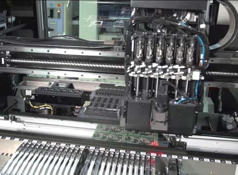
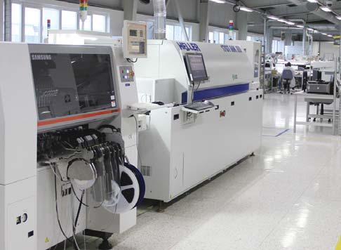
99 R&D overall view Inernal lab MD producion line Cip placing Producion all Tesing 99
49.8. Control Relays and Timers. Contents. Product Selection Guide. Timing Relays
 Conrol Relays and Timers.8 Produc Selecion Guide Noes Applies o TRN model only. Applies o TRF model only. The E5-248 is baery powered and has hree programmable rigger funcions. This produc may perform
Mors Smitt Industrial Technology. General purpose relays
 Mors Smi Indusrial Technology General purpose relays Mors Smi Indusrial Technology General purpose relays Mors Smi - Indusrial Technology Mors Smi has been manufacuring relays since 1902. Our wide relay
$ 12 $ 11. Terminal Block Relays (cont d) Interface PCB Relays with Socket. Why customers choose FactoryMation over competitors
 Interface PCB Relays with Socket. Why customers choose FactoryMation over competitors") 92 REAY www.facorymaion.com/relays Terminal Block Relays (con d) $ 12 V D E Feaures: Changeover relay, raed load 6A/230V(ACI) lim DI-rail moun socke wih buil-in ED posiion indicaor Descripion plae Opional
92 REAY www.facorymaion.com/relays Terminal Block Relays (con d) $ 12 V D E Feaures: Changeover relay, raed load 6A/230V(ACI) lim DI-rail moun socke wih buil-in ED posiion indicaor Descripion plae Opional
TECHNICAL CATALOGUE
 ELKO KO EP Ru Russ ssia ia TECHNICAL CATALOGE ELKO EL KO OE EP P kkra rain ine e ELKO EL K EP KO E KO EL K EP Ge Ger y E KO EP Au EL Ausria ELKO EL ELK LK EP Espa ana n~ MO O D DLA LAR R EL ELE E CTR CTR
Monitoring Technique. VARIMETER Current relay BA 9053, MK 9053N
 Monioring Technique VARIMETER Curren relay, MK 9053N 0221540 Your Advanages Prevenive mainenance For beer produciviy Quicker faul locaing Precise and reliable MK 9053N Opions wih Pluggable Terminal Blocks
ENDA ETM442 DIGITAL TIMER
 english Read his documen carefully before using his device. The guaranee will be expired by damaging of he device if you don' aend o he direcions in he user manual. Also we don' accep any compensaions
Electronic timer CT-MVS.12 Multifunctional with 1 c/o contact Data sheet
 Feaures Raed conrol supply volage 24-48 V DC, 24-240 V AC Mulifuncion imer wih 10 iming funcions: ON-delay, OFF-delay wih auxiliary volage, Impulse-ON, Impulse-OFF wih auxiliary volage, Symmerical ON-
T E C H N I C A L C ATA L O G U E ELKO EP
 T E C H N I C A L C ATA L O G E MODLAR ELECTRIC DEVICE ELKO EP Russia ELKO EP Poland ELKO ELK O EP EP Ger Gerany any E LKO E P ELKO EP ELKO EP lovakia ELKO EP Hungary ELKO EP Roania ELKO EP kraine ELKO
Time Control Technique
 Time Conrol Technique muliimer Mulifuncion Relay MK 785N/2 23928 Your Advanages Up o 1 funcions in one uni Simplified sorage Increased flexibiliy Quick seing of long ime values Opions wih Pluggable Terminal
100% electricity. Modular time relays TM series
 100% elecriciy Modular ime relays TM series Modular ime relays crew fixing faciliy arge cable enries OVATO Elecric exends he range of elecronic ime relays wih new modular models of he TM series, line.
Time Control Technique
 Time Conrol Technique MULTITIMER Mulifuncion Relay MK 785N/2 23928 Your Advanages Up o 1 funcions in one uni Simplified sorage Increased flexibiliy Quick seing of long ime values Circui Diagrams B1 22
Solid-State Time Relays
 Solid-Sae Time Relays 3RP10 and 3RP15 SIRIUS 3R Overview Solid-Sae Time Relays SIRIUS 3RP10 ime relay, assembly widh 45 mm LED o indicae ime relay energized (lef) Accessories Se of coding plugs for seing
Monitoring Technique. VARIMETER Current Relay BA 9053, MK 9053N
 Monioring Technique VARIMETER Curren Relay, MK 9053N 0221540 Your Advanages Prevenive mainenance For beer produciviy Quicker faul locaing Precise and reliable Circui Diagrams A1 i A2 k A1 11 12 14 22 A1
MODULAR TIME RELAYS PLUG-IN AND FLUSH-MOUNT TIME
 Page -2 MOULR TM RLY uiable for consumer swichboards elecable ime ranges on fron:. second - days L indicaion Mouning on mm N rail crew erminals. Page - PLU-N N LU-MOUNT TM RLY, XMM lush and inernal panel
The ramp is normally enabled but can be selectively disabled by suitable wiring to an external switch.
 Vickers Amplifier Cards Power Amplifiers for Proporional Valves EEA-PAM-56*-A-14 Design EEA-PAM-561-A-14 for use wih valve ypes: KDG5V-5, * and KDG5V-7, 1* series EEA-PAM-568-A-14 for use wih valve ypes:
Monitoring Relays. Current Monitoring A A DIN. Comat products comply with different international standards and are certified accordingly.
 Monioring elays Curren Monioring DI Coma producs comply wih differen inernaion sandas and are cerified accoingly. Curren Monioring elays EOC- EUC-B -05-30 -60 JUST LOOP IT LOD Seing ranges x x 3x 4x 5x
Medium voltage power supplies
 Medium volage power supplies Design example 2000 V / 6 Funcion Te recified line volage mainains a square wave generaor of consan frequency, wose AC volage is ransformed, recified and filered, producing
Solid-state Multi-functional Timer
 Solid-sae Muli-funcional Timer Eigh operaing modes (H3DE-M) and four operaing modes (H3DE-S) cover a wide range of applicaions. Programmable conac enables he building of a self-holding relay circui (-
700 FS H 3 U U FS A 3 A U23
 Bullein -F Produc Overview/Produc elecion Bullein -F High Performance Timing Relay Adjusable funcion and iming range iming relays DIN Rail mouned wihou cos of socke. mm wide muli-funcion or single funcions
Connection. Input II EEx ia IIC without SC red. Composition
 Sandsill conroller Oupu: relay Connecion Inpu I EEx ia IIC Inpu II EEx ia IIC 1-channel Conrol circui EEx ia IIC Addiional inpu or roaion direcion deecion or sar-up override 2 relay oupus Inpu requency
Electronic step-on step-off relays SR-2
 Elecronic sep-on sep-off relays - 7 7 7-0min z A 0Va / WI MADE BY COMAT 0 z A 0Va -K / WI MADE BY COMAT 0 Elecronic sep-on sep-off relays ype - wih he following characerisics: Plug in sep-on sep-off relay
Contents DILET, ETR timing relay
 ETR iming relay There s a cerain energy a Eaon. I s he power of uniing some of he world s mos respeced names o build a brand you can rus o mee your every power managemen need. The energy creaed suppors
Technical Catalogue. Relays. Timer Relays Monitoring Relays Motor Protection Relays
 Technical Caalogue Relays Timer Relays Monioring Relays Moor Proecion Relays Relays Conens Elecronic ime relays, Series C 560... 5 Selecion, echnical daa, ordering deails... 6 Funcion able, device wiring
Universal microprocessor-based ON/OFF and P programmable controller MS8122A MS8122B
 COMPETENCE IN MEASUREMENT Universal microprocessor-based ON/OFF and P programmable conroller MS8122A MS8122B TECHNICAL DESCRIPTION AND INSTRUCTION FOR USE PLOVDIV 2003 1 I. TECHNICAL DATA Analog inpus
Electric amplifiers. Table of contents. Features. RE 30095/04.11 Replaces: Types VT 5005 to VT Component series 1X 1/8
 Elecric amplifiers RE 30095/04. Replaces: 05.0 /8 Types VT 5005 o VT 5008 Componen series X 558_d Table of conens Conens Page eaures Ordering code uncional descripion Block diagram / pinou: VT 5005 and
Retro-reflective photoelectric sensors with polarization filter. Dimensioned drawing
 Rero-reflecive phooelecric sensors wih polarizaion filer Dimensioned drawing en 10-2011/04 50105364 1 khz 0 5m We reserve he righ o make changes DS_PRK3B_Sandard_EL_en.fm 10-30 V DC A 2 LS Polarized rero-reflecive
Installation and Operating Instructions for ROBA -brake-checker Typ
 (B.018102.EN) Guidelines on he Declaraion of Conformiy A conformiy evaluaion has been carried ou for he produc in erms of he EC Low Volage Direcive 2006/95/ EC and EMC Direcive 2004/108/EC. The Declaraion
COMBITRON Program Schedule
 OMBITRO Program Schedule OMBITRO are supply and acuaor modules for he elecromagne cluches and brakes. As power supply for D- or A-side swiching differen single-wave and bridge recifiers as well as rapid
Retro-reflective photoelectric sensors with polarization filter. Dimensioned drawing
 Rero-reflecive phooelecric sensors wih polarizaion filer Dimensioned drawing en 10-2011/04 50105364 1 khz 0 5m We reserve he righ o make changes DS_PRK3B_Sandard_EL_en.fm 10-30 V DC A 2 LS Polarized rero-reflecive
Solid-state Timer H3CT
 Solid-sae Timer H3CT DIN 48 x 48-mm Sandard Size Analog Timer Wide ime range (for 4 series of models); 0.1 s o 30 hrs. Wih H3CT-8H models, he oupu ype can be swiched beween ime limi DPDT and ime limi SPDT
TIMERS SELECTION GUIDE
 MONTH MONTH TIMER ELECTION GIDE Timing Chars. ON Delay. Inerval ON. Rising Edge One ho. Asymmeric Repea Cycle OFF. ardela ar Relay. ignal ON Delay. Inerval ON / OFF Delay wih Rerigger. Rising Edge wih
Dimensions. Model Number. Electrical connection emitter. Features. Electrical connection receiver. Product information. Indicators/operating means
 OBE-R-SE Dimensions.8.8 ø..75 7.5 6. 5 6.7 4.9 4. 5.9 ø.6 Model Number OBE-R-SE Elecrical connecion emier Thru-beam sensor wih m fixed cable Feaures 45 cable oule for maximum mouning freedom under exremely
Power Amplifier EEA-PAM-5**-A-32 for Proportional Control Valves Contents The following power amplifier models are covered in this catalog
 Vickers Accessories Power Amplifier EEA-PAM-5**-A-32 for Proporional Conrol Valves Conens The following power amplifier models are covered in his caalog Power Amplifier EEA-PAM-513-A-32 EEA-PAM-523-A-32
Dimensions. Transmitter Receiver ø2.6. Electrical connection. Transmitter +UB 0 V. Emitter selection. = Light on = Dark on
 OBE-R-SE Dimensions Transmier.. 7.5 9..5.8 4.9 4 5 M 8.9 7.5 9..5.8 4 5 M 8.9 ø.6 ø.6 Model Number OBE-R-SE Thru-beam sensor wih m fixed cable Elecrical connecion Transmier Feaures BN +UB WH IN Ulra-small
H3CR. Multifunctional Timer Twin Timer Star-delta Timer Power OFF-delay Timer H3CR-A H3CR-AS H3CR-AP H3CR-A8 H3CR-A8S H3CR-A8E H3CR-G.
 Solid-sae Timer H3CR Please read and undersand his caalog before purchasing he producs. Please consul your OMR represenaive if you have any quesions or commens. Refer o Warrany and Applicaion Consideraions
Dimensions. Transmitter Receiver ø2.6. Electrical connection. Transmitter +UB 0 V. Emitter selection. = Light on = Dark on
 OBE-R-SE Dimensions Transmier.. 7.5 9..5.8 4.9 4 5 M 8.9 7.5 9..5.8 4 5 M 8.9 ø.6 ø.6 Model Number OBE-R-SE Thru-beam sensor wih m fixed cable Elecrical connecion Transmier Feaures BN +UB WH IN Ulra-small
Trigger high-speed, retro-reflective sensors for bottles. Dimensioned drawing
 Trigger high-speed, rero-reflecive sensors for boles Dimensioned drawing en 03-2014/10 50121192-02 10-30 V DC 0 3.6m 5 khz We reserve he righ o make changes DS_PRK18BFX_en_50121192_02.fm Trigger high-speed,
Laser retro-reflective photoelectric sensor with polarisation filter. Dimensioned drawing
 Specificaions and descripion PRKL 3B Laser rero-reflecive phooelecric sensor wih polarisaion filer Dimensioned drawing en 08-2011/04 50105363 2 khz 0 3m 10-30 V DC Polarized rero-reflecive phooelecric
General data 8/91. Overview
 SIRIUS 3RS0, 3RS, 3RS0, 3RS Temperaure Monioring Relays General daa Overview Temperaure seing LED "Device on volage" LED "Relay swiched" Hyseresis swich NSB0_04a LED for display "Up and Down" keys Roary
Siemens AG Overview Expansion module for the LOGO! basic versions For communication between the LOGO! master and external EIB components via EIB
 LOGO! Logic Modules LOGO! CM EIB/KNX communicaion modules Overview Expansion module for he LOGO! basic versions For communicaion beween he LOGO! maser and exernal EIB componens via EIB LOGO! CM EIB/KNX
Retro-reflective photoelectric sensor with polarization filter for bottles. Dimensioned drawing
 Specificaions and descripion PRK 55 Rero-reflecive phooelecric sensor wih polarizaion filer for boles Dimensioned drawing en 05-2012/11 50112987-01 1 khz 0 3.5m 10-30 V DC We reserve he righ o make changes
Laser retro-reflective photoelectric sensor with polarization filter. Dimensioned drawing
 Specificaions and descripion PRKL 3B Laser rero-reflecive phooelecric sensor wih polarizaion filer Dimensioned drawing en 11-2016/01 50105363-02 2 khz 0 3m 10-30 V DC We reserve he righ o make changes
Retro-reflective photoelectric sensors with polarization filter for bottles. Dimensioned drawing
 Rero-reflecive phooelecric sensors wih polarizaion filer for boles Dimensioned drawing en 05-2013/08 50103461 1 khz 0 3.5m 10-30 V DC We reserve he righ o make changes DS_PRK3B42_en_50103461.fm Polarized
Photo-electric detectors
 Phoo-elecric deecors Osiris specific applicaion deecors, mechanical handling series d.c. supply. Solid sae oupu pages /8 o / References, characerisics Compac design Sysem hru-beam Reflex Diffuse Diffuse
Zelio Plug-In Relays. RPM power range. Catalog
 Zelio Plug-In Relays RPM power range Caalog 0 Conens Zelio Plug-In Relays bbinroducion.... bbspecificaions.................................................... 6 bbreferences... bbdimensions.... 0 bbwiring
Retro-reflective photoelectric sensor for foils. Dimensioned drawing
 Specificaions and descripion RKR 53 Rero-reflecive phooelecric sensor for foils Dimensioned drawing en 04-2012/06 50108252-01 1 khz 0 1.8m 10-30 V DC We reserve he righ o make changes DS_RKR53642_en_50108252-01.fm
Valve amplifiers for proportional pressure valves
 Valve amplifiers for proporional pressure valves Type VT-VSPA-, VT-VSPAK- RE 30 Ediion: 03- Replaces: 0.0 Componen series X Suiable for he conrol of all direc and pilo operaed proporional pressure valves
Laser retro-reflective photoelectric sensor with polarisation filter. Dimensioned drawing. Teach button Optical axis Indicator diode
 Specificaions and descripion Leuze elecronic Laser rero-reflecive phooelecric sensor wih polarisaion filer Dimensioned drawing Par No. 501 06860 2 khz 0 3m 10-30 V DC Polarised, laser rero-reflecive phooelecric
Model Number Structure
 Solid-sae Muli-funcional Timer H3CR-A Timers DIN 48 x 48-mm Sae-of-he-ar Mulifuncional Timer A wider power range reduces he number of imer models kep in sock. A wide range of applicaions hrough six or
Laser retro-reflective photoelectric sensor with polarization filter. Dimensioned drawing
 Specificaions and descripion PRKL 3B Laser rero-reflecive phooelecric sensor wih polarizaion filer Dimensioned drawing en 09-2012/06 50105363 2 khz 0 3m 10-30 V DC We reserve he righ o make changes DS_PRKL3B622_en_50105363.fm
Programmable DC Electronic Loads 8600 Series
 Daa Shee Programmable DC Elecronic Loads The programmable DC elecronic loads provide he performance of modular sysem DC elecronic loads in a compac benchop form facor. Wih fas ransien operaion speeds and
Sensing method Application Appearance Sensing distance Model Convergent-reflective Small type 30±3 mm
 Auhorised Disribuors:- AS & AAIN INDIA PV D S-, F.I.E.E., Okhla Indusrial Area, Phase-ii, New Delhi-(India) el : -9 Fax : -9 E-mail : sales@ashalain.com Compac ead Amplifier-separaed Phooelecric Sensor
Time Relays and Dimmers Pulsar T+ / DIM
 GE Indusrial oluions Time Relays and Dimmers Pulsar T+ / DI New ex.geindusrial.com Time Relays / Dimmers Time Relays 4 Performances and feaures 8 Order codes 10 Technical daa Dimmers 6 Performaces and
Programmable DC Electronic Load 8600 Series
 Daa Shee Programmable DC Elecronic Load The programmable DC elecronic loads provide he performance of modular sysem DC elecronic loads in a compac benchop form facor. Wih fas ransien operaion speeds and
Flow Switch LABO-RR.-032-S. Characteristics. Technical data. Ranges
 Flow Swich LABO-RR.032-S Simple and economical flow meer for piping diameers from 32 mm o 150 mm Made from plasic (opionally sainless seel) Wih apping sleeve fixing for very rapid insallaion Rero-fiing
Multicolor contrast sensor. Dimensioned drawing
 Mulicolor conras sensor Dimensioned drawing en 01-2016/06 50133231 12-30 V DC 15 khz 13mm We reserve he righ o make changes DS 2_en_50133231.fm Easy o adjus hrough display of he signal srengh on he device
DISCONTINUED MODEL Replaced with Model JPS3
 Plug-in Signal Condiioners M-UNIT PUSE ADDER (field-programmable) MODE MODE & SUFFIX CODE SEECTI MODE A : Dry conac B :Volage pulse (Specify sensiiviy) C : V pulse (sensiiviy V) D : V/V pulse (sensiiviy
H3DS. Solid-state Multi-functional Timer. Ordering Information. DIN Track Mounted, Standard 17.5-mm Width Timer Range
 Solid-sae Muli-funcional Timer DIN Track Mouned, Sandard 17.5-mm Widh Timer Range A wide AC/DC power supply range (24 o 230 VAC/ 24 o 48 VDC) reduces he number of imer models kep in sock. Eigh operaing
 RE1-LC (Off-delay)")
MCR-S-...-DCI. Current transducer up to 55 A, programmable and configurable. Data sheet _en_11. 1 Description
 Curren ransducer up o 55 A, programmable and configurable Daa shee 100241_en_11 PHOENIX CONTACT 2012-06-07 1 Descripion The MCR-S-...-DCI curren ransducers offer users he opion of ordering a preconfigured
Retro-reflective photoelectric sensor with polarization filter for bottles. Dimensioned drawing
 Specificaions and descripion PRK 53 Rero-reflecive phooelecric sensor wih polarizaion filer for boles Dimensioned drawing en 04-2012/06 50112986-01 1 khz 0 3.5m 10-30 V DC We reserve he righ o make changes
H3CR. Multifunctional Timer Twin Timer Star-delta Timer Power OFF-delay Timer H3CR-A H3CR-AS H3CR-AP H3CR-A8 H3CR-A8S H3CR-A8E H3CR-G H3CR-G8EL
 Solid-sae Timer H3CR Please read and undersand his caalog before purchasing he producs. Please consul your OMRON represenaive if you have any quesions or commens. Refer o Warrany and Applicaion Consideraions
Programmable DC Electronic Loads 8600 Series
 Daa Shee Programmable DC Elecronic Loads 99 Washingon Sree Melrose, MA 02176 Phone 781-665-1400 Toll Free 1-800-517-8431 Visi us a www.tesequipmendepo.com 2U half-rack 3U 6U USB RS232 GPIB The programmable
Solid-state Timer H3CR
 Solid-sae Timer H3CR DIN 48 x 48-mm Mulifuncional Timer Series Conforms o EN61812-1 and IEC60664-1 4 kv/2 for Low Volage, and EMC Direcives. Approved by UL and CSA. Lloyds/NK approvals. Six-language insrucion
Electrical amplifiers
 Elecrical amplifiers RE 30/0.0 Replaces: 09.05 / Type VT-VSPA- and VT-VSPAK- Componen series X H589_d Table of conens Conens Page Feaures Ordering code Funcional descripion and 3 Block circui diagram /
3 - Zelio Time - timing relays
 /0 - onens 0 - Zelio ime - iming relays Selecion guide for Zelio ime - iming relays.................... page /2 # Modular relays, solid sae oupu, widh 17.5 mm................. page /6 # Indusrial relays,
GTZ 25 / 40 / 55. TECHNICAL DATA General features. Category of use: AC51, AC53a
 GTZ 25 / 40 / 55 THEE-PHASE SOLID STATE ELAYS WITH LOGIC CONTOL Main applicaions Thermoforming Plasic exrusion lines Indusrial ovens and furnaces Hea reamens Conrol applicaions wih high swiching speed
Development of Temporary Ground Wire Detection Device
 Inernaional Journal of Smar Grid and Clean Energy Developmen of Temporary Ground Wire Deecion Device Jing Jiang* and Tao Yu a Elecric Power College, Souh China Universiy of Technology, Guangzhou 5164,
Exactly on time and economic switching timing relays ETR and DIL ET
 Exacly on ime and economic swiching iming relays ETR and DIL ET Tailor-made for every applicaion; all componens feaure he benefis of a series well hough-ou righ down o he fines deail. The iming relays
Installation and User Manual
 MULTIFUCTIO POWER & EERGY MOITOR WITH MODBUS RTU PROTOCAL MODEL : MFM-96 MFM-96 POWER & EERGY MOITOR I n d e x Page l Inroducion & Safey Recommendaions 03 l Technical Specificaions 04-05 l Processing Mehod
Time - timing relays 3
 Selecion guide Zelio ime - iming relays Applicaions Oupu hese iming relays enable simple auomaion cycles o be se up using wired logic. hey can also be used o complemen he funcions of PLs. Solid sae iming
Selection guide Zelio Time - timing relays 0
 Selecion guide Zelio ime - iming relays 0 Applicaions Oupu hese iming relays enable simple auomaion cycles o be se up using wired logic. hey can also be used o complemen he funcions of PLs. Solid sae iming
Electrical connection
 Reference scanner Dimensioned drawing en 02-2014/06 50117040-01 200 500mm Disance on background/reference 10-30 V DC We reserve he righ o make changes DS_HRTR46Bref_en_50117040_01.fm Robus objec deecion
Switch Basics and Applications. Selection Service Speed
 Swich Basics and Applicaions Selecion Service Speed Inroducion Basic Swich Types and Applicaions Swich Funcion - Mechanical Poles and Throws, Mechanical Characerisics Swich Funcion - Elecrical Volage and
General Introduction. These modules present a number of practical advantages to the user.
 General Inroducion In measuremen, posiioning and conrol applicaions, i is necessary o monior and indicae he saus of he machine or insallaion. In order for he signal o be processed by he programmable conroller,
ECMA st Edition / June Near Field Communication Wired Interface (NFC-WI)
") ECMA-373 1 s Ediion / June 2006 Near Field Communicaion Wired Inerface (NFC-WI) Sandard ECMA-373 1 s Ediion / June 2006 Near Field Communicaion Wired Inerface (NFC-WI) Ecma Inernaional Rue du Rhône 114
ECMA-373 1 s Ediion / June 2006 Near Field Communicaion Wired Inerface (NFC-WI) Sandard ECMA-373 1 s Ediion / June 2006 Near Field Communicaion Wired Inerface (NFC-WI) Ecma Inernaional Rue du Rhône 114
ROOM THERMOSTAT WITH GSM MODULE
 ROOM THERMOSTAT WITH GSM MODULE Backli display Afer you press any buon, he display is backli auomaically for a leas 5 s. PT32 GST A sophisicaed hermosa which can be remoely conrolled by means of SMS messages
Control circuit for a Self-Oscillating Power Supply (SOPS) TDA8385
 TDA8385") FEATURES Bandgap reference generaor Slow-sar circuiry Low-loss peak curren sensing Over-volage proecion Hyseresis conrolled sand-by funcion Error amplifier wih gain seing Programmable ransfer characer
FEATURES Bandgap reference generaor Slow-sar circuiry Low-loss peak curren sensing Over-volage proecion Hyseresis conrolled sand-by funcion Error amplifier wih gain seing Programmable ransfer characer
MODEL: M6NXF1. POWER INPUT DC Power R: 24 V DC
 Screw Terminal Ulra-Slim Signal Condiioners M6N Series FUNCTION MODULE (PC programmable) Funcions & Feaures Single inpu filer and funcion module 12 ypes of funcions are PC programmable 7.5-mm wide ulra-slim
 Disribued by: www.jameco.com 1-800-831-4242 The conen and copyrighs of he aached maerial are he propery of is owner. 16K-Bi CMOS PARALLEL E 2 PROM FEATURES Fas Read Access Times: 200 ns Low Power CMOS
MODEL: M8PP1. [4] OUTPUT PULSE WIDTH 1: Equal to the input 2: One-shot output (std. pulse width 50 ms) Specify when optional pulse width is required.
![MODEL: M8PP1. [4] OUTPUT PULSE WIDTH 1: Equal to the input 2: One-shot output (std. pulse width 50 ms) Specify when optional pulse width is required.](/thumbs/89/98758644.jpg "MODEL: M8PP1. [4] OUTPUT PULSE WIDTH 1: Equal to the input 2: One-shot output (std. pulse width 50 ms) Specify when optional pulse width is required.") MODE: M8PP1 Dual Oupu Super-mini Signal ondiioners Pico-M Series Max. 50 kz for volage pulse inpu PUSE ISOTOR (buil-in exciaion, E) Funcions & Feaures mplifying, waveshaping a pulse rae inpu and providing
MODE: M8PP1 Dual Oupu Super-mini Signal ondiioners Pico-M Series Max. 50 kz for volage pulse inpu PUSE ISOTOR (buil-in exciaion, E) Funcions & Feaures mplifying, waveshaping a pulse rae inpu and providing
Explanation of Maximum Ratings and Characteristics for Thyristors
 8 Explanaion of Maximum Raings and Characerisics for Thyrisors Inroducion Daa shees for s and riacs give vial informaion regarding maximum raings and characerisics of hyrisors. If he maximum raings of
NEW. Railway applications. Especially manufactured for applications in rail-bound vehicles EN standard NF F /102
 NW ailway applicaions specially manufacured for applicaions in rail-bound vehicles N 50155 sandard NF F 16-101/102 COMAT AG BNT.4 CH-3076 WOB Tel: 41(0)31 838 55 77 www.coma.ch info@coma.ch Fax: 41(0)31
RESISTRON RES-445. Operating Instructions. Important features
 RESISTRON GB Operaing Insrucions Imporan feaures Microprocessor echnology LC display (green), 4 lines, 2 characers, (mulilingual) Alernaively: VF display (blue), 4 lines, 2 characers, (mulilingual) Auomaic
Solid-state Timer. DIN 48 x 48-mm Multifunctional Timer with Many Time Ranges and Operating Modes, and Wide Power Supply Ranges
 Solid-sae Timer DIN 48 x 48-mm Mulifuncional Timer wih Many Time Ranges and Operaing Modes, and Wide Supply Ranges A wider power range reduces he number of imer models kep in sock. An 11-pin or 8-pin model
Ethernet system for length measurement, 24-bit 16/8/4 inductive transducers, LVDT, Half-Bridge, Mahr
 CH0 CH1 CH2 CH3 CH4 CH5 CH6 CH7 CH CH9 CH10 CH11 CH12 CH13 CH14 CH15 Couner 0 Couner 1 Couner 2 Couner 3 sysem for lengh measuremen, 24-bi //4 inducive ransducers,, Half-Bridge, Mahr New! 32 digial I/O
Application & Guidance Notes
 Phooelecric Swiches Applicaions Successful applicaion of phoo-elecrics ino sysems need no involve a deep undersanding of heir principles of operaion. Following hese few simple rules will enable many of
MODEL: M6SXF1. POWER INPUT DC Power R: 24 V DC
 Tension-Clamp Ulra-Slim Signal Condiioners M6S Series FUNCTION MODULE (PC programmable) Funcions & Feaures Mainenance-free ension clamp connecion Single inpu filer and funcion module 12 ypes of funcions
PRM and VTM Parallel Array Operation
 APPLICATION NOTE AN:002 M and V Parallel Array Operaion Joe Aguilar VI Chip Applicaions Engineering Conens Page Inroducion 1 High-Level Guidelines 1 Sizing he Resisor 4 Arrays of Six or More Ms 5 Sysem
Model Number Structure
 Solid-sae Muli-funcional Timers CSM DS_E_5_1 Muliple Operaing Modes and Muliple Time Ranges. DIN 48 x 48-mm Mulifuncional Timer wih Wide AC/DC Supply Range for Boh High and Low Volages. A wide AC/DC power
OPERATION MANUAL. Indoor unit for air to water heat pump system and options EKHBRD011ADV1 EKHBRD014ADV1 EKHBRD016ADV1
 OPERAION MANUAL Indoor uni for air o waer hea pump sysem and opions EKHBRD011ADV1 EKHBRD014ADV1 EKHBRD016ADV1 EKHBRD011ADY1 EKHBRD014ADY1 EKHBRD016ADY1 EKHBRD011ADV1+Y1 EKHBRD014ADV1+Y1 EKHBRD016ADV1+Y1
Intelligent Interface Modules
 General Inroducion In measuremen, posiioning and conrol applicaions, i is necessary o monior and indicae he saus of he machine or insallaion. In order for he signal o be processed by he programmable conroller,
Zelio Plug-In Relays. RUM universal range. Catalog
 Zelio Plug-In Relays RM universal range Caalog 0 Couresy of Seven Engineering, Inc. - (00) -00 - sales@seveneng.com - www.sevenengineering.com Couresy of Seven Engineering, Inc. - (00) -00 - sales@seveneng.com
PSI 9000 WR Series. High Efficiency Programmable DC Power Sources. 3.3 kw to 15 kw THE POWER TEST EXPERTS.
 PSI 9000 WR Series 3.3 kw o 15 kw High Efficiency Programmable DC Power Sources THE POWER TEST EXPERTS PSI 9000 WR Series 3.3 kw o 15 kw Produc Overview The microprocessor conrolled high efficiency laboraory
CR DIN-Relays. Interface modules CR 7. Recommended application 6/5A 3A 2A 1A. 1mA. 2x 1. 3x 1 1 CR16... C C103.06
 CC/...V 4 0 µ0mv... 5Va/0VD Ag/Au-plaed signal relay 3 6A 50VA C6A.. /...V X= 3 3 00µ00mV... 3A 50Va/30VD 0,40VDmax C3A/...V 3 3 4 00µ00mV... 3A 50Va/30VD 0,40VDmax C33A/...V 3 o max 6A A 0-40VA 0A, 50Va
RESISTRON RES-430. Operating Instructions. Important features
 RESISTRON Operaing Insrucions Imporan feaures Microprocessor echnology LC display (green), 4 lines, 2 characers (mulilingual) Auomaic zero calibraion (AUTOCAL) Auomaic opimizaion (AUTOTUNE) Auomaic phase
Model Number Structure
 Solid-sae Muli-funcional Timers CSM DS_E_6_ Muliple Operaing Modes and Muliple Time Ranges. DIN 48 x 48-mm Mulifuncional Timer wih Wide AC/DC Supply Range for Boh High and Low Volages. A wide AC/DC power
ACTIVE INTERFACE TECHNOLOGY
 General Inroducion In measuremen, posiioning and conrol applicaions, i is necessary o monior and indicae he saus of he machine or insallaion. In order for he signal o be processed by he programmable conroller,
OPS Solar Inverter Specification & Manual
 Solar Inverer Specificaion & Manual Conens 1 FEATURES... 2 2 TECHNICAL SPECIFICATION... 4 3 APPLICATION... 7 3.1 LED DISPLAY STATUS... 7 3.2 POWER SAVING MODE... 8 3.3 OUTPUT FREQUENCY SETTING... 8 3.4
White paper. RC223 (type B) residual-current release
 residual-current release") Whie paper (ype B) residual-curren release (ype B) residual curren release Index 1. Generals... 2 2. Applicaion descripion... 3 2.1 Applicaions...3 2.2 Applicaion examples...4 2.3 How does an operae?...6
Whie paper (ype B) residual-curren release (ype B) residual curren release Index 1. Generals... 2 2. Applicaion descripion... 3 2.1 Applicaions...3 2.2 Applicaion examples...4 2.3 How does an operae?...6