DragonLink V3 Advanced Complete System. DragonLink OSD DRAFT ONLY. User Guide v0.3 Sep Applicable versions:
|
|
|
- Norma McDowell
- 5 years ago
- Views:
Transcription


1 DragonLink V3 Advanced Complete System DragonLink OSD DRAFT ONLY User Guide v0.3 Sep 2018 Applicable versions: UI: , RX/TX: 18 April 2018, OSD: P age
2 Table of Contents 1 Introduction Overview Package Contents Specifications Software Updates Changelog Known Issues and Limitations Product Support Warnings and Safety 8 2 Software Installation Minimum System Requirements Obtaining the Latest Software / Firmware Software Installation Applying Firmware Updates 13 3 Configuration DragonLink GUI DragonLink Transmitter General Settings Channel Mixing / Assignment Power Settings RF Settings Alarms and Sounds Presets External Connections SD Logging RSSI Telemetry Info Spectrum Analyzer DragonLink Transmitter Using Menu Button Range Test Bind Mode Servo Test Change Transmitter ID Exit USB Telemetry Mode 32 2 P age
3 3.3.6 Set Failsafe Channel Positions DragonLink Receiver (via Transmitter) RX Failsafe Behaviour Channel Assignment (RX Outputs) DragonLink Receiver Receiver Outputs General Settings Radio Modem GPS Settings Log Information RSSI Spectrum Analyzer Stabilization 43 4 Installation DragonLink Transmitter DragonLink Nano Receiver DragonLink Micro Receiver DragonLink High-Power Receiver 49 5 DragonLink V3 with Futaba 14SG Transmitter Futaba 14SG Configuration DragonLink RX / Vector Hardware Connections Hardware Connections for DragonLink TX with Futaba 14SG Configure DragonLink TX for use with Futaba 14SG DragonLink V3 with EagleTree Vector Flight Controller 52 EXAMPLE #1 12 Channels, Analog RSSI, and Telemetry connected to the DL RX Servo Rail 52 Transmitter Channels: 52 DL RX Pins (PWM Output) Sbus Output (to Vector) 53 Connections 53 Settings 54 Dragonlink TX 54 Dragonlink RX 56 Vector Settings 57 Setup the Vector UART for Telemetry 60 EXAMPLE #2 12 Channels, Digital RSSI, and Telemetry connected to the DL RX UEXP 63 3 Page
4 Transmitter Channels: 63 DL RX Pins (PWM Output) Sbus Output (to Vector) 63 Connections 63 Settings 64 Dragonlink TX 64 Dragonlink RX 66 Vector Settings 67 8 Pixhawk Dragonlink V3 Configuration 71 4 P age
5 1 Introduction 1.1 Overview The DragonLink V3 System has been constructed from the best performing, highest quality components, using the latest and most advanced technology available. This system is built to outperform everything else on market and will last for many years. It is not cheap, but it will be the best FPV investment you will make. Some of the DragonLink V3 features include: Typical range of more than 60 KM with stock antennas Full bi-directional telemetry - telemetry range varies with receiver type and data rate used Built in serial radio modem Full MavLink support, works with Tower, Mission Planner, and others Built in Bluetooth for display of telemetry on any android Smartphone or Tablet Fully configurable using PC software Can serve as a lost plane finder using optional GPS hardware and a telemetrycompatible controller Easy-to-see multi-color LEDs for instant status monitoring Audible alarms (for low voltage, low RSSI, etc.) Logging of flight, position, etc. to Micro-SD card (in development) RF Spectrum Analyzer Super-fast update rates available for racers and obstacle flyers Hassle free, bind-and-fly operation for those that want a basic experience Fully compatible with existing Dragon Link Micro Receivers (full bi-directional) The Dragon Link complete system is proudly made in the USA, and is fully guaranteed in the USA. The system includes everything you need for long range, high performance RC control, and there is nothing additional to purchase. To get started with the best RC control money can buy, just order a complete DragonLink system and choose the correct options for your RC transmitter connection cables and airplane antenna options to suit. NOTE: FPV video transmission is not a function of the DragonLink System and will require the purchase of additional equipment. 5 P age
6 1.2 Package Contents DragonLink V3 Advanced Complete System package contents include: 1x Long Range V3 Advanced Slim Transmitter 1x Long Range Receiver (Micro or Advanced) 1x Genuine Nagoya Transmitter Antenna 1x High Performance FPVPro Receiver Antenna 1x Connection Cable for Transmitter Module (type included according to selection made at time of purchase) This user guide also covers the use of the following optional DragonLink products: DragonLink Transmitter (non-slim) DragonLink Advanced (high-power) Receiver DragonLink 100 amp Current Sensor DragonLink high-accuracy GPS position sensor DragonLink Micro OSD 1.3 Specifications DragonLink V3 Advanced Transmitter (Slim) Input Voltage 5 18v (2 4 cell LiPo) Operating Frequency 433MHz (frequency hopping in ARS band) Typical Range 40km (using supplied antennas) Weight 90g Length 79mm Width 60mm Thickness 15mm DragonLink V3 Advanced Transmitter Input Voltage 5 18v (2 4 cell LiPo) Operating Frequency 433MHz (frequency hopping in ARS band) Typical Range 40km (using supplied antennas) Weight 150g Length 86mm Width 75mm Thickness 30mm DragonLink V3 Micro Receiver Input Voltage 5 9v (UBEC or 2 cell LiPo) Operating Frequency 433MHz (frequency hopping in ARS band) 6 P age
7 Transmit Power Weight Length Width Thickness 25mW g 52mm (not inc. SMA) 23mm 9mm (14mm inc. pin headers) DragonLink V3 Advanced (high-power) Receiver Input Voltage 5 9v (UBEC or 2 cell LiPo) Operating Frequency 433MHz (frequency hopping in ARS band) Transmit Power 1500mW Weight g Length 70mm (not inc. SMA) Width 36mm Thickness 11mm (14mm inc. pin headers) 1.4 Software Updates For instructions on how to apply software or firmware updates, please see sections 2.3 and 2.4, respectively Changelog NanoRX, no Vector Open Telemetry with UEXP-Port Fixed in latest FW but requires a restore default settings. Problem with parameter fetch with Mavlink from ArduPilot Tests reveal this to be working, most likely a problem with some setups causing overflow in the buffer due to usage of more bandwidth than what's available for an extended period of time when loading parameters. There is no selection for "Auto Detect RX Idle" in the TX GUI. This setting is not needed with new BT-module and will only show with transmitters using the old module. S.Bus data sent between the RC transmitter and the DL transmitter gets compressed. The expected nominal range of 988uS-2012uS changes to 1020uS-1980uS. Fixed. GUI: shows coded/packed GPS data (also written to SD card) Fixed to some degree, the GUI and SD now uses decimal-degrees but unsigned. It should be noted, that the RX shows the coordinates as degrees, decimal minutes. To be fixed in future versions Known Issues and Limitations Voltage sensor not working on UEXP-Port Pin 3 (Nano RX) 7 P age
8 [Elements positioned on the DragonLink OSD within the GUI will not always show the correct location on the FPV video feed. The OSD is still largely under development.] 1.5 Product Support Your Dragon Link system is fully guaranteed and we will be happy to repair, test and upgrade it to the latest firmware free of charge. If you have exhausted the troubleshooting procedures in section [to be added] at the end of this manual and still have no success getting your DragonLink system to work, send your transmitter and receiver ONLY (NO antennas, NO accessories or other items) to us for repair. It is VERY IMPORTANT that you include a note explaining what is wrong so that we can correctly diagnose your system. Also remember to include your full name and return address on the note so that it can be sent back to you. If you are outside the USA, you can use the cheapest way possible to send it to us in a small padded envelope, or very small box to keep the postage cost low. The mail is very reliable and fast in the USA so there is no need to pay extra for express mail, or very expensive tracking. Shipping address: ROSA YSLA PO BOX 388 CORTARO AZ USA Support contact: support@fpvpro.com 1.6 Warnings and Safety The DragonLink system is for hobby use only, in radio-controlled planes, copters, boats, and cars. Use of the system for any other than its intended purpose may cause damage to property, personal injury, or death. Always observe proper use of the DragonLink system and ensure that all appropriate safety measures are taken during use and when setting up (eg. when soldering), in accordance with the user manuals for any other applicable products. Always observe safety precautions for Lithium Polymer and other battery types. Improper use of batteries can cause fires, serious burns, and explosions. Never use or charge a damage or puffed battery. Always observe local and national laws regarding the use of radio transmitters and remotely piloted vehicles. 8 P age
9 DragonLink and FPVPro will not accept any liability for any loss, fines, or damage that may result from the use of this system. 9 P age

10 2 Software Installation This chapter outlines the procedures for installing the DragonLink GUI onto a Microsoft Windows PC and then using the DragonLink GUI to load the latest firmware onto your DragonLink hardware. 2.1 Minimum System Requirements Component Requirement Computer / Processor Pentium 4, Athlon 64, or equivalent Memory (RAM) 2 gigabytes (GB) or greater Operating System Microsoft Windows 7, 8, 8.1, 10 Video Display with resolution 1024x768 or greater Internet Connectivity 256kbit/s or faster recommended 2.2 Obtaining the Latest Software / Firmware It is strongly advisable to check for firmware and software updates regularly as they may include bug fixes, new features, and performance improvements. Before flying your DragonLink system for the first time, it is necessary to apply the latest firmware and obtain the newest version of the DragonLink GUI software for PC. 1. To begin checking for updates, visit this section of the DragonLink website: 2. From there, select your applicable DragonLink system: 3. Then select Complete Systems: 10 P age
 has downloaded, extract it by right-clicking the file and selecting Extract All 2.3 Software Installation 1. The compressed (.")

11 4. Lastly, click on the download link near the top: 5. Once the compressed (.zip) has downloaded, extract it by right-clicking the file and selecting Extract All 2.3 Software Installation 1. The compressed (.zip) file obtained from the DragonLink website contains the following files: NOTE: You will require an internet connection in order to perform the installation as the installer needs to download additional software components. 2. Double-click the DragonLink_GUI_Setup.exe file to begin the installation of the DragonLink software. At the prompt, select Install. 11 P age


12 3. Please wait for the download to complete. 4. Once the installation is complete, the software can be launched from the DragonLink shortcut on the Start Menu. 12 P age

13 2.4 Applying Firmware Updates Firmware updates can be easily applied to your DragonLink transmitter, receiver, or OSD, using the DragonLink GUI software. WARNING: It is important not to interrupt the firmware update process as this has the potential to cause hardware damage and render your device unusable. 1. First, connect your DragonLink transmitter, receiver, or OSD to your PC using a micro- USB cable. Ensure the device tab appears in the DragonLink GUI software. It may take a moment for drivers to install before the tab appears. If it does not appear, please follow the Driver Installation Troubleshooting guide in section [to be added]. 2. Select the relevant tab for the device you wish to update. Then, select the Update page and click Reboot Hardware in firmware update mode 13 P age

14 3. Once the hardware has rebooted you will be presented with the below screen, which offers a number of firmware options. -Select latest beta firmware if you wish to try out the most up-to-date features and / or bug fixes. -Select latest Stable firmware if you wish to use the most up-to-date firmware that is known not to have any major bugs. -Select Select and upload file if you wish to manually specify a firmware file to upload to your device. (This is used in such instances as when you may wish to downgrade to a previous version of firmware.) After selecting one of the options, the software will automatically download the firmware from the internet (or allow you to navigate to the firmware file and select it), then begin applying it to your DragonLink device. NOTE: While every precaution is taken to prevent serious bugs making it into any version of our firmware, it is possible that beta firmware may contain bugs which have the potential to cause the loss of control of your model aircraft. At the time of writing, no such bugs are known to exist, however please proceed with the appropriate level of care as DragonLink cannot accept any responsibility for any damages or the loss of your model aircraft. 14 P age

15 3 Configuration DragonLink GUI NOTE: After changing settings relating to update-rate, bandwidth allocation, use of narrow-band, no. of channels, hardware IDs, or the enabling or disabling bidirectional data, it will be necessary to re-bind your DragonLink transmitter and receiver. Saving Settings Before disconnecting or rebooting your DragonLink device, ensure that any changes to the configuration are not lost by clicking Save Settings at the bottom of the DragonLink GUI window. Some pages have additional save buttons ensure you click these as necessary. 3.1 DragonLink Transmitter General Settings 15 P age
16 ID: This number should be changed to something unique before your DragonLink system is used for the first time. It is used as an identifier to encode the transmission data so the receiver does not suffer interference from other DragonLink systems during flight. Once changed, re-binding with the receiver is necessary. Firmware version: This field displays the version of firmware currently applied to the DragonLink transmitter. Input 1: Specifies the protocol used by the controller to talk to the DragonLink transmitter. This must match the protocol used by the controller s trainer jack or module-bay port. Use model memory: Enables the use of model memory, which allows switching between 3 different saved configuration profiles so that the settings do not need to be adjusted manually each time for use with different model aircraft. When enabled, the desired model can be selected by setting the switch position before powering on the transmitter (Switch Ex3 on large transmitter, or switch Ex1 on the Slim). Once the transmitter is powered on, the switch can then be used normally for other functions without affecting the model selection. Reboot TX: reboots the DragonLink transmitter. Required for some changes to take effect. Reset TX to factory settings: Restores all settings back to factory default. A recommended first-step when troubleshooting the DragonLink system. Bind: Places the DragonLink transmitter in binding mode. To complete the binding process once this mode has been activated: 1 Power on the DragonLink receiver. The receiver s blue and green LEDs should flash alternately, indicating a successful bind. 2 Power off the receiver and reboot the transmitter. 3 The receiver s blue LED should now be lit, indicating a successful link to the DragonLink transmitter. The transmitter s LED(s) will not be lit unless connected to an external power source. Load Model 1 3: These buttons switch between saved model configurations. Before changing to another Model, ensure settings are saved as any unsaved changes will be lost. 16 P age
, to any of the 12 channels on the DragonLink system.")
17 3.1.2 Channel Mixing / Assignment The Channel Mixing settings page allows you to map channels from your controller, as well as the DragonLink transmitter s switches or the rotary pot (large transmitter only), to any of the 12 channels on the DragonLink system. In addition, the sliders to the right of each channel show the position of each channel, live, so you can confirm their functionality without needing the receiver or additional hardware connected. CH 1 12: The drop-down menus on this screen allow you to assign an input to each of the 12 channels that the DragonLink transmitter communicates to the receiver. The available options for each channel include: Channels 1 12 from Input 1 Channels 1 12 from Input 2* Switch 1 (Ex1) Switch 2 (Ex3)* Rotary pot (Ex2)* Voltage 17 P age


18 *not available on DragonLink V3 Slim transmitter NOTE: Configuration of the receiver is also required in order to complete the channel mapping / mixing setup. See chapter 3.5. Assigning voltage to a channel will cause that channel s position to move in conjunction with the DragonLink transmitter s input voltage. This could, for example, be used by the model aircraft to display an indication on the OSD of the transmitter s voltage, or for an RTL mode to be set based on low TX voltage, or for a physical servo to perform some function once the TX battery reaches a certain level. The channel will move from minimum to maximum positions based on a voltage range of approximately 5v 16v Power Settings The DragonLink transmitter s RF output power can be controlled automatically or set to a fixed milli-watt value manually by the user. 18 P age

19 NOTE: Auto mode increases the RF power as-needed in order to maintain a stable RC link and reduces it when not needed to maintain efficiency. It does so very quickly far quicker than the user could adjust it manually and in much finer increments. For this reason, Auto is the recommended mode. Low: sets the transmit power level when the switch, RC channel, or rotary pot is in the lower third of the channel range Mid: sets the transmit power level when the switch, RC channel, or rotary pot is in the middle third of the channel range High: sets the transmit power level when the switch, RC channel, or rotary pot is in the upper third of the channel range Power switch: Defines the switch, RC channel, or rotary pot that will be used to alter the transmit power. At the time of writing, there is no option to remove the assignment of a switch or RC channel to the power setting, however, if the low, mid, and high settings are all set to Auto (or an identical fixed value), the settings on this page will have no effect. In addition, the assignment of a switch or channel here will not prevent it from being assigned to other functions elsewhere RF Settings The RF settings page controls how the DragonLink transmitter talks to the receiver. Changing these settings can affect the control range and telemetry range, as well as the responsiveness of control over the model aircraft. For example, lowering the 19 P age
20 number of channels sent to the receiver will improve the responsiveness, while decreasing the bi-directional bandwidth and lowering the update rate to its minimum setting will greatly increase the range at which telemetry can be received. At the bottom of the page, the approximate update rate (hertz) is displayed, along with the radio modem s uplink and downlink data rates (bytes per second). These values can be used to gauge the effect that changing the settings will have. In real-world usage situations, any gain to be had by lowering the number of transmitted channels or bi-dir bandwidth will be marginal, and may result in compromised performance. Only lower these settings below normal in cases where extreme range and link stability are required. NOTE: MavLink telemetry streams require a relatively high data rate. Without altering the configuration of the flight controller, MavLink typically only works with bidir bandwidth set to High and RF preference set to Fastest update-rate. RF Band: [to be added if you know what this does please PM DangerFlite on RCGroups] Use bi-dir: Enables or disables bi-directional communication between the transmitter and receiver. Disabling this setting will disable all telemetry and radiomodem functionality. Trans. channels: Specifies how many channels to transmit to the receiver. Bidir bandwidth: Specifies how much bandwidth to allocate to bi-directional communication. Maximum value is required for stable MavLink. RF preference: Specifies how rapidly to update the channel positions. Use narrowband: Effectively uses half the normal bandwidth, allowing much tighter internal RF filters for a cleaner signal Alarms and Sounds 20 P age
.")
21 The DragonLink transmitter is capable of providing a range of audible warnings to the user. Missing PPM: Triggered by a loss of input from the radio controller s trainer jack or module bay connection. Low TX voltage: User-configurable low input-voltage alarm. Low flight voltage: Triggered by low voltage reading from optional DragonLink Voltage Sensor (requires active telemetry link). Low RX RSSI: User-configurable low signal strength alarm. Change power level: Either one, two, or three beeps will be played to correspond with the selection of either low, mid, or high power levels, respectively. When using Auto power level modes only, disabling this alert is recommended (see section 4.1.3). Micro Power mode*: Plays a repeating audio reminder while the transmitter is in micro power (range test) mode. Servo test mode*: Plays a repeating audio reminder while the transmitter is in servo test mode. Bind mode*: Plays a repeating audio reminder while the transmitter is in bind mode. * It is recommended that these reminders be enabled to ensure the model aircraft is not inadvertently launched while the transmitter remains in a mode that may cause loss of control or damage. 21 P age
22 3.1.6 Presets The Presets page can be used to apply a range of configuration templates to your DragonLink transmitter. These won t alter general settings, such as channel and switch assignments, model ID, or alarms, however it will alter settings to do with bidirectional data, update rate, and bandwidth in order to optimise performance for the use-case determined by the preset. After applying a preset, it will be necessary to check all of the settings to confirm they are suitable. 22 P age

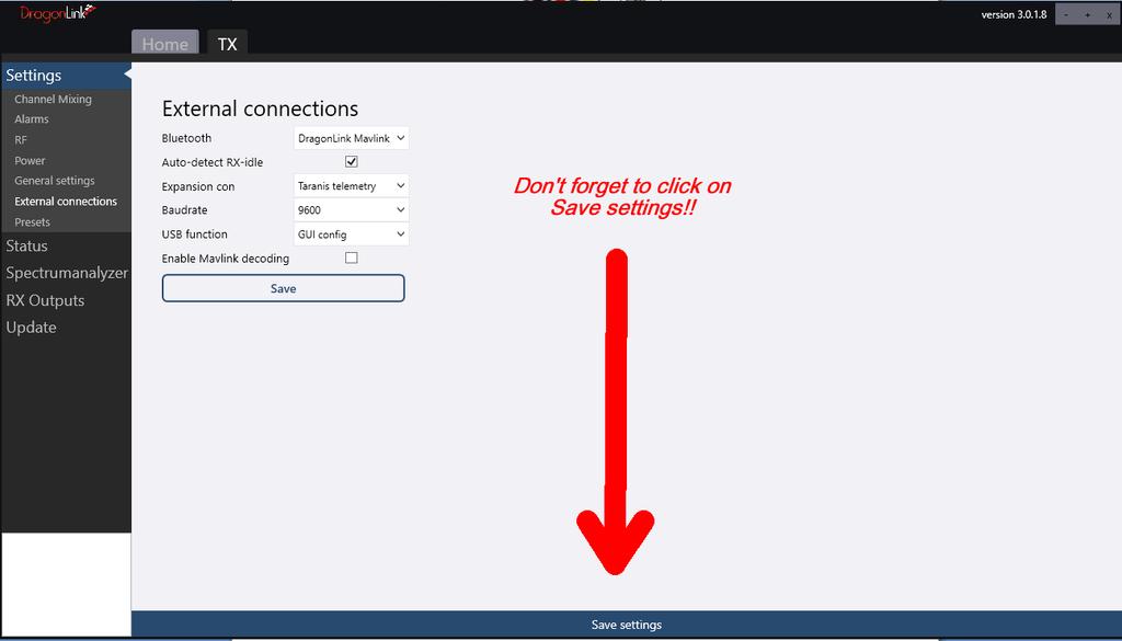
23 3.1.7 External Connections The External Connections page is used to assign functions to the physical and wireless connections on the DragonLink transmitter. NOTE: Chapters [to be added] contain instructions and example configurations for using your DragonLink transmitter to send telemetry for some of the more common flight controller and ground-station setups. Bluetooth (on supported models): Sets the type of data that will be streamed to the Bluetooth virtual COM port. Option Function Radio modem Passes raw serial data directly to and from the connected device. DragonLink Mavlink Encodes non-mavlink telemetry from the aircraft into a MavLink-compatible telemetry stream for use with ground stations. Bi-directional Yes No Auto-detect RX idle: 23 P age
24 NOTE: This issue does not affect newer Slim transmitters with an updated bluetooth module and thus, this setting will not be visible unless it is required by the connected transmitter. When enabled, the DragonLink transmitter looks for data (eg. MavLink heartbeats) coming from the device connected by bluetooth. If the upstream data stops (ie. the bluetooth device is disconnected), downstream telemetry data is no longer sent to the bluetooth connection. This setting is designed to prevent overflow of the bluetooth module s buffer which occurs when data is sent to the module and no device is connected to receive it. When this happens, bluetooth will not work until the DragonLink transmitter has been power-cycled (reset). In order to use receive-only telemetry (ie. with a ground station that does not send any uplink data) this setting should be disabled. In this state, the user should be aware that disconnecting the bluetooth device while the telemetry stream is active will cause the module to crash and require a reset of the DragonLink transmitter. Expansion con: Sets the type of data that will be streamed to the UEXP port on the base of the transmitter. Option Function Radio modem Passes raw serial data directly to and from the connected device. DragonLink Mavlink Encodes non-mavlink telemetry from the aircraft into a MavLink-compatible telemetry stream for use with ground stations. Taranis telemetry Encodes either MavLink or non-mavlink telemetry data into an S.Port telemetry stream for use with a FrSky Taranis controller Bi-directional Yes No No Baud rate: Sets the serial baud rate of the UEXP expansion connector. USB Function: Sets the type of data that will be streamed to the USB virtual COM port. 24 P age
25 WARNING: Changing the USB function setting will prevent the DragonLink GUI from being able to connect to the transmitter for configuration purposes. See section for instructions on how to change this setting back to the default. Option Function Radio Passes raw serial data directly to and from the modem connected device. DragonLink Encodes non-mavlink telemetry from the aircraft Mavlink into a MavLink-compatible telemetry stream for use with ground stations. GUI config Allows the connected device to configure the transmitter using the DragonLink GUI Bi-directional Yes No N/A NOTE: Baud rates do not apply to the USB virtual COM port. As long as the baud rate is correct on the receiver, and the receiving software matches that setting, the data will parse successfully. Enable MavLink decoding: This setting enables decoding of an incoming MavLink telemetry stream so that certain sensor values can be passed to external, non- MavLink devices. 25 P age
. At the time of writing, support for logging is still in development.")
26 3.2.8 SD Logging This page allows you to see diagnostic information regarding the logs that have been saved to the SD card (not included). At the time of writing, support for logging is still in development. 26 P age

27 3.2.9 RSSI On this page, the RSSI (received signal strength indication) is displayed in live graph view, along with the transmitter input voltage. This indication of RSSI represents the strength of the telemetry signal sent from the receiver to the transmitter, and not the strength of the RC signal sent from the transmitter to your model aircraft. 27 P age

28 Telemetry Info When a compatible GPS, voltage sensor, or OSD are connected to the DragonLink receiver and the pin assignments are correctly configured, or when MavLink Decode is used to capture telemetry from a valid MavLink stream, the incoming telemetry data will be visible on this tab for diagnostic purposes. 28 P age

29 Spectrum Analyzer The spectrum analyzer can be used to assess the RF spectrum to look for any unexpected radio interference prior to flight or to diagnose the cause of any radio interference from other components on your model aircraft. The example screenshot above shows an RF noise floor (the signal strength of average background noise) of approximately -120dBm across the 433mHz band ( mHz), which is ideal. It is normal to see a spike on the spectrum analyzer when your DragonLink receiver is powered on and within range. 29 P age
30 WARNING: A noise floor significantly higher than -110dBm indicates a potential issue that may result in reduced range and loss of control over your aircraft, so should be investigated and resolved prior to flying. 3.3 DragonLink Transmitter Using Menu Button The DragonLink transmitter allows for certain functions to be performed using the Menu button on top of the unit Range Test Conducting a range test before each flight is an important step in ensuring that there are no faults, interference, or misconfigurations that could result in the loss of your model aircraft. In range test mode, the RF transmit power is greatly reduced to simulate the effects of extreme range. Range tests should be conducted on-location, with a clear line-of-sight and with environmental conditions matching those of the planned flight. To conduct a range test: 1. Hold down the Menu button on the DragonLink transmitter and turn on the power. 2. After the power-on sound is played, the LED(s) will turn green accompanied by 1 beep. 3. Release the Menu button. 4. The transmitter will continue to play 1 beep (if the range test mode alarm is enabled) and the LED(s) will flash green to indicate it is in range test mode. 5. Position the transmitter with the antenna vertical. 6. Carry the model aircraft away from the transmitter, ensuring that the receiving antenna is also kept in its flight orientation, and monitor the blue LED on the receiver. 7. The receiver s blue LED turning off indicates a temporary loss of signal from the transmitter. Brief flickers are normal during operation even at close range. Once the LED is in an off state approximately 50% of the time, measure the distance from the transmitter to the model aircraft. 8. To exit range test mode, press the menu button. 30 P age
31 In normal conditions, the range test should yield a distance of approximately 10 metres, or 30 feet. 5 metres, or 15 feet, is acceptable for shorter range craft that will operate up to a maximum distance of 5km Bind Mode It is possible to bind the transmitter to the receiver without using the DragonLink GUI. To do so, 1. Ensure the receiver is powered off. 2. Hold down the Menu button on the DragonLink transmitter and turn on the power. 1. After the power-on sound is played, continue to hold the menu button until the LED(s) on the transmitter turn blue accompanied by 2 beeps. 2. Release the Menu button. 3. The transmitter will continue to play 2 beeps (if the bind mode alarm is enabled) and the LED(s) will flash blue to indicate it is in binding mode. 4. Power on the receiver. 5. The receiver s blue and green LEDs should both begin flashing to indicate a successful bind. 6. Power off both the receiver and the transmitter to save the binding Servo Test In servo test mode, the DragonLink transmitter will continuously sweep all channels back and forth from minimum to maximum positions. 1. Hold down the Menu button on the DragonLink transmitter and turn on the power. 2. After the power-on sound is played, continue to hold the menu button until the LED(s) on the transmitter turn yellow accompanied by 3 beeps. 3. Release the Menu button. 4. The transmitter will continue to play 3 beeps (if the servo test mode alarm is enabled) and the LED(s) will flash yellow to indicate it is in servo test mode. 5. To exit servo test mode, press the menu button. 31 P age
32 3.3.4 Change Transmitter ID Before operating the DragonLink system for the first time, the transmitter ID must be changed as not doing so presents the possibility of interference if another system with the default ID is used within range. 1. Hold down the Menu button on the DragonLink transmitter and turn on the power. 2. After the power-on sound is played, continue to hold the menu button until the LED(s) on the transmitter turn red accompanied by 4 beeps. 3. Release the Menu button. 4. The transmitter s LED(s) will flash red to indicate the ID has been changed. 5. To exit ID change mode, you will need to power-cycle the transmitter. NOTE: You will need to re-bind your receiver(s) after changing the transmitter ID Exit USB Telemetry Mode After changing the USB function setting on the DragonLink transmitter, it will no longer be possible to configure the transmitter using the USB port and GUI software. To restore the default USB mode: 1. Hold down the Menu button on the DragonLink transmitter and turn on the power. 2. After the power-on sound is played, continue to hold the menu button until the LED(s) on the transmitter turn white accompanied by 5 beeps. 3. Release the Menu button. 4. The transmitter will play the power up sound and the LED(s) will flash white to indicate the USB mode has been changed. 5. Power-cycle the transmitter for the change to take effect Set Failsafe Channel Positions When the Normal failsafe mode is applied to the DragonLink receiver, it will move all of the channels to a pre-configured position upon loss of signal. 1. With the DragonLink transmitter and receiver powered on, check that both the transmitter and receiver are displaying blue LEDs to indicate an active link. 32 P age

33 2. Press and hold the Menu button until 1 beep is heard and the LED(s) momentarily turn blue-green. 3. The position of all sticks, switches, and rotary pots should now be saved to the receiver. WARNING: Prior to setting the failsafe channel positions, ensure the position of any mode switches, such as arm or return-to-home are in the position you wish them to remain should the R/C link be lost. 3.4 DragonLink Receiver (via Transmitter) 33 P age
34 The DragonLink receiver can be configured using the GUI (to a limited extent) while the DragonLink transmitter is connected to the PC and the receiver is powered on. At this time, it is not possible to configure the PPM / SBUS output, the UEXP port, or to select certain other RX pin assignments through this page. For those items, the PC will need to be directly connected to the receiver. If the fields on this page are blank, settings can be retrieved from the receiver using the Update info button. If this does not work, ensure the receiver is powered on and has been bound to the transmitter. NOTE: Ensure settings are saved on this page using the dedicated Save settings button RX Failsafe Behaviour See section Receiver Outputs subheading Failsafe Channel Assignment (RX Outputs) 34 P age
 receiver, there is a dedicated set of pins (CH 13) for this function. 3.")
35 CH1 X: These drop-down menus allow the assignment of a function to each of the physical pins on the DragonLink receiver. NOTE: Analogue RSSI is only selectable on CH8 of the Micro receiver. On the Advanced (high-power) receiver, there is a dedicated set of pins (CH 13) for this function. 3.5 DragonLink Receiver The first time you connect your DragonLink receiver to the DragonLink GUI, you may be prompted to set the receiver type. Ensure that you select this correctly as an incorrect selection may result in unusable channels. 35 P age
36 3.5.1 Receiver Outputs Failsafe: The failsafe setting determines how the receiver behaves during fail-safe (loss of signal from the DragonLink transmitter). Normal: The receiver s outputs (PPM / SBUS / PWM) remain active and the channels (sticks, switches, etc.) positions will move to saved positions set by the user during failsafe configuration. See section for instructions on setting up and saving these channel positions. No output: The receiver s outputs (PPM / SBUS / PWM) outputs will deactivate when a fail-safe occurs. WARNING: If using Digital RSSI, that value will also no longer be updated until the signal from the transmitter is re-acquired. Keep position: All channels will hold their last-known position until signal is reacquired. WARNING: Where applicable, if using Keep position you may need to ensure that your flight controller is correctly configured to monitor the DragonLink receiver s RSSI value in order for it to correctly identify when a fail-safe event has occurred. Receiver outputs: The Receiver outputs section allows you to assign functions to each of the pin headers on your DragonLink receiver. Pictured below is the configuration page for the Micro receiver, which has 8 multifunction pin headers. In the example below, channel 8 (CH 8) has been assigned to output S-BUS, while the remaining 7 channels output a standard single-channel PWM signal. 36 P age
 or channel 13 (advanced RX).")
37 NOTE: Analog RSSI is only selectable on channel 8 (micro RX) or channel 13 (advanced RX). 37 P age
. The MavLink Decode assignment functions as a Serial input from the flight controller only no output is required as it is not bi-directional.")
38 NOTE: For use with MavLink data, it is possible to select the Serial in and Serial out channel assignments (for bi-directional telemetry and mission planning) or the MavLink Decode assignment (for decoded telemetry only provides maximum range). The MavLink Decode assignment functions as a Serial input from the flight controller only no output is required as it is not bi-directional. An additional 4 channels are visible in the GUI when connected to an Advanced receiver. PPM/S-bus out: These drop-down menus allow you to assign channels to the PPM or S-BUS stream and select the number of channels to include. The maximum number of channels for either protocol is 12. UEXP con pin3/4: These connectors can also be assigned various functions, including S-BUS, PPM, GPS input, Serial communications and OSD data for the DragonLink OSD. NOTE: Some S-BUS devices require a signal with inverted logic. For these devices, select S-BUS inv General Settings 38 P age
.")
39 ID: Displays the Transmitter ID (previously set by you) that the receiver is currently bound to. Firmware version: Displays the version of currently applied firmware. Volt Cal Calue: This value allows calibration of the DragonLink Voltage Sensor (sold separately). If you measure the voltage of your flight battery and discover it to be incorrect, this value, which is a percentage of the sensed voltage, can be adjusted to correct it. Rf Band: Displays the selected RF Band as set on the transmitter prior to binding. Hardware ID: This setting tells the receiver which type of receiver it is and as such it should never need to be changed. This configuration is needed internally for the firmware to handle pin assignments and configuration. This is normally set once when first connected to a PC, however it can be changed here if it is inadvertently set incorrectly. Set hardware ID: Confirms the change to the above setting. Reset hardware to Factory Settings: Restores all of the configuration to factory default settings Radio Modem Input / output baud rate (on receiver): Specifies the baud rate for the Receiver to use for serial radio modem communication. This must match the baud rate set for the device(s) attached to the Receiver and on the receiving ground station. It must also match the Transmitter s UEXP baud rate, if that connection is to be used on the receiving end. 39 P age

40 Set baud: Saves changes to the above setting. Get Status: Displays in the text box the current bytes-per-second average being sent via the radio modem. MavLink decoding: Enables decoding of a MavLink telemetry stream being sent via the radio modem. This function converts certain telemetry data to DragonLink s proprietary telemetry format which supports significantly greater range and robustness of data. Please see chapters [to be added] which contain detailed instructions for correctly applying this setting GPS Settings A GPS receiver can be directly connected to the DragonLink Receiver for telemetry purposes. You will need to know the baud rate for the GPS receiver attached receiver, which is set using the drop-down menu and saved by clicking Save GPS Baud rate. Live data on, Live data off: Toggles the display of live data sent by the attached GPS, as well as data from any attached MavLink telemetry stream. 40 P age

41 3.5.5 Log Information The Log Information page is used to store certain flight data regarding channel positions, RF transmit power, GPS and telemetry data, and link state. This can be enabled, disabled, deleted, and retrieved using the controls on this page RSSI 41 P age


42 The RSSI page displays a graph of the current signal strength for the radio control link. This can be used for troubleshooting or testing. In addition, the voltage supplied to the Receiver is super-imposed on the graph in orange Spectrum Analyzer This feature is identical to the feature of the same name found in the Transmitter configuration pages. Please see chapter for further information. 42 P age

43 3.5.8 Stabilization [to be added] 43 P age

44 4 Installation Warning: Always observe correct polarity when making electrical connections. Reversed polarity or incorrect wiring may result in damage to your DragonLink or third-party equipment. 4.1 DragonLink Transmitter The DragonLink Slim transmitter includes quality hook-and-loop pads with self-adhesive backing, which can be used to fix your transmitter to the back of your controller, as per the below image. If this method is not suited to your controller, other mounting hardware may be required (not included). Connection to Transmitter In order for the DragonLink Transmitter to connect to your controller, your controller must have a trainer port or module port which outputs the positions of the channels. On most controllers, this port will also provide power to the DragonLink Transmitter. The below sections highlight the different types of outputs that are most common. 44 P age

45 RF Module pins The Taranis, Turnigy 9x, and other RC transmitters with a removable RF module can be connected using the RF module Pins. This is generally the simplest method of connection as the RF module pins supply both power and signal to the DragonLink transmitter. If the "RF Module cable" option was selected at the time of purchase, you should have received the cable with one end having a plug matching the picture below. This end can be connected directly onto the RF module pins as shown and the other to the matching port on the DragonLink Transmitter. Ensure that the cable is not connected to the module bay pins in reverse. 45 P age

46 3.5mm Jack Connector This is the most common type of connection for Spektrum, JR, Walkera, Hitech, and other brands of RC controllers. Two connections are required for the DragonLink Transmitter when using this type of cable: PPM input from your RC Transmitter. This is provided using the 3.5mm jack volts. This is provided using the red connector. Futaba Square Trainer Port The Futaba square trainer cable will supply both signal and power to the DragonLink Transmitter, and cannot be connected with incorrect polarity. 46 P age

47 DragonLink Transmitter Once connected to your controller, the other end of the cable can be connected to the DragonLink Transmitter if not already done so. This should be connected to Input 1 if using the large TX. Note that on the Large DragonLink Transmitter that Input 2 does not supply power to the unit. Configuration The controller must then be configured to output a signal matching one of the selectable options found in chapter Please observe the manual supplied with your controller for correct configuration steps of the trainer/module port output. 4.2 DragonLink Nano Receiver Mounting The receiver can be fixed to the vehicle using Velcro, double-sided tape, or using a cable tie around the frame. Ensure it is tight enough to prevent the receiver coming loose, but not so tight as to damage the components or crush the plastic plugs. When mounting the Nano receiver, particularly in tight builds such as on racing quadcopters, it is important to consider the antenna placement. The antenna should be placed as far away as possible from the GPS receiver and compass, if either are to be used, and in such a way that any 47 P age
 should always be positioned vertically for the best reception.")

48 propellers, wheels, or servo linkages will not be jammed by or cause damage to the antenna while the vehicle is in motion. The upper antenna element (usually red, or labelled) should always be positioned vertically for the best reception. Ideally the lower element should also be vertical, however this does make mounting the receiver a challenge particularly in small vehicles. In these cases, the performance will only be minimally impacted by positioning the lower element horizontally. Always perform a range test before using the system to ensure the Nano receiver is not interfered with by any other components on the vehicle. Connections The smaller, 3 pin connection on the Nano receiver is used to output your R/C signal. The Nano receiver, unlike its larger Micro and High-Power counterparts, does not have pin headers capable of outputting standard PWM signals for use with analogue servos and legacy systems. 48 P age
49 SBUS / PPM output The 3 pin connector, as per the above image, provides ground (GND), VCC input (5 8.4 volts), and SBUS or PPM output. The output type is specified in the DragonLink GUI see chapter Never exceed the 8.4 volt maximum on the input and always double-check the wiring to ensure voltage is not applied in reverse, or to the SBUS/PPM output. 4.3 DragonLink Micro Receiver 4.4 DragonLink High-Power Receiver 5 DragonLink V3 with Futaba 14SG Transmitter [add images to section] 5.1 Futaba 14SG Configuration 1. Create a new model 2. Under the Linkage Menu - Set the SYSTEM as FASSTest 14ch Single G 3. Under the System Menu, go to TRAINER > Page 4, and change INH to ACT (once done it will show as OFF ). Tab down to SW and change SW from the default of SH to -- since we don t want the DL Rx on a switch. Page 4 on the TRAINER menu should read: ACT INH SW -- CH MODE 12CH [replace with image] 4. Go to Linkage Menu FUNCTION Leave AETR as they are. Set ch5 with control SW SC. Set ch6 with control SW SD. Set ch7 control SW LD. These are the switch and rotary knob settings for the Vector. These switch settings can be altered to your preferences. 5. To set up Pan/Tilt: Set ch9 control to LS. Set ch10 to RS. These sliders control pan/tilt. 49 P age
50 6. There are two remaining channels ch11 and ch12. These can be set up to control lights, flaps, camera switch as needed. 5.2 DragonLink RX / Vector Hardware Connections [move to vector section] 1. Connect the AIL lead from the ET Vector to ch7 on the DLRx this provides the SBUS link for channels 1-7 from the Futaba 14SG 2. Connect pan/tilt and other equipment as needed directly to ch1-4 on the DLRx 3. Connect the UART cable as described elsewhere in [section] to enable Vector telemetry. The expansion cable needed for this connection can be purchased separately. 5.3 Hardware Connections for DragonLink TX with Futaba 14SG 1. Using the cable supplied with the DragonLink V3 Advanced Complete System, connect the DragonLink transmitter to the Futaba 14SG trainer port and power on both the 14SG and the DragonLink transmitter. Ensure that green LEDs are displayed on the DragonLink transmitter, indicating a valid PPM signal from the Futaba 14SG. 2. Power off the DragonLink transmitter, then hold down the BIND button and reconnect the power. Continue to hold the button for 3 seconds until the LED's turns blue, then release the button. The LED's will flash blue and two repeating beeps should be played. This indicates the transmitter is in binding mode. 3. Power on the DragonLink receiver. The green and blue LEDs will flash indicating a successful bind. 4. Power off both transmitter and receiver, then power them on again. Solid blue LEDs should be displayed on both the transmitter and receiver, indicating a successful link. 5.4 Configure DragonLink TX for use with Futaba 14SG [add images] 1. Connect the DragonLink transmitter to the PC and open the DragonLink software, as per the instructions in [section]. [edit the below] 2. Set Trans channels to P age
51 3. Set Input 1 to µ-ppm 14SG 4. Select tab External connections See fig Under Bluetooth, select Dragonlink Mavlink 6. Under expansion con, select Radio modem 7. Under baud rate, select Under USB function, select Gui config 9. Tick the Auto-detect RX-idle box 10. Save settings 51 P age
52 6. DragonLink V3 with EagleTree Vector Flight Controller This chapter contains all of the steps required to setup the DragonLink V3 with the Vector including Vector Telemetry. It is assumed that you have connected your DragonLink Transmitter to you Radio Transmitter and are able to bind to your DragonLink Receiver. These instructions will not be covering Vector Wiring or settings other than those related to this specific topic. It will be assumed you are using the Dragonlink MicroRX although all settings and connections for the Large (Advanced) RX are the same EXCEPT that the ANALOG RSSI pin is #8 on the MicroRX and #13 on the Advanced RX. These instructions will use the PREFERED method of connecting the DL RX to the Vector, Sbus, and the PREFERED method of FAILSAFE DETECTION in the Vector, Sbus Failsafe Detection. Presented here are two different examples. The first will use 12 channels, Analog RSSI (connected to the DL RX Pin #8 for a MicroRX or pin #13 for an Advanced RX) and the Vector Telemetry conned to the DL RX Servo Rail. The second example will use 12 channels, Digital RSSI and the UEXP connector on the RX for the Vector Telemetry connection. There is no functional difference between Analog and Digital RSSI, they both work equally well, but the use of Digital RSSI requires a spare (otherwise unused) RC channel and a manual setting in the Vector. It also frees up a servo pin on the DLRX if needed for an additional PWM connection. There is also no functional difference between using a servo pin or the UEXP Connector for the Vector Telemetry however using the UEXP again frees up a servo pin on the DLRX if needed for a PWM output. EXAMPLE #1 12 Channels, Analog RSSI, and Telemetry connected to the DL RX Servo Rail It is always recommended you start with pen and paper by listing the channels programmed in your Radio and their functions and ultimate destination (RX Pins or Vector). Then list the connections on the DLRX and the Sbus channels to the Vector. This will make setting things up easier and clearer and avoid confusion: Transmitter Channels: Ch 1 Aileron Vector Ch 2 Elevator Vector Ch 3 Throttle Vector 52 P age
53 Ch 4 Rudder Vector Ch 5 Cam Switch RX Ch 6 Light Switch - RX Ch 7 - Unused Ch 8 Pan RX Ch 9 Unused Ch 10 Mode Switch Vector Ch 11 Submode Switch Vector Ch 12 Gain Knob Vector DL RX Pins (PWM Output) Vector) Pin 1 Ch 5, Cam Sw Pin 2 Ch 6, Light Sw Pin 3 Ch 8, Pan Pin 4 - Pin 5 - Pin 6 Vector Telem Pin 7 Sbus Out Pin 8 Analog RSSI Ch 1 Channel 1 Ail Ch 2 Channel 2 Ele Ch 3 Channel 3 Thr Ch 4 Channel 4 Rud Ch 5 Channel 5 (not used) Ch 6 Channel 10 Mode Ch 7 Channel 11 Submode Ch 8 Channel 12 Gain Sbus Output (to Having taken the time to list things as above makes the next steps simple and clear and you can always refer back if you get confused and any step of the Game! Connections 1. Connect the Cam Switch Servo Lead to Pin 1 on the RX 2. Connect the Light Switch Servo Lead to Pin 2 on the RX 3. Connect the Pan Servo Lead to Pin 3 on the RX 4. Connect the Vector Telemetry Cable to the Vector UART connector (NOT the BUSS connector!). Plug the other end of the Telemetry Cable into the DLRX Pin 6. See Vector Telemetry Cable Construction at the end of this Chapter if you have not already built yours! 5. Connect the Vector Receiver Connection Harness to the Vector and plug the AIL/SPPM/SBUS connector of the Receiver Harness into the DLRX Pin 7. Since none of the remaining Yellow wires/connectors are used they may be removed from the Vector Connector by using the tip of an Exacto knife to carefully lift the latch and slide each unused Yellow wire out. Do this BEFORE connecting to the Vector. 53 P age
54 6. Using a 3 wire Male to Male Servo Lead connect one end to the DLRX (Pin 8 for a MicroRX or Pin 13 for an Advanced RX) and the other end to the Vector RSSI/5v Backup port. Settings Dragonlink TX 1. Connect the DL TX to a PC using a USB cable. Start the DL GUI. 2. Click on the TX tab at the top, then External Connections on the Left Side Bar 3. Set Bluetooth to Dragonlink Mavlink (for telemetry to a Tablet, Phone, or Laptop running Mission Planner, Tower, or other App/Program) 4. Put a Check in Auto detect RX-idle. 5. Set Expansion con to Taranis telemetry. 6. Set the Baudrate to Click Save settings at the bottom of the window! 54 P age
55 55 P age
56 Dragonlink RX 1. Connect the DL RX to a PC using a USB cable. Start the DL GUI. 2. Click on the RX (MicroRx or AdvancedRx) tab at the top. 3. Set Failsafe to No output. 4. Set PPM Channels to Using the second list created above now set the Receiver outputs (on the left side) and the PPM/S-bus out (on the right side). See the Picture below. Notice how the settings look just like your list? 6. Be sure that UEXP con pin3 and UEXP con pin4 are both set to Not connected (you may have to scroll down to see these!). If any of the values in the drop down boxes are RED there is a conflict so go back and double check. 7. Click Save settings at the bottom of the page. 8. Click on Radio Modem on the left Menu Bar. 9. Set Input/output baud rate (on receiver) to Click on Save Settings at the bottom of the Page. 56 P age
57 11. Now Rebind the DLTX and RX (see Binding Procedure elsewhere in this Manual) Vector Settings 1. Connect the Vector to the Vector PC Software (GUI) with a USB cable. Power up your Transmitter, then the Aircraft. NOTE: If you have not done so before you will need to select the correct Airframe (and later CONFIM by toggling the Mode Switch) and configure the OSD and Mode/Submode switches but that is beyond the scope of this Manual! 2. From the Overview tab click on Run Rx Analysis Wizard. 3. Follow the Wizard and when prompted enter Sbus as the Receiver Type and Sbus as the Failsafe Detection Method. 4. Once you have completed the Wizard Click Save Config at the bottom, choose a name and location you will remember, and SAVE. 5. Power down the Aircraft and disconnect the USB cable. 6. Reconnect the USB cable and repower the Aircraft. 7. From the Overview tab in the Vector GUI confirm: a. Receiver Type = S.BUS b. RSSI = 100% (or very close to that) c. RX Analysis Status = OK! d. Failsafe Detect = S.BUS e. In Failsafe Now = No 57 P age
58 f. The Sliders in the lower left of the screen respond to you Transmitter Sticks correctly. g. The Mode and Submode Switch sliders follow you switch movements. 8. Now turn off your Transmitter and confirm: a. RSSI = 1% (or very close to that) b. In Failsafe Now = Yes! 58 P age
59 9. If RSSI does not work or the channel sliders or Mode/Submode switches do not work click on the RC Configuration tab. For RSSI issues confirm that RSSI under Serial Channel Mapping is set to None. For other channel issues confirm that the associated channel(s) are mapped correctly. Refer to the Channel List you made at the start of this Chapter. 59 P age
60 10. If you have made any changes click Apply at the bottom of the screen and then go back to Step #7 above. When you are satisfied click Save Config! Setup the Vector UART for Telemetry This step must (currently) be done using the Vector s OSD Stick Menus. At present (Software/Firmware versions 12.61/2.66) this setting is not available in the PC Software (GUI). You do not need a camera or video transmitter to configure the Vector with the stick menus. You can directly connect the composite input of your video monitor or goggles to the "Vid Tx output of the Vector Video Harness, and configure without a camera. 60 P age
.")

61 To enter the OSD Menus toggle your mode switch twice (two rapid, full movements between the switch s extents, in less than 2 seconds). This should initiate menu mode, and the Main Menu should appear. Using the Elevator Stick scroll down to EagleEyes and Telemetry : Move the Aileron Stick to the right to go to the EagleEyes Submenu: 61 P age

62 Using the Elevator Stick scroll down to Configure the UART port for. Move the Aileron Stick to the right then use the Elevator Stick to select Open Telm. Move the Rudder Stick to the left to exit the Menus and save the settings. That s it! Done! If you followed all the steps above you should have the DL V3 configured to work with the Vector and have Vector Telemetry available on the DL TX - which can be sent to a phone/laptop/tablet and/or your Taranis! If you have questions/issues/problems or suggestions to improve this Manual please post them at: ADVANCED-Full-Telemetry-Bluetooth-Droid-Planner-Data-Modem. 62 P age
63 EXAMPLE #2 12 Channels, Digital RSSI, and Telemetry connected to the DL RX UEXP It is always recommended you start with pen and paper by listing the channels programmed in your Radio and their functions and ultimate destination (RX Pins or Vector). Then list the connections on the DLRX and the Sbus channels to the Vector. This will make setting things up easier and clearer and avoid confusion: Transmitter Channels: Ch 1 Aileron Vector Ch 2 Elevator Vector Ch 3 Throttle Vector Ch 4 Rudder Vector Ch 5 Cam Switch RX Ch 6 Left Flap - RX Ch 7 Right Flap - RX Ch 8 Digital RSSI - Vector Ch 9 Pan - RX Ch 10 Mode Switch Vector Ch 11 Submode Switch Vector Ch 12 Gain Knob Vector DL RX Pins (PWM Output) Vector) Pin 1 Ch 5, Cam Sw Pin 2 Ch 6, Left Flap Pin 3 Ch 7, Right Flap Pin 4 Ch 9, Pan Pin 5 - Pin 6 Vector Telem Pin 7 Sbus Out Pin 8 Vector 5V Backup Ch 1 Channel 1 Ail Ch 2 Channel 2 Ele Ch 3 Channel 3 Thr Ch 4 Channel 4 Rud Ch 5 Channel 8 Digital RSSI Ch 6 Channel 10 Mode Ch 7 Channel 11 Submode Ch 8 Channel 12 Gain Sbus Output (to Having taken the time to list things as above makes the next steps simple and clear and you can always refer back if you get confused and any step of the Game! Connections 7. Connect the Cam Switch Servo Lead to Pin 1 on the RX 8. Connect the Left Flap Servo Lead to Pin 2 on the RX 9. Connect the Right Flap Servo Lead to Pin 3 on the RX 10. Connect the Pan Servo Lead to Pin 4 on the RX 11. Connect the Vector Telemetry Cable to the Vector UART connector (NOT the BUSS connector!). Plug the other end of the Telemetry Cable into the DLRX Pin 6. See 63 P age

64 Vector Telemetry Cable Construction at the end of this Chapter if you have not already built yours! 12. Connect the Vector Receiver Connection Harness to the Vector and plug the AIL/SPPM/SBUS connector of the Receiver Harness into the DLRX Pin 7. Since none of the remaining Yellow wires/connectors are used they may be removed from the Vector Connector by using the tip of an Exacto knife to carefully lift the latch and slide each unused Yellow wire out. Do this BEFORE connecting to the Vector. 13. Using a 3 wire Male to Male Servo Lead connect one end to the DLRX (Pin 8 for a MicroRX or Pin 13 for an Advanced RX) and the other end to the Vector RSSI/5v Backup port. This will be used only to provide a source of Backup Power to the Vector Brain in the event of a Vector PSU Brownout. Settings Dragonlink TX 8. Connect the DL TX to a PC using a USB cable. Start the DL GUI. 9. Click on the TX tab at the top, then External Connections on the Left Side Bar 10. Set Bluetooth to Dragonlink Mavlink (for telemetry to a Tablet, Phone, or Laptop running Mission Planner, Tower, or other App/Program) 11. Put a Check in Auto detect RX-idle. 12. Set Expansion con to Taranis telemetry. 13. Set the Baudrate to Click Save settings at the bottom of the window! 64 P age
65 65 P age
 and the PPM/S-bus out (on the right side). See the Picture below.")
66 Dragonlink RX 12. Connect the DL RX to a PC using a USB cable. Start the DL GUI. 13. Click on the RX (MicroRx or AdvancedRx) tab at the top. 14. Set Failsafe to No output. 15. Set PPM Channels to Using the second list created above now set the Receiver outputs (on the left side) and the PPM/S-bus out (on the right side). See the Picture below. Notice how the settings look just like your list? 17. Be sure that UEXP con pin3 and UEXP con pin4 are both set to Not connected (you may have to scroll down to see these!). If any of the values in the drop down boxes are RED there is a conflict so go back and double check. 18. Click Save settings at the bottom of the page. 19. Click on Radio Modem on the left Menu Bar. 20. Set Input/output baud rate (on receiver) to Click on Save Settings at the bottom of the Page. 66 P age
67 22. Now Rebind the DLTX and RX (see Binding Procedure elsewhere in this Manual) Vector Settings 11. Connect the Vector to the Vector PC Software (GUI) with a USB cable. Power up your Transmitter, then the Aircraft. NOTE: If you have not done so before you will need to select the correct Airframe (and later CONFIM by toggling the Mode Switch) and configure the OSD and Mode/Submode switches but that is beyond the scope of this Manual! 12. From the Overview tab click on Run Rx Analysis Wizard. 13. Follow the Wizard and when prompted enter Sbus as the Receiver Type and Sbus as the Failsafe Detection Method. 14. Once you have completed the Wizard Click Save Config at the bottom, choose a name and location you will remember, and SAVE. 15. Power down the Aircraft and disconnect the USB cable. 16. Reconnect the USB cable and repower the Aircraft. 17. From the Overview tab in the Vector GUI confirm: a. Receiver Type = S.BUS b. RSSI = 100% (or very close to that) c. RX Analysis Status = OK! d. Failsafe Detect = S.BUS e. In Failsafe Now = No 67 P age

68 f. The Sliders in the lower left of the screen respond to you Transmitter Sticks correctly. g. The Mode and Submode Switch sliders follow you switch movements. 18. Now turn off your Transmitter and confirm: c. RSSI = 1% (or very close to that) d. In Failsafe Now = Yes! 68 P age

 are mapped correctly.")
69 19. If RSSI does not work or the channel sliders or Mode/Submode switches do not work click on the RC Configuration tab. For RSSI issues confirm that RSSI under Serial Channel Mapping is set to None. For other channel issues confirm that the associated channel(s) are mapped correctly. Refer to the Channel List you made at the start of this Chapter. 69 P age
Table of Contents 1 Introduction Overview Package Contents Specifications Software Updates Changelog
 DRAFT ONLY Table of Contents 1 Introduction 4 1.1 Overview 4 1.2 Package Contents 5 1.3 Specifications 5 1.4 Software Updates 6 1.4.1 Changelog 6 1.4.2 Known Issues and Limitations 6 1.5 Product Support
DragonLink Advanced Transmitter
 DragonLink Advanced Transmitter A quick introduction - to a new a world of possibilities October 29, 2015 Written by Dennis Frie Contents 1 Disclaimer and notes for early release 3 2 Introduction 4 3 The
Introduction. Overview. Outputs Normal model 4 Delta wing (Elevon) & Flying wing & V-tail 4. Rx states
 & Flying wing & V-tail 4. Rx states") Introduction Thank you for purchasing FrSky S6R/S8R (SxR instead in this manual) multi-function telemetry receiver. Equipped with build-in 3-axis gyroscope and accelerometer, SxR supports various functions.
Introduction Thank you for purchasing FrSky S6R/S8R (SxR instead in this manual) multi-function telemetry receiver. Equipped with build-in 3-axis gyroscope and accelerometer, SxR supports various functions.
Using the 9XR Pro for More than Eight Channels
 Appendix B Using the 9XR Pro for More than Eight Channels Introduction In stock form, with a module such as the FrSky DJT or OrangeRx DSMX/DSM2 installed, the Turnigy 9XR Pro transmitter can control a
instruction manual for Open LRS New Generation
 instruction manual for Open LRS New Generation Table of contents 1. Important warnings 2. Hardware Overview 3 2.1 DTF UHF 4 Channel 4 2.2 HobbyKing RX 5 3. Instructions 3.1 Basic functions 6 3.2 Flashing
A3 Pro INSTRUCTION MANUAL. Oct 25, 2017 Revision IMPORTANT NOTES
 A3 Pro INSTRUCTION MANUAL Oct 25, 2017 Revision IMPORTANT NOTES 1. Radio controlled (R/C) models are not toys! The propellers rotate at high speed and pose potential risk. They may cause severe injury
INSTRUCTIONS. 3DR Plane CONTENTS. Thank you for purchasing a 3DR Plane!
 DR Plane INSTRUCTIONS Thank you for purchasing a DR Plane! CONTENTS 1 1 Fuselage Right wing Left wing Horizontal stabilizer Vertical stabilizer Carbon fiber bar 1 1 1 7 8 10 11 1 Audio/video (AV) cable
Xtreme Power Systems
 Xtreme Power Systems XtremeLink NANO RECEIVER Installation And Usage Manual XtremeLink is a registered trademark of Xtreme Power Systems, LLC. Firmware v 1.9 Manual v 1.9 Revision Date: November 11 th,
Product Introduction:
 Product Introduction: ARKBIRD-433UHF is a 10-channel module designed for long-distance flight: 1. The advanced code division frequency hopping system (FHSS) produces the only way of frequency hopping sequence
EzOSD Manual. Overview & Operating Instructions Preliminary. April ImmersionRC EzOSD Manual 1
 EzOSD Manual Overview & Operating Instructions Preliminary. April 2009 ImmersionRC EzOSD Manual 1 Contents Overview... 3 Features... 3 Installation... 3 1. Installation using an ImmersionRC camera and
ChainLinkDare. Warnings: ChainLinkDare
 Dear pilot, Thank you for purchasing the. In order to achieve full potential and safe operation of this product, please carefully read this manual prior to use. Warnings: 1. Make suer you can use this
Rlink 16-chan UHF long range radio system. Quick Start Guide v1.1. for hardware v1.0 and firmware v1.1.0 or above
 Rlink 16-chan UHF long range radio system Quick Start Guide v1.1 Revision:2013.12.16 for hardware v1.0 and firmware v1.1.0 or above Thank you for purchasing this RoyalWay-tech product. Please conform to
Long Range Wireless OSD 5.8G FPV Transmitter
 Long Range Wireless OSD 5.8G FPV Transmitter Built-in 10 Axis AHRS + MAVLINK + 600mW Support all flight controller and GPS 1 / 14 User's Guide Catalogue Product Instruction 3 Features 3 Specifications.4
Featherweight GPS Tracker User s Manual June 16, 2017
 Featherweight GPS Tracker User s Manual June 16, 2017 Hardware Configuration and Installation The dimensions for the board are provided below, in inches. Note that with the antenna installed, the total
Airborne Innovations LLC
 SBUS Module Manual LLC info@airborneinnovations.com 720-515-3720 4 November 2016 Table of Contents 1 Introduction...3 2 SBUS Module features...3 2.1 Base station side (SBUS2Serial Module)...3 2.1.1 SBUS2Serial
ORANGE R610V2 RECEIVER USER MANUAL FEATURES:
 ORANGE R610V2 RECEIVER USER MANUAL FEATURES: Compatible with DSM2 aircraft radio and module systems 6 channel cppm output allowing for single line connection with compatible devices True diversity antennas
X10+ Channel Expander (V2)
") Xtreme Power Systems X10+ Channel Expander (V2) Installation And Usage Manual Supports: XtremeLink RFU and Nano receivers Futaba SBUS and SBUS2 receivers Spektrum DSM2/DSMX satellite receivers JR DMSS
Xtreme Power Systems X10+ Channel Expander (V2) Installation And Usage Manual Supports: XtremeLink RFU and Nano receivers Futaba SBUS and SBUS2 receivers Spektrum DSM2/DSMX satellite receivers JR DMSS
EXMITTER -- Professional Remote Control Products Expert
 EXMITTER -- Professional Remote Control Products Expert WARNING The following terms are used throughout the product literature to indicate various levels of potential harm when operating this product.
G3P-R232. User Manual. Release. 2.06
 G3P-R232 User Manual Release. 2.06 1 INDEX 1. RELEASE HISTORY... 3 1.1. Release 1.01... 3 1.2. Release 2.01... 3 1.3. Release 2.02... 3 1.4. Release 2.03... 3 1.5. Release 2.04... 3 1.6. Release 2.05...
AUTOPILOT QUICK START GUIDE
 AUTOPILOT QUICK START GUIDE The view of PIXHAWK2.1 Ports: GPS1/GPS2 TELEM1/TELEM2 I2C 2 USB Analog to digital converter 3.3 V CAN1/CAN2 Spektrum DSM receiver POWER1 POWER2 S.BUS out for servo SERIAL 5
DJT RC Transmitter Module 2.4 GHz Two-Way Series
 Manual Rev.0.1-5.05.201 2 made by David LABURTHE dlaburthe@free. fr DJT RC Transmitter Module 2.4 GHz Two-Way Series U S E R ' S G U I D E FrSky Electronic Co., Ltd - No. 1, Huize Road, Wuxi, 21 4081,
Caution Notes. Features. Specifications. Installation. A3-L 3-axis Gyro User Manual V1.0
 Caution Notes Thank you for choosing our products. If any difficulties are encountered while setting up or operating it, please consult this manual first. For further help, please don t hesitate to contact
EXMITTER -- Professional Remote Control Products Expert
 EXMITTER -- Professional Remote Control Products Expert WARNING The following terms are used throughout the product literature to indicate various levels of potential harm when operating this product.
T14MZ Software Update Function Modification Contents (Version: 1.1.0, 1.2.0)
") T14MZ Software Update Function Modification Contents (Version: 1.1.0, 1.2.0) 1M23N14837 Hardware setting This function is for adjusting the sticks, switches and trim characteristics. [System menu] Swash
T14MZ Software Update Function Modification Contents (Version: 1.1.0, 1.2.0) 1M23N14837 Hardware setting This function is for adjusting the sticks, switches and trim characteristics. [System menu] Swash
FOXTECH Nimbus VTOL. User Manual V1.1
 FOXTECH Nimbus VTOL User Manual V1.1 2018.01 Contents Specifications Basic Theory Introduction Setup and Calibration Assembly Control Surface Calibration Compass and Airspeed Calibration Test Flight Autopilot
Flight control Set and Kit
 Flight control Set and Kit Quick Start Guide For MegaPirate NG Version 1.2 Thanks for choosing AirStudio flight control electronics. We have created it based on best-in-class software, hardware and our
Manual for Hyperion Receivers 1. Binding Step 1. Power up the receiver in bind mode
 - This is not a Horizon Hobbies DSM2, DSMX product, and is not manufactured or endorsed by Horizon Hobbies LLC. DSM2, and DSMX are registered trademarks of Horizon Hobbies LLC. Manual for Hyperion Receivers
SV613 USB Interface Wireless Module SV613
 USB Interface Wireless Module SV613 1. Description SV613 is highly-integrated RF module, which adopts high performance Si4432 from Silicon Labs. It comes with USB Interface. SV613 has high sensitivity
Wireless Copilot. Safe2Fly - Height Only Version. Page NanoQuip Ltd
 Wireless Copilot Safe2Fly - Height Only Version Page Contents Warnings... 3 Features... 4 Specifications... 5 Installation... 6-8 Receiver Battery... 6 Transmitter Installation... 7-8 How to Use This Manual...
VBRC 5. Radio Communicator. Installer Manual
 VBRC 5 Radio Communicator Installer Manual 10 / 10 / 2013 CONTENT 1. INTRODUCTION...3 2. SYSTEM STRUCTURE...3 3. SYSTEM PROGRAMMING WITH PC SOFTWARE...5 4. TROUBLESHOOTING...6 5. FIRMWARE UPGRADE...7 6.
DXXX Series Servo Programming...9 Introduction...9 Connections HSB-9XXX Series Servo Programming...19 Introduction...19 Connections...
 DPC-11 Operation Manual Table of Contents Section 1 Introduction...2 Section 2 Installation...4 Software Installation...4 Driver Installastion...7 Section 3 Operation...9 D Series Servo Programming...9
VBRC 4. Radio Communicator. Installer Manual
 VBRC 4 Radio Communicator Installer Manual 17 December 2014 CONTENT 1. INTRODUCTION...3 2. SYSTEM STRUCTURE...3 3. SYSTEM PROGRAMMING WITH PC SOFTWARE...5 4. TROUBLESHOOTING...6 5. FIRMWARE UPGRADE...7
Guardian and DL3282 Modem Interface Technical Service Application Note
 Guardian and DL3282 Modem Interface Technical Service Application Note OVERVIEW The following document is designed to provide information for the implementation of the Guardian Wireless Modem/Analog Radio
New functions and changes summary
 New functions and changes summary A comparison of PitLab & Zbig FPV System versions 2.50 and 2.40 Table of Contents New features...2 OSD and autopilot...2 Navigation modes...2 Routes...2 Takeoff...2 Automatic
RC Camera Control. User Guide v1.3 (RCCC v1.1) 11/7/2012
 11/7/2012") RC Camera Control User Guide v1.3 (RCCC v1.1) 11/7/2012 kristaps_r@rcgroups INTRODUCTION RC Camera Control board (RCCC) is multifunctional control board designed to for aerial photography or First Person
RC Camera Control User Guide v1.3 (RCCC v1.1) 11/7/2012 kristaps_r@rcgroups INTRODUCTION RC Camera Control board (RCCC) is multifunctional control board designed to for aerial photography or First Person
RC Altimeter #2 BASIC Altitude data recording and monitoring system 3/8/2009 Page 2 of 11
 Introduction... 3 How it works... 3 Key features... 3 System requirements... 3 Hardware... 4 Specifications... 4 Using the RC Altimeter #2 BASIC module... 5 Powering the module... 5 Mounting the module...
ServoDMX OPERATING MANUAL. Check your firmware version. This manual will always refer to the most recent version.
 ServoDMX OPERATING MANUAL Check your firmware version. This manual will always refer to the most recent version. WORK IN PROGRESS DO NOT PRINT We ll be adding to this over the next few days www.frightideas.com
Storm Racing Drone SRD370. with DJI Naza Lite or DJI Naza V2 USER MANUAL. HeliPal.com. All Rights Reserved
 Storm Racing Drone SRD370 with DJI Naza Lite or DJI Naza V2 USER MANUAL V6! 1 DISCLAIMER Please read this disclaimer carefully before using this product. This product is a hobby with motors but not a toy
RFD Modem Support FAQs
 RFD Modem Support FAQs RFDesign Pty Ltd 7/1 Stockwell Place Archerfield, QLD 4108 rfdesign.com.au The following guide is primarily designed to address issues when using SiK firmware on the RFD modem products.
433MHz LRS Adjustable TX/RX Set 100mW-2000mW
 433MHz LRS Adjustable TX/RX Set 100mW-2000mW 433 Transmitter ports: GND TX (For software update: connect to USB RX) RX (For software update: connect to USB TX) PWM input (connect to 2.4GHz radio controller,
TBS CROSSFIRE R/C System Revision Adaptive Long Range Remote Control System
 TBS CROSSFIRE R/C System Revision 2015-12-05 Adaptive Long Range Remote Control System The TBS CROSSFIRE system is a R/C link system made for FPV enthusiasts. It features unheard of range without sacrificing
era, eric, era-lora, eric-lora & eric-sigfox Evaluation Board with GNSS
 This board can be used for the evaluation and range testing of the following LPRS RF Modules: era400, era900, eric4, eric9, era-lora, eric-lora and eric-sigfox. The board is provided with a u-blox GNSS
ET Water SmartWorks Panel Installation Guide
 ET Water SmartWorks Panel Installation Guide You are installing a new piece of equipment that retrofits into an existing irrigation controller in order to create a weather-based irrigation control system.
ORANGERX DSMX/DSM2/DEVO 2.4GHZ SWITCHABLE TRANSMITTER MODULE (FUTABA COMPATIBLE) USER MANUAL
 USER MANUAL") ORANGERX DSMX/DSM2/DEVO 2.4GHZ SWITCHABLE TRANSMITTER MODULE (FUTABA COMPATIBLE) USER MANUAL FEATURES: Works with any Futaba compatible module-based transmitter 5 switchable modes: DSM2 1024/22ms, DSM2
ORANGERX DSMX/DSM2/DEVO 2.4GHZ SWITCHABLE TRANSMITTER MODULE (FUTABA COMPATIBLE) USER MANUAL FEATURES: Works with any Futaba compatible module-based transmitter 5 switchable modes: DSM2 1024/22ms, DSM2
BRB900 GPS Telemetry System August 2013 Version 0.06
 BRB900 GPS Telemetry System August 2013 Version 0.06 As of January 2013, a new model of the BRB900 has been introduced. The key differences are listed below. 1. U-blox GPS Chipset: The Trimble Lassen IQ
SMARTALPHA RF TRANSCEIVER
 SMARTALPHA RF TRANSCEIVER Intelligent RF Modem Module RF Data Rates to 19200bps Up to 300 metres Range Programmable to 433, 868, or 915MHz Selectable Narrowband RF Channels Crystal Controlled RF Design
SC16A SERVO CONTROLLER
 SC16A SERVO CONTROLLER User s Manual V2.0 September 2008 Information contained in this publication regarding device applications and the like is intended through suggestion only and may be superseded by
EULAMBIA ADVANCED TECHNOLOGIES LTD. User Manual EAT-EOM-CTL-2. Alexandros Fragkos
 EULAMBIA ADVANCED TECHNOLOGIES LTD User Manual Alexandros Fragkos (alexandros.fragkos@eulambia.com) 11/28/2016 28/11/2016 User Manual User Manual 28/11/2016 Electro-Optic Modulator Bias Control Unit v2.0
DIGITAL PROPORTIONAL RADIO CONTROL SYSTEM INSTRUCTION MANUAL
 - DIGITAL PROPORTIONAL RADIO CONTROL SYSTEM INSTRUCTION MANUAL - Thank you for purchasing our product, an ideal radio system for beginners or experienced users alike. Read this manual carefully before
Catalog
 - 1 - Catalog 1. Overview... - 3-2. Feature...- 3-3. Application... - 3-4. Block Diagram... - 3-5. Electrical Characteristics...- 4-6. Operation...- 4-1) Power on Reset... - 4-2) Sleep mode...- 4-3) Working
Getting Started with TrangoLink
 Getting Started with TrangoLink Overview: TrangoLink allows you to configure and monitor your EAGLE PLUS, FALCON, or PTZ-900 transmitters and receivers. On the EAGLE PLUS and FALCON transmitters, you can
DIY KITS FRAME KIT. Thank you for purchasing a 3DR Y6 DIY Kit!
 DIY KITS Y6 FRAME KIT Thank you for purchasing a 3DR Y6 DIY Kit! These instructions will guide you through assembling and wiring your new autonomous multicopter. CONTENTS Your 3DR Y6 Kit contains: 35 mm
What s In The Box. 1x, 2x, or 4x Indoor Antenna(s)* Coaxial Cable. Other Parts. 2x, 3x, or 5x 30 ft RS400 Cable* 1x 1 ft RS240 Cable** Panel Antenna
* Coaxial Cable. Other Parts. 2x, 3x, or 5x 30 ft RS400 Cable* 1x 1 ft RS240 Cable** Panel Antenna") Read This First CEL-FI GO X Installation Guide 26081 Merit Circle, Suite 118 Laguna Hills, CA 92653 +1 (800) 761-3041 www.repeaterstore.com contact@repeaterstore.com What s In The Box Cel-Fi GO X Amplifier
Read This First CEL-FI GO X Installation Guide 26081 Merit Circle, Suite 118 Laguna Hills, CA 92653 +1 (800) 761-3041 www.repeaterstore.com contact@repeaterstore.com What s In The Box Cel-Fi GO X Amplifier
Ness M1RF Wireless Receiver
 INSTALLATION MANUAL Ness M1RF Wireless Receiver Specifications, Installation and Programming Page 1 (Version 1.4 - May 2008) Ness Document No. 895-364 APPLICATION The Ness M1RF Receiver is a unique high
TS6 2.4GHz 6CH Radio Control System. Instruction manual. No.8610
 TS6 2.4GHz 6CH Radio Control System Instruction manual No.8610 Introduction Congratulations on your purchase of the Innovator TS6 + advanced 6 Channel 2.4GHz spread spectrum radio control system. This
Xtreme Power Systems X24. Integrated Flight Control System. Installation And Usage Manual
 Xtreme Power Systems X24 Integrated Flight Control System Installation And Usage Manual Supports: XtremeLink RFU and Nano receivers Futaba SBUS and SBUS2 receivers Spektrum DSM2/DSMX satellite receivers
AW2400iTR USER S MANUAL 2.4 GHz Indoor Wireless Ethernet Radio
 USER S MANUAL 2.4 GHz Indoor Wireless Ethernet Radio Industrial-grade, long-range wireless Ethernet systems AvaLAN W I R E L E S S Thank you for your purchase of the AW2400iTR Indoor Wireless Ethernet
Ninja 250. Storm Racing Drone With CC3D Controller USER MANUAL V3. HeliPal.com. All Rights Reserved
 Ninja 250 Storm Racing Drone With CC3D Controller USER MANUAL V3 1 DISCLAIMER Please read this disclaimer carefully before using this product. This product is a hobby with motors but not a toy which is
Catalog
 - 1 - Catalog 1. Overview...- 3-2. Feature... - 3-3. Application...- 3-4. Block Diagram...- 3-5. Electrical Characteristics... - 4-6. Operation... - 4-1) Power on Reset... - 4-2) Sleep mode... - 4-3) Working
Modified Spektrum DM9 Module for Use with Futaba 8FG, 12FG, 14SG and 18SZ Transmitters INSTRUCTIONS
 Modified Spektrum DM9 Module for Use with Futaba 8FG, 12FG, 14SG and 18SZ Transmitters INSTRUCTIONS Ivan Cankov (ivanc on RCGroups) Modified Spektrum DM9 Module for Use with Futaba 8FG, 12FG, 14SG and
USB Port Medium Power Wireless Module SV653
 USB Port Medium Power Wireless Module SV653 Description SV653 is a high-power USB interface integrated wireless data transmission module, using high-performance Silicon Lab Si4432 RF chip. Low receiver
Multi-rotor flight stabilization & Autopilot System Installation & Operation Guide. Guilin Feiyu Electronic Technology Co., Ltd
 Rev: 5 th July 2011 FEIYU TECH FY-91Q DREAMCATCHER Multi-rotor flight stabilization & Autopilot System Installation & Operation Guide Guilin Feiyu Electronic Technology Co., Ltd Rm. B305, Innovation Building,
Detrum MSR66A Receiver
 Motion RC User Guide for the Detrum MSR66A Receiver Version 1.0 Contents Review the Receiver s Features... 1 Review the Receiver s Ports and Connection Orientation... 2 Bind the Receiver to a Transmitter
BandMaster V Manual. Installation
 BandMaster V Manual Installation Installing and configuring the BM-5 BandMaster V is a simple process. All the configuration process is done from the front panel. Installation and configuration steps are
Babyhawk User Manual
 Babyhawk User Manual Thanks for purchasing the Babyhawk. Please follow the instruction manual to install and configure your Babyhawk. After completing the instruction manual, use the configurator GUI to
Revision WI.232FHSS-25-FCC-R and RK-WI.232FHSS-25-FCC-R USER S MANUAL
 Revision 1.0.3 WI.232FHSS-25-FCC-R and RK-WI.232FHSS-25-FCC-R USER S MANUAL RADIOTRONIX, INC. WI.232FHSS-25-FCC-R/ RK-WI.232FHSS-25-FCC-R USER S MANUAL Radiotronix 905 Messenger Lane Moore, Oklahoma 73160
Tarocco Closed Loop Motor Controller
 Contents Safety Information... 3 Overview... 4 Features... 4 SoC for Closed Loop Control... 4 Gate Driver... 5 MOSFETs in H Bridge Configuration... 5 Device Characteristics... 6 Installation... 7 Motor
MTC-2 highlight features: ACU highlight features: Contents. MTC-2 and ACU User Manual V5.1
 MTC-2 can work alone as a twin motor ECS (electronic speed controller) for RC tanks. When the ACU (auxiliary control unit) is connected, it can also control turret rotation, gun elevation, gun firing,
Thank you for purchasing our product, an ideal radio system for beginners or experienced users alike.
 Thank you for purchasing our product, an ideal radio system for beginners or experienced users alike. Read this manual carefully before operation in order to ensure your safety, and the safety of others
Post-Installation Checkout All GRT EFIS Models
 GRT Autopilot Post-Installation Checkout All GRT EFIS Models April 2011 Grand Rapids Technologies, Inc. 3133 Madison Avenue SE Wyoming MI 49548 616-245-7700 www.grtavionics.com Intentionally Left Blank
A3 SUPER 3 INSTRUCTION MANUAL. For Firmware Version 1.0, Data Version 1.0 Oct 25, 2017 Revision.
 A3 SUPER 3 INSTRUCTION MANUAL For Firmware Version 1.0, Data Version 1.0 Oct 25, 2017 Revision support@hobbyeagle.com 1 CONTENTS IMPORTANT NOTES.....3 1. Introduction......4 2. Setup Procedure Overview...5
Power Meter. Measurement Guide. for Anritsu RF and Microwave Handheld Instruments BTS Master Site Master Spectrum Master Cell Master
 Measurement Guide Power Meter for Anritsu RF and Microwave Handheld Instruments BTS Master Site Master Spectrum Master Cell Master Power Meter Option 29 High Accuracy Power Meter Option 19 Inline Peak
Smart Bus RRS. Quick Start Guide
 Smart Bus RRS Quick Start Guide Thank you for your purchase of the Advance Radio Smart Bus. In this quick start guide we will show you how to connect your new Smart Bus, General use and Set Up. Please
APX Mobile and Portable Automated Test and Alignment
 APX Mobile and Portable Automated Test and Alignment Software Updates First things first! Be sure to check that you are running the latest software versions for the 8800SX and its applications. Visit the
Detrum GAVIN-8C Transmitter
 Motion RC Supplemental Guide for the Detrum GAVIN-8C Transmitter Version 1.0 Contents Review the Transmitter s Controls... 1 Review the Home Screen... 2 Power the Transmitter... 3 Calibrate the Transmitter...
Blue Point Engineering
 Blue Point Engineering Instruction I www.bpesolutions.com Pointing the Way to Solutions! Animatronic Wizard - 3 Board (BPE No. WAC-0030) Version 3.0 2009 Controller Page 1 The Wizard 3 Board will record
Instruction Manual Bedienungsanleitung Manuel d utilisation Manuale di Istruzioni
 6 6e Instruction Manual Bedienungsanleitung Manuel d utilisation Manuale di Istruzioni NOTICE All instructions, warranties and other collateral documents are subject to change at the sole discretion of
BFoxCon Manual. Version 0.2 October 30, 2017
 Overview The Byonics BFoxCon is a radio controller board designed to pair with a Baofeng UV-5R to create a transceiver for hidden transmitter hunts, also called T-hunts, foxhunts, and ARDF. It mounts on
LapRF Personal Timing System. Preliminary Operator's Manual
 LapRF Personal Timing System Preliminary Operator's Manual Rev 0.99 - May 2017 Specifications 5.8GHz RF Detection Frequency Programmable Attenuation Antenna Channels Pilots 5.3-6.0GHz 0-32dB Custom linearly
Copyright Graupner/SJ GmbH. Manual. mz-4 2 channel HoTT 2,4 GHz transmitter No. S1031
 Copyright Graupner/SJ GmbH EN Manual mz-4 2 channel HoTT 2,4 GHz transmitter No. S1031 Index Introduction... 4 Service Centre... 4 Intended use... 5 Package content... 5 Technical Data... 5 Symbols Explication...
MTC-2 highlight features: ACU for Flakpanzer Gepard highlight features: Contents. MTC-2 and ACU User Manual V4.2 (Flakpanzer Gepard Version)
") This manual is written for the ACU for Flakpanzer Gepard. There are some modifications on usage of servo and LED ports. Please also notice that GSU (gun stabilize unit) is not supported. MTC-2 highlight
This manual is written for the ACU for Flakpanzer Gepard. There are some modifications on usage of servo and LED ports. Please also notice that GSU (gun stabilize unit) is not supported. MTC-2 highlight
FlexRC Owl Storm Edition
 FlexRC Owl Storm Edition with CleanFlight Controller USER MANUAL V1.0! 1 DISCLAIMER Please read this disclaimer carefully before using this product. This product is a hobby with motors but not a toy which
Protected multi-channel servo interface. EN User Manual
 Protected multi-channel servo interface User Manual 1. 2. 3. 4. 5. 6. 7. 8. 9. Introduction... 2 1.1 Attributes... 3 Description... 3 2.1 Central Box 200... 3 2.2. Central Box 100... 5 2.3 Magnetic switch
LD2342 USWM V1.6. LD2342 V1.4 Page 1 of 18
 LD2342 USWM V1.6 LD2342 V1.4 Page 1 of 18 GENERAL WARNINGS All Class A and Class B marine Automatic Identification System (AIS) units utilize a satellite based system such as the Global Positioning Satellite
Instruction Manual for EagleEyes TM FPV Station. Document Version 1.22 (Vector Software Version , or Data Recorder Software Version 10.
 Instruction Manual for EagleEyes TM FPV Station Document Version 1.22 (Vector Software Version 11.78+, or Data Recorder Software Version 10.39+) Introduction Thank you for your purchase! This instruction
High Current DC Motor Driver Manual
 High Current DC Motor Driver Manual 1.0 INTRODUCTION AND OVERVIEW This driver is one of the latest smart series motor drivers designed to drive medium to high power brushed DC motor with current capacity
Smart Bus RRS. Quick Start Guide
 Smart Bus RRS Quick Start Guide Thank you for your purchase of the Advance Radio Smart Bus RRS. In this quick start guide we will show you how to connect your new Smart Bus, General use and Set Up. Please
AIT2000 CLASS B AIS TRANSPONDER
 IMPORTANT NOTE The USB cable of the AIT2000 is designed to be used for configuring/programming the unit during installation and not for permanent connection to the boat s Navigation PC. If you intend to
INDEX...2 INTRODUCTION...3 IMPORTANT NOTES...3 INSTALLING THE SOFTWARE...3 ST-965 PROGRAMMING SOFTWARE...6
 ST-965 VX/D SMARTRUNK II & SMARTRUNK XPRESS Logic board Programming Software 2.9e User s Guide Revision R2.9 10/10/2008 INDEX INDEX...2 INTRODUCTION...3 IMPORTANT NOTES...3 INSTALLING THE SOFTWARE...3
Please observe all local laws regarding the flying of remote control aircraft or other control of remote control vehicles
 Safety First! For use by adults only. An electric motor that is connected to a battery and speed control may start unexpectedly and could cause serious injuries. Always treat a powered system with respect.
Storm Racing Drone SRD130S
 Storm Racing Drone SRD130S with BetaFlight Controller USER MANUAL V1.0 1 Copyright@2016 HeliPal.com. All Rights Reserved DISCLAIMER Please read this disclaimer carefully before using this product. This
RC-WIFI CONTROLLER USER MANUAL
 RC-WIFI CONTROLLER USER MANUAL In the rapidly growing Internet of Things (IoT), applications from personal electronics to industrial machines and sensors are getting wirelessly connected to the Internet.
Duo 5800 V4.1 Diversity Receiver. Instruction manual - International edition Rev May 2015
 Duo 5800 V4.1 Diversity Receiver Instruction manual - International edition Rev 1.2-7 May 2015 1 Table of Contents Table of Contents Feature overview Overview Package Contents Connectors and Pin-Outs A/V
LC-10 Chipless TagReader v 2.0 August 2006
 LC-10 Chipless TagReader v 2.0 August 2006 The LC-10 is a portable instrument that connects to the USB port of any computer. The LC-10 operates in the frequency range of 1-50 MHz, and is designed to detect
One connected to the trainer port, MagTrack should be configured, please see Configuration section on this manual.
 MagTrack R Head Tracking System Instruction Manual ABSTRACT MagTrack R is a magnetic Head Track system intended to be used for FPV flight. The system measures the components of the magnetic earth field
Installation & Quick Start Guide CLB2000 Class B AIS Transponder
 Installation & Quick Start Guide CLB2000 Class B AIS Transponder QUICK START CLB2000 - VR1.01 1. Introduction Congratulations on the purchase of your CLB2000 Class B AIS Transponder. It is recommended
ProLink Radio. 900 MHz SDI-12 Data Radio Scienterra Limited. Version A-0x0C-1-AC 20 October 2009
 ProLink Radio 900 MHz SDI-12 Data Radio Scienterra Limited Version A-0x0C-1-AC 20 October 2009 For sales inquiries please contact: ENVCO Environmental Collective 31 Sandringham Rd Kingsland, Auckland 1024
1.0 Introduction. Related Products and Documentation
 Quick Start t Guide ER450 Data Radio 1.0 Introduction Welcome to the Quick Start Guide for the ER450 Data Radio. This guide provides step-by-step instructions, with simple explanations to get you up-and-running.
AcuMesh Wireless RS485 Network. User's Manual SOLUTION
 AcuMesh Wireless RS485 Network User's Manual AN SOLUTION ACUMESH - WIRELESS METERING SYSTEM COPYRIGHT 2015 V1.2 This manual may not be altered or reproduced in whole or in part by any means without the
User Manual Version 1.0
 1 Thank you for purchasing our products. The A3 Pro SE controller is the updated version of A3 Pro. After a fully improvement and optimization of hardware and software, we make it lighter, smaller and