INF 5490 RF MEMS. LN10: Micromechanical filters. Spring 2011, Oddvar Søråsen Jan Erik Ramstad Department of Informatics, UoO
|
|
|
- Wendy Parks
- 5 years ago
- Views:
Transcription
1 INF 5490 RF MEMS LN10: Micromechanical filters Spring 2011, Oddvar Søråsen Jan Erik Ramstad Department of Informatics, UoO 1
2 Today s lecture Properties of mechanical filters Visualization and working principle Modeling Examples Design procedure Mixer 2
3 Mechanical filters Well-known for several decades Jmfr. book: Mechanical filters in electronics, R.A. Johnson, 1983 Miniaturization of mechanical filters makes it more interesting to use Possible by using micromachining Motivation Fabrication of small integrated filters: system-on-chip with good filter performance 3
4 Filter response 4
5 Several resonators used One single resonator has a narrow BPresponse Good for defining i oscillator frequency Not good for BP-filter BP-filters are implemented by coupling resonators in cascade Gives a wider pass band than using one single resonating structure 2 or more micro resonators are used Each of comb type or c-c beam type (or other types) Connected by soft springs 5
6 Filter order Number of resonators, n, defines the filter order Order = 2 * n Sharper roll-off to stop band when several resonators are used sharper filter 6
7 Micromachined filter properties + Compact implementation ti on-chip filter bank possible + High Q-factor can be obtained + Low-loss BP-filters can be implemented The individual resonators have low loss Low total Insertion loss, IL IL: Degraded for small bandwidth IL: Improved for high Q-factor 7
8 Insertion loss IL: Degraded for small bandwidth 8
9 IL: Improved for high Q-factor 9
10 Mechanical model A coupled resonator system has several vibration modes n independent resonators Resonates at their natural frequencies determined by m, k compliant (soft) coupling springs Determine the resulting resonance modes of the many-body system 10
11 Visualization of the working principle 2 oscillation modes In phase: No relative displacement between masses No force from coupling spring Oscillation frequency = natural frequency for a single resonator (both are equal, - mass less coupling spring*) (* actual coupling spring mass can lower the frequency) 11


 the 2 overlapping")
12 Visualization of the working principle Out of phase: Displacement in opposite directions Force from coupling spring (added force) Gives a higher oscillation frequency (Newton s 2.law, F=ma) the 2 overlapping resonance frequencies are split into 2 distinct frequencies 12
13 3-resonator structure Each vibration mode corresponds to a distinct top in the frequency response Lowest frequency: all in phase Middle frequency: center not moving, ends out of phase Highest frequency: each 180 degrees out of phase with neighbour 13
14 Illustrating principle: 3 * resonators 14
15 Mechanical or electrical design? Much similarity il it between description of mechanical and electrical systems The dual circuit to a spring-mass-damper system is a LC-ladder network Electromechanical analogy used for conversion Each resonator a LCR tank Each coupling spring (idealized massless) corresponds to a shunt capacitance 15
16 Modeling Systems can be modeled and designed in electrical domain by using procedures from coupled resonator ladder filters All polynomial syntheses methods from electrical filter design can be used A large number of syntheses methods and tables excist + electrical circuit it simulators Butterworth, Chebyshev -filters Possible procedure: Full synthesis in the electrical domain and conversion to mechanical domain as the last step LC-elements are mapped to lumped mechanical elements Possible, but generally not recommended knowledge from both electrical and mechanical domains should be used for optimal filter design 16


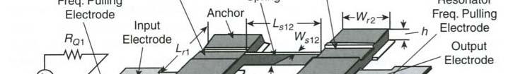
17 2-resonator HF-VHF micromechanical filter The coupled resonator filter may be classified as a 2-port: Two c-c c beams 0.1 μm over substrate Determined by thickness of sacrificial oxide Soft coupling spring polysi stripes under each resonator electrodes Vibrations normal to substrate DC voltage applied polysi at the edges function as tuning electrodes ( beam-softening ) 17


18 Resistors AC-signal on input electrode through R Q 1 R Q1 reduces overall Q and makes the pass band more flat Matched impedance at output, t R Q2 R s may be tailored to specific applications e.g. may be adjusted for interfacing to a following LNA 18
19 Mechanical signal processing This unit shows: Signal processing can be done in the mechanical domain Electrical input signal is converted to force By capacitive input transducer Mechanical displacements (vibrations) are induced in x- direction due to the varying force The resulting mechanical signal is then processed in the mechanical domain Reject if outside pass band Passed if inside pass band 19
20 Mechanical signal processing, contd. The mechanically processed signal manifests itself as movement of the output transducer The movement is converted to electrical energy Output current i0 = Vd * dc/dt micromechanical ca signal processor The electrical signal can be further processed by succeeding transceiver stages 20
21 BP-filter using 2 c-c beam resonators 21
22 22
23 Filter response Frequency separation depends on the stiffness of the coupling spring Soft spring ( compliant ) close frequencies = narrow pass band Increased number of coupled resonators in a linear chain gives Wider pass band Increased number of passband ripples the total number of oscillation modes are equal to the number of coupled resonators in the chain 23
24 24
25 Filter design Resonators used in micromechanical i filters are normally identical Same dimension and resonance frequency Filter centre frequency is f0 (if massless coupling spring ) Pass band determined by max distance between node tops Relative position of vibration tops is determined by k k sij Coupling spring stiffness Resonator properties (spring constant) at coupling points k r 25
26 Design, contd. At centre frequency f0 and bandwidth B, spring constants must fulfill k ij f k k ij k B 0 = normalized coupling coefficient taken from filter cook books k sij Ratio important, t NOT absolute values kr Theoretical design procedure A* (* can not be implemented in practice) f 0 k k Determine and Choose for required BW I real life this procedure is modified (procedure B ) r sij sij r 26
27 Design procedures c-c c beam filter A. Design resonators first This will give constraints for selecting the stiffness of the coupling beam but bandwidth B can not be chosen freely! or B. Design coupling beam spring constant first Determine the spring constant the resonator must have for a given BW this determines the coupling points! 27
28 Design procedure A. A1. Determine resonator geometry for a given frequency and a specific material (ρ) Calculate beam-length (Lr), thickness (h) and gap (d) using equations for f0 and terminating resistors (RQ) If filter is symmetric and Q_resonator >> Q_filter, a simplified model for the resistors may be used 28
29 For a specific resonator frequency, geometry is determined by: E h 1 k e f0 const 1 2 L r k m 1/ 2 h L : determined from f requirement W, r 0 r, W e : chosen as practical as possible Added requirement : R R Q k re 0 q Q 1 filter 2 e, Q Q res Q filter k re : given by resonator dimensions : is given q 1 Q 0 : from filter cook book filter : is given C VP e VP : only possible variation 2 x d V : has limitations P d : can be changed! (e, is centre position of beam) 29
30 Design-procedure A, contd. A2. Choose a realistic width of fthe coupling beam W s12 Length of coupling beam should be a quarter wavelength of the filter centre frequency Coupling springs are in general transmission lines The filter will not be very sensitive to dimensional variations of the coupling beam if a quarter wavelength Quarter wavelength requirement determines the length of the coupling beam L s12 30
31 Design procedure A, contd. Constraints on width, thickness and length determines the coupling spring constant k k s12 This limits the possibility to set the bandwidth independently (BW depends on the coupling spring constant) f k 0 s12 B k12 krc An alternative method for determining the filterbandwidth is needed see design procedure B 31
32 Design procedure B B1. Use coupling points on the resonator to determine filter bandwidth BW determined by the ratio ks 12 k is the value of k at the coupling point! k rc position dependent, especially of the speed at the position k rc can be selected by choosing a proper coupling point rc of resonator beam! The dynamic spring constant for a c-c beam is largest nearby the anchors k rc is larger for smaller speed of coupling point at resonance k rc k rc 32
33 Smaller speed Max. speed const 0 m eff KE 1 v 2 k m eff eff 2 Smaller speed eff. mass higher eff. spring stiffness higher 2 33
34 Positioning of coupling beam So: filter bandwidth can be found by choosing a value of fulfilling the equation k r k sij f k B 0 ij k k where is given by the quarter wavelength requirement Choice of coupling point of resonator beam influences on the bandwidth of the mechanical filter sij r 34
35 Position of coupling beam 35
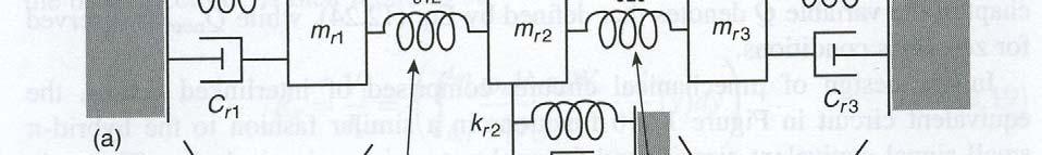
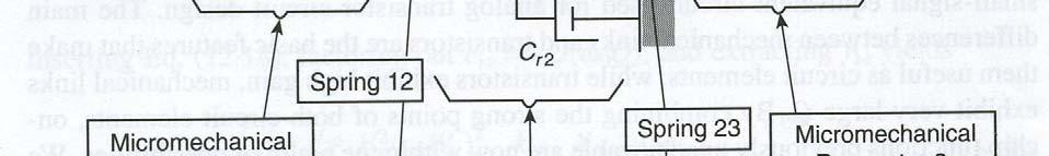
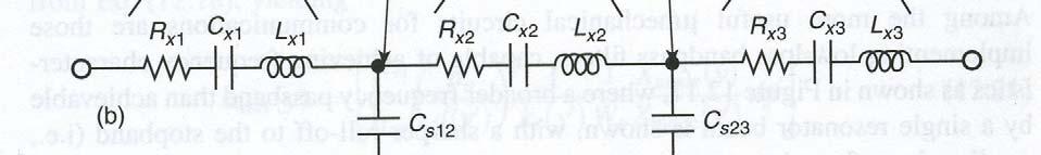
36 Design-procedure, contd. B2. Generate a complete equivalent circuit it for the whole filter structure and verify using a circuit simulator Equivalent circuit for 2-resonator filter Each resonator is modeled as shown before Coupling beam operates as an acoustic transmission line and is modeled as a T-network of energy storing elements Transformers are placed in-between resonator and coupling beam circuit to model velocity transformations that take place when coupling beam is connected at positions outside the resonator beam centre 36
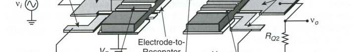
37 37


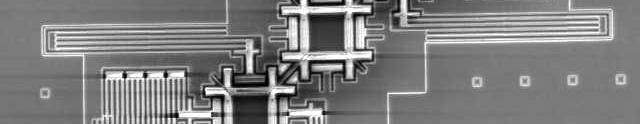
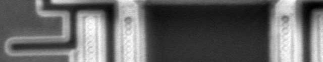
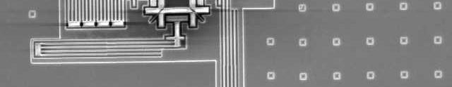
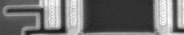
38 HF micromechanical filter Coupling position SEM of symmetric filter : 7.81 MHz l_c was adjusted to obtain the required Resonators consist of phosphor doped poly bandwidth Torsion rotation of coupling beam may also influence the mechanical coupling Effective value of l_c changes 38


39 HF micromechanical filter Measured and simulated frequency response BW = 18 khz, Insertion loss = 1.8 db, Q_filter = 435 Simulation and experimental results match well in pass band Large difference in the transition region to the stop band In a real filter poles that are not modeled, are introduced. They improve the filter shape factor, -due to the feedthrough capacitance C_p between input and output electrodes (parasitic element). For fully integrated t filters this capacitance can be controlled and the position of the poles can be chosen such that they contribute to a optimized filter performance 39


40 Comb structure Both series and parallel configurations can be used In figure 5.11.b the output currents are added 40
41 Comb-structure, contd. Resonators designed d for having different resonance frequencies Model taken from Varadan p : Model assumes a massless coupling beam. Possible to ignore the influence of the mass on the filter performance if the coupling beam length is a quarter wavelength of the centre frequency Formulas inaccurate for high frequencies and small dimensions Better method: Use advanced simulation tools f 2 f 1 f 1 Q 1 41
42 Filter implemented using comb structure 42
43 43
44 44
45 Micromechanical mixer filters A 2 c-c beam structure can be modified to be a mixer Suppose input signals on both on v_e (electrode) and v_b (beam) Fig Itoh, shows schematic for a symmetric micromechanical mixer-filter-structure 45
46 46
47 Mixer v RF electrode on Suppose v v LO b RF Force calculated: on beam, oscillator Suppose local t V v v x C v v v v x C v v F e e b b b e d cos ) 2 ( 2 1 ) ( Suppose : C V V F t V v v t V v v LO LO LO b RF RF RF e 2 1 cos cos Suppose : t t t t t t x C V V F RF LO RF LO d ] ) cos( ) cos( cos 2cos cos cos [where... t F t x C V V F LO RF LO RF d cos ) cos( F IFt d cos
48 Micromechanical mixer filters, contd. Summary of calculations l Start with a non-linear relationship between voltage and force: voltage/force characteristic (square) Linearization: Vp suppresses non-linearity Voltage signals v_rf and v_lo are mixed down to intermediate t frequency (force), ω_if = difference between frequencies! Transducer no. 1 can couple the signal into the following resonator If transducer no. 2 is designed as a micromechanical BP filter with centre frequency ω_ IF,, we will get an effective mixer-filter structure 48
 This is a component that t may replace present mixer + IFfilter (intermediate-filter) Lower contact-loss between")
49 Micromechanical mixer-filter, contd. Mixer structure is a functional-block in a RFsystem (future lecture) This is a component that t may replace present mixer + IFfilter (intermediate-filter) Lower contact-loss between parts and ideally zero DC power consumption A non-conducting coupling beam is used for isolating the IF- port (e.g. 2. beam) from LO (local oscillator) 49
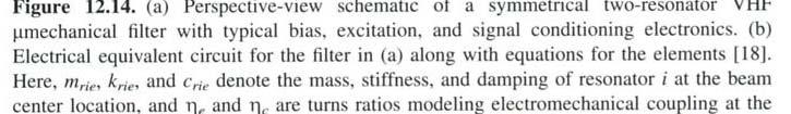
50 Mixer-filters using square-frame resonators Made using a post-cmos process Laterally moving structures Examples from research at the Nanoelectronics group 50
51 51 FFSFR architecture


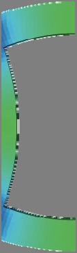


52 52 Free-free Square Frame Resonator
53 FFSFR w/self-assembly electrodes V LO A 4μm 18μm 1.8μm A V RF A A 53


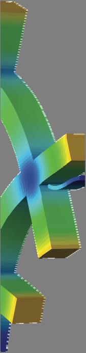
54 FFSFR filter design 45 support beams Can be used as a 45 coupling beam 54
55 55 4th order FFSFR mechanical filter


56 SEM pictures - 6th order FFSFR 56
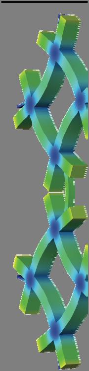


57 2 Mechanically coupled FFSFR MODE 1 MODE 2 Bandwidth = 71.6 khz fc = MHz 57
58 3 Mechanically coupled FFSFR MODE 1 MODE 2 MODE 3 Bandwidth = khz fc = MHz 58
59 59 Simulation results
INF 5490 RF MEMS. LN10: Micromechanical filters. Spring 2012, Oddvar Søråsen Department of Informatics, UoO
 INF 5490 RF MEMS LN10: Micromechanical filters Spring 2012, Oddvar Søråsen Department of Informatics, UoO 1 Today s lecture Properties of mechanical filters Visualization and working principle Modeling
INF 5490 RF MEMS. L12: Micromechanical filters. S2008, Oddvar Søråsen Department of Informatics, UoO
 INF 5490 RF MEMS L12: Micromechanical filters S2008, Oddvar Søråsen Department of Informatics, UoO 1 Today s lecture Properties of mechanical filters Visualization and working principle Design, modeling
Vibrating MEMS resonators
 Vibrating MEMS resonators Vibrating resonators can be scaled down to micrometer lengths Analogy with IC-technology Reduced dimensions give mass reduction and increased spring constant increased resonance
Frequency-Selective MEMS for Miniaturized Low-Power Communication Devices. Clark T.-C. Nguyen, Member, IEEE. (Invited Paper)
") 1486 IEEE TRANSACTIONS ON MICROWAVE THEORY AND TECHNIQUES, VOL. 47, NO. 8, AUGUST 1999 Frequency-Selective MEMS for Miniaturized Low-Power Communication Devices Clark T.-C. Nguyen, Member, IEEE (Invited
1486 IEEE TRANSACTIONS ON MICROWAVE THEORY AND TECHNIQUES, VOL. 47, NO. 8, AUGUST 1999 Frequency-Selective MEMS for Miniaturized Low-Power Communication Devices Clark T.-C. Nguyen, Member, IEEE (Invited
INF5490 RF MEMS. L7: RF MEMS switches, I. S2008, Oddvar Søråsen Department of Informatics, UoO
 INF5490 RF MEMS L7: RF MEMS switches, I S2008, Oddvar Søråsen Department of Informatics, UoO 1 Today s lecture Switches for RF and microwave Examples Performance requirements Technology Characteristics
Frequency-Selective MEMS for Miniaturized Communication Devices
 C. T.-C. Nguyen, Frequency-selective MEMS for miniaturized communication devices (invited), Proceedings, 1998 IEEE Aerospace Conference, vol. 1, Snowmass, Colorado, March 21-28, 1998, pp. 445-460. Frequency-Selective
INF 5490 RF MEMS. LN12: RF MEMS inductors. Spring 2011, Oddvar Søråsen Department of informatics, UoO
 INF 5490 RF MEMS LN12: RF MEMS inductors Spring 2011, Oddvar Søråsen Department of informatics, UoO 1 Today s lecture What is an inductor? MEMS -implemented inductors Modeling Different types of RF MEMS
PROBLEM SET #7. EEC247B / ME C218 INTRODUCTION TO MEMS DESIGN SPRING 2015 C. Nguyen. Issued: Monday, April 27, 2015
 Issued: Monday, April 27, 2015 PROBLEM SET #7 Due (at 9 a.m.): Friday, May 8, 2015, in the EE C247B HW box near 125 Cory. Gyroscopes are inertial sensors that measure rotation rate, which is an extremely
RF MEMS for Low-Power Communications
 RF MEMS for Low-Power Communications Clark T.-C. Nguyen Center for Wireless Integrated Microsystems Dept. of Electrical Engineering and Computer Science University of Michigan Ann Arbor, Michigan 48109-2122
Introduction to Microeletromechanical Systems (MEMS) Lecture 12 Topics. MEMS Overview
 Lecture 12 Topics. MEMS Overview") Introduction to Microeletromechanical Systems (MEMS) Lecture 2 Topics MEMS for Wireless Communication Components for Wireless Communication Mechanical/Electrical Systems Mechanical Resonators o Quality
Introduction to Microeletromechanical Systems (MEMS) Lecture 2 Topics MEMS for Wireless Communication Components for Wireless Communication Mechanical/Electrical Systems Mechanical Resonators o Quality
VIBRATING mechanical tank components, such as crystal. High-Order Medium Frequency Micromechanical Electronic Filters
 534 JOURNAL OF MICROELECTROMECHANICAL SYSTEMS, VOL. 8, NO. 4, DECEMBER 1999 High-Order Medium Frequency Micromechanical Electronic Filters Kun Wang, Student Member, IEEE, and Clark T.-C. Nguyen, Member,
Micromechanical Circuits for Wireless Communications
 Micromechanical Circuits for Wireless Communications Clark T.-C. Nguyen Center for Integrated Microsystems Dept. of Electrical Engineering and Computer Science University of Michigan Ann Arbor, Michigan
Third Order Intermodulation Distortion in Capacitive-Gap Transduced Micromechanical Filters
 Third Order Intermodulation Distortion in Capacitive-Gap Transduced Micromechanical Filters Jalal Naghsh Nilchi, Ruonan Liu, Scott Li, Mehmet Akgul, Tristan O. Rocheleau, and Clark T.-C. Nguyen Berkeley
DEVELOPMENT OF RF MEMS SYSTEMS
 DEVELOPMENT OF RF MEMS SYSTEMS Ivan Puchades, Ph.D. Research Assistant Professor Electrical and Microelectronic Engineering Kate Gleason College of Engineering Rochester Institute of Technology 82 Lomb
Chapter-2 LOW PASS FILTER DESIGN 2.1 INTRODUCTION
 Chapter-2 LOW PASS FILTER DESIGN 2.1 INTRODUCTION Low pass filters (LPF) are indispensable components in modern wireless communication systems especially in the microwave and satellite communication systems.
Micromechanical filters for miniaturized low-power communications
 C. T.-C. Nguyen, Micromechanical filters for miniaturized low-power communications (invited), to be published in Proceedings of SPIE: Smart Structures and Materials (Smart Electronics and MEMS), Newport
Chapter 2. The Fundamentals of Electronics: A Review
 Chapter 2 The Fundamentals of Electronics: A Review Topics Covered 2-1: Gain, Attenuation, and Decibels 2-2: Tuned Circuits 2-3: Filters 2-4: Fourier Theory 2-1: Gain, Attenuation, and Decibels Most circuits
Electrically coupled MEMS bandpass filters Part I: With coupling element
 Sensors and Actuators A 122 (2005) 307 316 Electrically coupled MEMS bandpass filters Part I: With coupling element Siavash Pourkamali, Farrokh Ayazi School of Electrical and Computer Engineering, Georgia
Design of Microstrip Coupled Line Bandpass Filter Using Synthesis Technique
 Design of Microstrip Coupled Line Bandpass Filter Using Synthesis Technique 1 P.Priyanka, 2 Dr.S.Maheswari, 1 PG Student, 2 Professor, Department of Electronics and Communication Engineering Panimalar
Design of Duplexers for Microwave Communication Systems Using Open-loop Square Microstrip Resonators
 International Journal of Electromagnetics and Applications 2016, 6(1): 7-12 DOI: 10.5923/j.ijea.20160601.02 Design of Duplexers for Microwave Communication Charles U. Ndujiuba 1,*, Samuel N. John 1, Taofeek
AN-1098 APPLICATION NOTE
 APPLICATION NOTE One Technology Way P.O. Box 9106 Norwood, MA 02062-9106, U.S.A. Tel: 781.329.4700 Fax: 781.461.3113 www.analog.com Methodology for Narrow-Band Interface Design Between High Performance
ISSCC 2006 / SESSION 33 / MOBILE TV / 33.4
 33.4 A Dual-Channel Direct-Conversion CMOS Receiver for Mobile Multimedia Broadcasting Vincenzo Peluso, Yang Xu, Peter Gazzerro, Yiwu Tang, Li Liu, Zhenbiao Li, Wei Xiong, Charles Persico Qualcomm, San
Switch-less Dual-frequency Reconfigurable CMOS Oscillator using One Single Piezoelectric AlN MEMS Resonator with Co-existing S0 and S1 Lamb-wave Modes
 From the SelectedWorks of Chengjie Zuo January, 11 Switch-less Dual-frequency Reconfigurable CMOS Oscillator using One Single Piezoelectric AlN MEMS Resonator with Co-existing S and S1 Lamb-wave Modes
Compact microstrip stepped-impedance lowpass filter with wide stopband using SICMRC
 LETTER IEICE Electronics Express, Vol.9, No.22, 1742 1747 Compact microstrip stepped-impedance lowpass filter with wide stopband using SICMRC Mohsen Hayati 1,2a) and Hamed Abbasi 1 1 Electrical and Electronics
Tapped Inductor Bandpass Filter Design. High Speed Signal Path Applications 7/21/2009 v1.6
 Tapped Inductor Bandpass Filter Design High Speed Signal Path Applications 7/1/009 v1.6 Tapped Inductor BP Filter 1 st order (6 db/oct) LOW frequency roll-off Shunt LT 4 th order (4 db/oct) HIGH frequency
High-κ dielectrically transduced MEMS thickness shear mode resonators and tunable channel-select RF filters
 Sensors and Actuators A 136 (2007) 527 539 High-κ dielectrically transduced MEMS thickness shear mode resonators and tunable channel-select RF filters Hengky Chandrahalim,1, Dana Weinstein 1, Lih Feng
REALIZATION OF TEMPERATURE COMPENSATED ALUMINUM NITRIDE MICRORESONATOR FILTERS WITH BANDWIDTHS BEYOND kt2 LIMIT
 University of New Mexico UNM Digital Repository Electrical and Computer Engineering ETDs Engineering ETDs 2-14-2014 REALIZATION OF TEMPERATURE COMPENSATED ALUMINUM NITRIDE MICRORESONATOR FILTERS WITH BANDWIDTHS
Introduction (cont )
") Active Filter 1 Introduction Filters are circuits that are capable of passing signals within a band of frequencies while rejecting or blocking signals of frequencies outside this band. This property of
Active Filter 1 Introduction Filters are circuits that are capable of passing signals within a band of frequencies while rejecting or blocking signals of frequencies outside this band. This property of
Dual-Frequency GNSS Front-End ASIC Design
 Dual-Frequency GNSS Front-End ASIC Design Ed. 01 15/06/11 In the last years Acorde has been involved in the design of ASIC prototypes for several EU-funded projects in the fields of FM-UWB communications
Commercially available GaAs MMIC processes allow the realisation of components that can be used to implement passive filters, these include:
 Sheet Code RFi0615 Technical Briefing Designing Digitally Tunable Microwave Filter MMICs Tunable filters are a vital component in broadband receivers and transmitters for defence and test/measurement applications.
Microelectromechanical Devices for Wireless Communications
 Microelectromechanical Devices for Wireless Communications Clark T.-C. Nguyen Center for Integrated Sensors and Circuits Department of Electrical Engineering and Computer Science University of Michigan
ISSCC 2006 / SESSION 16 / MEMS AND SENSORS / 16.1
 16.1 A 4.5mW Closed-Loop Σ Micro-Gravity CMOS-SOI Accelerometer Babak Vakili Amini, Reza Abdolvand, Farrokh Ayazi Georgia Institute of Technology, Atlanta, GA Recently, there has been an increasing demand
LF to 4 GHz High Linearity Y-Mixer ADL5350
 LF to GHz High Linearity Y-Mixer ADL535 FEATURES Broadband radio frequency (RF), intermediate frequency (IF), and local oscillator (LO) ports Conversion loss:. db Noise figure:.5 db High input IP3: 25
Power Reduction in RF
 Power Reduction in RF SoC Architecture using MEMS Eric Mercier 1 RF domain overview Technologies Piezoelectric materials Acoustic systems Ferroelectric materials Meta materials Magnetic materials RF MEMS
Design of Clamped-Clamped Beam Resonator in Thick-Film Epitaxial Polysilicon Technology
 Design of Clamped-Clamped Beam Resonator in Thick-Film Epitaxial Polysilicon Technology D. Galayko, A. Kaiser, B. Legrand, L. Buchaillot, D. Collard, C. Combi IEMN-ISEN UMR CNRS 8520 Lille, France ST MICROELECTRONICS
Microwave Circuits Design. Microwave Filters. high pass
 Used to control the frequency response at a certain point in a microwave system by providing transmission at frequencies within the passband of the filter and attenuation in the stopband of the filter.
Design of an Evanescent Mode Circular Waveguide 10 GHz Filter
 Design of an Evanescent Mode Circular Waveguide 10 GHz Filter NI AWR Design Environment, specifically Microwave Office circuit design software, was used to design the filters for a range of bandwidths
Design and Characterization of a RF Frequency-Hopping Filter
 Design and Characterization of a RF Frequency-Hopping Filter by Deepa Parvathy Ramachandran A thesis submitted in partial fulfillment of the requirements for the degree of Master of Science in Electrical
PHYS225 Lecture 15. Electronic Circuits
 PHYS225 Lecture 15 Electronic Circuits Last lecture Difference amplifier Differential input; single output Good CMRR, accurate gain, moderate input impedance Instrumentation amplifier Differential input;
IN-CHIP DEVICE-LAYER THERMAL ISOLATION OF MEMS RESONATOR FOR LOWER POWER BUDGET
 Proceedings of IMECE006 006 ASME International Mechanical Engineering Congress and Exposition November 5-10, 006, Chicago, Illinois, USA IMECE006-15176 IN-CHIP DEVICE-LAYER THERMAL ISOLATION OF MEMS RESONATOR
EXPERIMENT 1: Characteristics of Passive and Active Filters
 Kathmandu University Department of Electrical and Electronics Engineering ELECTRONICS AND ANALOG FILTER DESIGN LAB EXPERIMENT : Characteristics of Passive and Active Filters Objective: To understand the
Design Considerations for 5G mm-wave Receivers. Stefan Andersson, Lars Sundström, and Sven Mattisson
 Design Considerations for 5G mm-wave Receivers Stefan Andersson, Lars Sundström, and Sven Mattisson Outline Introduction to 5G @ mm-waves mm-wave on-chip frequency generation mm-wave analog front-end design
Research Article Wideband Microstrip 90 Hybrid Coupler Using High Pass Network
 Microwave Science and Technology, Article ID 854346, 6 pages http://dx.doi.org/1.1155/214/854346 Research Article Wideband Microstrip 9 Hybrid Coupler Using High Pass Network Leung Chiu Department of Electronic
Micromachining Technologies for Miniaturized Communication Devices
 Micromachining Technologies for Miniaturized Communication Devices Clark T.-C. Nguyen Center for Integrated Sensors and Circuits Department of Electrical Engineering and Computer Science University of
EKT 356 MICROWAVE COMMUNICATIONS CHAPTER 4: MICROWAVE FILTERS
 EKT 356 MICROWAVE COMMUNICATIONS CHAPTER 4: MICROWAVE FILTERS 1 INTRODUCTION What is a Microwave filter? linear 2-port network controls the frequency response at a certain point in a microwave system provides
CHAPTER 4 ULTRA WIDE BAND LOW NOISE AMPLIFIER DESIGN
 93 CHAPTER 4 ULTRA WIDE BAND LOW NOISE AMPLIFIER DESIGN 4.1 INTRODUCTION Ultra Wide Band (UWB) system is capable of transmitting data over a wide spectrum of frequency bands with low power and high data
Application Note SAW-Components
 Application Note SAW-Components Comparison between negative impedance oscillator (Colpitz oscillator) and feedback oscillator (Pierce structure) App.: Note #13 Author: Alexander Glas EPCOS AG Updated:
Design of a BAW Quadplexer Module Using NI AWR Software
 Application Note Design of a BAW Quadplexer Module Using NI AWR Software Overview With the development of the LTE-Advanced and orthogonal frequency division multiple access (OFDMA) techniques, multiple
Vibrating RF MEMS for Low Power Wireless Communications
 Vibrating RF MEMS for Low Power Wireless Communications Clark T.-C. Nguyen Center for Wireless Integrated Microsystems Dept. of Electrical Engineering and Computer Science University of Michigan Ann Arbor,
A Simple Bandpass Filter with Independently Tunable Center Frequency and Bandwidth
 Progress In Electromagnetics Research Letters, Vol. 69, 3 8, 27 A Simple Bandpass Filter with Independently Tunable Center Frequency and Bandwidth Bo Zhou *, Jing Pan Song, Feng Wei, and Xiao Wei Shi Abstract
Cascaded Channel-Select Filter Array Architecture Using High-K Transducers for Spectrum Analysis
 Cascaded Channel-Select Filter Array Architecture Using High-K Transducers for Spectrum Analysis Eugene Hwang, Tanay A. Gosavi, Sunil A. Bhave School of Electrical and Computer Engineering Cornell University
5.75 GHz Microstrip Bandpass Filter for ISM Band
 5.75 GHz Microstrip Bandpass Filter for ISM Band A. R. Othman, I. M. Ibrahim, M. F. M. Selamat 3, M. S. A. S. Samingan 4, A. A. A. Aziz 5, H. C. Halim 6 Fakulti Kejuruteraan Elektronik Dan Kejuruteraan
PARALLEL coupled-line filters are widely used in microwave
 2812 IEEE TRANSACTIONS ON MICROWAVE THEORY AND TECHNIQUES, VOL. 53, NO. 9, SEPTEMBER 2005 Improved Coupled-Microstrip Filter Design Using Effective Even-Mode and Odd-Mode Characteristic Impedances Hong-Ming
Receiver Architecture
 Receiver Architecture Receiver basics Channel selection why not at RF? BPF first or LNA first? Direct digitization of RF signal Receiver architectures Sub-sampling receiver noise problem Heterodyne receiver
AN-1364 APPLICATION NOTE
 APPLICATION NOTE One Technology Way P.O. Box 916 Norwood, MA 262-916, U.S.A. Tel: 781.329.47 Fax: 781.461.3113 www.analog.com Differential Filter Design for a Receive Chain in Communication Systems by
An Oscillator Scheme for Quartz Crystal Characterization.
 An Oscillator Scheme for Quartz Crystal Characterization. Wes Hayward, 15Nov07 The familiar quartz crystal is modeled with the circuit shown below containing a series inductor, capacitor, and equivalent
Low Distortion Mixer AD831
 a FEATURES Doubly-Balanced Mixer Low Distortion +2 dbm Third Order Intercept (IP3) + dbm 1 db Compression Point Low LO Drive Required: dbm Bandwidth MHz RF and LO Input Bandwidths 2 MHz Differential Current
PRODUCT APPLICATION NOTES
 Extending the HMC189MS8 Passive Frequency Doubler Operating Range with External Matching General Description The HMC189MS8 is a miniature passive frequency doubler in a plastic 8-lead MSOP package. The
Progress In Electromagnetics Research, Vol. 107, , 2010
 Progress In Electromagnetics Research, Vol. 107, 101 114, 2010 DESIGN OF A HIGH BAND ISOLATION DIPLEXER FOR GPS AND WLAN SYSTEM USING MODIFIED STEPPED-IMPEDANCE RESONATORS R.-Y. Yang Department of Materials
Narrowband Microstrip Filter Design With NI AWR Microwave Office
 Narrowband Microstrip Filter Design With NI AWR Microwave Office Daniel G. Swanson, Jr. DGS Associates, LLC Boulder, CO dan@dgsboulder.com www.dgsboulder.com Narrowband Microstrip Filters There are many
Lecture 20: Passive Mixers
 EECS 142 Lecture 20: Passive Mixers Prof. Ali M. Niknejad University of California, Berkeley Copyright c 2005 by Ali M. Niknejad A. M. Niknejad University of California, Berkeley EECS 142 Lecture 20 p.
Application Note 5525
 Using the Wafer Scale Packaged Detector in 2 to 6 GHz Applications Application Note 5525 Introduction The is a broadband directional coupler with integrated temperature compensated detector designed for
RF Integrated Circuits
 Introduction and Motivation RF Integrated Circuits The recent explosion in the radio frequency (RF) and wireless market has caught the semiconductor industry by surprise. The increasing demand for affordable
RF Circuit Synthesis for Physical Wireless Design
 RF Circuit Synthesis for Physical Wireless Design Overview Subjects Review Of Common Design Tasks Break Down And Dissect Design Task Review Non-Synthesis Methods Show A Better Way To Solve Complex Design
Lowpass Filters. Microwave Filter Design. Chp5. Lowpass Filters. Prof. Tzong-Lin Wu. Department of Electrical Engineering National Taiwan University
 Microwave Filter Design Chp5. Lowpass Filters Prof. Tzong-Lin Wu Department of Electrical Engineering National Taiwan University Lowpass Filters Design steps Select an appropriate lowpass filter prototype
VALLIAMMAI ENGINEERING COLLEGE
 VALLIAMMAI ENGINEERING COLLEGE SRM Nagar, Kattankulathur 603 203 DEPARTMENT OF ELECTRONICS AND COMMUNICATION ENGINEERING QUESTION BANK II SEMESTER/ M.E COMMUNICATION SYSTEMS CU 5201 MIC and RF System Design
Radio Receiver Architectures and Analysis
 Radio Receiver Architectures and Analysis Robert Wilson December 6, 01 Abstract This article discusses some common receiver architectures and analyzes some of the impairments that apply to each. 1 Contents
AlN Contour-Mode Resonators for Narrow-Band Filters above 3 GHz
 From the SelectedWorks of Chengjie Zuo April, 2009 AlN Contour-Mode Resonators for Narrow-Band Filters above 3 GHz Matteo Rinaldi, University of Pennsylvania Chiara Zuniga, University of Pennsylvania Chengjie
Low Distortion Mixer AD831
 Low Distortion Mixer AD831 FEATURES Doubly Balanced Mixer Low Distortion +24 dbm Third Order Intercept (IP3) +1 dbm 1 db Compression Point Low LO Drive Required: 1 dbm Bandwidth 5 MHz RF and LO Input Bandwidths
ALMA MEMO #360 Design of Sideband Separation SIS Mixer for 3 mm Band
 ALMA MEMO #360 Design of Sideband Separation SIS Mixer for 3 mm Band V. Vassilev and V. Belitsky Onsala Space Observatory, Chalmers University of Technology ABSTRACT As a part of Onsala development of
Design and Analysis of Parallel-Coupled Line Bandpass Filter
 Design and Analysis of Parallel-Coupled Line Bandpass Filter Talib Mahmood Ali Asst. Lecturer, Electrical Engineering Department, University of Mustansiriyah, Baghdad, Iraq Abstract A compact microwave
ELECTROSTATIC FREE-FREE BEAM MICROELECTROMECHANICAL RESONATOR. Tianming Zhang
 ELECTROSTATIC FREE-FREE BEAM MICROELECTROMECHANICAL RESONATOR by Tianming Zhang Submitted in partial fulfilment of the requirements for the degree of Master of Applied Science at Dalhousie University Halifax,
2.97-GHz CVD Diamond Ring Resonator With Q >40,000
 Proceedings, 2012 IEEE Int. Frequency Control Symposium, Baltimore, Maryland, May 22-24, 2012, to be published. 2.97-GHz CVD Diamond Ring Resonator With Q >40,000 Thura Lin Naing, Turker Beyazoglu, Lingqi
CHAPTER 2 THE DESIGN OF ACTIVE POLYPHASE FILTER
 CHAPTER 2 THE DESIGN OF ACTIVE POLYPHASE FILTER 2.1 INTRODUCTION The fast growth of wireless applications in recent years has driven intense efforts to design highly integrated, high-performance, low-cost
Integration of AlN Micromechanical Contour- Mode Technology Filters with Three-Finger Dual Beam AlN MEMS Switches
 University of Pennsylvania From the SelectedWorks of Nipun Sinha 29 Integration of AlN Micromechanical Contour- Mode Technology Filters with Three-Finger Dual Beam AlN MEMS Switches Nipun Sinha, University
Novel Design of Compact Low Pass Filter using Defected Ground Structure
 76 VOL. 4, NO. 5, SEPTEMBER 9 Novel Design of Compact Low Pass Filter using Defected Ground Structure A.K.Verma 1 and Ashwani Kumar 1 Microwave Research Laboratory, Deptt.of Electronic Science, University
Design of an Evanescent Mode Circular Waveguide 10 GHz Filter
 Application Note Design of an Evanescent Mode Circular Waveguide 10 GHz Filter Overview Ham radio operation at 10 GHz is far removed from global shortwave communication typically operating below 30 MHz.
Lecture 4. Maximum Transfer of Power. The Purpose of Matching. Lecture 4 RF Amplifier Design. Johan Wernehag Electrical and Information Technology
 Johan Wernehag, EIT Lecture 4 RF Amplifier Design Johan Wernehag Electrical and Information Technology Design of Matching Networks Various Purposes of Matching Voltage-, Current- and Power Matching Design
Body-Biased Complementary Logic Implemented Using AlN Piezoelectric MEMS Switches
 University of Pennsylvania From the SelectedWorks of Nipun Sinha 29 Body-Biased Complementary Logic Implemented Using AlN Piezoelectric MEMS Switches Nipun Sinha, University of Pennsylvania Timothy S.
Evaluation Board Analog Output Functions and Characteristics
 Evaluation Board Analog Output Functions and Characteristics Application Note July 2002 AN1023 Introduction The ISL5239 Evaluation Board includes the circuit provisions to convert the baseband digital
Chapter 2. Inductor Design for RFIC Applications
 Chapter 2 Inductor Design for RFIC Applications 2.1 Introduction A current carrying conductor generates magnetic field and a changing current generates changing magnetic field. According to Faraday s laws
MEMS Technologies and Devices for Single-Chip RF Front-Ends
 MEMS Technologies and Devices for Single-Chip RF Front-Ends Clark T.-C. Nguyen Dept. of Electrical Engineering & Computer Science University of Michigan Ann Arbor, Michigan 48105-2122 CCMT 06 April 25,
Hybrid Ultra-Compact 4th Order Band-Pass Filters Based On Piezoelectric AlN Contour- Mode MEMS Resonators
 From the Selectedorks of Chengjie Zuo Summer June 1, 2008 Hybrid Ultra-Compact 4th Order Band-Pass Filters Based On Piezoelectric AlN Contour- Mode MEMS Resonators Chengjie Zuo, University of Pennsylvania
Top View (Near-side) Side View Bottom View (Far-side) .89±.08. 4x.280. Orientation Marker Orientation Marker.
 Side View Bottom View (Far-side) .89±.08. 4x.280. Orientation Marker Orientation Marker.") Model B2F2AHF Ultra Low Profile 168 Balun Ω to 2Ω Balanced Description The B2F2AHF is a low profile sub-miniature balanced to unbalanced transformer designed for differential input locations on data conversion
Model B2F2AHF Ultra Low Profile 168 Balun Ω to 2Ω Balanced Description The B2F2AHF is a low profile sub-miniature balanced to unbalanced transformer designed for differential input locations on data conversion
CHAPTER 3 CMOS LOW NOISE AMPLIFIERS
 46 CHAPTER 3 CMOS LOW NOISE AMPLIFIERS 3.1 INTRODUCTION The Low Noise Amplifier (LNA) plays an important role in the receiver design. LNA serves as the first block in the RF receiver. It is a critical
System on a Chip. Prof. Dr. Michael Kraft
 System on a Chip Prof. Dr. Michael Kraft Lecture 4: Filters Filters General Theory Continuous Time Filters Background Filters are used to separate signals in the frequency domain, e.g. remove noise, tune
DESIGN OF COMPACT MICROSTRIP LOW-PASS FIL- TER WITH ULTRA-WIDE STOPBAND USING SIRS
 Progress In Electromagnetics Research Letters, Vol. 18, 179 186, 21 DESIGN OF COMPACT MICROSTRIP LOW-PASS FIL- TER WITH ULTRA-WIDE STOPBAND USING SIRS L. Wang, H. C. Yang, and Y. Li School of Physical
PART. MAX7421CUA 0 C to +70 C 8 µmax INPUT CLOCK
 19-181; Rev ; 11/ 5th-Order, Lowpass, General Description The MAX718 MAX75 5th-order, low-pass, switchedcapacitor filters (SCFs) operate from a single +5 (MAX718 MAX71) or +3 (MAX7 MAX75) supply. These
Technician License Course Chapter 3 Types of Radios and Radio Circuits. Module 7
 Technician License Course Chapter 3 Types of Radios and Radio Circuits Module 7 Radio Block Diagrams Radio Circuits can be shown as functional blocks connected together. Knowing the description of common
A NOVEL COUPLING METHOD TO DESIGN A MI- CROSTRIP BANDPASS FILER WITH A WIDE REJEC- TION BAND
 Progress In Electromagnetics Research C, Vol. 14, 45 52, 2010 A NOVEL COUPLING METHOD TO DESIGN A MI- CROSTRIP BANDPASS FILER WITH A WIDE REJEC- TION BAND R.-Y. Yang, J.-S. Lin, and H.-S. Li Department
1-13GHz Wideband LNA utilizing a Transformer as a Compact Inter-stage Network in 65nm CMOS
 -3GHz Wideband LNA utilizing a Transformer as a Compact Inter-stage Network in 65nm CMOS Hyohyun Nam and Jung-Dong Park a Division of Electronics and Electrical Engineering, Dongguk University, Seoul E-mail
Research Article Compact and Wideband Parallel-Strip 180 Hybrid Coupler with Arbitrary Power Division Ratios
 Microwave Science and Technology Volume 13, Article ID 56734, 1 pages http://dx.doi.org/1.1155/13/56734 Research Article Compact and Wideband Parallel-Strip 18 Hybrid Coupler with Arbitrary Power Division
A TUNABLE GHz BANDPASS FILTER BASED ON SINGLE MODE
 Progress In Electromagnetics Research, Vol. 135, 261 269, 2013 A TUNABLE 1.4 2.5 GHz BANDPASS FILTER BASED ON SINGLE MODE Yanyi Wang *, Feng Wei, He Xu, and Xiaowei Shi National Laboratory of Science and
THIN-FILM PIEZOELECTRIC-ON-SUBSTRATE RESONATORS AND NARROWBAND FILTERS
 THIN-FILM PIEZOELECTRIC-ON-SUBSTRATE RESONATORS AND NARROWBAND FILTERS A Thesis Presented to The Academic Faculty by Reza Abdolvand In Partial Fulfillment of the Requirements for the Degree of Doctor of
Session 3. CMOS RF IC Design Principles
 Session 3 CMOS RF IC Design Principles Session Delivered by: D. Varun 1 Session Topics Standards RF wireless communications Multi standard RF transceivers RF front end architectures Frequency down conversion
CHAPTER 4. Practical Design
 CHAPTER 4 Practical Design The results in Chapter 3 indicate that the 2-D CCS TL can be used to synthesize a wider range of characteristic impedance, flatten propagation characteristics, and place passive
SP 22.3: A 12mW Wide Dynamic Range CMOS Front-End for a Portable GPS Receiver
 SP 22.3: A 12mW Wide Dynamic Range CMOS Front-End for a Portable GPS Receiver Arvin R. Shahani, Derek K. Shaeffer, Thomas H. Lee Stanford University, Stanford, CA At submicron channel lengths, CMOS is
MEMS Reference Oscillators. EECS 242B Fall 2014 Prof. Ali M. Niknejad
 MEMS Reference Oscillators EECS 242B Fall 2014 Prof. Ali M. Niknejad Why replace XTAL Resonators? XTAL resonators have excellent performance in terms of quality factor (Q ~ 100,000), temperature stability
Waveguide-Mounted RF MEMS for Tunable W-band Analog Type Phase Shifter
 Waveguide-Mounted RF MEMS for Tunable W-band Analog Type Phase Shifter D. PSYCHOGIOU 1, J. HESSELBARTH 1, Y. LI 2, S. KÜHNE 2, C. HIEROLD 2 1 Laboratory for Electromagnetic Fields and Microwave Electronics
264 MHz HTS Lumped Element Bandpass Filter
 IEICE SAITO TRANS. et al: 264 ELECTRON., MHz HTS LUMPED VOL. E83-C, ELEMENT NO. 1 JANUARY BANDPASS 2 FILTER 15 PAPER Special Issue on Superconductive Devices and Systems 264 MHz HTS Lumped Element Bandpass