FP-II / Master Laboratory. Optical Pumping
|
|
|
- Kory Moore
- 5 years ago
- Views:
Transcription
1 .
2 Institut für Mathematik und Physik Albert-Ludwigs-Universität Freiburg im Breisgau Feb I
3 Contents 1 Introduction 1 2 Experimental Setup 1 3 Measurement Procedures Characterisation of the laser diode Spectroscopy of the hyperfine structure Double-resonance experiments Spin precession Relaxation time Dehmelt s method: Inversion of the magnetic field Franzen s method: Relaxation in the dark References 12 II
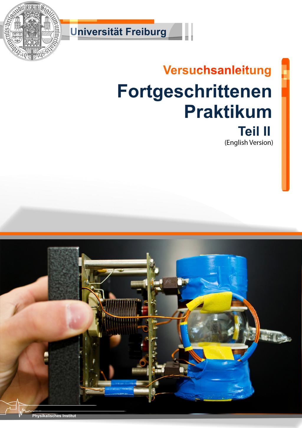
4 1 Introduction In 1949, Kastler introduced concepts of optical pumping based on the groundbreaking work of Hanle. First experiments on ground-state polarisation by optical pumping were performed by von Brossel, Kastler, and Winter and by Hawkins, and Dicke. In 1966, Kastler got awarded with the Nobelprize for his contributions to this work. For an extensive introduction we refer you to Sec. I of Ref. [Ha72] and common text books, e.g., Ref. [Co77]. In this advanced laboratory physics experiment, you study the process of optical pumping, i.e., the fundamental interaction between light and matter. You use circularly polarised light from a laser source to prepare a well defined ground-state level of a Rubidium sample. Further, you apply static and oscillating magnetic fields to manipulate the population distribution of these levels. Applying these common atomic physics techniques you determine, e.g., the nuclear magnetic moment of Rb. You apply the two distinct methods of Dehmelt [De57] and Franzen [Fr59] to determine the relaxation times within your setup. Details on all measurements and the experimental setup are described in Ref. [Ba97]. Please be prepared for the measurements and present a solid knowledge about the following topics: diode laser (working principle), atomic physics (fine and hyperfine structure, and Zeeman effect, relaxation processes), and light-matter interaction (light polarisation states, absorption and emission processes, selection rules, linewidth, line broadening effects, and optical pumping principle). 2 Experimental Setup We present an overview of the experimental setup arranged around a spherical glass cell filled with natural abundant Rubidium, with the two isotopes 85 Rb ( 72.8 %) and 87 Rb ( 27.2 %). The cell has an diameter of about 5 cm and is, additionally, filled with a Krypton buffer gas at a pressure of about 150 Pa. The buffer gas is used to reduce the mean free path length of Rb atoms in the cell and in this way it reduces Doppler broadening of absorption lines in Rb. To increase the partial pressure of Rb in the glass cell you may use a hairdryer prior to your measurements. You will observe an increase in your absorption signal. Be careful when handling the cell as it may brake easily. We use a diode laser (Hitachi HL 7801E) for the optical pumping and it s wavelength is adjusted by the temperature (coarse tuning) and the current (fine tuning) of the diode. Please obey appropriate laser safety measures at all times. When operating at a fixed temperature the diode frequency (wavelength) is fine tuned by 3.6(1) GHz ma 1 near 795 nm. The diode temperature is controlled and stabilised by a Peltier element and with the corresponding controller (Peltierregler) you can set it with a precision of about 0.1 C. The diode current is set with a dedicated controller. You can select the current (set or actual current values are shown on a display) and with the button Output you can switch between the output settings: on (current is applied to the diode) and off. For the experiments you may use the external input (with a corresponding switch on the backside) of the controller to modulate the diode current with a maximum bandwidth of about 500 khz (bandwidth switch set to High). You can apply a signal from an external source (function generator). The diode current controller limits the maximum current applied to the diode to prevent destruction; a flashing LED on the controller indicates that you select to high currents. Do NOT change the current limit. When the red LED on the controller lights up it indicates an error. You should turn the current as well as the modulation input to zero and push the reset button. Turn on the output again and increase the current again (up to values smaller than the current limit). When the error persists you should ask your assistant for advice, before proceeding. Note, that fine tuning of the wavelength can be limited by mode jumps at certain temperature and current settings. You may need to iteratively adjust temperature and current setting to find parameter settings that enable fine tuning across the entire D1 multiplet of Rb, cp. Fig. 1. In order to measure and, in turn, calibrate relative frequency detunings of the laser you may use the Fabry-Perot etalon. It has a free spectral range (FSR) of 9.92(3) GHz and can be put directly into the laser beam path. In addition, you find several neutral density filter to reduce the laser intensity and further optical elements (wave plates and linear polariser) to adjust and measure the laser polarisation. 1
5 Figure 1: Simplified level scheme for the Rb isotopes: 85 Rb und 87 Rb. Figure adapted from [Ba97]. To detect the the laser intensity you may use a photodiode (PD) that is equipped with an amplifier and the output signal of the amplifier can be monitored with an oscilloscope. The amplifier is optimised for 50-Ohm. You need to add a 50 Ohm terminator to your signal line going to the oscilloscope. For laser beam shaping (collimation and focusing) you may use dedicated lenses. Four different pairs of magnetic-field coils in Helmholz configuration can be used to apply homogenous magnetic fields to the Rb sample; they are labelled 1 to 4. Coils #1 to #3 are aligned collinear with the laser beam (along z direction), while coil #4 is aligned transversal to the laser beam (along x direction). The latter may be used for compensation of the vertical component of the Earth s and other stray magnetic fields. Specifications of the magnetic field coils are listed in Tab. 1. Dedicated constant-current power supplies may be used to adjust corresponding field strengths. Use 3.5 mm cables to connect the coils to the power supplies. Further, you may apply variable (longitudinal) magnetic fields via additional coils #5 in your experiments. Each #5 coil has n = 5 windings, is mounted directly onto the glass cell, and can be connected with a BNC cable. You may use a radio-frequency (RF) generator to apply RF radiation to the Rb sample via a RF emitter mounted directly onto the glass cell. To control the broadcasting power you can vary the corresponding control voltage U B ; maximum output power is set with U B = 30 V. A coarse and fine dial adjust the 2
6 ( Vs ) Am 2 ( Vs ) Am 2 B Coil # n d (m) calc. I measured B I (1) (1) (1) 10 4 Table 1: Calculated and measured B/I of the magnetic-field coils #1-#4 with n windings and inner diameter d. output frequency and you may use the oscilloscope or a counter to measure the set frequency. 3 Measurement Procedures 3.1 Characterisation of the laser diode Characterise the relative laser frequency variation for variable diode laser temperatures and drive currents using the etalon. Instructions: Turn on the temperature controller and the diode current controller of the diode laser. The laser system needs some time to thermalise (within the laboratory environment) before it s output wavelength (and power) is sufficiently stable for your measurements. Turn on/off the laser emission by switching the output of the diode controller. You may need to adjust the diode temperature around 34.6 C and diode current until the output wavelength is close to the Rb D1 line (fluorescence light may be seen with a mobile phone camera). You may use the PD amplifier with gain setting 40 db. When optimising the beam bath use the DCoutput for a signal proportional to the light power entering the PD. When data taking you may use the AC-output as this signal has a larger bandwidth. Attach the 9V battery to bias the PD for maximum bandwidth. Remove the glass cell from the beam path and put in the etalon. Note, make sure the etalon is adjusted such that the laser beam enters orthogonal to it s surface. Modulate the diode current with a sawtooth signal with constant offset current and constant temperature setting. Check the quality of your modulation signal on the oscilloscope and choose a range for your measurements where the voltage variation is most linear. Optimise the beam path by increasing the etalon transmission signal on the PD. Take calibration measurements of the laser frequency (wavelength) variation as a function of temperature and diode current. Vary only one parameter in a measurement sequence and avoid mode jumps during your sequences. However, you should record representative signals indicating mode jumps, in order to present and discuss this systematic effect in your final analysis. 3.2 Spectroscopy of the hyperfine structure Perform absorption spectroscopy of the 2 S 1/2 to 2 P 1/2 transition of 85 Rb and 87 Rb and determine the underlying hyperfine structure, cp. Fig. 1. In Table 2, we list literature values of relevant hyperfine constants. A schematic of the experimental setup is shown in Fig. 2. HFS const. A 85 Rb (I = 5/2) 87 Rb (I = 3/2) 2 S 1/ µev µev 2 P 1/ µev µev Table 2: Hyperfine constants A of the 2 S 1/2 and 2 P 1/2 levels of Rb [Co77]. 3
7 Figure 2: Schematic of the experimental setup for the absorption spectroscopy of 85 Rb und 87 Rb. Remove the central unit and insert the etalon to perform calibration measurements of the relative laser frequency variation. Figure adapted from [Ba97]. Instructions: 1. Put the glass cell (central unit) into the beam path (without the etalon). Modulate the laser frequency by applying a sawtooth signal to the diode current with a peak voltage of about 100 mv at fixed diode temperature of 34.6 C. Optimise diode laser settings to record the entire D1- absorption spectrum. Use variable frequencies and different slopes of the modulation signal to study systematic variations of the absorption line shapes. We recommend that you increase the absorption signal by increasing the partial pressure of Rb in the cell. 2. For each measurements sequence you need calibration measurements of the relative laser frequency tuning, in order to analyse your spectra. Use the etalon for these calibrations, while the central unit is removed. 3. Identify individual hyperfine transitions by applying appropriate selections rules and determine the hyperfine constants A of the 2 S 1/2 and 2 P 1/2 levels from your spectra. 3.3 Double-resonance experiments Measurement of the nuclear spin I of both Rb isotopes by optical pumping and RF radiation tuned to double-resonance. Further, the transversal and longitudinal component of the stray magnetic field are to be determined. Generation of circular polarised light Detection of the absorption signal during the resonant irradiation of laser light and RF radiation Compensation of the vertical component of the stray magnetic field 4
8 Measurement and compensation of the longitudinal component of stray magnetic fields Measurement of the nuclear spin I of 85 Rb and 87 Rb Figure 3 sketches the setup for the double-resonance experiments. The magnetic field generated by coil #1 causes a splitting of the magnetic sub-levels. The splitting is illustrated in Fig. 1 and, in the case, Figure 3: Setup for the measurement of the nuclear spin of both Rb isotopes via the doubleresonance method: The setup is extend with a quarter wave plate for the generation of circular polarised light. The radio-frequency emitter is mounted directly on the glass cell. It s frequency can be tuned via the potentiometers on the central unit, its amplitude is adjusted via the power supply. The frequency can be checked at the monitor output using a frequency counter or an oscilloscope. The constant magnetic field are applied via coil #1 and #4. The additional oscillating magnetic field is applied via coil #2. Figure adapted from [Ba97]. of low magnetic fields. Here, the level splitting is approximately equidistant and can be sufficiently described by the Zeeman effect. The energy splitting of neighbouring magnetic-sub states ( m F = 1) in Rb (in the ground state) is given by: E B = µ BB I + 1/2. (1) Here, I denotes the nuclear spin of each isotope, B is the external magnetic field strength, and µ B is the Bohr magneton. At room temperatures the ground state levels are (almost) equally populated. Due to the optical pumping, there is a significant deviation of the occupation numbers compared to the equilibrium state. Irradiation of resonant circular polarised light (e.g., σ + light) prepares the ground state F = max, m F = ±F. Ideally, all atoms are pumped into this stretched state. In this case, light is fully transmitted and the PD detects maximal intensity. The RF radiation redistributes population between the magnetic-sub levels with maximal rate when E B = hν RF, with the RF frequency ν RF [cp. Eq. (1)]. In turn, absorption of laser light increases again and the PD detects minimal intensity. 5
9 Instructions: 1. Laser is driven at fixed temperature and current; circular polarised light is produced with a quarter wave plate; the orientation of the wave plate is checked with the help of a linear polariser for coarse tuning. For fine tuning you optimise the double-resonance signal. 2. Choose the laser wavelength such that optical pumping occurs and use a sinusoidal modulation of the current through coil #2 with large amplitude to find the necessary magnetic-field range. In the measurements you may choose smaller amplitudes. The RF is applied with fixed ν RF 500 khz and U B 10 V. Optimise the laser diode current for maximal absorption; find two current settings (at fixed laser temperature), one for each isotope. 3. The laser is driven with the settings determined above. The current of coil #1 is chosen in a way that you get equidistant absorption peaks with twice the frequency of the modulation of the magnetic field 1. Note, that the oscilloscope records the applied voltage and not the current of coil #2; take the corresponding phase shift into account. 4. Coil #4 is used to compensate the vertical component of the stray magnetic fields: The current is tuned, such that the absorptions is maximal (check applied polarity). The corresponding magnetic field can be calculated from the characteristics of the coil (see Tab. 1) and the applied current. Keep the vertical compensation for the following measurements. 5. When changing the polarity of the current through coil #1, you need to adjust the current value, to get again equidistant absorption peaks. The difference in the current values between both configurations enables us to determine the longitudinal component of the stray magnetic field. 6. When the transversal component of the stray magnetic field is near compensated, you can calculate the nuclear spin of the Rubidium isotopes at double resonance and equidistant absorptions according to I = µ BB h ν RF 1 2, (2) taking the longitudinal component of the total magnetic field into account. 3.4 Spin precession Measurement of weak magnetic fields by observation of the spin precession. Figure 4 sketches the setup to determine the vertical component of the stray magnetic field by the observation of spin precession. The resonant, circular polarised laser beam polarises the Rb along the external magnetic field (sum of stray and applied magnetic fields). When turning off (on) the applied field fast enough (faster than the precession time in the stray magnetic field), the polarisation of the Rb ensemble can not follow the fast changing magnetic field and remains stationary. In absence of the field generated by the coils, the ensemble experiences a torsional moment due to the transversal component of the stray magnetic field and precesses with frequency: ω L = g F µ B h B stray,trans. (3) The polarisation vector follows this precession and the Rb changes with each period from a state of maximum transparency in z-direction into a state of maximum absorption., i.e., the intensity of the transmitted light is a function of time. We can determine the transversal component of the stray magnetic field by the measuring the frequency ν osz of the absorption signal: B Earth,trans = h g F µ B ν osz. (4) 1 If there is no absorption, you have to change the diode current, until double-resonance occurs. Optical pumping occurs only in a small region of diode current and laser temperature. 6
10 Figure 4: Setup for the spin precession measurements. The additional coil #5 generates the variable longitudinal magnetic field. The longitudinal components of the stray magnetic field is compensated with coil #1 and its transversal component is compensated with coil #4. Figure adapted from [Ba97]. Instructions: 1. Compensation of the longitudinal component of the stray magnetic field by applying a current to coil #1. It s current is known from the double-resonance experiment, while it s transversal component remains uncompensated. 2. The current of coil #5 is periodically switched on and off (choose a rectangular-puls sequence with DC-offset). This coil has a low inductivity and, so far, best results are produced with the instec function generator. Averaging the signal (with the oscilloscope) will increase the signal to noise ratio, but requires a stable trigger signal. 3. With a time resolution of 5 µs/div at the oscilloscope, one can observe the spin precession after the falling edge of the magnetic field. We show in Fig. 5 a typical trace of the spin-precession signal triggered by the magnetic-field inversion. 4. The transversal magnetic field can be calculated from the frequency of the spin precession. When tuning the current of coil #4 and rotating the experimental table, one may reduce the transversal component of the stray magnetic field. You need to record the spin precession for each parameter setting and compare the quantities of the calculated and measured magnetic fields. 3.5 Relaxation time Measurement of the relaxation time of the pumped ensembles with the method of Dehmelt (3.5.1) with inversion of the magnetic field and with the method of Franzen (3.5.2) via relaxation in the dark, when 7
11 Figure 5: Illustration of a spin-precession signal of a Rb isotope (black) and of a signal indicating the magnetic-field inversion (grey). Here, the transversal stray-magnetic fields are compensated. Further, the trigger position is shown and labelled. the optical pumping light is turned off. While the optical pumping polarises the Rb any relaxation mechanism acts against the pumping process and depolarises the atoms: When the pumping light is turned off, the polarisation decays. This decay is described by an exponential function with characteristic relaxation time T R. During the illumination of the ensemble with pumping light, relaxation and pumping process compete against each other and the relevant time constant τ (orientation time) is given by: 1 τ = (5) T P T R Here the pumping time is denoted by T P and is inverse proportional to the pump light intensity I light : T P 1 I light. (6) There are two relevant relaxation processes: Rb atoms colliding with the glass cell or with buffer gas. Further, we only consider the first: When assuming that the polarisation of Rb atoms is completely lost during a single collision with the glass cell, we can estimate the relaxation time from the diffusion rate 1/T D in the given spherical geometry of the glass cell [Co77]: 1 = D 0p 0 T D p ( ) 2 2π. (7) d In this equation, d is the diameter of the cell, p denotes the pressure in the cell, and D 0 is the diffusions coefficient of Rb in a buffer gas with constant pressure p 0 (literature values listed in Tab. 3) Dehmelt s method: Inversion of the magnetic field Time-resolved observation of the absorption signal of the pumped ensemble after flipping the direction of the applied magnetic field Determination of the orientation time τ for different light intensities Extract the relaxation time T R and compare it to calculated values Figure 6 sketches the relevant experimental setup. Optically pumped Rb is polarised along the magnetic 8
12 Buffer gas D 0 [cm 2 s 1 ] He 0,7 Ne 0,5 Ar 0,4 Kr 0,16 Xe 0,13 Table 3: Diffusions coefficients D 0 for Rb in buffer gas at constant pressure p 0 = kpa Figure 6: Experimental setup for determination of T R with the method of inverting magnetic-field introduced by Dehmelt. Figure adapted from [Ba97]. field by the polarised laser light. When at t = 0 the direction of the applied magnetic field is flipped abruptly, the Rb is pumped into the opposite stretched state within T P. For example, if most of the Rb is prepared in F = 2, m F = 2 prior to the flipping of the magnetic field, it gets subsequently pumped into F = 2, m F = 2 2. Due to the pumping process, the transmission of light through the cell increases exponentially with the orientation time τ, cp. Fig. 7. While τ is defined as the duration at which 1 1/e = 63.2 % of the maximal transmission is reached. From measurements taken with variable pump-light intensity, we can determine the relaxation time T R [De57]. Instructions: 1. Choose laser settings such that it addresses both Rb isotopes Coil #3 is used to generate a longitudinal oscillating magnetic field, while coil #4 is used to compensate the vertical component of stray magnetic fields. 2 This example is given for 87 Rb. 3 It maybe that the settings need to be (re-) adjusted during the measurement 9
13 Figure 7: Illustration of the transmission signal during a measurement of the orientation duration τ. Figure adapted from [Ba97]. 3. The orientation time τ is measured for variable pump-light intensity using different neutral-density filters. You should take calibration measurements of the transmission through the neutral-density filters. Further, we recommend that you increase the absorption signal by increasing the partial pressure of Rb in the cell. 4. Plot your results for 1/τ as a function of light intensity and determine T R Franzen s method: Relaxation in the dark Time-resolved observation of the absorption signal after switching off/on the pump light Determination of the absorption signal for different durations in the dark t Superposition of the absorption signals for different t and determination of the time of relaxation T R. Figure 8 illustrates the required experimental setup. When the pump light is interrupted by the chopper disk (driven at variable speed), the polarised Rb relaxes until the light is unblocked and it can re-pump the Rb. The relaxation time T R can be determined from the analysis of the time-resolved absorption signals taken at variable durations in the dark t (chopper speeds). Figure 9 shows the shape of the absorption signal as a function of sequence duration t. For t T R, the system is able to fully relax in the dark, i.e., a uniform distribution of the level population is restored, and the repumping starts from maximal absorption: I max I min. The initial transmitted intensity (absorption level) as function of t is described by: ( I ( t) = I min + (I max I min ) exp t ). (8) T R You can use this relation to determine the relaxation time T R [Ba97, NH, Co77]. Instructions: The laser is periodically blocked by the chopper disk driven at variable rotation speed, while the laser wavelength is adjusted for maximal absorption. We recommend that you increase the absorption signal by increasing the partial pressure of Rb in the cell. Record time-resolved absorption signals for different t Determination of T R from a model fit of Eq. 8 to your data. Compare this result with your result for T R from Dehmelt s method and discuss systematic differences of both methods. 10
14 Figure 8: Experimental setup for the measurement with Franzen s method for the determination of the time of relaxation. Figure adapted from [Ba97]. Figure 9: Illustration of the transmission signal expected during the measurements following a relaxation in the dark (Franzen s method). References [Ba97] Baur, C.: Optisches Pumpen mit Laserdioden, Staatsexamensarbeit, Universität Freiburg,
15 [Co77] Corney, A.: Atomic And Laser Spectroscopy, Oxford University Press, 1977 [NH] Nagel, M.; Haworth, F.E.: Advanced Laboratory Experiments on of Rubidium Atoms-Part II, Free Precission, American Journal of Physics, Vol. 34, 559 (1966) [Fr59] Franzen, W.: Spin Relaxation of Optically Aligned Rubidium Vapour, Phys.Rev.115, 850 (1959) [Ha72] Happer, W.:, Rev. mod. Phvs 44, 169 (1972) [De57] Dehmelt, H.G.: Slow Spin Relaxation of Optically Polarized Sodium Atoms, Phys. Rev. 105, 1487 (1957) [Ko96] Kohlrausch, F.: Praktische Physik, Teubner Verlag, 24. Auflage,
Optical Pumping Control Unit
 (Advanced) Experimental Physics V85.0112/G85.2075 Optical Pumping Control Unit Fall, 2012 10/16/2012 Introduction This document is gives an overview of the optical pumping control unit. Magnetic Fields
Laser Locking with Doppler-free Saturated Absorption Spectroscopy
 Laser Locking with Doppler-free Saturated Absorption Spectroscopy Paul L. Stubbs, Advisor: Irina Novikova W&M Quantum Optics Group May 12, 2010 Abstract The goal of this project was to lock the frequency
R. J. Jones Optical Sciences OPTI 511L Fall 2017
 R. J. Jones Optical Sciences OPTI 511L Fall 2017 Semiconductor Lasers (2 weeks) Semiconductor (diode) lasers are by far the most widely used lasers today. Their small size and properties of the light output
Multi-photon Absorption in Optical Pumping of Rubidium
 Multi-photon Absorption in Optical Pumping of Rubidium Xinyi Xu (ID PIN:A51481739) Department of Physics and Astronomy Michigan State University Abstract: In optical pumping of rubidium, a new kind of
Doppler-Free Spetroscopy of Rubidium
 Doppler-Free Spetroscopy of Rubidium Pranjal Vachaspati, Sabrina Pasterski MIT Department of Physics (Dated: April 17, 2013) We present a technique for spectroscopy of rubidium that eliminates doppler
DIODE LASER SPECTROSCOPY (160309)
") DIODE LASER SPECTROSCOPY (160309) Introduction The purpose of this laboratory exercise is to illustrate how we may investigate tiny energy splittings in an atomic system using laser spectroscopy. As an
DIODE LASER SPECTROSCOPY (160309) Introduction The purpose of this laboratory exercise is to illustrate how we may investigate tiny energy splittings in an atomic system using laser spectroscopy. As an
Zeeman Shifted Modulation Transfer Spectroscopy in Atomic Cesium
 Zeeman Shifted Modulation Transfer Spectroscopy in Atomic Cesium Modulation transfer spectroscopy (MTS) is a useful technique for locking a laser on one of the closed cesium D transitions. We have focused
Electron Spin Resonance v2.0
 Electron Spin Resonance v2.0 Background. This experiment measures the dimensionless g-factor (g s ) of an unpaired electron using the technique of Electron Spin Resonance, also known as Electron Paramagnetic
Quantum frequency standard Priority: Filing: Grant: Publication: Description
 C Quantum frequency standard Inventors: A.K.Dmitriev, M.G.Gurov, S.M.Kobtsev, A.V.Ivanenko. Priority: 2010-01-11 Filing: 2010-01-11 Grant: 2011-08-10 Publication: 2011-08-10 Description The present invention
Spectrometer using a tunable diode laser
 Spectrometer using a tunable diode laser Ricardo Vasquez Department of Physics, Purdue University, West Lafayette, IN April, 2000 In the following paper the construction of a simple spectrometer using
레이저의주파수안정화방법및그응용 박상언 ( 한국표준과학연구원, 길이시간센터 )
") 레이저의주파수안정화방법및그응용 박상언 ( 한국표준과학연구원, 길이시간센터 ) Contents Frequency references Frequency locking methods Basic principle of loop filter Example of lock box circuits Quantifying frequency stability Applications
레이저의주파수안정화방법및그응용 박상언 ( 한국표준과학연구원, 길이시간센터 ) Contents Frequency references Frequency locking methods Basic principle of loop filter Example of lock box circuits Quantifying frequency stability Applications
MASSACHUSETTS INSTITUTE OF TECHNOLOGY Department of Electrical Engineering and Computer Science
 Student Name Date MASSACHUSETTS INSTITUTE OF TECHNOLOGY Department of Electrical Engineering and Computer Science 6.161 Modern Optics Project Laboratory Laboratory Exercise No. 6 Fall 2010 Solid-State
Supplementary Figures
 1 Supplementary Figures a) f rep,1 Δf f rep,2 = f rep,1 +Δf RF Domain Optical Domain b) Aliasing region Supplementary Figure 1. Multi-heterdoyne beat note of two slightly shifted frequency combs. a Case
CHAPTER 5 FINE-TUNING OF AN ECDL WITH AN INTRACAVITY LIQUID CRYSTAL ELEMENT
 CHAPTER 5 FINE-TUNING OF AN ECDL WITH AN INTRACAVITY LIQUID CRYSTAL ELEMENT In this chapter, the experimental results for fine-tuning of the laser wavelength with an intracavity liquid crystal element
taccor Optional features Overview Turn-key GHz femtosecond laser
 taccor Turn-key GHz femtosecond laser Self-locking and maintaining Stable and robust True hands off turn-key system Wavelength tunable Integrated pump laser Overview The taccor is a unique turn-key femtosecond
Spectroscopy of Ruby Fluorescence Physics Advanced Physics Lab - Summer 2018 Don Heiman, Northeastern University, 1/12/2018
 1 Spectroscopy of Ruby Fluorescence Physics 3600 - Advanced Physics Lab - Summer 2018 Don Heiman, Northeastern University, 1/12/2018 I. INTRODUCTION The laser was invented in May 1960 by Theodor Maiman.
PHY3902 PHY3904. Nuclear magnetic resonance Laboratory Protocol
 PHY3902 PHY3904 Nuclear magnetic resonance Laboratory Protocol PHY3902 PHY3904 Nuclear magnetic resonance Laboratory Protocol GETTING STARTED You might be tempted now to put a sample in the probe and try
Intermediate and Advanced Labs PHY3802L/PHY4822L
 Intermediate and Advanced Labs PHY3802L/PHY4822L Torsional Oscillator and Torque Magnetometry Lab manual and related literature The torsional oscillator and torque magnetometry 1. Purpose Study the torsional
FPPO 1000 Fiber Laser Pumped Optical Parametric Oscillator: FPPO 1000 Product Manual
 Fiber Laser Pumped Optical Parametric Oscillator: FPPO 1000 Product Manual 2012 858 West Park Street, Eugene, OR 97401 www.mtinstruments.com Table of Contents Specifications and Overview... 1 General Layout...
Wavelength Control and Locking with Sub-MHz Precision
 Wavelength Control and Locking with Sub-MHz Precision A PZT actuator on one of the resonator mirrors enables the Verdi output wavelength to be rapidly tuned over a range of several GHz or tightly locked
Understanding the Magnetic Resonance Spectrum of Nitrogen Vacancy Centers in an Ensemble of Randomly-Oriented Nanodiamonds, Supporting Information
 Understanding the Magnetic Resonance Spectrum of Nitrogen Vacancy Centers in an Ensemble of Randomly-Oriented Nanodiamonds, Supporting Information Keunhong Jeong *1,2, Anna J. Parker *1,2, Ralph H. Page
Fabry Perot Resonator (CA-1140)
") Fabry Perot Resonator (CA-1140) The open frame Fabry Perot kit CA-1140 was designed for demonstration and investigation of characteristics like resonance, free spectral range and finesse of a resonator.
Fabry Perot Resonator (CA-1140) The open frame Fabry Perot kit CA-1140 was designed for demonstration and investigation of characteristics like resonance, free spectral range and finesse of a resonator.
Supplementary Materials for
 advances.sciencemag.org/cgi/content/full/2/4/e1501489/dc1 Supplementary Materials for A broadband chip-scale optical frequency synthesizer at 2.7 10 16 relative uncertainty Shu-Wei Huang, Jinghui Yang,
Fabry-Perot Cavity FP1-A INSTRUCTOR S MANUAL
 Fabry-Perot Cavity FP1-A INSTRUCTOR S MANUAL A PRODUCT OF TEACHSPIN, INC. TeachSpin, Inc. 2495 Main Street Suite 409 Buffalo, NY 14214-2153 Phone: (716) 885-4701 Fax: (716) 836-1077 WWW.TeachSpin.com TeachSpin
EXP 9 ESR (Electron Spin Resonance)
") EXP 9 ESR (Electron Spin Resonance) Introduction ESR in Theory The basic setup for electron spin resonance is shown in Fig 1. A test sample is placed in a uniform magnetic field. The sample is also wrapped
EXP 9 ESR (Electron Spin Resonance) Introduction ESR in Theory The basic setup for electron spin resonance is shown in Fig 1. A test sample is placed in a uniform magnetic field. The sample is also wrapped
Swept Wavelength Testing:
 Application Note 13 Swept Wavelength Testing: Characterizing the Tuning Linearity of Tunable Laser Sources In a swept-wavelength measurement system, the wavelength of a tunable laser source (TLS) is swept
Direct frequency comb saturation spectroscopy with an ultradense tooth spacing of 100 Hz D. A. Long, 1,* A. J. Fleisher, 1 and J. T.
 Direct frequency comb saturation spectroscopy with an ultradense tooth spacing of 100 Hz D. A. Long, 1,* A. J. Fleisher, 1 and J. T. Hodges 1 1 Material Measurement Laboratory, National Institute of Standards
Instructions for the Experiment
 Instructions for the Experiment Excitonic States in Atomically Thin Semiconductors 1. Introduction Alongside with electrical measurements, optical measurements are an indispensable tool for the study of
A Penning Trap for Precision Spectroscopy of Highly Charged Ions at HITRAP. Jörg Krämer University of Mainz
 A Penning Trap for Precision Spectroscopy of Highly Charged Ions at HITRAP University of Mainz Experimental Goal Precise measurement of the hyperfine splitting in highly charged ions (HCI) as a test of
Introduction to the operating principles of the HyperFine spectrometer
 Introduction to the operating principles of the HyperFine spectrometer LightMachinery Inc., 80 Colonnade Road North, Ottawa ON Canada A spectrometer is an optical instrument designed to split light into
Pound-Drever-Hall Locking of a Chip External Cavity Laser to a High-Finesse Cavity Using Vescent Photonics Lasers & Locking Electronics
 of a Chip External Cavity Laser to a High-Finesse Cavity Using Vescent Photonics Lasers & Locking Electronics 1. Introduction A Pound-Drever-Hall (PDH) lock 1 of a laser was performed as a precursor to
EE119 Introduction to Optical Engineering Spring 2002 Final Exam. Name:
 EE119 Introduction to Optical Engineering Spring 2002 Final Exam Name: SID: CLOSED BOOK. FOUR 8 1/2 X 11 SHEETS OF NOTES, AND SCIENTIFIC POCKET CALCULATOR PERMITTED. TIME ALLOTTED: 180 MINUTES Fundamental
3 General Principles of Operation of the S7500 Laser
 Application Note AN-2095 Controlling the S7500 CW Tunable Laser 1 Introduction This document explains the general principles of operation of Finisar s S7500 tunable laser. It provides a high-level description
Exp. #2-6 : Measurement of the Characteristics of,, and Circuits by Using an Oscilloscope
 PAGE 1/14 Exp. #2-6 : Measurement of the Characteristics of,, and Circuits by Using an Oscilloscope Student ID Major Name Team No. Experiment Lecturer Student's Mentioned Items Experiment Class Date Submission
PCS-150 / PCI-200 High Speed Boxcar Modules
 Becker & Hickl GmbH Kolonnenstr. 29 10829 Berlin Tel. 030 / 787 56 32 Fax. 030 / 787 57 34 email: info@becker-hickl.de http://www.becker-hickl.de PCSAPP.DOC PCS-150 / PCI-200 High Speed Boxcar Modules
ECE 185 ELECTRO-OPTIC MODULATION OF LIGHT
 ECE 185 ELECTRO-OPTIC MODULATION OF LIGHT I. Objective: To study the Pockels electro-optic (E-O) effect, and the property of light propagation in anisotropic medium, especially polarization-rotation effects.
Week IX: INTERFEROMETER EXPERIMENTS
 Week IX: INTERFEROMETER EXPERIMENTS Notes on Adjusting the Michelson Interference Caution: Do not touch the mirrors or beam splitters they are front surface and difficult to clean without damaging them.
B. Cavity-Enhanced Absorption Spectroscopy (CEAS)
") B. Cavity-Enhanced Absorption Spectroscopy (CEAS) CEAS is also known as ICOS (integrated cavity output spectroscopy). Developed in 1998 (Engeln et al.; O Keefe et al.) In cavity ringdown spectroscopy,
B. Cavity-Enhanced Absorption Spectroscopy (CEAS) CEAS is also known as ICOS (integrated cavity output spectroscopy). Developed in 1998 (Engeln et al.; O Keefe et al.) In cavity ringdown spectroscopy,
A novel tunable diode laser using volume holographic gratings
 A novel tunable diode laser using volume holographic gratings Christophe Moser *, Lawrence Ho and Frank Havermeyer Ondax, Inc. 85 E. Duarte Road, Monrovia, CA 9116, USA ABSTRACT We have developed a self-aligned
FIBER OPTICS. Prof. R.K. Shevgaonkar. Department of Electrical Engineering. Indian Institute of Technology, Bombay. Lecture: 18.
 FIBER OPTICS Prof. R.K. Shevgaonkar Department of Electrical Engineering Indian Institute of Technology, Bombay Lecture: 18 Optical Sources- Introduction to LASER Diodes Fiber Optics, Prof. R.K. Shevgaonkar,
Evaluation of Scientific Solutions Liquid Crystal Fabry-Perot Etalon
 Evaluation of Scientific Solutions Liquid Crystal Fabry-Perot Etalon Testing of the etalon was done using a frequency stabilized He-Ne laser. The beam from the laser was passed through a spatial filter
Optical Amplifiers (Chapter 6)
") Optical Amplifiers (Chapter 6) General optical amplifier theory Semiconductor Optical Amplifier (SOA) Raman Amplifiers Erbium-doped Fiber Amplifiers (EDFA) Read Chapter 6, pp. 226-266 Loss & dispersion
Optical Amplifiers (Chapter 6) General optical amplifier theory Semiconductor Optical Amplifier (SOA) Raman Amplifiers Erbium-doped Fiber Amplifiers (EDFA) Read Chapter 6, pp. 226-266 Loss & dispersion
The electric field for the wave sketched in Fig. 3-1 can be written as
 ELECTROMAGNETIC WAVES Light consists of an electric field and a magnetic field that oscillate at very high rates, of the order of 10 14 Hz. These fields travel in wavelike fashion at very high speeds.
Nd:YSO resonator array Transmission spectrum (a. u.) Supplementary Figure 1. An array of nano-beam resonators fabricated in Nd:YSO.
 Supplementary Figure 1. An array of nano-beam resonators fabricated in Nd:YSO.") a Nd:YSO resonator array µm Transmission spectrum (a. u.) b 4 F3/2-4I9/2 25 2 5 5 875 88 λ(nm) 885 Supplementary Figure. An array of nano-beam resonators fabricated in Nd:YSO. (a) Scanning electron microscope
a Nd:YSO resonator array µm Transmission spectrum (a. u.) b 4 F3/2-4I9/2 25 2 5 5 875 88 λ(nm) 885 Supplementary Figure. An array of nano-beam resonators fabricated in Nd:YSO. (a) Scanning electron microscope
A Narrow-Band Tunable Diode Laser System with Grating Feedback
 A Narrow-Band Tunable Diode Laser System with Grating Feedback S.P. Spirydovich Draft Abstract The description of diode laser was presented. The tuning laser system was built and aligned. The free run
Simple System for Active Frequency Stabilization of a Diode Laser in an External Cavity
 Laser Physics, Vol. 15, No. 11, 25, pp. 1 5. Original Text Copyright 25 by Astro, Ltd. English Translation Copyright 25 by MAIK Nauka /Interperiodica (Russia). RUBRRRIKA RUBRIKA Simple System for Active
Lecture 21. Wind Lidar (3) Direct Detection Doppler Lidar
 Direct Detection Doppler Lidar") Lecture 21. Wind Lidar (3) Direct Detection Doppler Lidar Overview of Direct Detection Doppler Lidar (DDL) Resonance fluorescence DDL Fringe imaging DDL Scanning FPI DDL FPI edge-filter DDL Absorption
Lecture 21. Wind Lidar (3) Direct Detection Doppler Lidar Overview of Direct Detection Doppler Lidar (DDL) Resonance fluorescence DDL Fringe imaging DDL Scanning FPI DDL FPI edge-filter DDL Absorption
Solar Cell Parameters and Equivalent Circuit
 9 Solar Cell Parameters and Equivalent Circuit 9.1 External solar cell parameters The main parameters that are used to characterise the performance of solar cells are the peak power P max, the short-circuit
First and second order systems. Part 1: First order systems: RC low pass filter and Thermopile. Goals: Department of Physics
 slide 1 Part 1: First order systems: RC low pass filter and Thermopile Goals: Understand the behavior and how to characterize first order measurement systems Learn how to operate: function generator, oscilloscope,
High-frequency tuning of high-powered DFB MOPA system with diffraction limited power up to 1.5W
 High-frequency tuning of high-powered DFB MOPA system with diffraction limited power up to 1.5W Joachim Sacher, Richard Knispel, Sandra Stry Sacher Lasertechnik GmbH, Hannah Arendt Str. 3-7, D-3537 Marburg,
Polarization Experiments Using Jones Calculus
 Polarization Experiments Using Jones Calculus Reference http://chaos.swarthmore.edu/courses/physics50_2008/p50_optics/04_polariz_matrices.pdf Theory In Jones calculus, the polarization state of light is
NORTHWESTERN UNIVERSITY MULTI-SPECTRAL RAMAN GAIN IN DUAL-ISOTOPE RUBIDIUM VAPOR A THESIS SUBMITTED TO THE GRADUATE SCHOOL
 NORTHWESTERN UNIVERSITY MULTI-SPECTRAL RAMAN GAIN IN DUAL-ISOTOPE RUBIDIUM VAPOR A THESIS SUBMITTED TO THE GRADUATE SCHOOL IN PARTIAL FULFILLMENT OF THE REQUIREMENTS for the degree MASTER OF SCIENCE Field
10. Phase Cycling and Pulsed Field Gradients Introduction to Phase Cycling - Quadrature images
 10. Phase Cycling and Pulsed Field Gradients 10.1 Introduction to Phase Cycling - Quadrature images The selection of coherence transfer pathways (CTP) by phase cycling or PFGs is the tool that allows the
NON-AMPLIFIED HIGH SPEED PHOTODETECTOR USER S GUIDE
 NON-AMPLIFIED HIGH SPEED PHOTODETECTOR USER S GUIDE Thank you for purchasing your Non-amplified High Speed Photodetector. This user s guide will help answer any questions you may have regarding the safe
atom physics seminar ultra short laser pulses
 atom physics seminar ultra short laser pulses creation and application ultra short laser pulses overview what? - why? - how? creation and optimisation typical experimental setup properties of existing
UTA EE5380 PhD Diagnosis Exam (Fall 2011) Principles of Photonics and Optical Engineering
 Principles of Photonics and Optical Engineering") EE 5380 Fall 2011 PhD Diagnosis Exam ID: UTA EE5380 PhD Diagnosis Exam (Fall 2011) Principles of Photonics and Optical Engineering Instructions: Verify that your exam contains 7 pages (including the cover
EE 5380 Fall 2011 PhD Diagnosis Exam ID: UTA EE5380 PhD Diagnosis Exam (Fall 2011) Principles of Photonics and Optical Engineering Instructions: Verify that your exam contains 7 pages (including the cover
MAGNETIC RESONANCE IMAGING
 CSEE 4620 Homework 3 Fall 2018 MAGNETIC RESONANCE IMAGING 1. THE PRIMARY MAGNET Magnetic resonance imaging requires a very strong static magnetic field to align the nuclei. Modern MRI scanners require
Be aware that there is no universal notation for the various quantities.
 Fourier Optics v2.4 Ray tracing is limited in its ability to describe optics because it ignores the wave properties of light. Diffraction is needed to explain image spatial resolution and contrast and
R. J. Jones College of Optical Sciences OPTI 511L Fall 2017
 R. J. Jones College of Optical Sciences OPTI 511L Fall 2017 Active Modelocking of a Helium-Neon Laser The generation of short optical pulses is important for a wide variety of applications, from time-resolved
Development of high-sensitivity magnetometer for EDM experiment with 129 Xe spin oscillator
 Development of high-sensitivity magnetometer for EDM experiment with 129 Xe spin oscillator A. Yoshimi RIKEN Nishina Center ( ~ 2011.9) Okayama University ( 2011.10 ~ ) T. Nanao 1, T. Inoue 1, M. Chikamori
Experiment One: Generating Frequency Modulation (FM) Using Voltage Controlled Oscillator (VCO)
 Using Voltage Controlled Oscillator (VCO)") Experiment One: Generating Frequency Modulation (FM) Using Voltage Controlled Oscillator (VCO) Modified from original TIMS Manual experiment by Mr. Faisel Tubbal. Objectives 1) Learn about VCO and how
Experiment One: Generating Frequency Modulation (FM) Using Voltage Controlled Oscillator (VCO) Modified from original TIMS Manual experiment by Mr. Faisel Tubbal. Objectives 1) Learn about VCO and how
EXPERIMENTAL STUDY OF THE LASER DIODE PUMPED RUBIDIUM MASER
 arxiv:physics/0508227v1 [physics.ins-det] 31 Aug 2005 EXPERIMENTAL STUDY OF THE LASER DIODE PUMPED RUBIDIUM MASER Alain Michaud, Pierre Tremblay and Michel Têtu Centre d optique, photonique et laser (COPL),
PMT tests at UMD. Vlasios Vasileiou Version st May 2006
 PMT tests at UMD Vlasios Vasileiou Version 1.0 1st May 2006 Abstract This memo describes the tests performed on three Milagro PMTs in UMD. Initially, pulse-height distributions of the PMT signals were
Lecture 6 Fiber Optical Communication Lecture 6, Slide 1
 Lecture 6 Optical transmitters Photon processes in light matter interaction Lasers Lasing conditions The rate equations CW operation Modulation response Noise Light emitting diodes (LED) Power Modulation
Fabry-Perot Interferometer
 Experimental Optics Contact: Maximilian Heck (maximilian.heck@uni-jena.de) Ria Krämer (ria.kraemer@uni-jena.de) Last edition: Ria Krämer, March 2017 Fabry-Perot Interferometer Contents 1 Overview 3 2 Safety
Development of a Prototype Atomic Clock Based on Coherent Population Trapping
 Development of a Prototype Atomic Clock Based on Coherent Population Trapping A thesis submitted in partial fulfillment of the requirement for the degree of Bachelor of Science Physics from the College
Communication using Synchronization of Chaos in Semiconductor Lasers with optoelectronic feedback
 Communication using Synchronization of Chaos in Semiconductor Lasers with optoelectronic feedback S. Tang, L. Illing, J. M. Liu, H. D. I. barbanel and M. B. Kennel Department of Electrical Engineering,
Laser frequency stabilization and large detuning by Doppler-free dichroic lock technique: Application to atom cooling
 PRAMANA c Indian Academy of Sciences Vol. 65, No. 3 journal of September 2005 physics pp. 403 411 Laser frequency stabilization and large detuning by Doppler-free dichroic lock technique: Application to
A Conceptual Tour of Pulsed NMR*
 A Conceptual Tour of Pulsed NMR* Many nuclei, but not all, possess both a magnetic moment, µ, and an angular momentum, L. Such particles are said to have spin. When the angular momentum and magnetic moment
DETECTING THE RATIO OF I AC
 T E C H N O L O G Y F O R P O L A R I Z A T I O N M E A S U R E M E N T DETECTING THE RATIO OF I AC MEASUREMENT OF THE RAGE INTENSITY OF A MODULATED LIGHT BEAM In any experiment using photoelastic modulators
Kit for building your own THz Time-Domain Spectrometer
 Kit for building your own THz Time-Domain Spectrometer 16/06/2016 1 Table of contents 0. Parts for the THz Kit... 3 1. Delay line... 4 2. Pulse generator and lock-in detector... 5 3. THz antennas... 6
Ph 3455 The Franck-Hertz Experiment
 Ph 3455 The Franck-Hertz Experiment Required background reading Tipler, Llewellyn, section 4-5 Prelab Questions 1. In this experiment, we will be using neon rather than mercury as described in the textbook.
Development of a new Q-meter module
 A. Berlin,, W. Meyer, G. Reicherz Experimentalphysik I, Ruhr-Universität Bochum E-mail: jonas.herick@rub.de In the research field of polarized target physics the Q-meter is a well established technique
R.B.V.R.R. WOMEN S COLLEGE (AUTONOMOUS) Narayanaguda, Hyderabad.
 Narayanaguda, Hyderabad.") R.B.V.R.R. WOMEN S COLLEGE (AUTONOMOUS) Narayanaguda, Hyderabad. DEPARTMENT OF PHYSICS QUESTION BANK FOR SEMESTER III PAPER III OPTICS UNIT I: 1. MATRIX METHODS IN PARAXIAL OPTICS 2. ABERATIONS UNIT II
R.B.V.R.R. WOMEN S COLLEGE (AUTONOMOUS) Narayanaguda, Hyderabad. DEPARTMENT OF PHYSICS QUESTION BANK FOR SEMESTER III PAPER III OPTICS UNIT I: 1. MATRIX METHODS IN PARAXIAL OPTICS 2. ABERATIONS UNIT II
Experimental Physics. Experiment C & D: Pulsed Laser & Dye Laser. Course: FY12. Project: The Pulsed Laser. Done by: Wael Al-Assadi & Irvin Mangwiza
 Experiment C & D: Course: FY1 The Pulsed Laser Done by: Wael Al-Assadi Mangwiza 8/1/ Wael Al Assadi Mangwiza Experiment C & D : Introduction: Course: FY1 Rev. 35. Page: of 16 1// In this experiment we
Your first NMR measurement
 Your first NMR measurement Introduction Select 10mM water in D2O as NMR sample. The NMR spectrum of such sample consists of only two signals: the water signal and the peak of the reference (TSP). Follow
Midterm #1 Prep. Revision: 2018/01/20. Professor M. Csele, Niagara College
 Midterm #1 Prep Revision: 2018/01/20 Professor M. Csele, Niagara College Portions of this presentation are Copyright John Wiley & Sons, 2004 Review Material Safety Finding MPE for a laser Calculating OD
The Discussion of this exercise covers the following points:
 Exercise 3-2 Frequency-Modulated CW Radar EXERCISE OBJECTIVE When you have completed this exercise, you will be familiar with FM ranging using frequency-modulated continuous-wave (FM-CW) radar. DISCUSSION
UNIVERSITY OF CALIFORNIA College of Engineering Department of Electrical Engineering and Computer Sciences
 UNIVERSITY OF CALIFORNIA College of Engineering Department of Electrical Engineering and Computer Sciences EECS 145L: Electronic Transducer Laboratory FINAL EXAMINATION Fall 2013 You have three hours to
Background (~EE369B)
") Background (~EE369B) Magnetic Resonance Imaging D. Nishimura Overview of NMR Hardware Image formation and k-space Excitation k-space Signals and contrast Signal-to-Noise Ratio (SNR) Pulse Sequences 13
Background (~EE369B) Magnetic Resonance Imaging D. Nishimura Overview of NMR Hardware Image formation and k-space Excitation k-space Signals and contrast Signal-to-Noise Ratio (SNR) Pulse Sequences 13
BLACKBODY RADIATION PHYSICS 359E
 BLACKBODY RADIATION PHYSICS 359E INTRODUCTION In this laboratory, you will make measurements intended to illustrate the Stefan-Boltzmann Law for the total radiated power per unit area I tot (in W m 2 )
Technical Report M-TR91
 Technical Report M-TR91 CESIUM OPTICALLY PUMPED MAGNETOMETERS Basic Theory of Operation Kenneth Smith - Geometrics, Inc Introduction: The following description of the theory of operation of the Cesium
Laser stabilization and frequency modulation for trapped-ion experiments
 Laser stabilization and frequency modulation for trapped-ion experiments Michael Matter Supervisor: Florian Leupold Semester project at Trapped Ion Quantum Information group July 16, 2014 Abstract A laser
Detecting the Ratio of I ac. /I ave. photoelastic modulators
 Measurement of the Average Intensity of a Modulated Light Beam In any experiment using (PEMs it is necessary to compare the time average intensity of the light at the detector with the amplitude of a single
Synchronization in Chaotic Vertical-Cavity Surface-Emitting Semiconductor Lasers
 Synchronization in Chaotic Vertical-Cavity Surface-Emitting Semiconductor Lasers Natsuki Fujiwara and Junji Ohtsubo Faculty of Engineering, Shizuoka University, 3-5-1 Johoku, Hamamatsu, 432-8561 Japan
Ph 77 ADVANCED PHYSICS LABORATORY ATOMIC AND OPTICAL PHYSICS
 Ph 77 ADVANCED PHYSICS LABORATORY ATOMIC AND OPTICAL PHYSICS Diode Laser Characteristics I. BACKGROUND Beginning in the mid 1960 s, before the development of semiconductor diode lasers, physicists mostly
MICROFABRICATED ATOMIC CLOCKS AT NIST
 MICROFABRICATED ATOMIC CLOCKS AT NIST S. Knappe *, P. D. D. Schwindt, V. Gerginov, V. Shah, L. Hollberg, J. Kitching Time and Frequency Division, NIST, Boulder, CO, USA L. Liew and J. Moreland Electromagnetics
Magnetometer Based on a Pair of Symmetric Transitions in the 87 Rb Hyperfine Structure
 ISSN 1063-7842, Technical Physics, 2006, Vol. 51, No. 7, pp. 919923. Pleiades Publishing, Inc., 2006. Original Russian Text E.B. Aleksandrov, A.K. Vershovskiœ, A.S. Pazgalev, 2006, published in Zhurnal
Imaging Systems Laboratory II. Laboratory 8: The Michelson Interferometer / Diffraction April 30 & May 02, 2002
 1051-232 Imaging Systems Laboratory II Laboratory 8: The Michelson Interferometer / Diffraction April 30 & May 02, 2002 Abstract. In the last lab, you saw that coherent light from two different locations
Experiment 1: Fraunhofer Diffraction of Light by a Single Slit
 Experiment 1: Fraunhofer Diffraction of Light by a Single Slit Purpose 1. To understand the theory of Fraunhofer diffraction of light at a single slit and at a circular aperture; 2. To learn how to measure
Introduction Fundamentals of laser Types of lasers Semiconductor lasers
 ECE 5368 Introduction Fundamentals of laser Types of lasers Semiconductor lasers Introduction Fundamentals of laser Types of lasers Semiconductor lasers How many types of lasers? Many many depending on
Characteristics of absorption and dispersion for rubidium D 2 lines with the modulation transfer spectrum
 Characteristics of absorption and dispersion for rubidium D 2 lines with the modulation transfer spectrum Jing Zhang, Dong Wei, Changde Xie, and Kunchi Peng The State Key Laboratory of Quantum Optics and
THE CHIP-SCALE ATOMIC CLOCK COHERENT POPULATION TRAPPING VS. CONVENTIONAL INTERROGATION
 THE CHIP-SCALE ATOMIC CLOCK COHERENT POPULATION TRAPPING VS. CONVENTIONAL INTERROGATION R. Lutwak, D. Emmons, W. Riley, and R. M. Garvey Symmetricom Technology Realization Center 34 Tozer Rd., Beverly,
PULSED NUCLEAR MAGNETIC RESONANCE. Advanced Laboratory, Physics 407 University of Wisconsin Madison, Wisconsin 53706
 (revised, 2/12/07) PULSED NUCLEAR MAGNETIC RESONANCE Advanced Laboratory, Physics 407 University of Wisconsin Madison, Wisconsin 53706 Abstract A pulsed nuclear magnetic resonance technique (spin-echo)
I = I 0 cos 2 θ (1.1)
") Chapter 1 Faraday Rotation Experiment objectives: Observe the Faraday Effect, the rotation of a light wave s polarization vector in a material with a magnetic field directed along the wave s direction.
Chapter 1 Faraday Rotation Experiment objectives: Observe the Faraday Effect, the rotation of a light wave s polarization vector in a material with a magnetic field directed along the wave s direction.
JEDI. Status of the commissioning of the waveguide RF Wien Filter
 COSY Beam Time Request For Lab. use Exp. No.: Session No. E 005.4 7 Collaboration: JEDI Status of the commissioning of the waveguide RF Wien Filter Spokespersons for the beam time: Ralf Gebel (Jülich)
The 34th International Physics Olympiad
 The 34th International Physics Olympiad Taipei, Taiwan Experimental Competition Wednesday, August 6, 2003 Time Available : 5 hours Please Read This First: 1. Use only the pen provided. 2. Use only the
COMPONENTS OF OPTICAL INSTRUMENTS. Chapter 7 UV, Visible and IR Instruments
 COMPONENTS OF OPTICAL INSTRUMENTS Chapter 7 UV, Visible and IR Instruments 1 Topics A. GENERAL DESIGNS B. SOURCES C. WAVELENGTH SELECTORS D. SAMPLE CONTAINERS E. RADIATION TRANSDUCERS F. SIGNAL PROCESSORS
COMPONENTS OF OPTICAL INSTRUMENTS. Topics
 COMPONENTS OF OPTICAL INSTRUMENTS Chapter 7 UV, Visible and IR Instruments Topics A. GENERAL DESIGNS B. SOURCES C. WAVELENGTH SELECTORS D. SAMPLE CONTAINERS E. RADIATION TRANSDUCERS F. SIGNAL PROCESSORS
Physics 476LW. Advanced Physics Laboratory - Microwave Optics
 Physics 476LW Advanced Physics Laboratory Microwave Radiation Introduction Setup The purpose of this lab is to better understand the various ways that interference of EM radiation manifests itself. However,