Customer Programming Software RG-1000e (CPS RG-1000e) User Guide. March 2018 R2.2.1
|
|
|
- Theresa Benson
- 5 years ago
- Views:
Transcription
1 Customer Programming Software RG-1000e (CPS RG-1000e) User Guide March 2018 R2.2.1
2 Table of Contents Table of Contents Foreword 3 Revision history 4 Introduction 5 1. RG-1000e Customer Programming Software (RG-1000e CPS) Software installation Connecting the RG-1000e to PC USB port CPS interface and main features CPS control panels Operation with configuration files Gateway panel Network section Radio 1&2 section Other Statistics section Monitor section Info section Radio settings MOTOTRBO settings non-mototrbo settings SmartPTT Radioserver settings Interaction with Mototrbo remote control stations in direct communication mode or with the use of single repeater (IP Site Connect network) Interaction with Mototrbo remote control stations in the Capacity Plus Legacy mode Interaction with Mototrbo remote control stations in the NAI Capacity Plus and NAI Linked Capacity Plus hybrid modes Interaction with non-mototrbo remote control stations (remote I\O control staition), for SmartPTT 9.3 and later Interaction with non-mototrbo remote control stations (using SmartPTT Call Emulation), for SmartPTT 9.2 and earlier Radio 1(2) port configuration samples 79
3 Table of Contents 4.1 Mototrbo, Radio 1(2) port settings APX\XTL, Radio 1(2) port setting, SmartPTT 9.3 or later APX\XTL, Radio 1(2) port settings, SmartPTT 9.2 or earlier MTM, Radio 1(2) port settings, SmartPTT 9.3 or later MTM, Radio 1(2) port settings, SmartPTT 9.2 or earlier SLR5500\XPR8300\XPR8400\XIRR8200, Radio 1(2) port settings, SmartPTT 9.3 or later SLR5500\XPR8300\XPR8400\XIRR8200, Radio 1(2) port settings, SmartPTT 9.2 or earlier 106 Appendix I RG-1000e driver installation 110
4 Foreword Foreword Disclaimer The information in this document is carefully examined, and is believed to be entirely reliable. However, no responsibility is assumed for inaccuracies. Furthermore, Elcomplus LLC reserves the right to make changes to any products herein to improve readability, function, or design. Elcomplus LLC does not assume any liability arising out of the applications or use of any product; nor does it cover any license under its patent rights nor the rights of others. Trademarks MOTOROLA SOLUTIONS, the Stylized M logo, MOTOTRBO are registered in the US Patent & Trademark Office. SmartPTT and RG-1000e are the property of Elcomplus LLC. All other product or service names are the property of their respective owners. 3
5 Revision history 4 Revision history This table describes the changes to the RG-1000e Customer Programming Software (RG-1000e CPS) user guide. Date Version Remarks May, 2017 CPS RG-1000e, R1.0 Initial release. July, 2017 CPS RG-1000e, R1.1 Updated GUI. October, 2017 CPS RG-1000e, R2.0 Updated GUI. New features are added. March, 2018 CPS RG-1000e, R2.2.1 Updated GUI. New features are added.
6 Introduction Introduction This guide describes the following features: how to install RG-1000e CPS, how to connect the RG-1000e GATEWAY to the computer's USB port, RG-1000e CPS interface and main features, MOTOTRBO radio parameters to work with a RG-1000e GATEWAY, SmartPTT Radioserver settings to work with a RG-1000e GATEWAY. 5
7 1. RG-1000e Customer Programming Software (RG-1000e CPS) 6 1. RG-1000e Customer Programming Software (RG-1000e CPS) RG-1000e CPS is intended for the specialist engineers who perform the RG-1000e GATEWAY configuration for remote management of the control radio station. When reading the RG-1000e GATEWAY configuration, RG-1000e CPS defines the gateway type automatically. RG-1000e CPS enables you to perform the following basic features: To gain access to the RG-1000e GATEWAY's configuration (download, read, write) and its modification. To update and recover the RG-1000e GATEWAY's processor program. To control the remote radio stations over the IP network. RG-1000e CPS is designed for operation in Windows XP, Windows 7, Windows 8/8.1, Windows 10. Note: RG-1000e CPS R2.2 can be used only for the RG-1000e GATEWAYs with firmware version R2.2.
8 1. RG-1000e Customer Programming Software (RG-1000e CPS) Software installation To install RG-1000e CPS, copy the Program folder from the unpacked distribution kit to your local disk and run the RG-1000e-XVXX.exe file. When copying the folder with the program, the program does not change the settings of the computer's operation system, except for the installation of the gateway driver for the USB port.
9 1. RG-1000e Customer Programming Software (RG-1000e CPS) Connecting the RG-1000e to PC USB port Before connecting the gateway make sure that the computer and gateway have a common ground or one of them is disconnected from the ground. If the RG-1000e GATEWAY and computer are connected to different grounding mats, damage to the USB ports may occur. When you connect the RG-1000e GATEWAY to a USB port for the first time, the computer's operation system will define the connection of the new device. Now you should install the new device driver. You can install the device driver in two ways (depends on Microsoft Windows OS): installing the setup driver files from the Driver folder, which is located in program home directory, or performing Update Driver Software via PC Device Manager. Having installed the driver, you are able to modify the RG-1000e GATEWAY configuration via the computer's USB port. When installing the USB driver in Windows 7/8/8.1/10 operating systems, you must have the computer's administrator rights. USB driver step by step installation procedure is provided in Appendix I.
10 1. RG-1000e Customer Programming Software (RG-1000e CPS) CPS interface and main features CPS control panels RG-1000e CPS has the following panels: The RG-1000e (Gateway) panel for operation with the RG-1000e GATEWAY configuration. The Report panel for program messages output. The File panel allows you to create, open and save the configuration files by clicking the Create, and Save or Save as, Open buttons correspondingly. You can also perform these actions via the File menu in the main menu of the program. The Tasks panel allows you to read and write the gateway configuration, by clicking the Read, Write buttons correspondingly. It also allows you to update the RG-1000e GATEWAY firmware, by clicking the Download firmware button (available in the Service mode only). You can also perform these actions via the Tasks menu in the main menu of the program or via the Tasks menu on the RG-1000e (Gateway) panel. To open the required panel, click Panels in the main menu of the program or right click in the area of the main menu and click the corresponding panel name. When downloading the RG-1000e GATEWAY configuration, the corresponding panel is opened automatically. To hide the panel, click its Cross button or click Panels or right click in the area of the main menu and click the required panel name.
11 1. RG-1000e Customer Programming Software (RG-1000e CPS) Operation with configuration files RG-1000e CPS enables you to work with a gateway configuration file in MCD format which contains the settings defining the RG-1000e GATEWAY operation via the RG-1000e (Gateway) panel. You can perform the following actions with the configuration files: create configuration file with the default settings, open configuration file, save configuration file, read configuration from the RG-1000e GATEWAY, and write configuration to the RG-1000e GATEWAY. To create a configuration file: 1. Click File > Create, or click Create in the File panel, or press Ctrl+N together. At that, the Save As window will open. 2. In case of gateway configuration file creation, click Yes in the window that opened. To open the configuration file: 1. Click File > Open, or click Open in the File panel, or press Ctrl+O together. At that, the Open window will open. 2. Select the required file and click Open. To save the configuration file: 1. Click File > Save, or click Save in the File panel, or press Ctrl+S together. At that, the Save As window will open. 2. Specify the file name in the corresponding field and click Save. You can also save the configuration file by clicking File > Save as, or clicking Save as in the File panel. To read the configuration from the RG-1000e GATEWAY, click Tasks > Read, or click Read in the Tasks panel. To write the configuration to the RG-1000e GATEWAY, click Tasks > Write, or click Write in the Tasks panel. Attention! Do not forget to reboot RG-1000e every time when the device is programmed with new settings: turn-off power for 7-10 sec and then turn-on (using Power button on RG-1000e front panel). Otherwise new settings will not be applied properly.

12 1. RG-1000e Customer Programming Software (RG-1000e CPS) Gateway panel The RG-1000e panel has the tree structure, which is created when creating the RG-1000e GATEWAY configuration file or reading the configuration from the RG-1000e GATEWAY. This tree structure combines the sections of gateway devices with various RG-1000e GATEWAY configuration operations. The RG-1000e panel helps to perform the following RG-1000e GATEWAY configuration operation: reading / writing configuration files and updating the RG-1000e GATEWAY firmware, modifying the settings, and getting statistic reports on the operation of gateway modules. To perform these operations, double-click the corresponding section in the panel tree: the Tasks section contains the operations listed in the Tasks panel description, the Network section, the Radio1&2 section, the Other section, the Statistics section, the Monitor section, the Info section. 11
13 1. RG-1000e Customer Programming Software (RG-1000e CPS) Network section The Network section contains the following gateway network parameters: eight IP channels, IP channel connection to the RG-1000e GATEWAY interfaces in the Mux subsection, and Ethernet port operation mode in the Driver subsection. 12

14 1. RG-1000e Customer Programming Software (RG-1000e CPS) 13 IP channel The IP channel window contains the network parameters of the corresponding IP channel. Note: When the RG-1000e GATEWAY uses several IP channels, the TCP and UDP port number values must not coincide. To open the IP Channel window, double-click the required IP Channel on the RG-1000e panel. The RG-1000e GATEWAYs have the following parameters: Mode/connection protocol, has the following values o Server mode, the mode is for operation with SmartPTT Radioserver. o TCP / RTP, the protocol is for operation with SmartPTT Radioserver. o Client mode, the mode is not used with SmartPTT Radioserver. o M-270/LCP, the protocol is not used with SmartPTT Radioserver. Getaway settings: o IP address, Subnet mask, Gateway: The network parameters. o XCMP protocol port, : UDP / TCP control command ports in accordance with the connection protocol. o RTP thread ports:
15 1. RG-1000e Customer Programming Software (RG-1000e CPS) 14 - Audio: The port of audio signal transmission from radio station to radioserver and backwards over the RTP streams. This port is used for operation with the TCP / RTP connection protocol. - ARS: The transmission port of data on registration of MOTOTRBO subscribers in the network. This port is used for operation with the TCP / RTP connection protocol. - TMS: The transmission port of text messages between the MOTOTRBO subscribers and readioserver. This port is used for operation with the TCP / RTP connection protocol. - Location: The transmission port of requests and messages about the location of MOTOTRBO subscribers (GPS). This port is used for operation with the TCP / RTP connection protocol. - Telemetry: The transmission port of requests and messages about the state of MOTOTRBO radio stations telemetry contacts (GPS). This port is used for operation with the TCP / RTP connection protocol. Note: the same port, for instance port 30010, may be used for XCMP, Audio, ARS, TMS, Location and Telemetry services within one selected IP channel. Attention! the same port or ports can not be shared between two or more IP channels. For each IP channel unique port or ports must be assigned. Remote getaway settings. It is not used with SmartPTT Radioserver operations. - IP address, the address of remote RG-1000e GETAWAY - XCMP port protocol, the port of remote remote RG-1000e GETAWAY. These settings are used when Radio Interface Mode is defined as Repeater. See chapter Radio section / Settings. See an additional document how to configure RG-1000e GATEWAYs to use Radio ports in Repeater mode.
16 1. RG-1000e Customer Programming Software (RG-1000e CPS) 15 Mux The Mux window serves for the IP channel distribution between the RG-1000e GATEWAY interfaces. The IP channels, not connected to any interface, are considered to be disabled and are not used by the RG-1000e GATEWAY. The IP channels that are not used by the RG-1000e GATEWAY must be disabled. To open the Mux window, double-click Mux on the RG-1000e panel. In the given example of the Mux window you can see that: Radio 1 interface is connected to IP channel 1. Radio 2 interface is connected to IP channel 2. You may assign several IP Channels for Radio 1 and Radio 2. For instance, two SmartPTT radioservers may communicate with Radio 1 via IP Channel 1 and IP Channel 3. For this case you should check boxes IP Channel 1 and IP Channel 3 for Radio 1 in the Mux window.

17 1. RG-1000e Customer Programming Software (RG-1000e CPS) 16 Driver The Driver window serves for the management of the following LAN RG-1000e GATEWAY operation modes: MDI/MDIX: The type of the connecting Ethernet cable, straight-through or crossed cable. Auto-Negotiation: Auto-negotiation of data transmission speed and mode. Fixed values of data transmission speed and mode. To open the Driver window, double-click Driver on the RG-1000e panel. When the Ethernet interface operates, side emission from the local network cable can penetrate into the radio station receiver antenna. On some frequencies it can lead to radio station receiving of interference from the RG1000e GATEWAY Ethernet interface. To reduce side emissions, the RG-1000e GATEWAY enables the user to control the Ethernet interface transmitter power. Power reduction decreases the emission level from the Ethernet cable. But it also can lead to the error increase in the Ethernet packets reception depending on the connected network equipment. You must check experimentally the compatibility and operational reliability of network equipment in partial operation mode. You can set the transmitter power for operation with 5 meter cable only in exceptional cases, and you must control the processes of reception and transmission of the Ethernet packets.
18 1. RG-1000e Customer Programming Software (RG-1000e CPS) Radio 1&2 section The Radio section contains the interface parameters for the radio station connection to the RG-1000e GATEWAY. The parameter control is performed via the following subsections: Radio 1: It serves for operation mode control of digital lines and analog inputs/outputs of the RG-1000e GATEWAY RADIO 1 port. Radio 2: It serves for operation mode control of digital lines and analog inputs/outputs of the RG-1000e GATEWAY RADIO 2 port Both the Radio 1 and Radio 2 subsections have the Settings, Audio RX, Audio encoder RX, Audio TX, Audio TxH and Audio encoder TX settings panels, which are described below.
19 1. RG-1000e Customer Programming Software (RG-1000e CPS) 18 Settings The Settings window defines operation modes of the RG-1000e GATEWAY interface lines depending on the type of connecting control panel or radio station model. RG-1000e GATEWAY general settings include the following components: To open the Settings window, double-click Settings on the RG-1000e panel in the Radio section. RG-1000e may operate in several modes. It allows to use RG-1000e as the part of SmartPTT dispatching system and as the independent device (without integration with SmartPTT). Available Radio 1(2) Interface modes: o Disabled: The RG-1000e GATEWAY does not use the interface. o Motorola DM: The RG-1000e GATEWAY lines are set to operate with MOTOTRBO mobile radios o Radio I\O: The RG-1000e GATEWAY lines are set to operate with non-mototrbo mobile radios using GPIO lines for connection with radios. o Bridge:This mode allows for several RG-1000e GATEWAYs communicate directly to each other and create simplest distributed radio networks. The RG-1000e GATEWAY lines are set to operate with various donor radios using GPIO lines for connection with radios. o Transit audio:this mode allows for several RG-1000e GATEWAYs communicate directly to each other and create simplest distributed networks for audio streaming.
20 1. RG-1000e Customer Programming Software (RG-1000e CPS) Note: Motorola GM mode is not supported. This User Guide describes how to configure Radio 1(2) interface for operation in Motorola DM and Radio I\O modes. 19
 socket, pin 25.")
21 1. RG-1000e Customer Programming Software (RG-1000e CPS) 20 Motorola DM mode Interface mode:set Mototrbo DM, select DM4000 for High Tier Mototrbo donor radio or DM2600 for Middle Tier Mototrbo donor radio. Getting power from connected devices: This option allows to get power for the RG-1000e via Radio 1 (or Radio 2) socket, pin 25. It is recommended turn-on this box for Mototrbo DM mode Attention! For detailed information about available power options and proper hardware installation you must read "RG-1000e Gateway User Guide" chapter 4. On\Off control to external devices: This option allows to change Radio 1 (or Radio 2) socket pin 13 status. If IP connection between SmartPTT radioserver and the RG-1000e gateway is active - pin 13 status is High (12VDC). If no IP connection between SmartPTT radioserver and the RG-1000e gateway - pin 13 status is Low (0VDC) It allows to use pin 13 for On-Off control purposes. Attention! Do not turn-on simultaneously both boxes Getting power form connected devices and On\Off control to external devices. Once IP link between SmartPTT radioserver and the RG-1000e is down there are no ways to turn-on the connected radio again. Sync IP channels: This mode enables to synchronize command transmission when operating with several radioservers. The commands are transmitted serially, after receiving the command reception confirmation from all remote radio stations. If the confirmation is not received from at least one radio station, the other command transmission will be blocked for The synchronization timer IP channels time. The synchronization timer IP channels: This mode sets the hold time of the command reception confirmation from all remote radio stations. Recommended value is 1500 ms.

22 1. RG-1000e Customer Programming Software (RG-1000e CPS) 21 Loop-back TX microphone audio on IP channels: This option allows to share Radio 1 (or Radio 2) voice traffic between multiple IP channels. For correct voice sharing operations you should also configure Encoder audio L-b section. The Settings tab defines the additional gateway interface settings accordance with the selected operation mode. Example below shows setting for Mototrbo DM mode. Control mode PTT : The selection of control mode between the discrete line or XCMP command transmission via USB. It is recommended to use the USB interface. Control mode CSQ: It is recommended to use the USB interface. Keep USB/IP link if Ethernet/IP link is down: RG-1000e with firmware 1.0&1.1 automatically closes USB\IP link (connection to a controlled radio) if Ethernet/IP link is down. Since firmware 2.0 RG-1000e may be configured to keep USB/IP connection to a controlled radio regardless Ethernet/IP status. It is recommended to set it Enable. Ports network service radio: The radio station UDP port numbers, used for data transmission of corresponding services. These port numbers must coincide with ports of services which are written in the MOTOTRBO Customer Programming Software (CPS) and radioserver settings for the given connection (see step 4 in the MOTOTRBO radio settings section).
23 1. RG-1000e Customer Programming Software (RG-1000e CPS) 22 Radio I\O mode (for SmartPTT 9.3 and later) Interface mode:set Radio I\O. The type of connected device: select Not defined. Rated level of an output of audio TX: select 80 mv. Getting power from connected devices: Disable this option for I\O mode. On\Off control to external devices: Disable this option for I\O mode. Sync IP channels: This mode enables to synchronize command transmission when operating with several radioservers. The commands are transmitted serially, after receiving the command reception confirmation from all remote radio stations. If the confirmation is not received from at least one radio station, the other command transmission will be blocked for The synchronization timer IP channels time. The synchronization timer IP channels: This mode sets the hold time of the command reception confirmation from all remote radio stations. Recommended value is 1500 ms. Loop-back TX microphone audio on IP channels: This option allows to share Radio 1 (or Radio 2) voice traffic between multiple IP channels. For correct voice sharing operations you should also configure Encoder audio L-b section.

24 1. RG-1000e Customer Programming Software (RG-1000e CPS) 23 The Settings tab defines the additional gateway interface settings accordance with the selected operation mode. The mode of operation of the radio:use Simplex. "CH Activity" sign source: This option defines how RG-1000e will be notified about qualified incoming activity on RX path. o OFF: disable. o CSQ: based on CSQ discrete signal from a connected donor radio. o VOX: based on internal VOX status. o CSQIVOX: based on CSQ discrete signal from a connected donor radio or based on internal VOX status. o CSQ&VOX: both CSQ and VOX conditions should be fulfilled simultaneously. Emulation call SMART PTT: Disable.
. - pin 25: 0 V.")
25 1. RG-1000e Customer Programming Software (RG-1000e CPS) 24 The Pins tab defines Radio 1(2) port pings settings. Recommended pins settings are: - pin 3: Output control PTT. - pin 17: Input carrier detect (CSQ \COR\PL detect\tg detect). - pin 25: 0 V. Optionally pins 4, 5, 6, 18 may be used for Channel Select on a connected donor radio (if a connected donor radio has Channel Select GPIO lines on acc. connector). The Channels tab. Is not used for SmartPTT operations.

26 1. RG-1000e Customer Programming Software (RG-1000e CPS) 25 Radio I\O mode (for SmartPTT 9.2 and earlier) Interface mode:set Radio I\O. The type of connected device: select Not defined. Rated level of an output of audio TX: select 80 mv. Getting power from connected devices: Disable this option for I\O mode. On\Off control to external devices: Disable this option for I\O mode. Sync IP channels: This mode enables to synchronize command transmission when operating with several radioservers. The commands are transmitted serially, after receiving the command reception confirmation from all remote radio stations. If the confirmation is not received from at least one radio station, the other command transmission will be blocked for The synchronization timer IP channels time. The synchronization timer IP channels: This mode sets the hold time of the command reception confirmation from all remote radio stations. Recommended value is 1500 ms. Loop-back TX microphone audio on IP channels: This option allows to share Radio 1 (or Radio 2) voice traffic between multiple IP channels. For correct voice sharing operations you should also configure Encoder audio L-b section.
27 1. RG-1000e Customer Programming Software (RG-1000e CPS) 26 The Settings tab defines the additional gateway interface settings accordance with the selected operation mode. The mode of operation of the radio:use Simplex. "CH Activity" sign source: This option defines how RG-1000e will be notified about qualified incoming activity on RX path. o OFF: disable. o CSQ: based on CSQ discrete signal from connected donor radio. o VOX: based on internal VOX status. o CSQIVOX: based on CSQ discrete signal from connected donor radio or based on internal VOX status. o CSQ&VOX: both CSQ and VOX conditions should be fulfilled simultaneously.
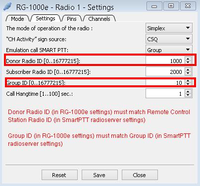
28 1. RG-1000e Customer Programming Software (RG-1000e CPS) 27 SmartPTT 9.2 and earlier versions don't support native RG-1000e Radio I\O mode. For using SmartPTT 9.2 and earlier versionswith non-mototrbo donor radios it needs to turn-on and configure SmartPTT Emulation Call feature in RG-1000e settings Emulation call SMART PTT: set Group. Donor Radio ID: specify desirable ID. Attention! Donor Radio ID must match corresponding Remote control Station Radio ID (in SmartPTT Radioserver settings). Subscriber Radio ID: specify desirable ID that will be used for incoming calls as Caller ID. Group ID: specify desirable ID. Attention! Group ID must match corresponding Group ID (in SmartPTT Radioserver settings). Note! PTT button for specified Talkgroup ID should be used for making outgoing calls from SmartPTT Dispatcher console (via RG-1000e with connected non-mototrbo radio).
29 1. RG-1000e Customer Programming Software (RG-1000e CPS) Call Hangtime: set 1 sec. 28
. - pin 25: 0 V.")
30 1. RG-1000e Customer Programming Software (RG-1000e CPS) The Pins tab defines Radio 1(2) port pings settings. Recommended pins settings are: - pin 3: Output control PTT. - pin 17: Input carrier detect (CSQ \COR\PL detect\tg detect). - pin 25: 0 V. The Channels tab. Is not used for SmartPTT operations. 29

31 1. RG-1000e Customer Programming Software (RG-1000e CPS) 30 Audio RX The Audio RX window defines settings of the RG-1000e GATEWAY analog inputs. To open the Audio RX window, double-click Audio RX on the RG-1000e panel in the Radio section. Inputs: o 1: It is a line balanced\unbalanced input that is connected to the radio station Rx Audio output.recommended attenuation setting is 0 db and Differential input is On. o 2: It is a unbalanced input with external attenuator and additional amplifier for receiver signal input from non typical audio sources Amplifier: If it is required, it can provide the input signal gain. Rated input signal level without gain is 330 mv (unbalanced mode). Recommended gain value is 9 db. Input overload control is performed on the base of input signal meter in the Monitor > Audio input section of the corresponding interface.
32 1. RG-1000e Customer Programming Software (RG-1000e CPS) 31 Audio encoder RX The Audio encoder RX windows define the settings of the input audio signal coding (for Radio 1 and Radio 2 independently). To open the Audio encoder RX window, double-click Audio encoder RX on the RG-1000e panel in the Radio 1 or Radio 2 section. Control: o Disable (CSQ and VOX both boxes are uncheck ed): RG-1000e continuously streams audio to IP network. o CSQ: RG-1000e streams audio to IP network only if a connected donor radio sends CSQ signal to RG-1000e. CSQ is recommended setting and used to reduce IP traffic. For proper CSQ signal processing you should: - for Radio 1(2) port Mototrbo DM mode: select Control Mode CSQ - USB interface (see Radio 1(2) settings - Settings tab) - for Radio 1(2) port I\O mode: set one pin as Input Carrier Detect (see Radio 1(2) settings - Pins tab) and connect this pin to a corresponded pin on connected control station acc. connector. o VOX: RG-1000e streams audio to IP network if RG-1000e internal VOX trigger has Active status. The encoding mode: o Mu-Law / A-Law 64 k bps: The audio processing by G.711 standard. SmartPTT recommend setting is u-law 64 kbps. Duration audio package: The total duration of audio data in the generated packet, recommended setting is 20 ms.
33 1. RG-1000e Customer Programming Software (RG-1000e CPS) 32 RG-1000e internal VOX may be used if RG-1000e is pre-programmed to interact with non-mototrbo contral station that doesn't have on acc. connector such signals as CSQ\PL Detect\TG Detect. Note! RG-1000e internal VOX can not be used if incoming audio signal sourced directly from FM demodulator. RG-1000e internal VOX may work properly if incoming audio signal is qualified as "squelched". Also RG-1000e internal VOX may operate with audio signal sourced from donor radio speaker <+> and <-> signal lines. In this case a donor radio speaker volume should be fixed using suitable programming software. Detector of signal level, VOX: On-Off internal VOX. VOX status for signal detector: Allows to use internal VOX status as pseudo CSQ signal status (see corresponding settings for I\O mode: Radio 1(2) settings - Setting, CH Activity signal source) Signal level ON: Threshold On audio level, mv. Detect time: Threshold On time duration, ms. If incoming audio level is more than threshold On audio level for the period of time more than Threshold On time duration: internal VOX trigger gets Active status. Signal level OFF: Threshold Off audio level, mv. Release time: Threshold Off time duration, ms. If incoming audio level is lower than threshold On audio level for the period of time more than Threshold Off time duration: internal VOX trigger gets Inactive status. Note! Recommended correlation Signal level ON \ Signal level OFF is 3:1. Note! Recommended minimum Release time is 500 ms. Figure below shows recommend Audio encoder RX settings for MTM5**** donor radios.

34 1. RG-1000e Customer Programming Software (RG-1000e CPS) 33 Audio TX The Audio TX window defines the analog output parameters. Audio TX enables the connection of signals from different audio channels to the output. To open the Audio TX window, double click Audio TX on the RG-1000e panel in the Radio section. Recommended settings for control stations are 0 db for Radio 1 TX output and 7 db of gain value for Amplifier.
35 1. RG-1000e Customer Programming Software (RG-1000e CPS) Audio TxH The Audio Tx H window defines the analog parameters for audio outputs with high output impedance. Selector signals enables the connection of signals from different audio channels to the output. To open the Audio Tx H window, double click Audio Tx H on the RG-1000e panel in the Radio section. For regular Mototrbo\SmartPTT operations keep all boxes unchecked. 34
36 1. RG-1000e Customer Programming Software (RG-1000e CPS) 35 Encoder audio L-b The Encoder audio L-b windows define the settings of loop-back audio stream using for voice traffic sharing between multiple SmartPTT radioservers (for Radio 1 and Radio 2 independently). Usually this feature in nor used for regular SmartPTT operations. Just keep settings as it shown on the figure below.
37 1. RG-1000e Customer Programming Software (RG-1000e CPS) Other The Other section contains the following parameters: Audio decoders TX: It serves for operation mode control of the audio decoder of the corresponding IP channel. Recorder: It serves for operation mode control of the recorder of the corresponding IP channel.
.")
38 1. RG-1000e Customer Programming Software (RG-1000e CPS) 37 Audio decoder TX The Audio decoders TX windows define buffer sizes of audio decoders for jitter compensation of received audio data packets (for each IP Channel independently). To open the desirable IP Channel Decoder microphone window, double-click Audio decoders TX on the RG1000e panel in the Other section, and next double-click required Channel for setting. In case of big packet jitter in the IP network, it is recommended to change the audio decoder parameters of working IP channels: Managing the duration of the buffer: Select Fixed. The duration of the buffer: Select 180 ms.

39 1. RG-1000e Customer Programming Software (RG-1000e CPS) 38 Recorder The Recorder section combines the control parameters and regulators of audio signals transmitted to output for communications recorder connection. Note: Attention! The given settings do not influence on the interaction of RG-1000e GATEWAY and radioserver, they are necessary only for third-party devices connection to the RG-1000e GATEWAY. To open the Recorder window, double-click Recorder on the RG-1000e panel. The Control tab provides a choice of digital signals for audio signal enabling/disabling. It is recommended to select all check boxes in the Radio 1, the control signals and Radio 2, the control signals sections of the Control tab. The Signals tab contains the selector of audio signals incoming to the recorder and variable output amplifier with control interval from 0 to 9 Db. The selector channels have variable attenuators with control interval from -78,3 to 0 Db.

40 1. RG-1000e Customer Programming Software (RG-1000e CPS) 39 To forward to Recorder port audio only from Radio Port, select the Receiver 1 and Microphone 1 check boxes only. To record audio from Accessory Connector, select the Receiver 2 and Microphone 2 check boxes only. You may keep signal levels settings with 0 db of gain value, as it is shown on the picture above.

41 1. RG-1000e Customer Programming Software (RG-1000e CPS) Statistics section This section provides useful technical information which helps to perform RG-1000e GETAWAY implementation. The Statistics section combines statistic reports on the operation of the following components: controller, interfaces for connection of radio station or control terminal, network interface, and IP channels. To start/stop reporting from the RG-1000e GATEWAY, click the Start or Stop button in the window of corresponding report. The statistic data is updated periodically at 1 second intervals. Statistic counters are of 32 bits, if the counter is overflowed, the counter will be reset and it will continue to count. To reset the counter to "0", click Reset in the report window.

42 1. RG-1000e Customer Programming Software (RG-1000e CPS) 41 Common The Common window contains the reports on the loading status of the RG-1000e GATEWAY processors and on network interface status. To open the Common window, double-click Common on the RG-1000e panel in the Statistics section. Click Start to see real-time Common information. Click Stop to terminate monitoring process.

43 1. RG-1000e Customer Programming Software (RG-1000e CPS) 42

44 1. RG-1000e Customer Programming Software (RG-1000e CPS) 43 Radio The Radio window contains the reports on the interface operation mode, connected IP channels and other data on operation. To open the Radio window, double-click the required Radio on the RG-1000e panel in the Statistics section. Click Start to see real-time information about the selected Radio. Click Stop to terminate monitoring process. Figure above shows: - Radio 1 port operates in Mototrbo DM mode, - Radio 1 post has active connection with a remote node via IP channel 1, - Radio 1 port has active connection with the connected radio, - Radio 1 port has active connection with a remote application, - Radio 1 is detecting incoming call activity from connected Mototrbo radio.
45 1. RG-1000e Customer Programming Software (RG-1000e CPS) Network The Network window contains the information on: the operation of network interface driver, the operation of network protocols, and received and transmitted data for the Radio interfaces. To open the Network window, double-click Network on the RG-1000e panel in the Statistics section. Click Start to see real-time information about the Network. Click Stop to terminate monitoring process. 44


46 1. RG-1000e Customer Programming Software (RG-1000e CPS) 45

47 1. RG-1000e Customer Programming Software (RG-1000e CPS) 46

48 1. RG-1000e Customer Programming Software (RG-1000e CPS) 47 IP channel The IP Channel window contains the report on the operation of data transmission protocol and audio decoder of the corresponding IP channel. To open the IP Channel window, double-click the required IP Channel on the RG-1000e panel in the Statistics section. Click Start to see real-time information about the IP Channel. Click Stop to terminate monitoring process.


49 1. RG-1000e Customer Programming Software (RG-1000e CPS) 48
50 1. RG-1000e Customer Programming Software (RG-1000e CPS) 49

51 1. RG-1000e Customer Programming Software (RG-1000e CPS) Monitor section The Monitor section combines the windows of input and output oscillograms of the RG-1000e GATEWAY interface audio signals. The oscillograms are output in real time at sampling frequency of 8 khz. To open the oscillogram window, click the required Audio input or Audio output on the RG-1000e panel in the Monitor section. You can see the example of the oscillogram for Audio input 1 below. 50

52 1. RG-1000e Customer Programming Software (RG-1000e CPS) Info section The RG-1000e - Info window contains the RG-1000e GATEWAY model description, serial number and numbers of processor software versions. To open the RG-1000e - Info window, double-click Info on the RG-1000e panel.

53 2. Radio settings Radio settings This section describes the radio settings that are directly related to the interaction with a RG-1000e GATEWAY and does not cover all other radio settings. 2.1 MOTOTRBO settings Firmware version of the MOTOTRBO radio connected to a RG-1000e GATEWAY can't be older than R Before connecting the MOTOTRBO radio to the RG-1000e GATEWAY in the MOTOROLA DM mode, it is required to configure the following radio parameters in MOTOTRBO CPS: 1. Set up the accessory connector modes. Click the Accessories tab in the radio settings and in the Top section specify the following values: Select Filtered Squelch in the RX Audio Type field, and Select Rear PC & Audio in the Cable Type field. 2. In the Top section of the Accessory tab specify the following values for Pin #17:

54 2. Radio settings 53 Select Ext Mic PTT in the Feature column, and Select Low in the Active Level column. 3. Click the Network tab in the radio settings. In the Radio Network section, select Via USB in the Forward to PC field.

55 2. Radio settings In the Network tab, ensure that the UDP ports values of the Telemetry, ARS, TMS and Location services match the corresponding values, configured in the gateway (see the Settings tab of the Settings subsection in the Radio section of the Controller panel). Check the values in the following fields: the Telemetry UDP Port field in the Radio Network section, the ARS UDP Port field in the Services section, the TMS UDP Port field in the Services section, and

56 2. Radio settings the Location Server UDP Port field in the Control Station section. 55

57 2. Radio settings 56

58 2. Radio settings 2.2 non-mototrbo settings Pictures below show proper radio settings for CDM\PRO legacy analog radios, legacy XPR 8300\XPR8400 and XIRR8200 repeaters. CDM\PRO mobile radios 1. Radio configuration menu, Accessory Configuration tab, Select Flat Audio in the Rx Audio Type, Select Ext Mic Audio in the External PTT Audio Source, Set 100 msec in the Accessory Debounce Duration. 2. Radio configuration menu, Accessory Pins tab, Set pin 3 - External Mic PTT, active level low, Set pin 4 - PL and CSQ Detect\Talkgroup Detect, active level low, Optionally pins 6, 8, 12, 14 may be used for channel switching 57

59 2. Radio settings Set pin 6 - Channel Select 1, active level low, Set pin 8 - Channel Select 2, active level low, Set pin 12 - Channel Select 3, active level low, Set pin 14 - Channel Select 4, active level low. 58

60 2. Radio settings XPR 8300\XPR8400\XIRR8200 repeaters (valid only for analog mode) Accessory menu Select Filtered Squelch in the Audio Type, Select External PTT in the Audio Priority, Set 100 msec in the Debounce Duration, Set pin 17 - External Mic PTT, active level low, Set pin 19 - PL\Talkgroup Detect, active level low. Optionally pins 20, 21, 22 may be used for channel switching. 59
61 3. SmartPTT Radioserver settings SmartPTT Radioserver settings The SmartPTT Radioserver can be configured in different ways to work with the RG-1000e GATEWAY. It depends on the topology of the MOTOTRBO network to which the radioserver is connected. 3.1 Interaction with Mototrbo remote control stations in direct communication mode or with the use of single repeater (IP Site Connect network) Radio network topologies and examples of SmartPTT dispatching systems for this radioserver configuration are described in details in the "RG-1000e Remote Gateway" user guide. See the following sections in the guide: "Direct Mode communication between the radio stations (Talkaround) in digital or analog mode", and "System topology with the use of a single repeater or the IP Site Connect network". For connection to each of the pre-configured IP channels on the RG-1000e GATEWAY, a separate connection on the radioserver (remote MOTOTRBO control station) should be created. To create the connection to the RG-1000e GATEWAY in the Direct Mode communication between the radio stations or for working with the repeater, configure the following settings in SmartPTT Radioserver Configurator: 1. Right click Control Stations in the setting tree of SmartPTT Radioserver Configurator. 2. Click Add > Remote MOTOTRBO control station.
62 3. SmartPTT Radioserver settings In the window that opens specify the parameters of the connection to the remote control station. Active: Activates the connection to the remote control station. To disable the remote control station from the connection list, clear the Active check box. Name: Remote control station arbitrary name.
63 3. SmartPTT Radioserver settings 62 Remote gateway IP address: Gateway network IP address. The IP address in this field must match the value specified in the settings of the gateway IP channel for this remote control station. See in RG-1000e CPS, the corresponding IP channel window in the Network section. XCMP port: The gateway port. The XCMP port in this field must match the value specified in the corresponding field in RG-1000e CPS. See the Port XCMP protocol field in the IP channel window of the Network section. Local interface: The local interface used for connection to the RG-1000e GATEWAY. Radio ID: Unique identifier of the remote control station. Radio ID is to be set in the range from 1 to CAI Network: CAI network identifier. To be set in the range from 1 to 126. Use the default value of 12. CAI Network for Groups: Group CAI network identifier. To be set in the range from 225 to 239. Use the default value of 225. Transmit Data Only: If selected, the remote control station is used for data transmit only and is not displayed in SmartPTT Dispatcher and is not available for voice calls. Allow Telephone Interconnect: Allows you to enable voice calls to telephone subscribers. GPS: Enables location service which provides coordinates of the subscribers, whose radios are equipped with a built-in GPS receiver. ARS: Enables registration service. When the radio powers up, the radio automatically registers with the server. Port 4005 is used as default. TMS: Enables the service for exchanging text messages between dispatchers and radio subscribers. Port 4007 is used by default. Telemetry Service: Enables the service responsible for transmitting and processing of telemetry signals between SmartPTT Dispatcher and subscriber stations. Port 4008 is used by default. Analog Call Hangtime: Virtual hangtime which is used for uniting analog calls into one. This was done to not overload the event log with too many records of analog calls. During this hangtime the channel is not reserved, anyone can start transmitting. The hangtime applies only if the remote control station is configured to operate in analog mode. GPS Transmission Mode: Allows you to select the way how to transmit location updates: as a data packet in multiple bursts or as a single CSBK (Control Signaling Block). This time select Data. Set local ports: Local ports that can be used for connection to the RG-1000e GATEWAY, if the default ports of the corresponding services are already in use. By default the system occupies local ports automatically, but you can define them manually. 4. Add or edit the channels of the remote control station in the Control Station Channels window. These settings allows remote switching between the control station channels and must match with the radio settings in the MOTOTRBO CPS.
64 3. SmartPTT Radioserver settings 63 Name: Channel alias visible to SmartPTT Dispatcher. Zone: Serial number of a channel group. Information on the maximum possible number of zones and radio station channels is shown in the following table. Model Maximum number of Maximum number of Maximum total number of zones channels per zone channels Mobile radio station with display Mobile radio station with seven-segment display Channel: Channel sequence number. : Selected channel will be set at the control station, when you start the radioserver. Copy: Copies added channels of the remote control station to the clipboard Paste: Pastes copied channels of the remote control station from the clipboard. Add: Adds a new channel. Remove: Deletes the channel from the list. To edit channel name, zone or channel number, place the cursor on the corresponding field and make changes. Note: The maximum number of zones and channels of the MOTOTRBO control station depends on the model and version of the parameter block. 5. In the Control Station Talkgroups window, add or edit the talkgroups, which the dispatcher(s) may use for making a call via the remote control station.

65 3. SmartPTT Radioserver settings 64 To add a talkgroup, click Add. To add All Call (is used in profiles), click All Calls. To change the order of groups in the list, use the Up and Down arrows. The order defined in the window will be used in SmartPTT Dispatcher. Name: Talkgroup alias displayed by the control station. ID: Talkgroup unique identifier used during communications. To be set in the range from 1 to Copy: Copies added groups (their names and IDs) to the clipboard. Paste: Pastes copied groups from the clipboard. Remove: Deletes the selected talkgroup. To edit talkgroup name or ID, set the cursor on the corresponding field and make changes. 6. To select audio devices and set up VoIP parameters, click Audio in the setting tree of SmartPTT Radioserver Configurator. At that, the Audio Settings window will open. The Active check box activates transmission and receiving of the audio signals for the remote control station. Codec: Outgoing audio stream compression method. The recommended value is CCITT u-law.
66 3. SmartPTT Radioserver settings 65 Format: Sampling frequency of an outgoing audio stream and the RTP packet size. The recommended value is 8000 Hz, 20 ms, 64 (86) k bps. 7. If you need to create more than one connection to the remote control stations, repeat steps 1 to 6 for each new remote control station.

67 3. SmartPTT Radioserver settings Interaction with Mototrbo remote control stations in the Capacity Plus Legacy mode Radio network topology and the example of SmartPTT dispatching system for this radioserver configuration are described in details in the "RG-1000e Remote Gateway" user guide. See the section "Example of system topology in the Capacity Plus Legacy trunking network". The parameters of the connection to the remote control stations in the Capacity Plus Legacy mode are configured in the Capacity Plus Systems section of SmartPTT Radioserver Configurator. This guide does not cover the common settings of the radio networks configuration. For more information about the Capacity Plus systems configuration see the "SmartPTT Radioserver Configurator" software help file. To add connection to the remote control stations in the Capacity Plus Legacy mode, configure the following settings the TX Stations menu item of SmartPTT Radioserver Configurator: 1. Right click TX Stations, then click Add > Remote MOTOTRBO control station. 2. Specify the parameters of connection to the remote control station as it is described in the previous section. 3. If you need to create more than one connection to the remote control stations, repeat steps 1 to 2 for each new remote control station.
68 3. SmartPTT Radioserver settings Interaction with Mototrbo remote control stations in the NAI Capacity Plus and NAI Linked Capacity Plus hybrid modes Radio network topologies and examples of SmartPTT dispatching systems for this radioserver configuration are described in details in the "RG-1000e Remote Gateway" user guide. See the following sections in the guide: "Example of system topology in the Capacity Plus trunking network with data transmission via the NAI protocol (hybrid mode)", and "Example of system topology in the Linked Capacity Plus trunking network with data transmission via the NAI protocol (hybrid mode)". The parameters of the connection to the remote control stations in the NAI Capacity Plus and NAI Linked Capacity Plus modes are configured in the corresponding sections in SmartPTT Radioserver Configurator. This guide does not cover the common settings of the radio networks configuration. For more information about the configuration of the NAI - Capacity Plus and NAI - Linked Capacity Plus systems see the "SmartPTT Radioserver Configurator" software help file. To add connection to the remote control stations in the NAI Capacity Plus and NAI Linked Capacity Plus modes, configure the following settings in the NAI Systems section of SmartPTT Radioserver Configurator: 1. In the NAI - Capacity Plus or NAI - Linked Capacity Plus network general settings, select the Voice transmission check box and select Control Stations in list (applicable to the SmartPTT PLUS systems). If you use the SmartPTT Enterprise systems, skip this step.


69 3. SmartPTT Radioserver settings In the Slot menu item of the NAI - Capacity Plus or NAI - Linked Capacity Plus sections, right click Control Stations, then click Add > Remote MOTOTRBO control station. 3. Specify the parameters of connection to the remote control station as it is described in the previous section.
70 3. SmartPTT Radioserver settings If you need to create more than one connection to the remote control stations, repeat steps 1 to 2 for each new remote control station.
 you should configure the following settings in SmartPTT Radioserver")
71 3. SmartPTT Radioserver settings Interaction with non-mototrbo remote control stations (remote I\O control staition), for SmartPTT 9.3 and later To create the connection to the RG-1000e GATEWAY for interaction with non-mototrbo control station (RG-1000e I\O mode) you should configure the following settings in SmartPTT Radioserver Configurator: 1. Right click Control Stations in the setting tree of SmartPTT Radioserver Configurator. 2. Click Add > Remote I\O Control Station. 3. In the window that opens specify the parameters of the connection to the remote control station.

72 3. SmartPTT Radioserver settings 71 Active: Activates the connection to the remote control station. To disable the remote control station from the connection list, clear the Active check box. Name: Remote control station arbitrary name. This name will be shown on SmartPTT Dispatcher console. Remote gateway IP address: Gateway network IP address. The IP address in this field must match the value specified in the settings of the gateway IP channel for this remote control station. See in RG-1000e CPS, the corresponding IP channel window in the Network section. XCMP port: The gateway port. The XCMP port in this field must match the value specified in the corresponding field in RG-1000e CPS. See the Port XCMP protocol field in the IP channel window of the Network section. Serial number: Radio serial number. Just for your reference, for instance Local interface: The local Ethernet interface used for connection to the RG-1000e GATEWAY. Talkgroup name: Put talkgroup name. Just for your reference, for instance All Call. TX Criteria: Determines when the radio is allowed to be transmitted. Always:the radio will always. Channel Free: the radio will check for an idle channel prior to allowing a transmission. TX Time-Out Timer, s: Continuous radio transmission timeout. After this time the transmission is interrupted. Call Hangtime, ms: Virtual hangtime which is used for uniting calls into one. This was done to not overload the event log with too many records of calls. During this hangtime the channel is not reserved, anyone can start transmitting. Set local ports: Local ports that can be used for connection to the RG-1000e GATEWAY, if the default ports of the corresponding services are already in use. By default the system occupies local ports automatically, but you can define them manually. 4. Add or edit the channels of the remote control station in the Control Station Channels window. These settings allows remote switching between the control station channels and must match with the radio settings in the remote non-mototrbo control station. Name: Channel alias visible to SmartPTT Dispatcher. Channel: Channel sequence number. : Selected channel will be set at the control station, when you start the radioserver.

73 3. SmartPTT Radioserver settings 72 Copy: Copies added channels of the remote control station to the clipboard. Paste: Pastes copied channels of the remote control station from the clipboard. Add: Adds a new channel. Remove: Deletes the channel from the list. To edit channel name place the cursor on the corresponding field and make changes. 5. To select audio devices and set up VoIP parameters, click Audio in the setting tree of SmartPTT Radioserver Configurator. At that, the Audio Settings window will open. The Active check box activates transmission and receiving of the audio signals for the remote control station. Codec: Outgoing audio stream compression method. The recommended value is CCITT u-law. Format: Sampling frequency of an outgoing audio stream and the RTP packet size. The recommended value is 8000 Hz, 20 ms, 64 (86) k bps. 7. If you need to create more than one connection to the remote control stations, repeat steps 1 to 6 for each new remote control station.

74 3. SmartPTT Radioserver settings Interaction with non-mototrbo remote control stations (using SmartPTT Call Emulation), for SmartPTT 9.2 and earlier To create the connection to the RG-1000e GATEWAY, that is pre-programmed to interact with non-mototrbo control stations, using SmartPTT Call Emulation feature, configure the following settings in SmartPTT Radioserver Configurator: 1. Right click Control Stations in the setting tree of SmartPTT Radioserver Configurator. 2. Click Add > Remote MOTOTRBO control station.
75 3. SmartPTT Radioserver settings In the window that opens specify the parameters of the connection to the remote control station. Active: Activates the connection to the remote control station. To disable the remote control station from the connection list, clear the Active check box. Name: Remote control station arbitrary name. This name will be shown on SmartPTT Dispatcher console.

76 3. SmartPTT Radioserver settings 75 Remote gateway IP address: Gateway network IP address. The IP address in this field must match the value specified in the settings of the gateway IP channel for this remote control station. See in RG-1000e CPS, the corresponding IP channel window in the Network section. XCMP port: The gateway port. The XCMP port in this field must match the value specified in the corresponding field in RG-1000e CPS. See the Port XCMP protocol field in the IP channel window of the Network section. Local interface: The local Ethernet interface is used for connection to the RG-1000e GATEWAY. Radio ID: Unique identifier of the remote control station. In the case when RG-1000e GATEWAY interacts with non-mototrbo control stations, using for call processing SmartPTT Call Emulation feature, Radio ID must match corresponding ID in RG-1000e settings. CAI Network: CAI network identifier. Set 12. CAI Network for Groups: Group CAI network identifier. Set 225. Boxes Transmit Data Only, Allow Telephone Interconnect, GPS, ARS, TMS, Telemetry Service, Set local ports should be unchecked. Analog Call Hangtime: Set 1000 ms. 4. Add or edit the channels of the remote control station in the Control Station Channels window. These settings allows remote switching between the control station channels and must match with the non-mototrbo radio settings.


77 3. SmartPTT Radioserver settings 76 Name: Channel alias visible to SmartPTT Dispatcher. Zone: Serial number of a channel group. Use Zone 1. Channel: Channel sequence number. : Selected channel will be set at the control station, when you start the radioserver. Copy: Copies added channels of the remote control station to the clipboard. Paste: Pastes copied channels of the remote control station from the clipboard. Add: Adds a new channel. Remove: Deletes the channel from the list. To edit channel name, or channel number, place the cursor on the corresponding field and make changes. 5. In the Control Station Talkgroups window, add just one talkgroup, which the dispatcher(s) may use for making outgoing calls via the remote non-mototrbo control station. To add a talkgroup, click Add. Remove: Deletes the selected talkgroup. Name: Talkgroup alias displayed by the control station.to edit talkgroup name or ID, set the cursor on the corresponding field and make changes.


78 3. SmartPTT Radioserver settings 77 ID: Talkgroup unique identifier used during communications. In the case when RG-1000e GATEWAY interacts with non-mototrbo control stations, using for call processing SmartPTT Call Emulation feature, the talkgroup identifier must match corresponding ID in RG-1000e settings. 6. To select audio devices and set up VoIP parameters, click Audio in the setting tree of SmartPTT Radioserver Configurator. At that, the Audio Settings window will open.
79 3. SmartPTT Radioserver settings 78 The Active check box activates transmission and receiving of the audio signals for the remote control station. Codec: Outgoing audio stream compression method. The recommended value is CCITT u-law. Format: Sampling frequency of an outgoing audio stream and the RTP packet size. The recommended value is 8000 Hz, 20 ms, 64 (86) k bps. 7. If you need to create more than one connection to the remote control stations, repeat steps 1 to 6 for each new remote control station.
80 4. Radio 1(2) port configuration samples 4. Radio 1(2) port configuration samples Figures below show Radio 1(2) port setting for interaction RG-1000e with different donor radios. Hope it makes RG-1000e implementation process easier and faster. Shown Radio 1(2) port settings may be considered as recommended. At the same time settings may vary depends on a project technical requirements. 79


81 4. Radio 1(2) port configuration samples 4.1 Mototrbo, Radio 1(2) port settings 80

82 4. Radio 1(2) port configuration samples 81

83 4. Radio 1(2) port configuration samples 82
84 4. Radio 1(2) port configuration samples 83
85 4. Radio 1(2) port configuration samples 4.2 APX\XTL, Radio 1(2) port setting, SmartPTT 9.3 or later 84

86 4. Radio 1(2) port configuration samples 85
87 4. Radio 1(2) port configuration samples 86
88 4. Radio 1(2) port configuration samples 87
89 4. Radio 1(2) port configuration samples 88
90 4. Radio 1(2) port configuration samples APX\XTL, Radio 1(2) port settings, SmartPTT 9.2 or earlier
 port")

91 4. Radio 1(2) port configuration samples 90
92 4. Radio 1(2) port configuration samples 91
93 4. Radio 1(2) port configuration samples 92
94 4. Radio 1(2) port configuration samples 93
95 4. Radio 1(2) port configuration samples MTM, Radio 1(2) port settings, SmartPTT 9.3 or later
 port")

96 4. Radio 1(2) port configuration samples 95
97 4. Radio 1(2) port configuration samples 96

98 4. Radio 1(2) port configuration samples 97
 port settings, SmartPTT 9.")
99 4. Radio 1(2) port configuration samples 4.5 MTM, Radio 1(2) port settings, SmartPTT 9.2 or earlier 98
100 4. Radio 1(2) port configuration samples 99

101 4. Radio 1(2) port configuration samples 100
102 4. Radio 1(2) port configuration samples 101
103 4. Radio 1(2) port configuration samples SLR5500\XPR8300\XPR8400\XIRR8200, Radio 1(2) port settings, SmartPTT 9.3 or later

104 4. Radio 1(2) port configuration samples 103
105 4. Radio 1(2) port configuration samples 104

106 4. Radio 1(2) port configuration samples 105

107 4. Radio 1(2) port configuration samples SLR5500\XPR8300\XPR8400\XIRR8200, Radio 1(2) port settings, SmartPTT 9.2 or earlier

108 4. Radio 1(2) port configuration samples 107
109 4. Radio 1(2) port configuration samples 108
110 4. Radio 1(2) port configuration samples 109

111 Appendix I RG-1000e driver installation Appendix I RG-1000e driver installation To install RG-1000 driver perform the following actions: 1. Download from Zagid 2.3 softool. 2. Locate Zagid 2.3 to a desirable folder. Installation is not required. 3. Connect RG-1000e to PC USB port and turn-on RG-1000e. 4. Navigate to PC Control panel and open PC Device Manager. You may see Other devices - ATIS M


112 Appendix I RG-1000e driver installation 5. Run Zagid and select target device ATIS M Check on Edit box. 7. Delete ATIS M-300 and type RG-1000e. 111

. 9.")

113 Appendix I RG-1000e driver installation 8. Select target driver libusb-win32 (v ). 9. Click Install Driver. 10. If everything is ok you should see this pop-up message. 112

114 Appendix I RG-1000e driver installation 11. Open PC Device Manager. You may see RG-1000e device. 113
"Terminal RG-1000" Customer Programming Software. User Guide. August 2016 R4.3
 "Terminal RG-1000" Customer Programming Software User Guide August 2016 R4.3 Table of Contents Table of Contents Introduction 2 3 1.1 Software installation 3 1.2 Connecting the RG-1000 GATEWAYs to the
Customer Programming Software RG-1000e (CPS RG-1000e) User Guide. October 2017 R2.0
 User Guide. October 2017 R2.0") Customer Programming Software RG-1000e (CPS RG-1000e) User Guide October 2017 R2.0 Table of Contents Table of Contents Foreword 2 Revision history 3 Introduction 4 5 1.1 Software installation 5 1.2 Connecting
Customer Programming Software RG-1000e (CPS RG-1000e) User Guide October 2017 R2.0 Table of Contents Table of Contents Foreword 2 Revision history 3 Introduction 4 5 1.1 Software installation 5 1.2 Connecting
Customer Programming Software RG-1000e (CPS RG-1000e) User Guide. June 2018 R2.2.2 v2
 User Guide. June 2018 R2.2.2 v2") Customer Programming Software RG-1000e (CPS RG-1000e) User Guide June 2018 R2.2.2 v2 Table of Contents Table of Contents Foreword 3 Revision history 4 Introduction 5 1. RG-1000e Customer Programming Software
Customer Programming Software RG-1000e (CPS RG-1000e) User Guide June 2018 R2.2.2 v2 Table of Contents Table of Contents Foreword 3 Revision history 4 Introduction 5 1. RG-1000e Customer Programming Software
Version 8.8 Linked Capacity Plus. Configuration Guide
 Version 8.8 Linked Capacity Plus February 2016 Table of Contents Table of Contents Linked Capacity Plus MOTOTRBO Repeater Programming 2 4 MOTOTRBO Radio Programming 14 MNIS and DDMS Client Configuration
Version 9.1 SmartPTT Enterprise. Installation & Configuration Guide
 Version 9.1 SmartPTT Enterprise December 2016 Table of Contents Table of Contents 1.1 Introduction 3 1.2 Installation of the SmartPTT software 3 1.3 General SmartPTT Radioserver Configuration 7 1.4 SmartPTT
Version 9.1. Installation & Configuration Guide
 Version 9.1 SmartPTT PLUS November 2016 Table of Contents Table of Contents Introduction 2 Installation of the SmartPTT software 2 General SmartPTT Radioserver Configuration 6 SmartPTT Dispatcher Configuration
Version SmartPTT Enterprise. Installation and Configuration Guide
 Version 9.3.1 July 2018 Contents Contents 1 Introduction 4 2 Preliminary Actions 5 2.1 HDD Space Estimation 5 3 Installation of SmartPTT Software 7 4 General SmartPTT Radioserver Configuration 12 5 SmartPTT
Configuration Guide. Version 8.3
 Capacity Plus Configuration Guide Version 8.3 Table of Contents 1 Table of Contents 1 Introduction 2 2 Brief Information on Use of Control Stations 4 3 6 3.1 Programming Repeter 7 3.1.1 Master Repeater
Version 9.2. SmartPTT PLUS. Capacity Max Configuration Guide
 Version 9.2 Configuration Guide Januar 2018 Contents Contents 1 3 1.1 Configuring 5 1.2 Configuring Trunk Controller 9 1.3 Configuring MNIS Data Gateway 15 1.4 Configuring MNIS VRC Gateway 22 1.5 Configuring
Version 9.1 SmartPTT Monitoring
 Version 9.1 SmartPTT Monitoring December 2016 Table of Contents Table of Contents 1.1 Introduction 2 1.2 Installation of the SmartPTT software 2 1.3 General SmartPTT Radioserver Configuration 6 1.4 SmartPTT
Version 9.3. SmartPTT Enterprise. Release Notes
 Version 9.3 June 2018 New Features 2 New Features Backhaul Repeater Chains supports the Backhaul Repeater Chains (BRC) feature in digital conventional radio systems. Both legacy IP Site Connect and IP
CTI Products. RadioPro IP Gateway. Installation Guide. Document # S For Version 8 Software
 CTI Products RadioPro IP Gateway Installation Guide Document # S2-61781-809 For Version 8 Software A newer version of this document may be available. Please check the accompanying CD or www.ctiproducts.com
TRBOnet Enterprise. Linked Capacity Plus. Deployment Guide. Internet. US Office Neocom Software Jog Road, Suite 202 Delray Beach, FL 33446, USA
 TRBOnet Enterprise Linked Capacity Plus Deployment Guide World HQ Neocom Software 8th Line 29, Vasilyevsky Island St. Petersburg, 199004, Russia US Office Neocom Software 15200 Jog Road, Suite 202 Delray
TRBOnet Mobile. User Guide. for ios. Version 1.8. Internet. US Office Neocom Software Jog Road, Suite 202 Delray Beach, FL 33446, USA
 TRBOnet Mobile for ios User Guide Version 1.8 World HQ Neocom Software 8th Line 29, Vasilyevsky Island St. Petersburg, 199004, Russia US Office Neocom Software 15200 Jog Road, Suite 202 Delray Beach, FL
TRBOnet Enterprise. Capacity Plus. Deployment Guide. Internet. US Office Neocom Software Jog Road, Suite 202 Delray Beach, FL 33446, USA
 TRBOnet Enterprise Capacity Plus Deployment Guide World HQ Neocom Software 8th Line 29, Vasilyevsky Island St. Petersburg, 199004, Russia US Office Neocom Software 15200 Jog Road, Suite 202 Delray Beach,
DRG-Series. Digital Radio Gateway. Motorola MotoTRBO DMR. Interfacing Omnitronics DRG with Motorola MotoTRBO DMR Digital Radios
 DRG-Series Digital Radio Gateway Motorola MotoTRBO DMR Interfacing Omnitronics DRG with Motorola MotoTRBO DMR Digital Radios Digital Radio Supplement DRG-Series Supplement Interfacing Omnitronics DRG with
TRBOnet Mobile. User Guide. for Android. Version 2.0. Internet. US Office Neocom Software Jog Road, Suite 202 Delray Beach, FL 33446, USA
 TRBOnet Mobile for Android User Guide Version 2.0 World HQ Neocom Software 8th Line 29, Vasilyevsky Island St. Petersburg, 199004, Russia US Office Neocom Software 15200 Jog Road, Suite 202 Delray Beach,
TurboVUi Solo. User Guide. For Version 6 Software Document # S Please check the accompanying CD for a newer version of this document
 TurboVUi Solo For Version 6 Software Document # S2-61432-604 Please check the accompanying CD for a newer version of this document Remote Virtual User Interface For MOTOTRBO Professional Digital 2-Way
DRG-Series. Digital Radio Gateway. Kenwood NXDN Donor Radio (Tier-2) Interfacing Omnitronics DRG with Kenwood NXDN Donor Digital Radios (Tier-2)
 Interfacing Omnitronics DRG with Kenwood NXDN Donor Digital Radios (Tier-2)") DRG-Series Digital Radio Gateway Kenwood NXDN Donor Radio (Tier-2) Interfacing Omnitronics DRG with Kenwood NXDN Donor Digital Radios (Tier-2) Digital Radio Supplement DRG-Series Supplement Kenwood NXDN
DRG-Series Digital Radio Gateway Kenwood NXDN Donor Radio (Tier-2) Interfacing Omnitronics DRG with Kenwood NXDN Donor Digital Radios (Tier-2) Digital Radio Supplement DRG-Series Supplement Kenwood NXDN
TRBOnet Enterprise. Extended Range Direct Mode. Deployment Guide. Internet
 TRBOnet Enterprise Extended Range Direct Mode Deployment Guide World HQ Neocom Software 8th Line 29, Vasilyevsky Island St. Petersburg, 199004, Russia US Office Neocom Software 15200 Jog Road, Suite 202
TRBOnet Enterprise. IP Site Connect. Deployment Guide. Internet. US Office Neocom Software Jog Road, Suite 202 Delray Beach, FL 33446, USA
 TRBOnet Enterprise IP Site Connect Deployment Guide World HQ Neocom Software 8th Line 29, Vasilyevsky Island St. Petersburg, 199004, Russia US Office Neocom Software 15200 Jog Road, Suite 202 Delray Beach,
DRG-Series. Digital Radio Gateway. Hytera DMR USB Donor (Tier-2) Digital Radio Supplement
 Digital Radio Supplement") DRG-Series Digital Radio Gateway Hytera DMR USB Donor (Tier-2) Digital Radio Supplement DRG-Series Digital Radio Gateway Hytera DMR USB Donor (Tier-2) Digital Radio Supplement 2015 Omnitronics Pty Ltd.
DRG-Series Digital Radio Gateway Hytera DMR USB Donor (Tier-2) Digital Radio Supplement DRG-Series Digital Radio Gateway Hytera DMR USB Donor (Tier-2) Digital Radio Supplement 2015 Omnitronics Pty Ltd.
DRG-Series. Digital Radio Gateway. Tait P25 CCDI Tier-2 (TM9400 Series Mobile Radio) Digital Radio Supplement
 Digital Radio Supplement") DRG-Series Digital Radio Gateway Tait P25 CCDI Tier-2 (TM9400 Series Mobile Radio) Digital Radio Supplement DRG-Series Digital Radio Gateway Tait P25 CCDI Tier-2 (TM9400 Series Mobile Radio) Digital Radio
DRG-Series Digital Radio Gateway Tait P25 CCDI Tier-2 (TM9400 Series Mobile Radio) Digital Radio Supplement DRG-Series Digital Radio Gateway Tait P25 CCDI Tier-2 (TM9400 Series Mobile Radio) Digital Radio
INSTRUCTION MANUAL IP REMOTE CONTROL SOFTWARE RS-BA1
 INSTRUCTION MANUAL IP REMOTE CONTROL SOFTWARE RS-BA FOREWORD Thank you for purchasing the RS-BA. The RS-BA is designed to remotely control an Icom radio through a network. This instruction manual contains
Networks of any size and topology. System infrastructure monitoring and control. Bridging for different radio networks
 INTEGRATED SOLUTION FOR MOTOTRBO TM Networks of any size and topology System infrastructure monitoring and control Bridging for different radio networks Integrated Solution for MOTOTRBO TM Networks of
Hytera DMR Conventional Series Release Notes
 Hytera DMR Conventional Series Release Notes DMR Conventional Software Version: 6.00 Release Notes Version: 6.00.02 Software Release Date: 31-03-2014 Date: 31-03-2014 Copyright Information Hytera is the
Programming Parameter Guide
 Secure Wireless Microphone ELITE PRO Programming Parameter Guide rev:1 How to use Programmer: Start Programming application Runs On PC or Mac running Windows 7/10. To put Handset into programming mode,
Lynx. RoIP Gateway DISPATCH LYNX MOBILE. Optional serial ports provide remote control of radio configuration over the VoIP network.
 LYNX MOBILE Lynx DISPATCH RoIP TM SYSTEM Gateway LYNX TM ROIP GATEWAY OVERVIEW The Lynx system provides Radio over IP (RoIP) communications interoperability between radio base stations and VoIP networked
SafeMobile Radio Configuration
 SafeMobile Radio Configuration SafeMobile offers a world of wireless applications that help organizations better manage their mobile assets, fleet and personnel. For more information, see www.safemobile.com.
RG-1000e Remote Gateway. User Guide. March 2018 R2.2.1
 RG-1000e Remote Gateway March 2018 R2.2.1 Table of Contents Table of Contents Foreword 2 Revision history 3 Compliance with international standards 4 Introduction 5 1 System purpose 6 2 System structure
DMR Application Note Testing MOTOTRBO Radios On the R8000 Communications System Analyzer
 DMR Application Note Testing MOTOTRBO Radios On the R8000 Communications System Analyzer April 2 nd, 2015 MOTOTRBO Professional Digital Two-Way Radio System Motorola and MOTOTRBO is registered in the U.S.
SmartPTT PLUS 9.1. Radioserver Configurator User Guide
 Radioserver Configurator User Guide November 2016 Table of contents SmartPTT Radioserver Configurator 5 Settings 5 Radioserver 5 Redundant Radio Server 8 Licenses 14 Services 20 ARS 20 GPS 22 TMS 23 Telemetry
Application Note: DMR Application Note Testing MOTOTRBO Radios On the Freedom Communications System Analyzer
 : DMR Application Note Testing MOTOTRBO Radios On the Freedom Communications System Analyzer MOTOTRBO Professional Digital Two-Way Radio System Motorola and MOTOTRBO is registered in the U.S. Patent and
IP controller TRBOnet Swift Agent A002.M1
 IP controller TRBOnet Swift Agent A002.M1 Neocom software, LTd. Line 8, 29, Vasilyevsky Ostrov, Saint Petersburg, Russia, 199004 RU: +7 (812) 457-08 - 93 USA: +1 (872) 222-87 - 26 info@trbonet.com www.trbonet.com
Networks of any size and topology. System infrastructure monitoring and control. Bridging for different radio networks
 INTEGRATED SOLUTION FOR MOTOTRBO TM Networks of any size and topology System infrastructure monitoring and control Bridging for different radio networks Integrated Solution for MOTOTRBO TM Networks of
Introduction... 3 Programming the Pyramid Merlin or 2012/3012 MDT... 3 Programming the CDM1550LS+ Mobile Motorola CPS... 4 CDM1550LS+ Accessory Port
 COMMUNICATIONS Programming Instructions for: Motorola CDM1550LS+ LTR or Conventional For use with: Pyramid Communications Model 2017 Merlin/2012/3012 MDT Revision A August 2, 2006 1 Introduction... 3 Programming
Hytera. PD41X Patrol Management System. Installation and Configuration Guide
 Hytera PD41X Patrol Management System Installation and Configuration Guide Documentation Version: 01 Release Date: 03-2015 Copyright Information Hytera is the trademark or registered trademark of Hytera
INDEX...2 INTRODUCTION...3 IMPORTANT NOTES...3 INSTALLING THE SOFTWARE...3 ST-965 PROGRAMMING SOFTWARE...6
 ST-965 VX/D SMARTRUNK II & SMARTRUNK XPRESS Logic board Programming Software 2.9e User s Guide Revision R2.9 10/10/2008 INDEX INDEX...2 INTRODUCTION...3 IMPORTANT NOTES...3 INSTALLING THE SOFTWARE...3
CTI Products RadioPro Dispatch User Guide Document # S For Version 8 Software
 CTI Products RadioPro Dispatch Document # S2-61786-809 For Version 8 Software Contact Us Support, replacement part ordering, and service may be arranged by contacting our Cincinnati office. Parts for service
Programming Parameters - Feature Comparison : Rev 1
 Secure Wireless Microphone ELITE PRO CLASSIC Programming Parameters - Feature Comparison : Rev 1 How to use Programmer: Start Programming application Runs On PC or Mac running Windows 7/8. To put Handset
Testing Motorola P25 Conventional Radios Using the R8000 Communications System Analyzer
 Testing Motorola P25 Conventional Radios Using the R8000 Communications System Analyzer Page 1 of 24 Motorola CPS and Tuner Software Motorola provides a CD containing software programming facilities for
WPE 48N USER MANUAL Version1.1
 Version1.1 Security instructions 1. Read this manual carefully. 2. Follow all instructions and warnings. 3. Only use accessories specified by WORK PRO. 4. Follow the safety instructions of your country.
CTI Products RadioPro Dispatch Demo Installation and Test Drive Document # S For Version 8 Software
 CTI Products RadioPro Dispatch Demo Installation and Test Drive Document # S2-61570-801 For Version 8 Software Contact Us Support, replacement part ordering, and service may be arranged by contacting our
Hytera DMR Conventional Series
 Hytera DMR Conventional Series SIP Phone Gateway to Simultaneous Calls Application Notes Document version: 3.0 Date: 02-2015 Copyright Information Hytera is the trademark or registered trademark of Hytera
DRG-Series. Digital Radio Gateway. Icom IDAS MultiTrunk IP (Tier-3) Digital Radio Supplement
 Digital Radio Supplement") DRG-Series Digital Radio Gateway Icom IDAS MultiTrunk IP (Tier-3) Digital Radio Supplement DRG-Series Digital Radio Gateway Icom IDAS MultiTrunk IP (Tier-3) Digital Radio Supplement 2015 2017 Omnitronics
DRG-Series Digital Radio Gateway Icom IDAS MultiTrunk IP (Tier-3) Digital Radio Supplement DRG-Series Digital Radio Gateway Icom IDAS MultiTrunk IP (Tier-3) Digital Radio Supplement 2015 2017 Omnitronics
CAD-MF. PC-Based Multi-Format ANI & Emergency ANI Display Decoder. Manual Revision: Covers Firmware Revisions: CAD-MF: 1.
 CAD-MF PC-Based Multi-Format ANI & Emergency ANI Display Decoder Manual Revision: 2010-05-25 Covers Firmware Revisions: CAD-MF: 1.0 & Higher Covers Software Revisions: CAD: 3.21 & Higher Covers Hardware
F8101ALE User s Guide
 RadCommSoft, LLC F8101ALE User s Guide Aug 2017 1 F8101ALE User s Guide RadCommSoft, LLC presents F8101ALE F8101ALE is remote control software for the ICOM IC-F8101E, and includes a modem controller for
TRBOnet Enterprise 2.6 for MOTOTRBO Capacity Plus.
 TRBOnet Enterprise 2.6 for MOTOTRBO Capacity Plus Neocom Software Ltd: TRBOnet Team Software Products 7 products Custom Development Feature requests Software integration Support Team More than 200+ systems
DMRGateway Technical Overview INAD
 DMRGateway Technical Overview INAD Overview The goal Allow a user on the ASL analog network to communicate with a user on a DMR network. The networks DMR two time slot TDMA RF network IPSC Masters Peers
MOTOTRBO R1.8 Training Overview
 MOTOTRBO R1.8 Training Overview MOTOTRBO System Training Release1.8 MOTOROLA, MOTO, MOTOROLA SOLUTIONS and the Stylized M Logo are trademarks or registered trademarks of Motorola Trademark Holdings, LLC
MIDLAND PROGRAMING G14
 MIDLAND PROGRAMING G14 1. PROGRAMMING CAPABILITY Welcome to the MIDLAND Programming software! It s a programming software specifically designed for G14 and must be used in conjunction with the dedicated
WIRES-X Portable Digital Node Function. Instruction Manual
 Wide-Coverage Internet Repeater Enhancement System WIRES-X Portable Digital Node Function Instruction Manual Please read this Instruction Manual carefully for appropriate procedure. Preparation Procedure
Application Note: Testing P25 Conventional Radios Using the Freedom Communications System Analyzers
 : Testing P25 Conventional Radios Using the Freedom Communications System Analyzers FCT-1007A Motorola CPS and Tuner Software Motorola provides a CD containing software programming facilities for the radio
Disable Windows Sounds
 9/28/2017 - K3CT Disable Windows Sounds Users may want to disable the Windows Sounds so none of the Windows OS sounds are transmitted on the radio. Install the Icom Drivers, Select COM port, Disable Power
Quick Start Guide. RSP-Z2 Dual Channel Analog-IP Interface
 INTEROPERABILITY NOW Quick Start Guide RSP-Z2 Dual Channel Analog-IP Interface Designed and Manufactured by: JPS Interoperability Solutions 5800 Departure Drive Raleigh, NC 27616 919-790-1011 Email: sales@jpsinterop.com
DRG-Series. Digital Radio Gateway. Icom IDAS Conventional Wireline IP (Tier-2) (IC-FR5000/IC-FR6000 IDAS VHF/UHF Repeaters) Digital Radio Supplement
 (IC-FR5000/IC-FR6000 IDAS VHF/UHF Repeaters) Digital Radio Supplement") DRG-Series Digital Radio Gateway Icom IDAS Conventional Wireline IP (Tier-2) (IC-FR5000/IC-FR6000 IDAS VHF/UHF Repeaters) Digital Radio Supplement DRG-Series Digital Radio Gateway Icom IDAS Conventional
DRG-Series Digital Radio Gateway Icom IDAS Conventional Wireline IP (Tier-2) (IC-FR5000/IC-FR6000 IDAS VHF/UHF Repeaters) Digital Radio Supplement DRG-Series Digital Radio Gateway Icom IDAS Conventional
TRBOnet Enterprise/PLUS
 TRBOnet Enterprise/PLUS Bluetooth-based Indoor Positioning User Guide Version 5.2 World HQ Neocom Software 8th Line 29, Vasilyevsky Island St. Petersburg, 199004, Russia US Office Neocom Software 15200
INDEX...2 INTRODUCTION...3 IMPORTANT NOTES...3 INSTALLING THE SOFTWARE...3 ST-965 PROGRAMMING SOFTWARE...6
 ST-965 KW/D SMARTRUNK II & SMARTRUNK XPRESS Logic board Programming Software 2.9e User s Guide Revision R2.9.8 12/30/2008 INDEX INDEX...2 INTRODUCTION...3 IMPORTANT NOTES...3 INSTALLING THE SOFTWARE...3
RMV25 / RMV50 RMU25 / RMU45
 RMV25 / RMV50 RMU25 / RMU45 Owner's Manual TABLE OF CONTENTS INTRODUCTION... 3 FCC Requirements... 3 SAFETY WARNING INFORMATION... 3 CONTROLS and INDICATORS... 5 FRONT PANEL... 5 LCD Icons and Indicators...
PC Tune PC Tune Test Procedures for 5100 Series Portable Radios
 PC Tune PC Tune Test Procedures for 5100 Series Portable Radios Part Number 002-9998-6513014 August 2008 Copyright 2006, 2007, 2008 by EFJohnson Technologies The EFJohnson Technologies logo, PC Configure,
JEM Radio II Operation Guide. Manual P/N M Victor Place Colorado Springs, Colorado
 JEM Radio II Manual P/N M09999-999 2115 Victor Place Colorado Springs, Colorado 80915 800.284.0399 www.jemcom.com Table of Contents Display... 3 Channel Entry... 4 Shortcuts... 4 Text Messages... 4 Buttons...
This is by far the most ideal method, but poses some logistical problems:
 NXU to Help Migrate to New Radio System Purpose This Application Note will describe a method at which NXU Network extension Units can aid in the migration from a legacy radio system to a new, or different
Introduction... 3 Programming the Pyramid 2012/Merlin... 3 Programming the Pyramid Programming the Pyramid 2016 (Continued)...
...") COMMUNICATIONS Programming Instructions for: Motorola CDM-1250 / 1550 W/ Scholer-Johnson PassPort/LTR Option Board For use with: Pyramid Communications Model 2012/2016/Merlin Revision A February 10, 2004
COMMUNICATIONS Programming Instructions for: Motorola CDM-1250 / 1550 W/ Scholer-Johnson PassPort/LTR Option Board For use with: Pyramid Communications Model 2012/2016/Merlin Revision A February 10, 2004
GW3-TRBO Trbo Module Software Version 2.14 Module Book
 GW3-TRBO Trbo Module Software Version 2.14 Module Book 2/20/2017 2006-2017 The Genesis Group 2 Trademarks The following are trademarks of Motorola: MOTOTRBO. Any other brand or product names are trademarks
SoftRadio Virtual Control Heads
 SoftRadio Virtual Control Heads Radio Control Head functionality via IP Testadvance pty/ltd Rev. A.01 6/08/2015 Contents 1. Introduction... 2 2. Motorola TETRA... 2 MTM800E & MTM5200/5400/5500... 2 MTM700/800
Connecting radios all over the world. Mimer Parts list
 Connecting radios all over the world Mimer Parts list Contents Contents... 2 Mimer SoftRadio... 3 Basic Operator Software... 4 Extended Operator Software... 5 NetworkInterfaces... 6 NetworkInterfaces LE...
Radio Relay - Vocality to Vocality
 Radio Relay - Vocality to Vocality Application Note AN230 Revision v1.5 November 2013 AN230 Radio relay - Vocality to Vocality 1 Overview This Application Note describes how you can set up two Vocality
MOTOROLA MOTOTRBO CAPACITY PLUS RADIO SYSTEM DESCRIPTION
 MOTOROLA MOTOTRBO CAPACITY PLUS RADIO SYSTEM DESCRIPTION P a g e 1 North Lawrence Community Schools October 1, 2012 P a g e 2 Table of Contents TABLE OF CONTENTS... 2 GENERAL SYSTEM OVERVIEW... 3 REQUIRED
UCP-Config Program Version: 3.28 HG A
 Program Description HG 76342-A UCP-Config Program Version: 3.28 HG 76342-A English, Revision 01 Dev. by: C.M. Date: 28.01.2014 Author(s): RAD Götting KG, Celler Str. 5, D-31275 Lehrte - Röddensen (Germany),
MOTOBRIDGE Dispatch Application Overview
 MOTOBRIDGE Dispatch Application Overview MOTOBRIDGE IP Interoperable Solution Dispatcher Training July 2009 Starting the Local Dispatch Application Enter the user name and password. Click the OK button.
GW3-TRBO Affiliation Software Version 2.15 Module Book
 GW3-TRBO Affiliation Software Version 2.15 Module Book 1/17/2018 2011-2018 The Genesis Group 2 Trademarks The following are trademarks of Motorola: MOTOTRBO. Any other brand or product names are trademarks
TI2863 Complete Documentation. Internet Transceiver Controller. 1. Device purpose. 2. Device configuration. TI2863 Internet Transceiver Controller
 TI2863 Complete Documentation Internet Transceiver Controller 1. Device purpose This Internet Transceiver Controller will achieve the controlling the transceiver from the remote PC and VoIP session initiate.
Connecting radios all over the world. Mimer Parts list
 Connecting radios all over the world Mimer Parts list Mimer SoftRadio With SoftRadio you can remote control your two way radios from any Windows PC. The radios are connected through ordinary IP connections,
Best Practices Guide Polycom SoundStructure and HDX Microphones
 Best Practices Guide Polycom SoundStructure and HDX Microphones This document introduces HDX microphones and the best practices for using the HDX microphones with SoundStructure devices. In addition this
TRANSMITTER FREQUENCY (MHz) UIC ETHERNET RF IN NORM OFF KEY TX MICMODE ANALOG DIGITAL TX A USB RX A ZEROIZE BUS TX B CNTL USB BUS RX B
 UIC ETHERNET RF IN NORM OFF KEY TX MICMODE ANALOG DIGITAL TX A USB RX A ZEROIZE BUS TX B CNTL USB BUS RX B") UIC TRANSMITTER FREQUENCY (MHz) ETHERNET REF A D IN NORM OFF KEY TX MICMODE ANALOG DIGITAL TX A USB RX A ZEROIZE KEY CNTL BUS TX B RX B PULL DOWN TO REMOVE MIC MADE IN CANADA MODEL # CODE RF OUT USB CNTL
UIC TRANSMITTER FREQUENCY (MHz) ETHERNET REF A D IN NORM OFF KEY TX MICMODE ANALOG DIGITAL TX A USB RX A ZEROIZE KEY CNTL BUS TX B RX B PULL DOWN TO REMOVE MIC MADE IN CANADA MODEL # CODE RF OUT USB CNTL
Use of Voter Comparators to Improve Railroad Radio Communications
 Use of Voter Comparators to Improve Railroad Radio Communications Purpose This Application Note will describe the use of the SNV-12 Voter Comparator to expand radio coverage in railroad applications. Introduction
NEXEDGE Type-D Trunking System
 NEXEDGE Type-D Trunking System 2015.26.05 Copyright 2014 JVCKENWOOD Corporation. All rights reserved. 1. Type-D Trunking Overview 1. Type-D Trunking System Overview NEXEDGE Type-D Trunking System New affordable
Programming Instructions for: Kenwood TK-780, 880, 980, 981 (Version 2) W/ KCT-19 Option Connector For use with: Pyramid Communications Model
 W/ KCT-19 Option Connector For use with: Pyramid Communications Model") Programming Instructions for: Kenwood TK-780, 880, 980, 981 (Version 2) W/ KCT-19 Option Connector For use with: Pyramid Communications Model 2012/2016/Merlin Revision E November 25, 2002 1 Introduction...3
Programming Instructions for: Kenwood TK-780, 880, 980, 981 (Version 2) W/ KCT-19 Option Connector For use with: Pyramid Communications Model 2012/2016/Merlin Revision E November 25, 2002 1 Introduction...3
Introduction to Digital Mobile Radio (DMR)
") Introduction to Digital Mobile Radio (DMR) By John S. Burningham, W2XAB w2xab@arrl.net May 2015 The Amateur DMR Networks Over 1,275 registered repeaters. Over 14,738 registered radios. The Networks are
Introduction to Digital Mobile Radio (DMR) By John S. Burningham, W2XAB w2xab@arrl.net May 2015 The Amateur DMR Networks Over 1,275 registered repeaters. Over 14,738 registered radios. The Networks are
Programming. Advanced Features
 Programming 4 Advanced Features Some of the MaxTrac models have the ability to be programmed for advanced features. These features include Channel Scan, Handset Muting, Expanded Accessory Connector, MDC-1200,
US VERSION GW3-TRBO RESELLER PRICES FOR MOTOTRBO GW3-TRBO
 US VERSION RESELLER PRICES GW3-TRBO FOR MOTOTRBO GW3-TRBO Network Management Software for MOTOTRBO GW3-TRBO is the system management tool for MOTOTRBO systems developed by The Genesis Group. GW3-TRBO is
WIRES-X Portable Digital Node Function. Instruction Manual
 Wide-Coverage Internet Repeater Enhancement System WIRES-X Portable Digital Node Function Instruction Manual Please read this Instruction Manual carefully for appropriate procedure. Preparation Procedure
Understanding PMC Interactions and Supported Features
 CHAPTER3 Understanding PMC Interactions and This chapter provides information about the scenarios where you might use the PMC, information about the server and PMC interactions, PMC supported features,
MOTOBRIDGE IP INTEROPERABILITY SOLUTION
 MOTOBRIDGE IP INTEROPERABILITY SOLUTION PROVEN MISSION CRITICAL PERFORMANCE YOU CAN COUNT ON MOTOROLA MOTOBRIDGE SOLUTION THE PROVEN AND AFFORDABLE WAY TO BRIDGE THE GAPS IN YOUR COMMUNICATIONS Interoperability
IX Feb Operation Guide. Sequence Creation and Control Software SD011-PCR-LE. Wavy for PCR-LE. Ver. 5.5x
 IX000693 Feb. 015 Operation Guide Sequence Creation and Control Software SD011-PCR-LE Wavy for PCR-LE Ver. 5.5x About This Guide This PDF version of the operation guide is provided so that you can print
Hytera Smart Dispatch
 Hytera Smart Dispatch Integrated software to monitor, control, and communicate with your radio fleet Flexible System Deployment with an Easy User Interface Hytera Quick GPS Maximizes use of Channel Resources
DJ-MD5 PC Software Guidance
 DJ-MD5 PC Software Guidance Ver, 1.00 2018/08/16 1 Appendix I Public... 4 1. Channel... 4 1 Frequency, call type, power... 4 2 Digital Channel Setting... 5 3 Analog Channel Setting... 6 2. Zone... 7 3.
Field Software Notice
 To: Subject: Field Software Notice Users of 5100 ES, 51SL ES and Ascend ES Portable Radios Software Release Platform: 5100 ES Portable Protocol: All Version Release #: 6.14.5 (part number 039-5757-222)
TRBOnet Agent. Use Cases. World HQ Neocom Software 8th Line 29, Vasilyevsky Island St. Petersburg, , Russia. Internet
 Agent Use Cases World HQ Neocom Software 8th Line 29, Vasilyevsky Island St. Petersburg, 199004, Russia US Office Neocom Software 15200 Jog Road, Suite 202 Delray Beach, FL 33446, USA Internet Email: info@trbonet.com
Radio Bridge User Guide. Document: DOC-VS-RB-UG-C-0
 Advanced Simulation Technology inc. 500A Huntmar Park Drive Herndon, Virginia 20170 USA Tel. (703) 471-2104 Fax. (703) 471-2108 www.asti-usa.com Radio Bridge User Guide Document: DOC-VS-RB-UG-C-0 Advanced
OPERATING GUIDE OPERATING GUIDE FOR IC-F5060/F6060 SERIES BIIS 1200/MDC 1200 SYSTEM/ LTR /IDAS OPERATION
 OPERATING GUIDE OPERATING GUIDE FOR IC-F060/F6060 SERIES BIIS 100/MDC 100 SYSTEM/ LTR /IDAS OPERATION IMPORTANT Thank you for purchasing this Icom transceiver. The BIIS 100/MDC 100 system/ltr /IDAS (Icom
AirScope Spectrum Analyzer User s Manual
 AirScope Spectrum Analyzer Manual Revision 1.0 October 2017 ESTeem Industrial Wireless Solutions Author: Date: Name: Eric P. Marske Title: Product Manager Approved by: Date: Name: Michael Eller Title:
SR3400 Base Station Module Configuration and Use Series-2 Cards Only
 SR3400 Base Station Module Configuration and Use Series-2 Cards Only A.W. Communication Systems Ltd Crook Barn, The Crook Rowel Town, Carlisle Cumbria Telephone (44) 1697-748777 Fax (44) 1697-748778 www.toneremote.com
Version SmartPTT Enterprise. Web Client User Guide
 Version 9.3.1 July 2018 Contents Contents 1 Introduction 3 2 SmartPTT Web Client Interface 4 3 Logging in and Changing User 6 4 7 4.1 Making and Receiving Voice Calls 8 4.2 Sending Messages 11 4.3 Finding
DIMETRA EXPRESS DATA SHEET DIMETRA EXPRESS
 DIMETRA EXPRESS DATA SHEET DIMETRA EXPRESS DIMETRA EXPRESS COMMUNICATIONS MADE SIMPLE DIMETRA EXPRESS MTS4 TETRA SYSTEM DIMETRA EXPRESS MTS2 TETRA SYSTEM DIMETRA EXPRESS MTS1 TETRA SYSTEM BUSINESS IS COMPLICATED
AN797 WDS USER S GUIDE FOR EZRADIO DEVICES. 1. Introduction. 2. EZRadio Device Applications Radio Configuration Application
 WDS USER S GUIDE FOR EZRADIO DEVICES 1. Introduction Wireless Development Suite (WDS) is a software utility used to configure and test the Silicon Labs line of ISM band RFICs. This document only describes
Hytera DMR Conventional Series
 Hytera DMR Conventional Series Release Notes DMR Conventional Software Release Version: 5.00 Release Notes Document Version: 5.00.01 Software Release Date: 28-Nov, 2012 Date:2012-11-28 Copyright Information
TRBOnet Guard Tour Configuration and Operation Guide
 TRBOnet Guard Tour and Operation Guide Version 5.0 World HQ Neocom Software 8th Line 29, Vasilyevsky Island St. Petersburg, 199004, Russia US Office Neocom Software 15200 Jog Road, Suite 202 Delray Beach,
RigExpert TI-7 USB Transceiver Interface User s manual
 RigExpert TI-7 USB Transceiver Interface User s manual Please read this manual before attempting to use the RigExpert TI-7 device. - - 2 - Table of contents 1. What is a RigExpert TI-7?... 4 2. Specifications...
OPERATING GUIDE OPERATING GUIDE FOR IC-F5060/F6060 SERIES BIIS 1200/MDC 1200 SYSTEM/ LTR /IDAS NXDN OPERATION
 OPERATING GUIDE OPERATING GUIDE FOR IC-F060/F6060 SERIES BIIS 100/MDC 100 SYSTEM/ LTR /IDAS NXDN OPERATION IMPORTANT Thank you for purchasing this Icom transceiver. The BIIS 100/MDC 100 system/ltr /IDAS