Instruction Manual for Models
|
|
|
- Austin Foster
- 5 years ago
- Views:
Transcription

1 Instruction Manual for Models ADP700.1 ADP100.1 ADP ADP ADMP500.1 ADMP00. ADMP400.4 ADMP900.6
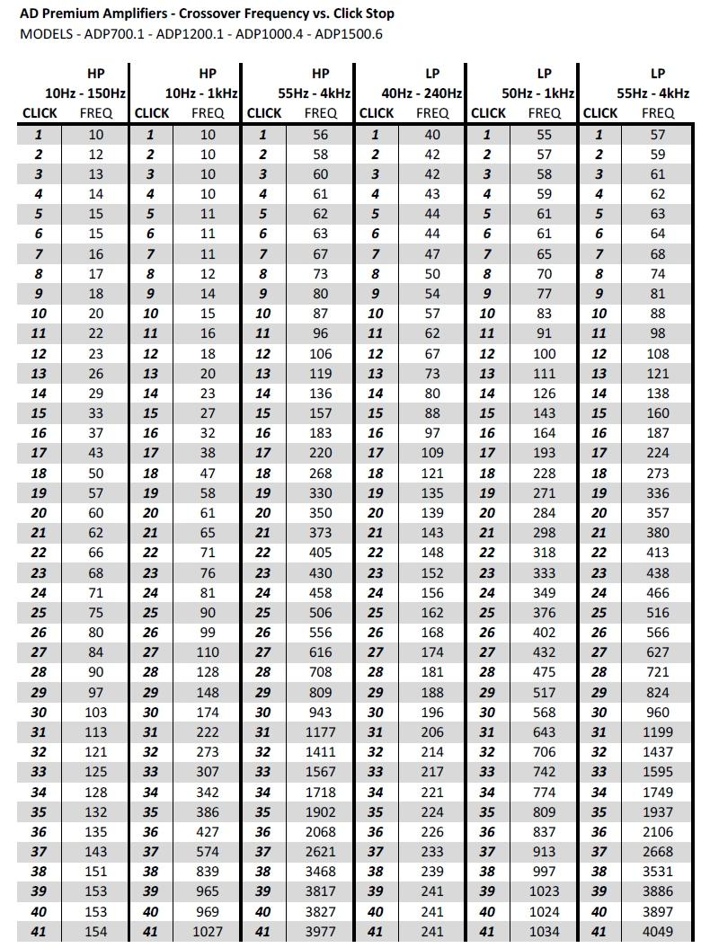
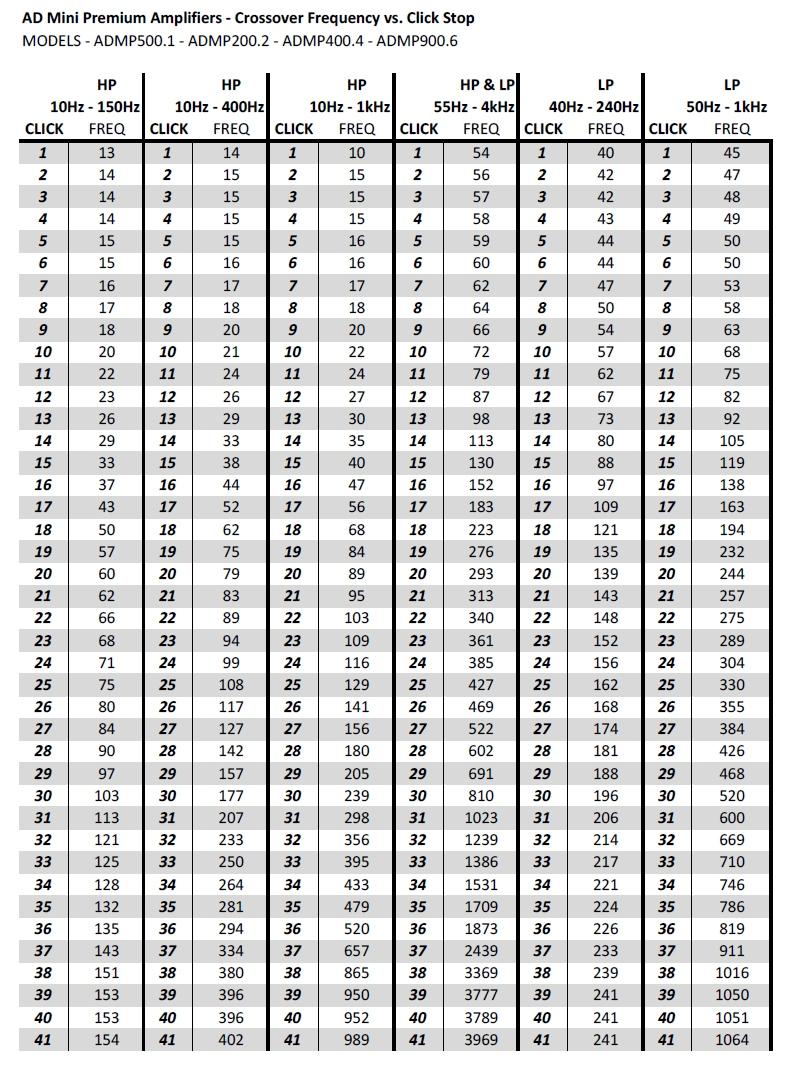
2 INDEX Technology Pages 1, ADP Specifications Page 3 ADMP Specifications Page 4 ADP and ADP100.1 Pages 5, 6, 7 ADP Pages 8, 9, 10 ADP Pages 11, 1, 13, 14 ADMP Page 15 ADMP 00. Pages 16 ADMP Pages 17, 18, 19 ADMP Pages 0, 1, ADP FREQUENCY CHART Page 3 ADMP FREQUENCY CHART Page 4 FUSE RATINGS and WIRE GAUGE CHART Page 5 BALANCED-UNBALANCED CONVERSIONS Page 6-30 INFORMATION Page 31
3 Technology Page 1 AD DESIGNS is proud to introduce these new amplifiers to the market. They employ state of the art electronics with class leading technology. The ADP series employ fully regulated power supplies which deliver constant output voltage independent of the vehicle s battery voltage. Should the vehicle s battery voltage drop below about 11.5 volts, the amplifiers will simply loosen up their regulated status and only continuous output power would reduce slightly. The output power with music shall remain essentially the same. ADP amplifiers employ 4dB/octave Linkwitz-Riley crossovers for both High and Low pass types and ultra low noise integrated circuits are used throughout the front end stages. The ADMP series employ quasi regulated power supplies which are dependent on the value of the vehicle s battery voltage. ADMP amplifiers employ 1dB/octave Linkwitz-Riley crossovers for both High and Low pass types except the ADMP which has 4dB/octave Linkwitz- Riley crossovers and ultra low noise integrated circuits are used throughout the front end stages. All AD DESIGNS amplifiers have the following features unless noted: * Balanced or unbalanced inputs, switchable by either PCB DIP switch or front panel switch depending on model type. * Auto turn on via DC voltage sense on inputs when in BALANCED mode only. Damage will de done to head units with BTL outputs if connected to an UNBALANCED input. * If the hard wired remote turn on feature is used, the auto turn is automatically disabled. * All the amplifiers feature APEC circuitry which prevents clipping and distortion. The current consumption (and heat) are vastly reduced when APEC is activated. * Each amplifier (except ADMP 900.6) feature peak power LEDs on both front panel and the remote. The remote s LED turns from GREEN to RED when peak power is reached. * The amplifiers are protected against over voltage of the battery supply (16.3v shut down), reverse polarity of the battery connections, thermal shut down should the heat sink temperature reach 75 deg C (167 def F), DC protect should and DC in excess of about plus or minus 5 volts appear on any speaker output and short circuit protection on the speaker outputs. (AD does not recommend deliberately shorting the speaker leads or shorting speaker leads from one
4 Page Channel to the other. * All high value electrolytic capacitors used are low ESR 105 deg C types and these have been chosen for their sonic qualities. * Since every class D amplifier employs a reconstruction filter at it s output, the quality of the inductor and capacitor are critical for good sound quality. Wima high pulse current type are used on every amplifier s filter and low loss powdered iron or gapped ferrite cores are used for the inductors. * The class D amplifiers on every model use ultra low gate charge MOSFETs which are critical for the operation of these full range class D amplifiers. Even the mono blocks use the same full range designs! * Power supplies are all over built in terms of transformer size and the quality of the MOSFETs used as well as their unique drive circuits. The size of the transformer and operating frequency of the switch mode power supply determine the ultimate amount of energy which can be extracted. Typical supplies use a switching frequency of between 5 to 40KHz. We use 75KHz which means that we can extract between 1.5 to. times the power from a given transformer core. The MOSFETs we use are also low gate charge high current types. Even though the manufacturer of the MOSFETs rate them at 98 amps each, the physical facts rule. The leads of the MOSFET are not capable of carrying anywhere close to 98 amps! We limit the peak current of any power supply MOSFET to about 30 amps. * The control circuits which are activated in the boot up procedure of the amplifiers are optically isolated from the audio circuits. * Every AD DESIGNS amplifier uses 4 layer FR4 PCB material. Why? Several reasons. Multiple ground planes are employed as we have four available layers to use and these ground planes allow us to drastically lower the radiated EMI of these amplifiers. The routing of critical PCB tracks is enhanced as we have the extra two layers to use. * The full range class D amplifier sections all operate at about 370KHz which is in the sweet spot of efficiency versus radiated EMI versus sound quality. * The amplifiers which have more than one channel have their class D clocks locked at a single frequency which eliminates the beat frequencies we often encounter in most multi channel class D amplifiers out there. * Great attention has been paid to the layout of the PCBs due to the fact that in high frequency switching circuits, PCB layout is as critical as the electronic design itself. * ADP 700.1/100.1 may be bridged with a 4 ohm load to deliver 0w and 400w respectively OR may be cascaded with each subsequent amplifier driving it s own woofer where the master s controls affect all further cascaded amplifiers.
5 Specifications for ADP Amplifiers Page 3 Specification ADP700.1 ADP100.1 ADP ADP ohm 500 watts 800 watts 170w x 4 170w x 6 ohm 700 watts 100 watts 50w x 4 50w x 6 Compared Continuous Power With APEC fully engaged on Subwoofers 1500 watts 500 watts 1000w x 1000w x 3 Input Sensitivity (Unbalanced) v to 8v Input Sensitivity (Balanced) v to 16v Input Impedance at 1KHz Input Impedance at 1KHz K ohm balanced per leg K ohm unbalanced Frequency Response Hz to 35KHz -1dB KHz 4 ohm <0.5% <0.5% <0.1% <0.1% Noise below rated output A weighted -96dB -98dB -94dB -94dB All crossovers are 4dB/octave Linkwitz-Riley High Pass Crossover Hz-150Hz----- N/A N/A High Pass Crossover Ch 1 N/A N/A 55Hz-4KHz 55Hz-4KHz High Pass Crossover Ch 34 N/A N/A 10Hz-1KHz 55Hz-4KHz High Pass Crossover Ch 56 N/A N/A N/A 10Hz-1KHz Low Pass Crossover Hz-30Hz----- N/A N/A Low Pass Crossover Ch 1 N/A N/A 55Hz-4KHz N/A Low Pass Crossover Ch 34 N/A N/A 55Hz-4KHz 55Hz-4KHz Low Pass Crossover Ch 56 N/A N/A N/A 50Hz-1KHz Remote Level Port Yes Yes Yes Yes Fuse Rating with 4 ohm 30A 40A 5A** 40A** Fuse Rating with ohm 60A 80A 50A** 60A** ** These fuse ratings should be lowered if channels are run in High Pass mode due to the fact that the energy contact is substantially reduced (thus current draw) when channels are in mode. A 30% reduction is a good number. Size (3 x 51.4mm) 50.5mm 347.7mm 50.5mm 347.7mm Size (9.13 x.0 ) Net Weight (Kg)
6 Specifications for ADMP Amplifiers Page 4 Specification ADMP500.1 ADMP00. ADMP400.4 ADP ohm watts 100w x 80w x 4 80w x 4 00w x ohm 500 watts 15w x 110w x 4 110w x 4 80w x Compared Continuous Power with APEC fully engaged on subwoofers 1000w 500w x 1 500w x 500w x 1000w x 1 Input Sensitivity (Unbalanced) v to 8v Input Sensitivity (Balanced) v to 16v Input Impedance at 1KHz Input Impedance at 1KHz Frequency Response K ohm balanced per leg K ohm unbalanced Hz to 35KHz -1dB KHz 4 ohm <01% <0.1% <0.1% <0.1% Noise below rated output A weighted -95dB -89dB -89dB -89dB -93dB ADMP500.1 has 4dB/octave crossovers, all others 1dB/octave, all Linkwitz-Riley High Pass Crossover 10Hz-150Hz N/A N/A N/A High Pass Crossover Ch 1 N/A 10Hz-400Hz 55Hz-4KHz 55Hz-4KHz High Pass Crossover Ch 34 N/A N/A 10Hz-1KHz 10Hz-1KHz High Pass Crossover Ch 56 N/A N/A N/A 10Hz-1KHz Low Pass Crossover 40Hz-40Hz N/A N/A N/A Low Pass Crossover Ch 1 N/A 55Hz-4KHz N/A N/A Low Pass Crossover Ch 34 N/A N/A 55Hz-4KHz 55Hz-4KHz Low Pass Crossover Ch 56 N/A N/A N/A 50Hz-1KHz Remote Level Port Yes Yes Yes Yes Fuse Rating with 4 ohm 30A 15A** 0A** 5A** Fuse Rating with ohm 50A 5A** 30A** 40A** ** These fuse ratings should be lowered if channels are run in High Pass mode due to the fact that the energy contact is substantially reduced (thus current draw) when channels are in mode. A 30% reduction is a good number. Size (151 x 49.9mm) 09.mm 09.mm 09.mm 340.8mm Size (5.94 x 1.96 ) Net Weight (Kg) Net Weight (lbs)
7 ADP and ADP Single amplifier driving one or two woofers Page 5 1) Set BAL/UNBAL switch to suit the source. DO NOT set to unbalanced if using a head unit which has BTL outputs. ) Set High and Low Pass crossovers to suit the woofer 3) Set the X OVER switch to for the Low Pass crossover to be bypassed. This function is used for systems with DSP. 4) Set the X OVER switch to /BP so that the Low Pass crossover is active 5) Set the control to suit the signal source s output level. 6) The easiest way to set the control is to set the volume control of the signal source to about -90% of it s maximum and then whilst playing your favourite CD, set the control until the APEC LED just flashes on the loudest peaks. 7) Set the switch to master. 8) If the remote level controller is used, set the control close to fully CW. 9) Connect the woofer(s) to the speaker outputs making sure that the MINIMUM speaker impedance is ohms. PWR APEC PRT SLAVE MASTER 8v 0.5v /BP UNBAL BAL 1 REMOTE X OVER LINE OUT Active controls & switch positions are shown in RED 10-40Hz LINE IN To amplifier s inputs HU Outputs CD 1 REMOTE OUT GND REM BATT SPEAKER IMPEDANCE OHM MINIMUM ADP SEE SPEC PAGE 100A
8 ADP and ADP Two amplifiers D driving one or two woofers Page 6 1) Set the switch to master for the MASTER and to SLAVE for the SLAVE. ) If the remote level controller is used, set the control close to fully CW on the MASTER amplifier. The remote port on the slave is not active. 3) Connect the - line out of the master to the #1 line input of the slave. 4) Connect the woofer(s) as shown making sure that the MINIMUM speaker impedance is 4 ohms. 5) None of the controls on the SLAVE are active Hz PWR APEC PRT SLAVE MASTER 8v 0.5v /BP UNBAL BAL 1 REMOTE X OVER LINE OUT LINE IN HU Outputs To amplifier s inputs Active controls & switch positions are shown in RED are shown in RED CD 1 REMOTE OUT PWR APEC PRT REMOTE LINE OUT SLAVE MASTER 8v 0.5v /BP X OVER UNBAL BAL LINE IN 1 TO REMOTE INPUTS OF BOTH S GND REM BATT SPEAKER IMPEDANCE OHM MINIMUM SEE SPEC PAGE 100A #10 WIRE AS SHOWN 100% IMPORTANT GND REM BATT ADP OHM MINIMUM SPEAKER IMPEDANCE OHM MINIMUM ADP 100.1
9 ADP and ADP Two amplifiers IN CASCADE driving individual woofers Page 7 1) Set the switch to master for the MASTER and to SLAVE for the SLAVE. ) If the remote level controller is used, set the control close to fully CW on the MASTER amplifier. The remote port on the slave is not active. 3) Connect the line out of the master to the #1 line input of the slave. 4) Connect the woofers as shown making sure that the MINIMUM speaker impedance is 4 ohms. 5) None of the controls on the SLAVE are active Hz PWR APEC PRT SLAVE MASTER 8v 0.5v /BP UNBAL BAL 1 REMOTE X OVER LINE OUT Active controls & switch positions are shown in RED HU Outputs CD 1 LINE IN To amplifier s inputs REMOTE OUT PWR APEC PRT REMOTE LINE OUT SLAVE MASTER 8v 0.5v /BP X OVER UNBAL BAL LINE IN 1 TO REMOTE INPUTS OF BOTH S GND REM BATT SPEAKER IMPEDANCE OHM MINIMUM ADP OHM MINIMUM SEE SPEC PAGE 100A GND REM BATT OHM MINIMUM SPEAKER IMPEDANCE OHM MINIMUM ADP 100.1
10 ADP Page 8 1) Set BAL/UNBAL switch to suit the source. DO NOT set to unbalanced if using a head unit which has BTL outputs. Please refer to Page 6 for details on how to do this. ) Channels 1 have four modes of operation. Full range: Set the X OVER switch to FR and all crossovers are bypassed. High Pass: Set the X OVER switch to and the High Pass crossover is active. Low Pass: Set the X OVER switch to and the switch to and the Low Pass crossover is active Band Pass: Set the X OVER switch to and the switch to BP and both Highand Low Pass crossovers are active. 3) Channels 34 have four modes of operation Full range: Set the X OVER switch to and set the High Pass crossover to 10Hz. High Pass: This is a variation of above where the High Pass crossover is set to a frequency much greater than 10Hz. Low Pass: Set the X OVER switch to /BP and both High and Low Pass crossovers are active. For Low Pass the High Pass is set to 10Hz Bandpass the High pass is typically set higher than 10Hz. 4) The FUNCTION switch when set to MONO mixes the signals of channels 34 to mono, feeds these to the main amplifiers and allows the use of the remote port. This is typically used when the is used as a three channel amplifier with channels 34 running subs and channels 1 running component speakers. 5) The switch labeled INPUT allows the use of a two channel source to drive all four channels. The signal source must be connected to inputs 34. Some examples of systems using ADP with and without ADP700.1/100.1 ADP in High Pass driving four component speakers To amplifier s inputs APEC PRT PWR 1/ 3/4 REMOTE 8v 0.5v FR X OVER MONO ST CH K CH BP /BP K INPUT USE INPUTS CD 1 HU Outputs v 0.5v 55 4K 10 1K FUNCTION X OVER 4 REMOTE OUT Active controls & switch positions are shown in RED GND REM BATT SPEAKER IMPEDANCE OHM MINIMUM/CHANNEL OR 4 OHM/D PAIR ADP SEE SPEC PAGE 100A ADP700.1 or may be added for sub woofer duty
11 ADP Page 9 ADP in tri channel driving component speakers off channels 1 and sub woofer(s) off channels 34 either separate woofers or in bridged mode as shown below Active controls & switch positions are shown in RED To amplifier s inputs APEC PRT PWR 1/ 3/4 REMOTE 8v 0.5v FR X OVER MONO ST CH K CH BP /BP K 4 INPUT USE INPUTS CD 1 HU Outputs 8v 0.5v 55 4K 10 FUNCTION X OVER K 4 REMOTE OUT THE FUNCTION SWITCH MAY BE SET TO MONO or ST DEPENDING ON THE REQUIREMENT OF THE REMOTE PORT Hz 10-40Hz GND REM BATT SPEAKER IMPEDANCE OHM MINIMUM/CHANNEL OR 4 OHM/D PAIR SEE SPEC PAGE ADP A Minimum impedance in bridge mode is 4 ohm Alternatively two separate woofers may be connected to ch s 34 with a minimum impedance of ohms EACH
12 ADP Page 10 ADP driving two tweeters from Ch 1 and Midrange from Ch 34 With an ADP700.1 or driving sub woofer speakers and a subwoofer Active controls & switch positions are shown in RED 4KHz To amplifier s inputs APEC REMOTE FR CH BP HU Outputs PRT PWR 1/ 3/4 8v 0.5v X OVER MONO ST 55 4K CH /BP 55 4K 5 50 INPUT USE INPUTS 34 CD v 0.5v 55 4K 10 1K FUNCTION X OVER 4 REMOTE OUT 4KHz TWEETERS GND REM BATT SPEAKER IMPEDANCE OHM MINIMUM/CHANNEL OR 4 OHM/D PAIR ADP MIDRANGE SEE SPEC PAGE 100A PWR APEC PRT SLAVE MASTER 8v 0.5v /BP BAL UNBAL 1 REMOTE X OVER LINE OUT LINE IN 10-40Hz SEE SPEC PAGE GND REM BATT SPEAKER IMPEDANCE OHM MINIMUM ADP 100.1
13 ADP Page 11 1) Set BAL/UNBAL switch to suit the source. DO NOT set to unbalanced if using a head unit which has BTL outputs. Please refer to Page 7 for details on how to do this. ) Channels 1 have two modes of operation. Full range: Set the X OVER switch to FR and the crossover is bypassed. High Pass: Set the X OVER switch to and the High Pass crossover is active. 3) Channels 34 have five modes of operation. Full range: Set the X OVER switch to FR and all crossovers are bypassed.. High Pass: Set the X OVER switch to and the High Pass crossover is active Low Pass: Set the X OVER switch to and the Low Pass crossover is active Band Pass: Set the X OVER switch to and the switch to BP and both High and Low Pass crossovers are active. Copy 5/6: Set the switch to COPY 5/6. In this mode, the signals from Ch 56 are fed into the Low Pass crossover of Ch 34. Whatever settings are done for Ch 56 WILL be duplicated by Ch 34 BUT the Low Pass crossover of Ch 34 is still in circuit. This mode of operation is intended to allow Ch 34 to duplicate Ch 56 when Ch 56 are set in Low Pass mode driving sub woofers. The Low Pass crossover of Ch 3_4 is then set to 4KHz to remove it from the passband set by the crossover sof Ch 56. 4) Channels 56 have four modes of operation Full range: Set the X OVER switch to FR and all crossovers are bypassed.. High Pass: Set the X OVER switch to and the High Pass crossover is active Low Pass: Set the X OVER switch to and the Low Pass crossover is active Band Pass: Set the X OVER switch to and the switch to BP and both High and Low Pass crossovers are active. 5) The FUNCTION switch when set to MONO mixes the signals of channels 56 to mono, feeds these to the main amplifiers and allows the use of the remote port. This is typically used when the is used where Ch 56 are running sub woofers. 6) The switch labeled INPUT SELECT allows the use of a two, four or six channel source. In position 6 the amplifier is a six in, six out configuration. In position 4 the amplifier is a 4 in, 6 out configuration. Ch 1-4 feed their respective outputs and Ch 56 receive a mixed mono signal from Ch 13 and 4 respectively. In position the amplifier is a in, 6 out configuration. Ch 1 input feeds Ch 3 and 5 and Ch input feeds Ch 4 and 6. Typical modes of operation of the ADP A) All channels in FR mode and an outboard DSP processor is used. B) Ch 1 and 34 set to mode driving four component speakers with Ch 56 driving subs. C) Ch 1 set to mode driving two component speakers and Ch 3-6 driving subs (See copy 5/6 above. D) Ch 1 in mode driving tweeters, Ch 34 in BP mode driving midrange and Ch 56 driving subs.
14 ADP Page 1 System One Ch 1 and 34 set to mode driving four component speakers with Ch 56 driving subs. PWR PRT APEC / 3/4 55 4K 8v 0.5v 55 4K 55 4K 8v 0.5v 5/6 X OVER X OVER INPUT SELECT 8v 0.5v FR X OVER CH 1 CH 34 COPY FR 5/6 BP CH 56 FR 700 BP 15 1K 10 Active controls & switch positions are shown in RED K 10-40Hz 4 6 MN ST FUNCTION THE FUNCTION SWITCH MAY BE SET TO MN or ST DEPENDING ON THE REQUIREMENT OF THE REMOTE PORT 5 6 To amplifier s inputs HU Outputs CD 1 REMOTE OUT IF ONLY TWO INPUTS ARE USED THEN SET THE INPUT SELECT TO MINIMUM IMPEDANCE IS 4 OHMS IN GND REM BATT SPEAKER IMPEDANCE OHM MINIMUM/CHANNEL OR 4 OHM/D PAIR ADP THE SUB WOOFER IS SHOWN CONNECTED D CH 56 TWO SUBS MAY OF COURSE BE CONNECTED EACH TO Ch 5 AND Ch 6 MINIMUM IMPEDANCE PER WOOFER IS OHM SEE SPEC PAGE 100A
15 ADP Page 13 System Two Channels 1 set to mode driving two component speakers and channels 3-6 driving either two woofers in bridge mode (as shown) or four woofers, one on each of channels 3, 4, 5 and 6. PWR PRT APEC / 3/4 55 4K 8v 0.5v 55 4K 55 4K 8v 0.5v 5/6 X OVER X OVER INPUT SELECT 8v 0.5v CH 1 CH 34 COPY FR 5/6 BP FR X OVER CH 56 FR 700 BP 15 1K 10 4KHz Active controls & switch positions are shown in RED K 10-40Hz 4 6 MN ST FUNCTION THE FUNCTION SWITCH MAY BE SET TO MN or ST DEPENDING ON THE REQUIREMENT OF THE REMOTE PORT 5 6 To amplifier s inputs HU Outputs CD 1 REMOTE OUT IF ONLY TWO INPUTS ARE USED THEN SET THE INPUT SELECT TO MINIMUM IMPEDANCE IS 4 OHMS IN GND REM BATT SPEAKER IMPEDANCE OHM MINIMUM/CHANNEL OR 4 OHM/D PAIR ADP THE SUB WOOFERS ARE SHOWN CONNECTED D. FOUR SUBS MAY OF COURSE BE CONNECTED EACH TO Ch 3,4,5 & 6 MINIMUM IMPEDANCE PER WOOFER IS OHM SEE SPEC PAGE 100A
16 ADP Page 14 System Three Channels 1 set to mode driving tweeters. Channels 34 in BP mode driving midrange. Channels 55 in mode driving woofers. PWR PRT 4KHz APEC / 3/4 55 4K 8v 0.5v 55 4K 55 4K 8v 0.5v 5/6 X OVER X OVER INPUT SELECT 8v 0.5v FR X OVER CH 1 CH 34 COPY FR 5/6 BP CH 56 FR 700 BP 15 1K 10 4KHz Active controls & switch positions are shown in RED K 10-40Hz 4 6 MN ST FUNCTION THE FUNCTION SWITCH MAY BE SET TO MN or ST DEPENDING ON THE REQUIREMENT OF THE REMOTE PORT 5 6 To amplifier s inputs HU Outputs CD 1 REMOTE OUT MINIMUM IMPEDANCE IS 4 OHMS IN GND REM BATT SPEAKER IMPEDANCE OHM MINIMUM/CHANNEL OR 4 OHM/D PAIR ADP THE SUB WOOFER IS SHOWN CONNECTED D CH 56 TWO SUBS MAY OF COURSE BE CONNECTED EACH TO Ch 5 AND Ch 6 MINIMUM IMPEDANCE PER WOOFER IS OHM SEE SPEC PAGE 100A
17 ADMP Single amplifier driving one or two woofers Page 15 1) Set BAL/UNBAL switch to suit the source. DO NOT set to unbalanced if using a head unit which has BTL outputs. ) Set High and Low Pass crossovers to suit the woofer 3) Set the X OVER switch to for the Low Pass crossover to be bypassed. This function is used for systems with DSP. 4) Set the X OVER switch to /BP so that the Low Pass crossover is active 5) Set the control to suit the signal source s output level. 6) The easiest way to set the control is to set the volume control of the signal source to about 86-90% of it s maximum and then whilst playing your favourite CD, set the control until the APEC LED just flashes on the loudest peaks. 7) Set the switch to master. 8) If the remote level controller is used, set the control close to fully CW. 9) Connect the woofer(s) to the speaker outputs making sure that the MINIMUM speaker impedance is ohms Hz REMOTE APEC PROT 8v /BP 0.5v INPUTS UNBALANCED BALANCED PWR ADMP INPUTS Active controls & switch positions are shown in RED To amplifier s inputs HU Outputs CD 1 REMOTE OUT BATT REM GND OHM MINIMUM 50A SEE SPEC PAGE
18 ADMP 00. Page 16 1) Set BAL/UNBAL switch to suit the source. DO NOT set to unbalanced if using a head unit which has BTL outputs. Please refer to page 8 on how to do this. The amplifier has four modes of operation. A) Set the switch to, set the multiplier switch to x1, set the crossover to 10Hz and the amplifier runs effectively in full range. B) Set the switch to, set the crossover to a higher frequency setting, set the multiplier switch in or out depending on the high pass crossover frequency desired and the amplifier runs in High Pass mode. C) Set the X OVER switch to /BP so that the Low Pass crossover is active as well. Setting the crossover to 10Hz allows the amplifier to run in Low Pass. Setting the crossover between 10-40Hz introduces a sub sonic filter. Setting the FUNCTION switch to MN mixes the two channels to mono and allows the REMOTE port to function. D) Setting the and crossovers to suitable frequencies allows the amplifier to operate in bandpass mode to drive midrange drivers in a multiway system. 5) Set the control to suit the signal source s output level. 6) The easiest way to set the control is to set the volume control of the signal source to about 86-90% of it s maximum and then whilst playing your favourite CD, set the control until the APEC LED just flashes on the loudest peaks. 7) Set the switch to master. 8) If the remote level controller is used, set the control close to fully CW. The diagram below shows the ADMP00. connected for sub woofer operation. Active controls & switch positions are shown in RED To amplifier s inputs 10-40Hz REMOTE MN ST /BP HU Outputs 8v 0.5v 55 4K FUNCTION OUT = x1 IN = x10 CD 1 PROT APEC PWR ADMP 00. REMOTE OUT ONE WOOFER PER CHANNEL MAY BE USED INSTEAD OF A SINGLE D DRIVER CH 1 CH BATT REM GND OHM MINIMUM PER CHANNEL OR 4 OHM D MINIMUM SPEAKER IMPEDANCE IS 4 OHM 50A SEE SPEC PAGE
19 ADMP Page 17 1) Set BAL/UNBAL switch to suit the source. DO NOT set to unbalanced if using a head unit which has BTL outputs. Please refer to page 9 on how to do this. Channels 1 have three modes of operation. A) Set the switch to FR and these channels run in full range with the control being active. B) Set the switch to and these channels run in High Pass mode. C) Set the switch to COPY 34 and channels 1 will follow all settings of channels 34 except that the two controls will be independent. Channels 34 have four modes of operation. A) Set the switch to and set the frequency to 10Hz. The channels now run effectively in full range. B) Setting the crossover to a frequency higher than 10Hz allows these channels to operate in High Pass mode. C) Set the switch to /BP, set the High Pass crossover to 10Hz and set the Low Pass crossover to the desired frequency and these channels operate in Low Pass mode. D) Setting the High Pass crossover to a higher frequency than 10Hz allows these channels to operate in Band Pass mode. E) Setting the FUNCTION switch to MN, mixes the 33 signals to mono and invokes the remote port. ) Set the controls to suit the signal source s output level. 3) The easiest way to set the control is to set the volume control of the signal source to about -90% of it s maximum and then whilst playing your favourite CD, set the control until the APEC LED just flashes on the loudest peaks. 4) If the remote level controller is used, set the control close to fully CW. 5) The ADMP400.4 can be set up as a higher powered two channel amplifier. Set the switch of Ch 1 to COPY 34. Set the crossovers on ch 34 to suit your application and connect the two speakers to the terminals marked on the rear panel. As an example setting ch 34 to allows either high power full range operation with set to 10Hz. Setting the switch to /BP and setting the crossover at between 10Hz-50Hz (Now functions as a subsonic crossover) and the to an appropriate frequency allows the amplifier to drive a pair of sub woofers.
20 ADMP Page 18 The diagram below shows the ADMP400.4 set up to drive four component speakers CD 1 REMOTE OUT HU Outputs To amplifier s inputs CH 34 REMOTE FUNCTION MN ST /BP APEC CH1/ CH3/4 ADMP v 0.5v 55 FR COPY34 8v 0.5v CH K K K Active controls & switch positions are shown in RED POWER BATT REM GND OHM MINIMUM PER CHANNEL OR 4 OHM D PROTECT SEE SPEC PAGE 50A
21 ADMP Page 19 The diagram below shows the ADMP400.4 set up to drive two component speakers And a single sub woofer CD 1 REMOTE OUT HU Outputs To amplifier s inputs CH 34 REMOTE FUNCTION MN ST /BP APEC CH1/ CH3/4 ADMP v 0.5v 55 FR COPY34 8v 0.5v CH K K 10-50Hz K Active controls & switch positions are shown in RED POWER BATT REM GND OHM MINIMUM PER CHANNEL OR 4 OHM D PROTECT SEE SPEC PAGE 50A
22 ADMP Page 0 1) Set BAL/UNBAL switch to suit the source. DO NOT set to unbalanced if using a head unit which has BTL outputs. Please refer to page 30 on how to do this. Channels 1 has two modes of operation. A) Set the PUSH SWITCH out to FR and these channels run in full range with the control being active. B) Set the PUSH SWITCH in to and these channels run in High Pass mode. Channels 34 have four modes of operation. A) Set the PUSH SWITCH out to and set the frequency to 10Hz. The channels now run effectively in full range. B) Setting the crossover to a frequency higher than 10Hz allows these channels to operate in High Pass mode. C) Set the PUSH SWITCH in to /BP, set the High Pass crossover to 10Hz and set the Low Pass crossover to the desired frequency and these channels operate in Low Pass mode. D) Setting the High Pass crossover to a higher frequency than 10Hz allows these channels to operate in Band Pass mode. Channels 56 have four modes of operation. A) Set the SLIDE SWITCH to and set the frequency to 10Hz. The channels now run effectively in full range. B) Setting the crossover to a frequency higher than 10Hz allows these channels to operate in High Pass mode. C) Set the SLIDE SWITCH to /BP, set the High Pass crossover to 10Hz and set the Low Pass crossover to the desired frequency and these channels operate in Low Pass mode. D) Setting the High Pass crossover to a higher frequency than 10Hz allows these channels to operate in Band Pass mode. E) Setting the SLIDE SWITCH to MONO mixes the channels to mono and invokes the REMOTE port. The channels continue to operate in /BP mode. ) Set the controls to suit the signal source s output level. 3) The easiest way to set the control is to set the volume control of the signal source to about -90% of it s maximum and then whilst playing your favourite CD, set the control until the APEC LED just flashes on the loudest peaks. 4) If the remote level controller is used, set the control close to fully CW.
23 ADMP Page 1 The diagram below shows the ADMP900.6 set up with channels 1-4 driving component Speakers and channels 56 driving a pair of sub woofers (with alternate single woofer bridged) CD 1 REMOTE OUT Active controls & switch positions are shown in RED REMOTE MONO /BP v 0.5v CH K 10 8v 0.5v K CH 34 IN-/BP OUT- IN- OUT-FR K v 0.5v CH K 750 4K The 6 amplifier inputs may be fed signal in different modes: A) Head unit has 6 outputs, two of them SUB which would drive 56 inputs. B) Head unit has only 4 outputs, use rear outputs and Y-adapt to feed Ch 34 and 56. C) Use only a stereo pair of outputs and double Y-adapt to feed all 6 inputs ADMP Switch set to MONO invokes the REMOTE port 10-50Hz BATT REM GND PWR PROT OHM MINIMUM/CHANNEL OR 4 OHM/D PAIR SEE SPEC PAGE 100A
24 ADMP Page The diagram below shows the ADMP900.6 set up with Ch 1 driving tweeters, Ch 34 Driving midrange and Ch 56 driving a woofer ( A single woofer in bridge mode) CD 1 REMOTE OUT The 6 amplifier inputs must be Y-adapted twice so that Ch 1, 3 & 5 receive the LEFT input signal and, 4 & 6 the RIGHT input signal. Active controls & switch positions are shown in RED 1.5-4KHz REMOTE CH 34 IN-/BP OUT MONO /BP v 0.5v CH K 10 8v 0.5v K IN- OUT-FR K v 0.5v CH K 750 4K 4 ADMP Switch set to MONO invokes the REMOTE port 10-50Hz 1.5-4KHz BATT REM GND PWR PROT OHM MINIMUM/CHANNEL OR 4 OHM/D PAIR AND 6 NO CONNECTIONS SEE SPEC PAGE 100A IMPORTANT MINIMUM WOOFER IMPEDANCE 4 OHM
25 Page 3
26 Page 4

27 Page 5 FUSE CHART L 4 OHM LOADS OHM LOADS ADP A 60A ADP A 80A ADP A* 50A* ADP A* 60A* ADMP A 50A ADMP00. 15A* 5A* ADMP A* 30A* ADMP A* 40A* * These fuse ratings can be reduced by about 30% when channels of these Amplifiers are run in a High Pass Mode.
28 Page 6 ADP THE IS DELIVERED FROM THE FACTORY WITH THE INPUTS SET TO UNBALANCED. TO CONVERT TO BALANCED INPUTS FOLLOW THESE INSTRUCTIONS 1) REMOVE THE BOTTOM COVER OF THE. ) BEHIND THE RCA SOCKETS IS A SWITCH MARKED SW1 AS SHOWN ABOVE. 3) USING A SMALL SCREWDRIVER MOVE THE 4 SMALL LEVERS OF SWITCH SHOWN IN BLUE ABOVE, TO THE OFF POSITION WHICH IS OPPOSITE TO THE PRINT ON THE SWITCH SHOWING ON. 4) TAKE CARE WHEN MOVING THESE LEVERS AS THEY DO NOT REQUIRE MUCH STRENGTH TO MOVE THEM.
29 Page 7 ADP THE IS DELIVERED FROM THE FACTORY WITH THE INPUTS SET TO UNBALANCED. TO CONVERT TO BALANCED INPUTS FOLLOW THESE INSTRUCTIONS 1) REMOVE THE BOTTOM COVER OF THE. ) BEHIND THE RCA SOCKETS IS A VERTICAL PCB AS SHOWN ABOVE. 3) USING A SMALL SCREWDRIVER MOVE THE 6 SMALL LEVERS OF SWITCH SHOWN IN BLUE ABOVE, TO THE OFF POSITION WHICH IS OPPOSITE TO THE PRINT ON THE SWITCH SHOWING ON. 4) TAKE CARE WHEN MOVING THESE LEVERS AS THEY DO NOT REQUIRE MUCH STRENGTH TO MOVE THEM.
30 Page 8 ADMP 00. THE IS DELIVERED FROM THE FACTORY WITH THE INPUTS SET TO UNBALANCED. TO CONVERT TO BALANCED INPUTS FOLLOW THESE INSTRUCTIONS 1) REMOVE THE BOTTOM COVER OF THE. ) TO THE RIGHT OF THE RCA SOCKETS IS A SWITCH Sw AS SHOWN ABOVE. 3) USING A SMALL SCREWDRIVER MOVE THE SMALL LEVERS OF SWITCH SHOWN IN BLUE ABOVE, TO THE OFF POSITION WHICH IS OPPOSITE TO THE PRINT ON THE SWITCH SHOWING ON. 4) TAKE CARE WHEN MOVING THESE LEVERS AS THEY DO NOT REQUIRE MUCH STRENGTH TO MOVE THEM.
31 Page 9 ADMP THE IS DELIVERED FROM THE FACTORY WITH THE INPUTS SET TO UNBALANCED. TO CONVERT TO BALANCED INPUTS FOLLOW THESE INSTRUCTIONS 1) REMOVE THE BOTTOM COVER OF THE. ) BEHIND THE RCA SOCKETS IS A SWITCH, SW1 AS SHOWN ABOVE. 3) USING A SMALL SCREWDRIVER MOVE THE 4 SMALL LEVERS OF SWITCH SHOWN IN BLUE ABOVE, TO THE OFF POSITION WHICH IS OPPOSITE TO THE PRINT ON THE SWITCH SHOWING ON. 4) TAKE CARE WHEN MOVING THESE LEVERS AS THEY DO NOT REQUIRE MUCH STRENGTH TO MOVE THEM.
32 Page 30 ADMP THE IS DELIVERED FROM THE FACTORY WITH THE INPUTS SET TO UNBALANCED. TO CONVERT TO BALANCED INPUTS FOLLOW THESE INSTRUCTIONS 1) REMOVE THE BOTTOM COVER OF THE. ) BEHIND THE RCA SOCKETS IS A SWITCH, SW1 AS SHOWN ABOVE. 3) USING A SMALL SCREWDRIVER MOVE THE 6 SMALL LEVERS OF SWITCH SHOWN IN BLUE ABOVE, TO THE OFF POSITION WHICH IS OPPOSITE TO THE PRINT ON THE SWITCH SHOWING ON. 4) TAKE CARE WHEN MOVING THESE LEVERS AS THEY DO NOT REQUIRE MUCH STRENGTH TO MOVE THEM.
33 Page 31 Website Address AD DESIGNS 115 maple Street Farmington, MO (573)
GND Chassis ground terminal. The chassis ground cable must be connected very tight on a nearby massive and electric conductive place.
 1 Speaker connection Never connect the speaker cables with the chassis ground. This may destroy your amplifier. Check that your speakers are connected correctly which means plus to plus and minus to minus.
APSM-1300/APSM
 APSM-1300/APSM-1500 1 2 3 4 15 14 6 7 9 8 5 10 11 13 12 APSM-2000 1 2 3 4 15 14 6 7 9 8 5 10 11 13 12 1 Speaker connection Never connect the speaker cables with the chassis ground. This may destroy your
9 db/oct, variable bass boost
 Digital class-d linkable/dual mono block amplifier Dual MOS-FET PWM power supply Stable into 1 ohm load 24 db/oct, variable low pass filter 24 db/oct, variable subsonic filter 9 db/oct, variable bass boost
SOUND QUALITY AMPLIFIER
 Owner s Manual SKv2-800.1D SKv2-1500.1D SKv2-2500.1D SKv2-3500.1D SKv2-4500.1D SKv2-1300.2AB SKv2-85.4AB SKv2-100.4AB SKv2-200.4D SOUND QUALITY AMPLIFIER 1. INTRODUCTION Congratulations and thank you for
Owner s Manual 7000 WATTS RMS WATTS RMS COMPETITION D HIGH CLASS D AMPLIFIER HIGH CLASS D AMPLIFIER MADE IN KOREA
 Owner s Manual COMPETITION 7000.1D 7000 WATTS RMS HIGH CLASS D AMPLIFIER COMPETITION 12000.1D 12000 WATTS RMS HIGH CLASS D AMPLIFIER MADE IN KOREA Manual size : 150 x 210mm 2 Installation If you intend
HIGH PERFORMANCE CAR AMPLIFIER
 NS-1 HIGH PERFORMANCE CAR AMPLIFIER Digital Class-D Linkable Mono Block Amplifier Dual MOS-FET PWM Power Supply 1 Ohm Stable Load 24 db/octave - Variable Low Pass Filter 24 db/octave - Variable Subsonic
DD1-1300S. 500 Watts RMS Watts RMS Watts RMS- 1. Mono-Bloc Digital Power Amplifier
 DD1-1300S Mono-Bloc Digital Power Amplifier 500 Watts RMS- 4 900 Watts RMS- 2 Ultimate Sound, Inc. 1300 Watts RMS- 1 Ultimate Europe AB Ultimate Sound, Inc Ultimate Europe AB 163 University Parkway Flojelbergsgatan
English APSM Power Indicator LED 4. Protection Circuit Indicator LED. 1. RCA Input Jacks 2. Remote Bass Level Control
 English APSM-1150 2 1 3 4 1. RCA Input Jacks 2. Remote Bass Level Control 3. Power Indicator LED 4. Protection Circuit Indicator LED 1 5 4 3 2 1. Speaker Connection 2. Ground 3. Remote Turn-on Input 4.
IA SERIES OWNER'S MANUAL
 IA SERIES OWNER'S MANUAL overview OVERVIEW / CONTACT contact Congratulations and thank you for purchasing an Incriminator Audio amplifier for your new automotive sound system. Like all of Incriminator
PB 700 PB 1000 PB 1100 PB 1500 PB 2600 PB 1200 PB 1700 PB 2200 PB 2700 USER'S MANUAL.
 PB 700 PB 1000 PB 1100 PB 1500 PB 2600 PB 1200 PB 1700 PB 2200 PB 2700 USER'S MANUAL www.pyramidcaraudio.com congratulations... on your purchase of a Pyramid America Series amplifier. This amplifier extends
BRIDGEABLE MOSFET POWER AMPLIFIERS BZA-2290/BZA-2390 BZA-2490/BZA-4190 OWNER'S MANUAL
 BRIDGEABLE MOSFET POWER AMPLIFIERS BZA-2290/BZA-2390 BZA-2490/BZA-4190 OWNER'S MANUAL Table of Contents Table of Contents 1 2 3~7 8 9~11 9 10~11 Troubleshooting 12 Wiring 13 Introduction & Features Introduction
REFERENCE 705s. 5/3 Channel Power Amplifier OWNERS MANUAL AND INSTALLATION GUIDE
 REFERENCE 705s 5/3 Channel Power Amplifier OWNERS MANUAL AND INSTALLATION GUIDE 1 CONGRATULATIONS! You now own the REFERENCE705s Amplifier, the product of an uncompromising design and engineering philosophy.
D-Tower Amplifier Series. Owner s Manual
 D-Tower Amplifier Series Owner s Manual CONGRATULATIONS! You now own a D-Tower Amplifier, the product of an uncompromising design and engineering philosophy. We suggest you take a moment to document the
Stealth Amplifier Series. Owner s Manual
 Stealth Amplifier Series Owner s Manual CONGRATULATIONS! You now own a Stealth Amplifier, the product of an uncompromising design and engineering philosophy. We suggest you take a moment to document the
L1.600D L1.1100D L1.1600D L1.2100D L2.290 L2.400 L4.540 L4.480 L5.850
 L1.600D L1.1100D L1.1600D L1.2100D L2.290 L2.400 L4.540 L4.480 L5.850 CONGRATULATIONS! You now own a Lil Wonder 4 Series Amplifier, the product of an uncompromising design and engineering philosophy. We
This amplifier is designed for low-frequency information only and it is not capable of reproducing any mid/high-frequency information.
 Thank you for purchasing the Lanzar OPTI Class-D amplifier. Rest assured you have purchased a quality product designed and engineered to give you many years of uncompromised musical service. The OPTI Class-D
Owner's manual. ZX-series
 Owner's manual ZX-series Competition Class D, Competition Bass/SPL Amplifier Before operating the unit, please read this manual throughly and retain it for future reference. Protect your Investment Note
O P T I O W N E R ' S M A N U A L
 OPTI OWNER'S MANUAL 1. Contents 2. Introduction 3. Features 4. Specifications 5. Amplifier installation 6. 7. Features and controls 8.9.System wiring 10.11. Troubleshooting OPTI OWNER'S MANUAL - 1 Thank
PLANNING YOUR SYSTEM
 INTRODUCTION HERTIAGE amplifiers provide high-performance sound reinforcement for your mobile audio equipment. Its versatility enables compatibility with optional Equalizers, Frequency Dividing Crossover
************* OWNER'S MANUAL STAX1250/2 STAX1800/2 STAX2200/2 STAX1200/4 STAX1600/4 STAX2300/4 STAX2000/1D STAX4000/1D STAX5500/1D
 ************* OWNER'S MANUAL STAX1250/2 STAX1800/2 STAX2200/2 STAX1200/4 STAX1600/4 STAX2300/4 STAX2000/1D STAX4000/1D STAX5500/1D INTRODUCTION Power Acoustik amplifiers provide high-performance sound
OPTI OWNER'S MANUAL - 1
 1. Contents 2. Introduction 3. Features 4. Specifications 5. Amplifier installation 6. 7. Features and controls 8.9.System wiring 10.11. Troubleshooting OPTI OWNER'S MANUAL - 1 Thank you for purchasing
OWNER'S MANUAL. Super Natural Sound High Performance Technology. SP dbpro
 OWNER'S MANUAL Super Natural Sound High Performance Technology SP-1500.2 dbpro SP-2000.2 dbpro SP-2300.2 dbpro FEATURES [SP-1500.2 dbpro] 2/1 Channel Bridgeable Class A/B Amplifier MOSFET PWM Power Supply
REFERENCE Class A. 4/3/2 Channel Power Amplifier OWNERS MANUAL AND INSTALLATION GUIDE
 REFERENCE Class A PICASSO 4/3/2 Channel Power Amplifier OWNERS MANUAL AND INSTALLATION GUIDE 1 CONGRATULATIONS! You now own the REFERENCE Class A PICASSO Amplifier, the most musical amplifier ever created
Owner's Manual WARNING 65-C5009-MA INTRODUCTION FEATURES
 65-C5009-MA Model No.: SRX-D0504; SRX-D1501; SRX-D2501; SRX-D4001 :A3 INTRODUCTION Amplifiers provide high-performance sound reinforcement for your mobile audio equipment. It s versatility enables compatibility
TA5604 Owner s Manual
 TA5604 Owner s Manual Introduction Thank you for choosing MTX to help reach the ultimate goal with your vehicle. Adding MTX amplifiers and matching MTX speakers and subwoofers with StreetWires connections
TA4252 Owner s Manual
 TA4252 Owner s Manual Introduction Thank you for choosing MTX to help reach the ultimate goal with your vehicle. Adding MTX amplifiers and matching MTX speakers and subwoofers with StreetWires connections
MODEL: Duo Product id:duomk214f Duo OWNER S MANUAL
 MODEL: Product id:duomk214f OWNER S MANUAL Introduction We thank you for purchasing our amplifiers. Your decision to be part of something different is what we strive for. Our products reflects who we are,
TA3202 Owners Manual. Input Sensitivity Switch: 100mV-1V/1V-10V Crossover: Hi, 12dB / Low, 85Hz, Defeatable
 TA3202 Owners Manual Introduction Thank you for choosing MTX to help reach your ultimate goal with your vehicle. Adding MTX amplifiers and matching MTX speakers and subwoofers with StreetWires connections
Full FET Class AB Amplifier
 Full FET Class AB Amplifier INTRODUCTION & FEATURES... 2 FEATURES & CONTROLS... 3-4 specification... 5 installation & precautions... 5 SYSTEM WIRING...6-13 2channel SYSTEM WIRING...6-8 4channel SYSTEM
Some say car audio tuning is an ART! System Setup. Digital Signal Processor
 Some say car audio tuning is an ART! At NXS Mobile Audio we strive to provide some of the latest technology tools that make the quest for the perfect tune so much easier. Our goal was a technologically
Amplifier Manual. Models: MX MX MX Features
 Amplifier Manual Models: MX 800.5 MX 600.4 MX 800.1 Phoenix Gold is excited to introduce the series everyone has been asking for. A sub-compact series of amplifiers engineered for vehicles where space
MODEL: M1u Product id:m1ud13 M1u OWNER S MANUAL
 MODEL: Product id:m1ud13 OWNER S MANUAL Foreword We congratulate you with your decision to purchase our reveered niche amplifiers. Every product developed by implements the keystones of our company philosophy;
Owner s & Installation manual
 Owner s & Installation manual 6 CHANNEL AMPLIFIER English Thank you for purchasing this Clarion product. Please read the owner s manual in its entirety before operating the equipment. After reading this
EVOLUTION OF POWER AMPLIFIERS M / M M / M / M M1500.1D / M2500.1D / M4000.1D
 R EVOLUTION OF AMPLIFIERS M16. / M3. M1. / M1. / M. M15.1D / M5.1D / M.1D GENERAL INSTALLATION PROCEDURE System Design The success of any car stereo system relies on several factors, such as the system
Owner's Manual WARNING 65-C5010-MA INTRODUCTION FEATURES
 65-C5010-MA Model No.: SRQ-D0504; SRQ-D1501; SRQ-D2501; SRQ-D4001 :A5 INTRODUCTION Amplifiers provide high-performance sound reinforcement for your mobile audio equipment. It s versatility enables compatibility
D Artagnan5.1 Theater Amplifier
 D Artagnan5.1 Theater Amplifier Owner s Manual and Installation Guide Congratulations! You now own the Soundstream D Artagnan5.1 amplifier, the product of an uncompromising design and engineering philosophy.
Congratulations on your purchase of a Lanzar EVOLUTION amplifier. You have purchased a quality product designed
 Congratulations on your purchase of a Lanzar EVOLUTION amplifier. You have purchased a quality product designed and engineered to give you many years of uncompromised musical service. EVOLUTION amplifiers
F O R T H E L O V E O F M U S I C LP100 OWNER'S MANUAL AND INSTALLATION GUIDE INTRODUCTION
 F O R T H E L O V E O F M U S I C LP100 OWNER'S MANUAL AND INSTALLATION GUIDE INTRODUCTION You have purchased an amplifier that leads the way with sound quality, reliability, and features. These high performance
REFERENCE /3 Channel Power Amplifier OWNERS MANUAL AND INSTALLATION GUIDE
 REFERENCE 705 5/3 Channel Power Amplifier OWNERS MANUAL AND INSTALLATION GUIDE 1 CONGRATULATIONS! You now own the REFERENCE705 Amplifier, the product of an uncompromising design and engineering philosophy.
Amplifier Manual. Models: RX RX Features
 Amplifier Manual Models: RX2 750.5 RX2 400.4 The RX2-series amplifiers are the next evolution of the reliable and great sounding RX series. With a new, more efficient circuit design, we have increased
USER MANUAL LIMITED WARRANTY AMPLIFIERS WDX300.4 : WDX400.4 : WDX800.4 WDX1K : WDX2K : WDX3K : WDX5K. Installation Instructions Owners Manual
 LIMITED WARRANTY DB Drive warrants any products purchased in the U.S.A. from an authorized DB Drive dealer. All products are warranted to be free from defects in material and workmanship under normal use
MANUAL AQA430SL AQA430WT MODELS: '~.,t::r's
 ) '~.,t::r's MANUAL MODELS: AQA430SL AQA430WT INTRODUCTION Our Amplifiers provide high-performance sound reinforcement for your mobile audio equipment. Its versatility enables compatibility with optional
Owner s manual & Installation manual Mode d emploi et manuel d installation Manual de instrucciones y de instalación XC6210 XC6410
 Owner s manual & Installation manual Mode d emploi et manuel d installation Manual de instrucciones y de instalación XC6210 XC6410 XC AMPLIFIERS AMPLIFICATEURS XC AMPLIFICADORES XC INTRODUCTION The Clarion
Passive Crossovers MADE EASY. Pre-made Crossovers. Mobile Audio Interfacing Equipment $9.95
 Premade Crossovers $9.95 Competition and super deluxe systems are nice to do. This is particularly true when a lot of special crossovers are designed with different ohm loads in the various frequency sections.
GENESIS A U T O M O T I V E A U D I O P H I L E P R O D U C T S H A N D M A D E I N E N G L A N D
 GENESIS A U T O M O T I V E A U D I O P H I L E P R O D U C T S GENESIS W h a t m a k e s o u r a m p l i f i e r s s o s p e c i a l? GENESIS amplifiers have been perfected over 25 years which has made
INTRODUCTION FEATURES SPECIFICATIONS. Built-in Crossover
 INTRODUCTION Congratulations on your purchase of a LEGACY ICON Car Amplifier. The unit is the result of an extensive engineering project to create the finest automotive high fidelity product available.
TA7402 Owner s Manual
 TA7402 Owner s Manual Introduction Thank you for choosing MTX to help reach the ultimate goal with your vehicle. Adding MTX amplifiers and matching MTX speakers and subwoofers with StreetWires connections
360mm (14-3/16 ) x 224mm (8-13/16 ) x 67mm (2-5/8 )
 x 224mm (8-13/16 ) x 67mm (2-5/8 )") EN-41400 (4 Channel) EN-21200 (2 Channel) Class Class-AB Class-AB Power 1400 Watts 1200 Watts Frequency Response 10Hz - 42kHz 10Hz - 45kHz Dimensions 360mm (14-3/16 ) x 224mm (8-13/16 ) x 67mm (2-5/8 )
EN-41400 (4 Channel) EN-21200 (2 Channel) Class Class-AB Class-AB Power 1400 Watts 1200 Watts Frequency Response 10Hz - 42kHz 10Hz - 45kHz Dimensions 360mm (14-3/16 ) x 224mm (8-13/16 ) x 67mm (2-5/8 )
AMPLIFIERS BI BI BI BI4400.4
 LIMITED WARRANTY Bass Inferno warrants any products purchased in the U.S.A. from an authorized Bass Inferno dealer. All products are warranted to be free from defects in material and workmanship under
Quota OWNER S MANUAL
 MODEL: MKII Product id:quotad12 OWNER S MANUAL Foreword We congratulate you with your decision to purchase our reveered niche amplifiers. Every product developed by implements the keystones of our company
Bel Canto Design evo Digital Power Processing Amplifier
 Bel Canto Design evo Digital Power Processing Amplifier Introduction Analog audio power amplifiers rely on balancing the inherent linearity of a device or circuit architecture with factors related to efficiency,
JAD SERIES OWNER S MANUAL. JAD Channel Full Range Class D Amplifier
 JAD SERIES OWNER S MANUAL JAD900.5 5 Channel Full Range Class D Amplifier Authorized Dealer Name: Purchase Date: Model Number: Serial Number: JAD900.5 PERFORMANCE MODEL: RMS Power (4 Ohms, Stereo) RMS
TA5601 Owner s Manual
 TA5601 Owner s Manual Introduction Thank you for choosing MTX to help reach the ultimate goal with your vehicle. Adding MTX amplifiers and matching MTX speakers and subwoofers with StreetWires connections
LK 705. Troubleshooting -12-
 Troubleshooting Before removing your amplifier, refer to the list below and follow the suggested procedures. Always test the speakers and their wires first. No Output Only one channel works Confirm that
CONGRATULATIONS TABLE OF CONTENTS
 model 500/2 CONGRATULATIONS Congratulations for choosing a Directed Audio power amplifier from Directed Electronics, the industry leader in high quality automotive security and audio equipment since 1990.
MS-AM402. User/Installation Manual FUSIONENTERTAINMENT.COM
 MS-AM MARINE AMPLIFIER User/Installation Manual FUSIONENTERTAINMENT.COM Contents Feature Overview...Pg 3 Control Descriptions.................................Pg Installation.........................................Pg
A400HLX A600HLX. Installation Assistance. Amplifier Installation and Operation
 3 5 60 125 60 125 2 4 0dB 0dB 12dB 12dB 3 5 60 125 60 125 2 4 8V 8V.3V.3V MODE Amplifier Installation and Operation A400HLX A600HLX 400 MOSFET Power Supply 4 channel bridgeable BASS L-CHX R-CHX LEVEL POWER
F O R T H E L O V E O F M U S I C SERIES 218 DPS200 OWNER'S MANUAL AND INSTALLATION GUIDE INTRODUCTION
 F O R T H E L O V E O F M U S I C SERIES 218 DPS200 OWNER'S MANUAL AND INSTALLATION GUIDE INTRODUCTION You have purchased an amplifier that leads the way with sound quality, reliability, and features.
HT Watt 6 Channel Class D amplifier OWNER S MANUAL
 HT-6 900 Watt 6 Channel Class D amplifier OWNER S MANUAL Congratulations! Thank you for purchasing the Wet Sounds Hydro-Tech TM series amplifier. Wet Sounds represents the ultimate in high performance
Passive Crossovers MADE EASY
 Passive Crossovers MADE EASY MOBILE AUDIO INTERFACING EQUIPMENT A publication of Pacific Accessory Corporation Pacific Accessory Corporation 1502 S. Santa Fe Street, Santa Ana, CA 92705 www.go2pac.com
NAUTIC. Installation Manual NA180.2 / NA360.4 / NA710.5 / NA540.6
 NAUTIC Installation Manual Congratulations! By purchasing an amplifier from MB Quart, you have decided on a product of the highest technical quality. MB Quart wishes you great enjoyment with your amplifier.
NAUTIC. Installation Manual NA180.2 / NA360.4 / NA710.5 / NA540.6
 NAUTIC Installation Manual Congratulations! By purchasing an amplifier from MB Quart, you have decided on a product of the highest technical quality. MB Quart wishes you great enjoyment with your amplifier.
D CHANNEL A MPLIFIER
 PA D5000.5 5 -CHANNEL A MPLIFIER TOOLS OF THE TRADE Listed next are the majority of the tools required to perform an installation. Having the proper tools will make the installation that much easier. Phillips
PROFESSIONAL POWER AMP
 Operating Instruction Manual PROFESSIONAL POWER AMP Model P-75D, P-150D, P-300D P-75D P-150D P-300D TOA Corporation KOBE, JAPAN Contents Precautions... 1 General Description... 2 Features... 2~ 3 Specifications...
RXA 1000 D CLASS D MONO AMPLIFIER USER S MANUAL
 RXA 1000 D CLASS D MONO AMPLIFIER USER S MANUAL Please read the user s manual carefully before the installation and the first operation of the amplifier. SPECIFICATIONS Output Power RMS Output Power Max.
CONGRATULATIONS TABLE OF CONTENTS
 models 750d 1500d CONGRATULATIONS Congratulations for choosing a Directed Audio power amplifier from Directed Electronics, the industry leader in high quality automotive security and audio equipment since
The Aleph 5 is a stereo 60 watt audio power amplifier which operates in single-ended class A mode.
 Pass Laboratories Aleph 5 Service Manual Rev 0 9/20/96 Aleph 5 Service Manual. The Aleph 5 is a stereo 60 watt audio power amplifier which operates in single-ended class A mode. The Aleph 5 has only two
INTRODUCTION & FEATURES 1 2~
 INTRODUCTION & FEATURES 1 FEATURES & CONTROLS Mono Channel(EV1804D) 2 Channel(EV254, EV294) 4 Channel(EV424, Ev464, EV484) 5 Channel(EV594) SPECIFICATIONS INSTALLATION & PRECAUTIONS SYSTEM WIRING Mono
Owners Manual. Single Coupled Multi Purpose Professional Subwoofer. www. artcoustic.com
 Owners Manual Single Coupled Multi Purpose Professional Subwoofer www. artcoustic.com 120-43 SL Subwoofer Single Coupled Professional Subwoofer Single Coupled Multi Purpose Professional Subwoofer Features:
MOSFET POWER AMPLIFIERS
 MOSFET POWER AMPLIFIERS Installation Instructions / Owner's Manual AP400 AP600 AP1000 AP1200 AP2000 AP740 AP1040 AP700M AP1000M INTRODUCTION Congratulations on your purchase of a California state-of-the-art
CLASS D MONOBLOCK AMPLIFIER DM1500, DM2500 OWNER S MANUAL
 CLASS D MONOBLOCK AMPLIFIER DM1500, DM2500 OWNER S MANUAL INTRODUCTION Thank you for purchasing a DD Audio amplifier. DD Audio amplifiers are painstakingly designed to provide years of high-performance
LFA4-840 / LFA / LFA LFA1-2000D / LFA1-4000D / LFA1-5500D LFA2-420 / LFA2-600 / LFA2-800 LFA / LFA / LFA / LFA2-2600
 OWNERS MANUAL LFA4840 / LFA41200 / LFA41600 LFA12000D / LFA14000D / LFA15500D LFA2420 / LFA2600 / LFA2800 LFA21250 / LFA21800 / LFA22200 / LFA22600 INTRODUCTION Power Acoustik amplifiers provide highperformance
AMPLIFIERS. Bi2200Tx Bi4200Fx. Bi1400Mx Bi2400Mx Bi3000Mx
 LIMITED WARRANTY Bass Inferno warrants any products purchased in the U.S.A. from an authorized Bass Inferno dealer. All products are warranted to be free from defects in material and workmanship under
ZOTL40 Mk.II POWER AMPLIFIER USER GUIDE. Linear Tube Audio Takoma Park, MD, USA
 ZOTL40 Mk.II POWER AMPLIFIER USER GUIDE Linear Tube Audio Takoma Park, MD, USA WARNING: For safety, the cover of this amplifier should be secured at all times. DC voltages as high as 1000V and peak AC
Directed Electronics, Inc
 model 600/5 2 2003 Directed Electronics, Inc CONGRATULATIONS Congratulations for choosing a Directed Audio power amplifier from Directed Electronics, the industry leader in high quality automotive security
HT Watt 4 Channel Class D amplifier OWNER S MANUAL
 HT-4 600 Watt 4 Channel Class D amplifier OWNER S MANUAL Congratulations! Thank you for purchasing the Wet Sounds Hydro-Tech TM series amplifier. Wet Sounds represents the ultimate in high performance
Copyright 2007 U.S.Amps. All rights reserved.
 www.usamps.com AX series Owners Manual and Installation Guide Copyright 007 U.S.Amps. All rights reserved. Thank you for choosing U.S.Amps! You have purchased the finest product of its type available.
Class D Topology IR2110S S/N 87dB at 1 ohm All "N" Channel MOSFET TO218 Transistors Unregulated Power Supply 140 Volt Rails +/- for INSANE
 3-4 5-9 10 11 12 Class D Topology IR2110S S/N 87dB at 15kW @ 1 ohm All "N" Channel MOSFET TO218 Transistors Unregulated Power Supply 140 Volt Rails /- for INSANE Amounts of Power Capacitance Voltage 160V
MX Series Power Amplifiers 4-5. DX Series Power Amplifiers 6-7. VX Series Power Amplifiers 8-9. GTX Series Power Speakers 10-11
 2015 PRODUCTS CONTENTS MX Series Power Amplifiers 4-5 DX Series Power Amplifiers 6-7 VX Series Power Amplifiers 8-9 GTX Series Power Speakers 10-11 RSX Series Power Speakers 12-13 MP Series Midbass 14
URANIUM-SERIES AMPLIFIER
 URANIUM-SERIES AMPLIFIER OWNER S MANUAL GZUA 2.250SQ-PLUS GZUA 4.150SQ-PLUS GZUA 6.200SQ-PLUS Common Features 2 Ohm stable stereo (GZUA 4.150SQ-PLUS & 6.200SQ-PLUS) 1 Ohm stable stereo (GZUA 2.250SQ-PLUS)
PROFESSIONAL POWER AMPLIFIERS. User Instructions. American DJ V3000 LIMITER. American DJ LIMITER I LIMITER. ON channel 2
 & PROFESSIONAL POWER AMPLIFIERS User Instructions American DJ SIG 20 10 5 CLIP PROTECT POWER PROTECT CLIP 5 10 20 SIG PROformer Series V3000 channel 1 ON ON channel 2 I O Professional Stereo Amplifier
Directed Electronics, Inc
 models 2400d 2 2002 Directed Electronics, Inc CONGRATULATIONS Congratulations for choosing a Directed Audio power amplifier from Directed Electronics, the industry leader in high quality automotive security
ZR120, ZR240, ZR360, ZR600 & ZR1000
 ZR120, ZR240, ZR360, ZR600 & ZR1000 STEREO POWER AMPLIFIERS Based on the same design philosophy as the original KICKER Amplifier, the ZR-Series amplifiers from Stillwater Designs expand and improve the
TA7804 Owner s Manual
 TA7804 Owner s Manual Introduction Thank you for choosing MTX to help reach the ultimate goal with your vehicle. Adding MTX amplifiers and matching MTX speakers and subwoofers with StreetWires connections
MODEL 302IQ (1991-MSRP $149.00)
") F O R T H E L O V E O F M U S I C MODEL 302IQ (1991-MSRP $149.00) OWNER'S MANUAL AND INSTALLATION GUIDE INTRODUCTION Latest technology, high sound quality, powerful delivery, and LINEAR POWER reliability
F O R T H E L O V E O F M U S I C MODEL 302IQ (1991-MSRP $149.00) OWNER'S MANUAL AND INSTALLATION GUIDE INTRODUCTION Latest technology, high sound quality, powerful delivery, and LINEAR POWER reliability
Slowly increase the volume control until you can hear comfortably, clearly and without distortion.
 Dear customer, Congratulations on your purchase of a Bazooka EL high-performance amplifier. At Bazooka, we are fanatics about accurate music reproduction. Your selection of our products for your sound
NE SERIES. ne Models ne800 ne1600 ne2400
 5-Year Warranty Hand-built in Webster, NY ne800 ne1600 ne2400 NE SERIES Two-Channel, Network-Enabled Power Amplifiers Our 2-channel ne (Networked-Enabled) Series Amplifiers are designed to meet the specifications
Nano Blu Amplifier. Dura-Coated Epoxy 320 Marine Grade PCB High Temp & Humidity BLX 44-M /BLX 48-M BLX 2-M/ BLX 5-M
 Nano Blu Amplifier BL / BL 3-M BLX / BLX 5-M BLX 44-M /BLX 48-M Dura-Coated Epoxy 320 Marine Grade PCB High Temp & Humidity INTRODUCTION Congratulations! And thank you for purchasing a "Massive Audio"
SYN-DX SERIES FULL RANGE CLASS-D AMPLIFIERS SYN-DX 2, SYN-DX 2.3 HP, SYN-DX 4, SYN-DX 6 OWNER'S MANUAL. wetsounds.com HIGH PERFORMANCE MARINE AUDIO
 HIGH PERFORMANCE MARINE AUDIO SYN-DX SERIES FULL RANGE CLASS-D AMPLIFIERS SYN-DX 2, SYN-DX 2.3 HP, SYN-DX 4, SYN-DX 6 OWNER'S MANUAL REV DATE FEB 2017 wetsounds.com CONGRATULATIONS! Thank you for purchasing
How to install and operate the DLS Performance Car Audio Amplifiers CA22, CA23, CA31, CA41 and CA51
 Contents How to install and operate the DLS Performance Car Audio Amplifiers CA22, CA23, CA31, CA41 and CA51 Features.. 2 Installation.. 2 Tools and materials needed. 3 Amplifier installation kit... 3
BLADE(BP) Series Amplifiers BP BP BP BP BP BP BP BP BP BP BP BP BP
 Series Amplifiers BP BP BP BP BP BP BP BP BP BP BP BP BP") BLADE() Series Amplifiers BLADE() BLADE() 1 1 Ohm Stable Design (Mono Amps-1200.1, 2000.1) 2 OHM STABLE DESIGN (CLASS A/B FULL RANGE MONO AMPS-600.1, 1000.1) 2 OHM STABLE DESIGN (CLASS D FULL RANGE MONO
BLADE() Series Amplifiers BLADE() BLADE() 1 1 Ohm Stable Design (Mono Amps-1200.1, 2000.1) 2 OHM STABLE DESIGN (CLASS A/B FULL RANGE MONO AMPS-600.1, 1000.1) 2 OHM STABLE DESIGN (CLASS D FULL RANGE MONO
How to install and operate the DLS Marine Audio amplifiers MRA22 MRA31 MRA41
 Contents How to install and operate the DLS Marine Audio amplifiers MRA22 MRA31 MRA41 Welcome! This owners manual is written in easy english and uses a lot of drawings to simply the installation and use
XES-M50 Operating Instructions
 3-859-268-11(1) XES-M50 Operating Instructions 1997 by Sony Corporation Stereo Power Amplifier Operating Instructions Before operating the unit, please read this manual thoroughly and retain it for future
MC450/MC650 (MC750) OPERATING INSTRUCTIONS
 OPERATING INSTRUCTIONS") MC450/MC650 (MC750) OPERATING INSTRUCTIONS MC 2 AUDIO Ltd., Units 6 & 7 Kingsgate, Heathpark Industrial Estate, HONITON, Devon EX14 1YG England Tel: ++(0)1404.44633 Fax: ++(0)1404.44660 www.mc2-audio.co.uk
MC450/MC650 (MC750) OPERATING INSTRUCTIONS MC 2 AUDIO Ltd., Units 6 & 7 Kingsgate, Heathpark Industrial Estate, HONITON, Devon EX14 1YG England Tel: ++(0)1404.44633 Fax: ++(0)1404.44660 www.mc2-audio.co.uk
Multi-Channel, Network-Enabled
 5-Year Warranty Hand-built in Webster, NY 70V Rated 100V Rated ne4250 NE SERIES Multi-Channel, Network-Enabled Power Amplifiers Our multi-channel ne (Networked-Enabled) Series Amplifiers are uniquely designed
How to install and operate the DLS Reference series 5-channel amplifier RA50
 Contents How to install and operate the DLS Reference series 5channel amplifier RA50 Welcome! This owners manual is written in easy english and uses a lot of drawings to simply the installation and use
O Z V E C T O R V A. 1 C L A S S D H I G H P E R F O R M A N C E A M P L I F I E R
 1181 South Rogers Circle, Suite 18 Boca Raton, Florida 33487 e-mail info@jti-innovation.com www.jti-innovation.com O Z V E C T O R V A. 1 C L A S S D H I G H P E R F O R M A N C E A M P L I F I E R 05/06
AMPLIFIER Owner s Manual. Models: XM12.1 XM20.1 XM15.4 XM30.2 JAVELIN
 AMPLIFIER Owner s Manual Models: XM12.1 XM20.1 XM15.4 XM30.2 JAVELIN Power Amplifier XM SERIES SPECIFICATIONS Monoblock Amplifier Class Class D Frequency Response: 30-200Hz Total Harmonic Distortion
HIGH PERFORMANCE MARINE AUDIO HTX SERIES HTX-1, HTX-2, HTX-4, HTX-6 OWNER'S MANUAL. wetsounds.com
 HIGH PERFORMANCE MARINE AUDIO HTX SERIES HTX-1, HTX-2, HTX-4, HTX-6 OWNER'S MANUAL wetsounds.com CONGRATULATIONS! Thank you for purchasing the Wet Sounds Hydro-Tech TM X (HTX) series amplifier. Wet Sounds
P H O E N I X G O L D S A P P H I R E E L E C T R O N I C S L I M I T E D
 P H O E N I X G O L D S A P P H I R E E L E C T R O N I C S L I M I T E D Phoenix Gold warrants to the first consumer/purchaser of a new Phoenix Gold Sapphire electronic product that it be free from defects