Control Panels and Acessories DATASHEET
|
|
|
- Charlene Gregory
- 5 years ago
- Views:
Transcription
1 Control Panels and Acessories DATASHEET JUNHO 2013
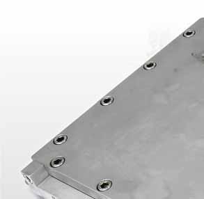
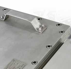
2 Local control stations for Zone 1 and Zone 21 Local control stations for Zone 1 and Zone 21 Features The right size/material enclosure Optimum functionality thanks to the great variety of components Customised planning and implementation Certified to many standards /B-02/12-BCS /1 Description For explosion-proof local controllers BARTEC offers an extensive range of polyester enclosures with screw fixing lid and hinged doors. BARTEC local control stations are certified for use in hazardous areas with combustible gas or dust. The enclosures must be produced in compliance with the requirements for the Increased Safety type of protection or Protection by Enclosure. Depending on the specification and number of equipment, various enclosure types and sizes are available. The control stations will be equipped according to your individual requirements with control units, alarm units, display units and bus interface modules. Industrial serial products can also be fitted in the controllers for Zone 21 with the td Protection by Enclosure type of protection. The components are mounted either on DIN rails or installed on the front lid. Depending on the design and requirements, BARTEC not only supplies control units but also offers the complete wiring to terminal blocks. The supply range includes enclosures made of aluminium, polyester and stainless steel. These are fitted with certified modules and glands at points of penetration in the wall of the enclosure. Fields of application Chemical and petrochemical industry, process and plant engineering, pharmaceutical and food industry, OFF SHORE areas. Thanks to their great variety, the enclosure are particularly suited for local control stations and bus interface units. 42
3 Local control stations for Zone 1 and Zone 21 Explosion protection Ex protection type (depending on the components installed) for Zone 1 II 2(1)G Ex demq ia/ib [ia] IIA, IIB, IIC T6, T5, T4 II 2G Ex demq ia/ib [ib] IIA, IIB, IIC T6, T5, T4 for Zone 21 II 2D Ex td [ibd] A21 IP 6X T80 C to T100 C (at a distance of 5 K) II 2(1)D Ex td [iad] A21 IP 6X T80 C to T100 C (at a distance of 5 K) Ambient temperature (special design on request) -20 C to +40 C -55 C to +70 C Certification PTB 02 ATEX 1159 for Zone 1 IBExU00ATEX1079 for Zone 21 IECEx PTB (Further certifications on request) Technical data Material Type with lid aluminium ALSi 12, pressure or chill casting RAL 7001 silver grey Type with lid glass-fibre reinforced polyester RAL 9005, deep black Type mit door glass-fibre reinforced polyester RAL 9011, graphite black Type with door High-quality stainless steel 304 Type with lid High-quality stainless steel 316L Enclosure with lid Type with door High-quality stainless steel 316L Seals EPDM (Standard) -20 C to +85 C PU (Standard at ) -20 C to +80 C Silicone -55 C to +100 C Mechanical strength (acc. to DIN EN : 2006) Impact energy 7 Nm Protection class (higher degree of protection on request) EN 60529/IEC max. IP 66 Electrical data Rated voltage up to 1000 V Rated curent max. 160 A depending on devices fitted max. 125 A (for Zone 21) Mounting dimensions for switching and light elements according to EN * Configuration data for control stations Type of enclosure Dimensions Width Height Depth 6 7 Nominal voltage AC V / DC V Threaded glands /B-02/12-BCS /2 * Recommended distance for mushroom pushbutton, emergency switch as well as position selector with protective shroud: 100 mm (3.94 in). 43
4 Local control stations for Zone 2 and Zone 22 Local control stations for Zone 2 and Zone 22 Features The right size/material enclosure Optimum functionality thanks to the great variety of components Customised planning and implementation Certified to many standards Description /A-02/12-BCS /1 For explosion-proof local controllers BARTEC offers an extensive range of polyester enclosures with screw fixing lid and hinged doors. The enclosures must be produced in compliance with the requirements for the Increased Safety type of protection or Protection by Enclosure. Depending on the specification and number of equipment, various enclosure types and sizes are available. The control stations will be equipped according to your individual requirements with control units, alarm units, display units and bus interface modules. Industrial serial products can also be fitted in the controllers for Zone 22 with the td Protection by Enclosure type of protection. The components are mounted either on DIN rails or installed on the front lid. Depending on the design and requirements, BARTEC not only supplies control units but also offers the complete wiring to terminal blocks. The supply range includes enclosures made of aluminium, polyester and stainless steel. These are fitted with certified modules and glands at points of penetration in the wall of the enclosure. Fields of application Chemical and petrochemical industry, process and plant engineering, pharmaceutical and food industry, OFF SHORE areas. Thanks to their great variety, the enclosure are particularly suited for local control stations and bus interface units. 44
5 Local control stations for Zone 2 and Zone 22 Explosion protection Ex protection type (depending on the components installed) for Zone 2 II 3G Ex na nc nl [nl] IIA, IIB, IIC T6, T5 or T4 II 3(1)G Ex na nc nl [ia] IIA, IIB, IIC T6, T5 or T4 II 3(2)G Ex na nc nl [ib] IIA, IIB, IIC T6, T5 or T4 for Zone 22 II 3D Ex td A22 IP 6X T 80 C to 100 C II 3(1)D Ex td [iad] A22 IP 6X T 80 C to 100 C II 3(2)D Ex td [ibd] A22 IP 6X T 80 C to 100 C Ambient temperature (special design on request) -20 C to +40 C -55 C to +70 C Technical data Material Type with lid aluminium ALSi 12, pressure or chill casting RAL 7001 silver grey Type with lid glass-fibre reinforced polyester RAL 9005, deep black Type mit door glass-fibre reinforced polyester RAL 9011, graphite black Type with door High-quality stainless steel 304 Type with lid High-quality stainless steel 316L Enclosure with lid Type with door High-quality stainless steel 316L Seals EPDM (Standard) -20 C to +85 C PU (Standard at ) -20 C to +80 C Silicone -55 C to +100 C Mechanical strength (acc. to DIN EN : 2006) Impact energy 7 Nm Protection class (higher degree of protection on request) EN 60529/IEC max. IP 66 Electrical data Rated voltage up to 1000 V Rated curent max. 160 A depending on devices fitted max. 125 A (for Zone 22) Mounting dimensions for switching and light elements according to EN * Configuration data for control stations Type of enclosure A Dimensions Width Height Depth 6 7 Nominal voltage AC V / DC V Threaded glands /A-02/12-BCS /2 * Recommended distance for mushroom pushbutton, emergency switch as well as position selector with protective shroud: 100 mm (3.94 in). 45

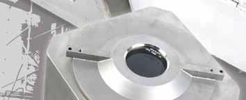
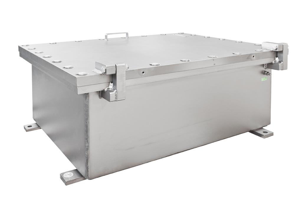
6 Control Stations TNCC The TNCC range of control stations / enclosures are manufactured in 316 stainless steel and designed to meet the requirements for use on and offshore, in petrochemical and marine applications and for any other industry where an explosive atmosphere may be present. Specifications Material Acid resistant Stainless steel AISI316L IP Rating IP66 standard (67 and 68 upon request) Temperature -40ºC to +60ºC Approvals - Atex DNV-2003-OSL-ATEX Brazilian 09/UL-BRCN GOST GOST Certificate Standards EN/IEC: , , , , EN: , Lid/Door gasket Neoprene (temp. -40ºC to +100ºC) Silicone (temp. -40ºC to +200ºC) Surface treatment Acidized Pickling as standard Electropolished as an option Material thickness Min. 1.5 mm (depending on the box size) Earthing Internal earth bar/bracket External earth bracket Drain Plug Optional Other options Ref. TNCN TNCC Measurement Range of Stocked Boxes Type A B C Volume Weight Width cm Height cm Depth cm dm 3 kg Dimensions 40

7 Limit Monitor for Zone and Zone Limit Monitor Description The limit value transmitters of Types /... are deployed in conjunction with pneumatic actuators on valves and fittings. They serve to signal the "open/closed" status of a fitting. This end position is communicated by means of up to a maximum of 6 limit switches in the Ex d type of protection or by means of 6 proximity initiators in conformance to NAMUR in the Ex i type of protection. In intrinsically safe proximity initiators there is a choice of slot initiators or V3 initiators. The limit monitors are available in polyester, aluminium and stainless steel. The metal versions can be used in temperatures down to -60 C depending on the fitted components. To ensure mechanical adaptability to the pneumatic actuators, we supply 4 consoles according to VDI/VDE The BARTEC limit monitors can be used in hazardous (potentially explosive) areas in Zone 1 and 2 in accordance with the certified explosion sub-groups IIA, IIB and IIC and the temperature classes T5/T6 and in Zone 21 and 22 in accordance with the certified max. surface temperature. Selection chart for Standard-Limit Monitors Console Dimensions (mm) Order no. A B H Aluminium enclosure black (220 x 120 x 90 mm) for Zone and Ex e d m Picture 1 Console VDI/VDE 3845 Console VDI/VDE 3845 Console VDI/VDE 3845 Console VDI/VDE A1-2209/ A1-2209/ A1-2209/ A1-2209/9002 Connection dimensions DIN EN ISO 5211 F05 without console 07-31A1-2209/9001 Polyester enclosure black (220 x 120 x 90 mm) for Zone and Ex e d m Picture 1 Console VDI/VDE 3845 Console VDI/VDE 3845 Console VDI/VDE 3845 Console VDI/VDE B1-2209/ B1-2209/ B1-2209/ B1-2209/9001 Connection dimensions DIN EN ISO 5211 F05 without console 07-31B1-2209/9007 Polyester enclosure black (110 x 75 x 55 mm) for Zone and /B-05/2014-BCS /1 Ex e d m Picture 2 Ex e d m Picture 3 Console VDI/VDE 3845 Console VDI/VDE 3845 Console VDI/VDE 3845 Console VDI/VDE B1-1105/ B1-1105/ B1-1105/ B1-1105/9002 Connection dimensions DIN EN ISO 5211 F05 without console 07-31B1-1105/9001 Stainless-steel enclosure (150 x 150 x 80 mm) for Zone and Console VDI/VDE 3845 Console VDI/VDE 3845 Console VDI/VDE 3845 Console VDI/VDE D1-1508/ D1-1508/ D1-1508/ D1-1508/9006 Connection dimensions DIN EN ISO 5211 F05 without console 07-31D1-1508/
8 Limit Monitor for Zone and Zone Explosion protection Ex protection type (max.) Certification dependent on the installed parts II 2G Ex e d mb ia or ib IIC T6 or T5 Gb II 2D Ex tb IIIC T90 C Db IBExU02ATEX1126 IECEx IBE Ambient temperature -60 C to max. +70 C Technical data Protection class Enclosure IP 65/67 according to EN and IEC Material Type 07-31A cast aluminium Type 07-31B polyester black Type 07-31D high quality stainless steel Mounting console and according to DIN EN ISO 5211 F05 connection dimensions resp. VDI/VDE 3845 Connection Ex glands M20 x 1.5 resp. M16 x Picture M M20 x 1,5x 1.5 Aluminium enclosure 220 x 120 x 90 mm Polyester enclosure 220 x 120 x 90 mm Picture 2 A - A 110 M16 x 1.5 Polyester enclosure 110 x 75 x 55 mm Built-in 2 microswitches A A B (H) Ex protection type Switching function Ex e d IIC changeover contact 120 Cable connection via Ex e modular terminals. An Ex e cable gland is provided for the cable connection M20 x 1.5 (6 to 12). The version with enclosure dimensions 220 x 120 x 90 mm optionally provides additional terminals for the connection of a magnetic valve. ø 14 A B (H) (H) 27 Built-in 2 micro-switches Ex protection type Switching function Ex e d IIC NO contact 7 75 The cable is connected to Ex e-rail-mounted terminals. An EEx e-cable gland is provided to insert the cable M16 x 1.5 (5 to 10). A A /B-05/2014-BCS /2 Picture (H) 80 B A 150 M20 x 1.5 Stainless-steel enclosure Fitted components 2 microswitches Ex protection type Switching function 150 x 150 x 80 mm Ex e d IIC Changeover contact The cable is connected to Ex e-rail-mounted terminals. An Ex e-cable gland is provided to insert the cable M16 x 1.5 (6 to 12). 49

9 Flameproof control unit Ex d for Zone 1 and 2 Features Variety of covers Variety of connection possibilities Bushings can be fitted on all sides Flameproof control unit Flange surfaces for mounting enclosures Low weight Description As flameproof control unit, this Ex d enclosure from BARTEC provides a compact solution for the installation of standard industrial products, whereby components such as contactors and relays are installed in a flameproof enclosure. The enclosure is light, flexible with respect to wiring systems, may be flange mounted and can be equipped with electrical or mechanical line bushings on the sides and in the lid. The different versions of lids enable the installation of display units or devices with control buttons. The installation of Ex i assemblies is also permitted. Types of connection Flameproof control units may be connected either with direct cable entry by means of Ex d cable glands or indirectly using an Ex e junction box. The electrical connection between Ex d and Ex e area takes place using Ex d line bushings with terminals. Control devices and display units can be installed in the junction box. Note: The use of an empty enclosure requires an acceptance inspection by a notified body. Explosion protection Ex protection type max. Dependent on the installed components; Observe the information on the type label. ATEX Ex protection type II 2 G Ex db eb ia/ib [ib] IIA, IIB resp. IIC T6, T5 resp. T4 II 2 (1) G Ex db eb ia/ib [ia] IIA, IIB resp. IIC T6, T5 resp. T4 Certification Ex d control unit PTB 03 ATEX 1138 Empty enclosure PTB 03 ATEX 1137 U IECEx Ex protection type Ex db eb ia/ib [ib] IIA, IIB resp. IIC T6, T5 resp. T4 Ex db eb ia/ib [ia] IIA, IIB resp. IIC T6, T5 resp. T4 Certification Ex d control unit IECEx PTB Empty enclosure IECEx PTB U Ambient temperature Dependent on the installed components; Observe the information on the type label. Operating temperature -20 C to +55 C Approved for Zone 1 and 2 Technical data Power dissipation max. 67 W (depending on version and type of protection) Protecion class max. IP 54 (IEC 60529) Rated cross-section of conductor max. 16 mm² Weight approx. 4 kg (depending on the version) Enclosure material aluminium Rated voltage max. 690 V Rated current max. 104 A /A-01/2014-BCS /1 48
10 Flameproof control unit Ex d for Zone 1 and /A-01/2014-BCS /2 I = 143 II = 154 ø I = 107 II = L x 60 ø ø 135 ø M4 x x ø , Versions to specification, please give particulars in pain text

11 Control stations in flameproof enclosures for Zone and for Zone Control stations in flameproof enclosures Dimensions Mounting plate 6 b B a A Dimensions /A-07/10-BCS /1 L H I Description The control stations in flameproof enclosure of the GUB series in compact design allow standard electronics and control components to be installed. The enclosure is light; numerous connection systems can be used; flanging is possible; can be equipped with electrical or mechanical bushings at the edges. Explosion protection Ex protection type II 2D Ex td A21 [ia] IP 66 T85 C or 100 C II 2(1)G Ex de [ia] IIC T6 or T5 Certification KEMA 08 ATEX 0123 The GUB control stations can be applied in hazardous areas, Zone 1 and Zone 2 as well as in areas endangered by flammable dusts, Zone 21 and Zone 22. Technical data Protection class IEC max. IP 66 Enclosure material copper-free aluminium pressure casting Surface Acrylic varnish, similar to RAL 7016 Electrical connection Directly through cable entry or cable gland or mounted Ex e enclosure i H S b b2 B 50
12 Control stations in flameproof enclosures for Zone and for Zone Enclosure Type Order no. Dimensions (mm) Weight (kg) B b b2 H I i L S 1 GUB GUB GUB GUB GUB GUB Mounting plate 3 Type Enclosure A B a b GUB GUB GUB GUB GUB GUB Selection chart 4 5 Enclosure size Code no. Cover variants Code no. 120 x 120 GUB x 150 GUB 0 closed x 174 GUB x 230 GUB x 276 GUB x 430 GUB 04 with window only for GUB 0, GUB 01, GUB 02, GUB Complete order no. Please enter code number. Technical date subject to change withiout notice /A-07/10-BCS /2 51

13 Flameproof control panels Ex de IIC Control and switchgear units with metal flameproof enclosures Description These BARTEC enclosures offer a variety of options for control equipment in Ex areas. Flameproof enclosures in compliance standard with EN are available for electrical devices such as contactors, relays, barriers, electronic controllers and PLC-D/A-modules. BARTEC flameproof cable bushings are provided for cable interconnections between the Ex d & EEx e enclosures. Inside the Ex e enclosure the conductors are connected to Ex e terminal blocks The pushbuttons, switches and LEDs are located on the cover of the EEx e enclosure. Explosion protection Ex protection type max. depends on the fitted components; observe the specifications on the type label II 2G Ex de ia/ib [ia] IIA, IIB, IIC T6, T5, T4 II 2G Ex de ia/ib [ib] IIA, IIB, IIC T6, T5, T4 Certification PTB 03 ATEX 1024 Ambient temperature -20 C to +40 C Technical data Power dissipation max. 80 W to 1350 W (depends on the version and type of protection) Protection class according to IEC IP 54 (IEC 60529) IP 66 on request Rated cross-section of conductor up to 300 mm 2 Weight approx. 8 kg to approx. 320 kg Mechanical strength Impact energy max. 7 Nm /A-10/10-BCS-A201191/1 52
14 Flameproof control panels Ex de IIC Dimensions Selection chart (Dimensions in mm) A B C D E F G H J K x ø x ø x ø x ø x ø x ø x ø x ø x ø x ø /A-10/10-BCS-A201191/ x ø x ø Version without inspection window. If required, the d enclosure can be supplied with an inspection window. (Please ask!) 53


15 Flameproof control units Ex d IIB Ex d control units /A-05/11-BCS-A201191/3 Features Standard components Cost-effective; also applies to spare parts Easy-to-service Expandible Description The BARTEC ATEX certified Ex d control panels are constructed according to protection type Ex d, flameproof encapsulation. Standard components such as switches, contactors and relays are mounted in an explosionproof enclosure constructed in such a way as to keep internal explosions from igniting the surrounding atmosphere. Ex d control panels are usually custom-built in close cooperation with the customer himself for his special application. Version Flameproof control panels are available either with direct cable-entries through Ex d cableglands or with indirect cable-entries through a junction box with protection type increased safety Ex e. The electrical wiring between Ex d and Ex e enclosure will be done through Ex d line bushings. Fields of application Zone and zone Gas groups IIA and IIB Temperature class T4/T5 or T6 Explosion protection Explosive atmospheres can occur wherever flammable gases, liquids or materials are processed, transported and stored. It is therefore necessary to take appropriate measures to prevent possible explosions. BARTEC protects people and the environment by the safety of components, systems and plant safe. When the 94/9/EC (ATEX 95) guideline comes into force on 01/07/2003, explosion protected operating equipment must be properly installed in accordance with EN Our safety standards comply to the national directives for commissioning, maintenance and repair of electrical devices; construction and manufacturing according to the CENELEC standards EN /EN / EN /EN Three Ex groups of flammable gases can be introduced following safety gaps and/or minimum ignition currents determined in experiments. IIA e. g. ethane, methane, petrol IIB e. g. ethylene, dimethylether, towngas IIC e. g. hydrogen, acethylene, sulphur carbonate Further selection criteria is the categorizing into temperature classes. The device temperature is added to a supposed ambient temperature of +40 C and divided in the following six temperature classes: T C T C T C T C T C T6 +85 C 54
16 Flameproof control units Ex d IIB Explosive areas have three different zones: Zone 0 (Category 1G-devices necessary) A place in which an explosive atmosphere consisting of a mixture with air of flammable substances in the form of gas, vapour or mist is present continuously, for long periods or frequently. Zone 1 (Category 1G- or 2G-devices necessary) A place in which an explosive atmosphere consisting of a mixture with air or flammable substances in the form of gas, vapour or mist is likely to occur in normal operation occasionally. Zone 2 (Category 1G-, 2G- or 3G-devices necessary) A place in which an explosive atmosphere consisting of a mixture with air of flammable substances in the form of gas, vapour or mist is not likely to occur in normal operation but, if it does occur, will persist for a short period only. Electrical control panels contain switches, relays, pushbutton etc. which may produce a spark when they switch. In order to keep such sparks or other hot spots from causing an explosion, the components are housed within flameproof enclosures. Explosion protection Ex protection type II 2G Ex d...iib, IIB+H2 T6 or T4 II 2(1, 2 or 3)G Ex d...iib, IIB+H2 T6 or T5 II 2D Ex td...a21 IP6X T80 C to T130 C II 2(1, 2 or 3)D Ex td...a21 IP6X T80 C to T130 C Certification KEMA 08 ATEX 0123 Selection chart Technical data Nominal voltage AC 1000 V DC 1500 V Operating voltage 25 kv Rated current 1000 A Protection class IP 65/IP 66/IP 67 Material Alumium alloy < (Cu 0.05%) Stainless steel Name Dimensions (mm) outside Dimensions (mm) inside empty weight width height depth width height depth kg EJB EJB EJB EJB 3B EJB EJB 4B EJB EJB 45B EJB EJB 5B EJB EJB EJB 55B EJB /A-05/11-BCS-A201191/4 EJB 6B EJB EJB 7B It is possible to combine the various enclosures. 55


17 Flameproof enclosures


18 Flameproof Enclosures TNCD/TNBCD The TNCD / TNBCD range comprises of many standard sizes of enclosures manufactured in stainless steel 316L/CF-3M, for maximum environmental protection. The enclosures allow for standard electrical components inside. Thus subsequent replacement and maintenance of the installed components is easy, and may be performed by skilled electricians. If required, several enclosures may be assembled on a framework, with separate or common Ex e/i connection boxes. The enclosures can be delivered empty with U-component certificate, or supplied fully assembled according to client s demands. Applications The TNCD / TNBCD range of enclosures are designed to meet the harsh environments of the North Sea and are also ideal for Petrochemical and Marine applications as well for all kind of industry where an explosive atmosphere may be present. Thousands of BARTEC TECHNOR enclosures are installed on- and offshore. If you should have a particular need, our sales staff will be happy to advise on this. General Specifications Material Stainless steel 316L/CF-3M IP rating TNCD IP66 (IP67 upon request) IP Rating TNBCD IP66 (IP67 and IP68 upon request) Temperature TNCD -20 C C, option -40 C C Temperature TNBCD -20 C C, option -50 C C Approvals TNCD - Atex * Component NEMKO 03ATEX263U * Complete DNV-2003-OSL-ATEX-0135 * IEC IECEx NEM U Approvals TNBCD - Atex * Component NEMKO 03ATEX264U * Complete DNV-2003-OSL-ATEX-0136 * IEC IECEx NEM U costs Standards EN/IEC: , Ex-Code II 2 G/D or II 2(1/2)G/D - TNCD Ex d IIC T6 T4 - TNBCD Ex d IIB T6 T4 Surface treatment Shot blasted Earthing between Ex d and Ex e/i enclosures Through the flange assembly Lid With or without hinges, depending on size
19 I = A IP Flameproof Enclosures TNCD/TNBCD Viewing window TNCD The window is placed in centre of the lid. Windows (ø65) can also be placed on the sides or back wall. Viewing windows are available with the following diameters: 65mm, 100mm and 154mm. Enclosure type Maximum window diameter TNCD 1919XX 65mm TNCD 2828XX 100mm TNCD 3838XX 100mm TNCD 5757XX 154mm Measurement table for Ex d IIC Explosion proof enclosures External dimensions Internal dimensions Fixing dimensions TNCD Wide A Height B Depth C Total Depth D Lid aperature Wide a Height b Depth c Kg H I Measures in mm. Other sizes upon request. Measurement table for Ex e connection boxes TNCC E (Wide) F (Heigth) G (Depth) Kg , , , ,6 TNCC E (Wide) F (Heigth) G (Depth) Kg , , , ,7 Measures in mm. Other sizes upon request. Type: TNCD STAVANGER NORWAY 0470 II 2G Ex db II C T NEMKO 03ATEX 263U U = V T.amb S.No./Year SEE INSTALLATION INSTRUCTION DOCUMENT


20 Flameproof Enclosures TNCD/TNBCD Measurement table for Ex d IIB Explosion proof enclosures TNBCD Wide A External dimensions Internal dimensions Fixing dimensions Height B Depth C Total Depth D Window Mounting plate / / /100/ /100/ Measures in mm. Other sizes upon request. Wide a Height b Depth c Kg L1 H1 L H Measurement table for Ex e connection boxes TNCC E F G Measures in mm. Control and indication equipment can be fitted directly into the cover of an Ex d enclosure, or in the Ex e connection box.
21 Type: TNBCD DNV-2003-OSL-ATEX-0136 U = V T.amb I = A S.No./Year STAVANGER NORWAY 0470 Ex d II B T IP DO NOT OPEN WHEN ENERGIZED Flameproof Enclosures TNCD/TNBCD Options: Ex d enclosure with windows in lid (ø65 or ø100) or base (ø65). Lamps or switches in lid or base, for Ex d enclosure, as well as Ex e enclosure. * Option: Without hinges but with a support below the lid. (Holding the lid in correct position while fitting) Material Stainless steel 316L.


 (Category 3) An area in which explosive gas is likely to")


22 Flameproof Enclosures TNCD/TNBCD Hazardous area information & terminology ATEX Directive The ATEX Directive, derived from the French AT mosphères EXplosibles and formally known as 94/9/EC, contains the ESR (Essential Safety Requirements) to which electrical equipment and protective systems used within potentially explosive atmospheres must conform. The new ATEX Directive currently in place within the European Union was made mandatory on 1st July Primarily intended for manufacturers of hazardous area equipment for use in the presence of flammable gases, vapours, fumes or dusts, the new directive requires a quality management system to be implemented. Procedures for the design, manufacture and verification of products are to be approved by a notified body (i.e. DNV, NEMKO, etc.) and all equipment conforming to the new directive will feature CE and Ex Marking. Zone Classification with the presence of GAS (Category 2) (Category 3) An area in which explosive gas is likely to be present during normal operation of the plant. An area in which explosive gas is not continuously present, but may exist for a short period of time. Applicable EX protection Ex d Protection Parts, which can ignite a potentially explosive atmosphere, are surrounded by an enclosure, which are designed to withstand the pressure of an internal explosion and to prevent the propagation of the explosion to the atmosphere surrounding the enclosure. Ex e Protection for electrical components that do not spark under normal working conditions but where measures are applied to prevent high temperatures and the occurence of arcs and sparks internally.

23 Flameproof Enclosures
24 Flameproof Enclosures DE8BC The DE8BC range comprises many standard sizes of enclosures manufactured in stainless steel 316L and/or in painted carbon steel. The enclosures allow for utilization of standard electrical components inside. Thus subsequent replacement and maintenance of the installed components is easy, and may be performed by skilled electricians. If required, several enclosures may be assembled on a framework, with separate or common Ex e/i junction boxes. The enclosures can be delivered empty with U- component certificate or supplied fully assembled according to client demands. Flexible product range with many standard sizes. Ingress protection IP66 to meet harsh environment. Suitable for demanding environments. Wide temperature range (-20 C to +60 C). Many cable entries possibilities. Several earthing alternatives. May be used with a Ex e/i connection box Window in lid/door may be fitted in IIB version. High operational reliability and cost efficiency, reduced lifetime maintenance costs. ATEX approved. Applications The DE8BC range of enclosures are designed to meet the requirements for use at the on- and offshore market, and are ideal for Petrochemical plants and other kinds of industry where an explosive atmosphere may be present. For particular needs, please contact our sales staff. General Specifications Material Stainless steel 316L or carbon steel as option IP rating IP66 Temperature -20 C to +60 C - Option -40 C to +60 C Approvals: Component enclosure DE8BC INERIS09ATEX9017U Standards EN: , , Ex-Code II 2 GD or 2[1]GD Ex d IIB T6 to T4 - T85 C to T135 C, Ex d [ia] ia or de [ia] ia IIB T6 IP65 T85 C Surface treatment DE8BC SS316L is shot blasted DE8BC carbon steel version is RAL 7032 painted - special painting on request. Earthing M10 Drain plug Upon request
25 Flameproof Enclosures DE8BC
26 Flameproof Enclosures DE8BC Measurement table for Ex d IIB Explosion proof enclosure DE8BC... Reference DE8BC Width A Height B Depth C Useful Depth C1 External fixing (H1xL1) Diameter of fixing holes Base plate useful surface (HxL) (fixing holes) Max. heat dissipation (W) Weight (kg) DE8BC x326 Ø x DE8BC x346 Ø x DE8BC x426 Ø x DE8BC x526 Ø x DE8BC x526 Ø x DE8BC x526 Ø x DE8BC x630 Ø x DE8BC x734 Ø x DE8BC x868 Ø x DE8BC x868 Ø x DE8BC x900 Ø x All dimensions in mm Dimension tolerance: ± 5 mm
27 Flameproof Enclosures TNCC Measurement table for Ex e II Increased safety enclosures TNCC Reference Width A Height B Depth C No of command and signal unit No of Ammeter Max. heat dissipation (W) TNCC TNCC Weight (kg) TNCC TNCC Dimension precision: ± 5 mm Assembly possibilities between DE8BC and TNCC DE8BC TNCC X X X X X X X X X TNCC X X X X X X X X TNCC X X X X TNCC X X X X: possibility of combination
 to which electrical equipment and protective systems used within potentially explosive atmospheres must conform.")
28 Flameproof Enclosures DE8BC Hazardous area information & terminology ATEX Directive The ATEX Directive, derived from the French AT mosphères EXplosibles and formally known as 94/9/EC, contains the ESR (Essential Safety Requirements) to which electrical equipment and protective systems used within potentially explosive atmospheres must conform. The new ATEX Directive currently in place within the European Union was made mandatory on 1st July Primarily intended for manufacturers of hazardous area equipment for use in the presence of flammable gases, vapours, fumes or dusts, the new directive requires a quality management system to be implemented. Procedures for the design, manufacture and verification of products are to be approved by a notified body (i.e. DNV, NEMKO, etc.) and all equipment conforming to the new directive will feature CE and Ex Marking. Zone Classification with the presence of GAS Zone 1 (Category 2) Zone 2 (Category 3) An area in which explosive gas is likely to be present during normal operation of the plant. An area in which explosive gas is not continuously present, but may exist for a short period of time. Zone Classification with the presence of DUST Zone 21 Zone 22 An area in which an explosive atmosphere in the form of a cloud of combustible dust in air is likely to occur in normal operation of the plant. A place in which an explosive atmosphere in the form of a cloud of combustible dust in air is not likely to occur in normal operation, if it does occur, will persist for a short period only. Applicable EX protection Ex d Protection Parts, which can ignite a potentially explosive atmosphere, are surrounded by an enclosure, which are designed to withstand the pressure of an internal explosion and to prevent the propagation of the explosion to the atmosphere surrounding the enclosure. Ex e Protection for electrical components that do not spark under normal working conditions but where measures are applied to prevent high temperatures and the occurence of arcs and sparks internally. DOC.NO.: 75-DIV-5, REV JUNE 2013


29 Flameproof enclosures

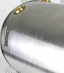
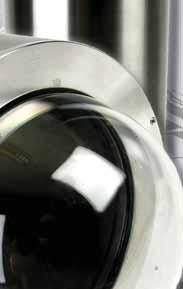
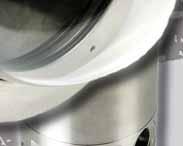
30 Flameproof Enclosures TNXCD Features BARTEC TECHNOR s cylindrical Ex d/de certified enclosures, manufactured in stainless steel 316L/CF-3M, are more cost efficient than traditional Ex d enclosures. The design makes the unit easy to install and use, and also allows for simple solutions within numerous different applications. The enclosures can be delivered empty with U-component certificate or supplied fully assembled according to clients demands. Applications The TNXCD range of enclosures are designed to meet the harsh environments of the North Sea, and are ideal for Petrochemical and Marine applications as well as for all kind of industry where an explosive atmosphere may be present. Thousands of BARTEC TECHNOR enclosures have been installed on- and offshore. If you should have a particular need our sales staff will be pleased to advise. standard. sizes costs. (PCB) General specification Material Stainless steel 316L/CF-3M IP Rating IP66 (IP67 and IP68 upon request) Temperature Various, max: -50 C to +60 C Approvals - Atex, Empty enclosure DNV-2003-OSL-ATEX-0436U - Atex, complete enclosure DNV-2004-OSL-ATEX-0115 Standards EN/IEC: , , EN Ex-Code for empty enclosure: II 2 G, Ex d/de IIC Ex-Code for complete enclosure: Entries Gland Size Ex e Gland Size Ex d Bushings Ex d Earthing between Ex d and Ex e enclosures II 2 G / D, Ex d/de IIC Option: Ex dem ia/ib [opis] T6-T4 Ex e glands and Ex d bushings, or Ex d glands only M25 According to specification Max M42, number and core size acc. to spec. Through the flange assembly TNXCD Ex d enclosures allow for utilization of standard electrical components. Subsequent replacement and maintenance of installed components is thus easy. The Ex d enclosures and components are designed, built and delivered in full compliance with current specifi cations and standards. The client receives a complete system including user manual, part list, wiring diagram and an EC-Declaration of Conformity. We can also deliver empty enclosures with U- component certificate. The client performs installation of electrical equipment and subsequently applies to the Certifying Authority (Notified Body) for full Certificate of Conformity according to ATEX 94/9 EC directive. TNXCD enclosures are manufactured in the following standard diameters: 100, 130, 155 and 195 mm. Enclosure lengths are according to measurement table. The enclosures can be delivered with or without an inspection window in the front, or a dome. Ex d enclosures normally are delivered in combination with an Ex e/ex i connection box. Incoming and outgoing cables are terminated in the connection box. Standard TNXCD connection boxes are available in several sizes. If there is a need for a bigger connection box, all Ex approved BARTEC TECHNOR TNCN boxes can be used. If required, it is also possible to have a direct entry by use of Ex d glands. In this case the Ex d enclosure is delivered without a connection box.
 Weight (kg) Window/dome (mm) XCD1003200 T3 212 193 101 95 3,3 68 XCD1003360 T3 379 360 101 95 4,1 68 XCD1303200 T3 219 200 132 126 4,0 95* XCD1303360 T3 379 360 132 126 7,0 95* XCD1553184 D10")
31 Flameproof Enclosures TNXCD TNXCD100 TNXCD130 TNXCD195 TNXCD Ex d A B C D Ø TNXCD Total length (mm) Tube length (mm) Diameter (mm) Internal dia. (mm) Weight (kg) Window/dome (mm) XCD T ,3 68 XCD T ,1 68 XCD T ,0 95* XCD T ,0 95* XCD D ,0 107 XCD T ,0 155 TNXCD Ex de A B C D Ø TNXCD Total length (mm) Tube length (mm) Diameter (mm) Internal dia. (mm) Weight (kg) Window/dome (mm) XCD T ,9 68 XCD T ,8 68 XCD T ,6 95* XCD T ,9 95* XCD T ,0 107 XCD T ,1 155 Available with window, dome or SS316L top * Dome not available
 to which electrical equipment and protective systems used within potentially explosive atmospheres must conform.")

 and all equipment conforming to the new directive will feature CE and Ex Marking.")
32 Flameproof Enclosures TNXCD Hazardous area information & terminology ATEX Directive The ATEX Directive, derived from the French AT mosphères EXplosibles and formally known as 94/9/EC, contains the ESR (Essential Safety Requirements) to which electrical equipment and protective systems used within potentially explosive atmospheres must conform. The new ATEX Directive currently in place within the European Union was made mandatory on 1st July Primarily intended for manufacturers of hazardous area equipment for use in the presence of flammable gases, vapours, fumes or dusts, the new directive requires a quality management system to be implemented. Procedures for the design, manufacture and verification of products are to be approved by a notified body (i.e. DNV, NEMKO, etc.) and all equipment conforming to the new directive will feature CE and Ex Marking. Zone Classification with the presence of GAS (Category 2) (Category 3) An area in which explosive gas is likely to be present during normal operation of the plant. An area in which explosive gas is not continuously present, but may exist for a short period of time. Applicable EX protection Ex d Protection Parts, which can ignite a potentially explosive atmosphere, are surrounded by an enclosure, which are designed to withstand the pressure of an internal explosion and to prevent the propagation of the explosion to the atmosphere surrounding the enclosure. Ex e Protection for electrical components that do not spark under normal working conditions but where measures are applied to prevent high temperatures and the occurence of arcs and sparks internally.
. Within the scope of the EC model test certification, these can be fitted with industrial standard units, such as e.g.")
33 Control, regulating and display devices Control, regulating and display devices Description BARTEC offers two type series of explosion proof encapsulated enclosures for using electric components in hazardous (potentially explosive areas). Within the scope of the EC model test certification, these can be fitted with industrial standard units, such as e.g. small-type motors, printed circuit boards and cameras. The mounted parts are evaluated by BARTEC, fitted into a suitable housing and provided as a complete device with the corresponding ATEX marking. This housing series offers optimum solution approaches for control, regulating and display devices in Zone 1 and zone 21 hazardous areas. Explosion protection Ex protection type Typ V < 100 cm 3 II 2G Ex de IIC T6/T5 II 2D Ex td A 21 IP 66 T 80 C or T 95 C PTB 03 ATEX 1026 Typ cm 3 < V < 2750 cm 3 II 2G Ex de [ia/ib] IIC T6, T5 or T4 II 2D Ex td [iad/ibd] A21 IP 6X T 80 C or T 95 C PTB 03 ATEX 1051 Technical data Protection class min. IP 54/IEC Enclosure material Metall Surface bare, electro-plated or varnished /A-07/10-BCS /1 56


34 ontrol, regulating and display devices Description The control, regulating- and display devices are assembled out of the following modules to suit the required function. The size of the equipment depends on the components, power dissipation and the required housing volume. 1 Selection chart 2 Front flange Enclosure Rear flange closed e. g. for vibration measuring instrument or printed circuit board installation 30 mm to max. 25 cm 3 volume 45 mm to max. 100 cm 3 volume 60 mm to max. 200 cm 3 volume 90 mm to max cm 3 volume with multicore tube encapsulated directly in the housing only up to a maximum 60 mm housing diameter mm to max cm 3 volume 4 5 with cable entry with shaft bushing e. g. for small motors, rotary encoders or switches 6 with Ex d screwed cable gland 7 not suitable for gas subgroup IIC when sparking parts have been fitted. with inspection glass e. g. for cameras, optoelectronic units Displays Flange with Ex e connection housing /A-07/10-BCS /2 57

35 Potentiometer max. 4 W with individual leads /A-10/10-BCS /1 Features High IP-protection class Small design Simple installation Potentiometer Description These up to 4 W potentionmeters show that Ex potentiometers can be small and compact. The external dimensions are approximately the same as those of standard industrial potentiometer enclosures. Central fixing in a single hole and the standard size of shaft have been includend. From the variety of resistors on the market we have chosen cemented wire-wound resistors and carbon film resistors and developed a standard-program range.the metal Ex d enclosures are tailored to the dimensions of the resistors and feature a standard 30 mm diameter. The potentiometers have been designed so that the stated nominal capacities can be fully exploited at temperature class T6 or T5 and be deployed in zones 1 and 2. They can be fastened and secured against twisting in a number of ways. Two nuts are included in each consignment. At an extra charge BARTEC provides either threaded holes in the front panel of the enclosure or an antirotation pin. The length of the encapsulated numbered cores can be specified by the customer. The potentiometers are Ex-certified by means of a PTB component certificate. If potentiometers have connecting wires, these must be laid with protection. We have developed terminals and enclosures especially for proper connection of the ends of the wires in explosive atmospheres. The most important data, such as resistance values, power ratings and dimensions can be found in the table on the right. We also supply accessories, such as rotary and pointer knobs, scales and slip couplings. Explosion protection Ex protection type II 2G Ex d IIC I M2 Ex d I Certification PTB 03 ATEX 1025 U Temperature class T6 to T4 Ambient temperature -55 C to +40 C/+60 C/+80 C Technical data Protection class min. IP 54/IEC Enclosure nickel-plated brass (CuZn) Tightning torque (for nuts) 200 Ncm Resistance characteristic linear Electrical connection cores GNYE 4GAF Cemented wire-wound resistors: Resistance values/power ratings see selection chart Resistance tolerance ± 5 % Linearity tolerance max. 3 % of final value Insulation resistance 100 MΩ Rotation electr./mech. 250 /270 End stop strength 30 Ncm Weight with cores (0.5 m) 180 g Carbon-film resistors on ceramic: Resistance values/power ratings see selection chart Insulation resistance 100 MΩ Rotation electr./mech. 270 End stop strength 100 Ncm Weight with cores (0.5 m) 200 g Precision wire-wound resistors: Resistance values/power ratings see selection chart Insulation resistance 1000 MΩ Resistance tolerance ± 5 % Linearity tolerance to 500 Ω ± 1 % > 500 Ω ± 0.5 % Rotation electr./mech. 320 End stop strength 100 Ncm Weight with cores (0.5 m) 170 g 58
36 Potentiometer max. 4 W with individual leads Dimensions in mm Selection chart Cemented wire-wound resistors for high power ratings M12 x 1, , Resistor type/ standard resistance values (stock items printed bold) Cemented wire-wound resistors higher power ratings 10 Ω 68 Ω 470 Ω 3.3 k Ω 12 Ω 82 Ω 560 Ω 3.9 k Ω 15 Ω 100 Ω 680 Ω 4.7 k Ω 18 Ω 120 Ω 820 Ω 5.6 k Ω 22 Ω 150 Ω 1 k Ω 6.8 k Ω 27 Ω 180 Ω 1.2 k Ω 8.2 k Ω 33 Ω 220 Ω 1.5 k Ω 10 k Ω 39 Ω 270 Ω 1.8 k Ω 47 Ω 330 Ω 2.2 k Ω 56 Ω 390 Ω 2.7 k Ω Temperature class/ power rating T6/2.5 W resp. T4/4 W Complete order no. (indicate resistance values in plain text) resp Carbon-film resistors Precision wire-wound resistors M12 x 1, , Carbon film resistors 100 Ω 1 k Ω 10 k Ω 100 k Ω 220 Ω 2.2 k Ω 22 k Ω 220 k Ω 470 Ω 4.7 Ω 47 k Ω 470 k Ω 1 M Ω Precision wire-wound resistors 10 Ω 100 Ω 1 k Ω 10 k Ω 20 Ω 200 Ω 2 k Ω 20 k Ω 50 Ω 500 Ω 5 k Ω T6/2 W T6/1.2 W Lead length: 100 mm up to 1000 mm In 100-mm steps 5 = standard 500 mm Special versions - please indicate particulars in plain text Anti-rotation pin on front of enclosure Side entry of leads Threaded holes on front of enclosure Other resistance values 7 Accessories/Order no. Rotary knob shaft 6 mm Order no Pointer knob shaft 6 mm Order no Scale Order no (270 ) Order no (320 ) Slip clutch adjustable to 50 Ncm, shaft 6 mm Order no /A-07/10-BCS /

37 Potentiometer max. 8 W with cable tail Potentiometer /A-07/10-BCS /1 Features High IP-protection class Simple installation No further approvals required Description This standard range of up to 8 W potentiometers with wire-wound resistors show that Ex potentiometers can be small and compact. The external dimensions are approximately the same as those of standard industrial potentiometer enclosures. Central fixing in a single hole and the standard size of shaft have been included. From the variety of resistors on the market we have chosen the most commonly used types and developed a standard program range. The metal Ex d enclosures are tailored to the dimensions of the resistors and feature a standard 30 mm diameter. The potentiometers have been designed so that the stated nominal capacities can be fully exploited at temperature class T6 or T5 and be deployed in zones 1 and 2. They can be fixed and protected against turning in different ways. Two nuts are included in each consignment. At an extra charge BARTEC provides either threaded holes in the front panel of the enclosure or an antirotation pin. For the correct connection of the cable ends we have developed special Ex terminals and enclosures. The most important data such as resistance values, power ratings and dimensions can be found in the table on the right. We also supply accessories such as rotary and pointer knobs, scales and slip clutches. In addition to the standard models all other versions such as tandem potentiometers, potentiometers with microswitches, non-standard shafts or larger resistor diameters can be encapsulated in enclosures of up to 120 mm diameter. Explosion protection Ex protection type II 2G Ex d IIC T6 resp. T5 Certification PTB 03 ATEX 1026 Ambient temperature -20 C to +70 C Technical data Protection class min. IP 54/IEC Enclosure metal Tightening torque (for nuts) 200 Ncm Resistance characteristic linear Electrical connection cable H05VV-F4G 0.75 GY BK BN GNYE Cemented wire-wound resistors Resistance values/power ratings See selection chart Resistance tolerance ± 5 % Linearity tolerance max. 3 % of final value Insulation resistance 100 MΩ Rotation electr./mech. 250 /270 End stop strength 30 Ncm Weight with cable (1 m) 2.5 W 6 W 8 W 250 g 320 g 550 g Carbon-film resistors on ceramic Resistance values/power ratings see selection chart Insulation resistance 100 MΩ Rotation electr./mech. 270 End stop strength 100 Ncm Weight with cable (1 m) 240 g Precision wire-wound resistors Resistance values/power ratings see selection chart Resistance tolerance 1 turn ± 5 % / 10 turns > 50 Ω ± 3 % Linearity tolerance 1 turn to 500 Ω ± 1 % > 500 Ω ± 0.5 % 10 turns potentiometer ± 0.25 % Insulation resistance min MΩ Rotation electr./mech. 1 turn 320 ± 2 10 turns 10 x Weight with cable (1 m) 1 turn 210 g/10 turns 300 g End stop strength 1 turn 100 Ncm/10 turns 30 Ncm 60
38 Potentiometer max. 8 W with cable tail Dimensions in mm e c f 20 b d 0.8 a Selection chart Resistor type/ standard resistance values (stock items printed bold) Temperature class/ power rating 1 a b c d e f M12 x M12 x M12 x Cemented wire-wound resistors higher power ratings 10 Ω 180 Ω 3.3 k Ω 12 Ω 220 Ω 3.9 k Ω 15 Ω 270 Ω 4.7 k Ω 18 Ω 330 Ω 5.6 k Ω 22 Ω 390 Ω 6.8 k Ω 27 Ω 470 Ω 8.2 k Ω 33 Ω 560 Ω 10 k Ω 39 Ω 680 Ω 12 k Ω 47 Ω 820 Ω 15 k Ω 56 Ω 1 k Ω 18 k Ω 68 Ω 1.2 k Ω 20 k Ω 82 Ω 1.5 k Ω 22 k Ω 100 Ω 1.8 k Ω 27 k Ω 120 Ω 2.2 k Ω 30 k Ω 150 Ω 2.7 k Ω to 10 k Ω to 20 k Ω to 30 k Ω T6/2.5 W resp. T5/3 W T6/5 W resp. T5/6 W T6/7 W resp. T5/8 W resp resp resp M12 x Carbon-film resistors 100 k Ω 100 Ω 1k Ω 10 k Ω 220 k Ω 220 Ω 2.2 k Ω 22 k Ω 470 k Ω 470 Ω 4.7 k Ω 47 k Ω 1 M Ω Precision wire-wound resistors 10 Ω 100 Ω 1 k Ω 10 k Ω 20 Ω 200 Ω 2 k Ω 20 k Ω 50 Ω 500 Ω 5 k Ω T6/2 W T6/1.2 W / turns potentiometer* 20 Ω 500 Ω 10 k Ω 50 Ω 1 k Ω 20 k Ω 100 Ω 2 k Ω 50 k Ω 200 Ω 5 k Ω 100 k Ω T6/2 W Lead length: 5 = standard 500 mm 0 = length in plain text 7 Special versions, Please indicate particulars in plain text Anti-rotation pin on front of enclosure Threaded holes on front of enclosure Side entry of cable Other resistance values Accessories/Order no /A-07/10-BCS /2 Rotary knob shaft 6 mm Pointer knob shaft 6 mm Order no Order no *Max. wall thickness for installing a switch panel = 2.5 mm scale Order no (270 ) (320 ) 44 More turn drive* shaft 6.35 mm Order no Slip clutch,adjustable to 50 Ncm, shaft 6 mm Order no

39 Standard Motor Control Features Enclosure with Ex d type of protection with Ex e junction box enclosure Compact solution Short delivery periods Zones 1, 2 and 21, 22 Standard Motor Control /2014-BCS /1 Description The standard motor controls consist of an enclosure in the flameproof type of protection and a junction box in the increased safety type of protection. The motor starters are fitted into the enclosure with the flameproof enclosure type of protection. Depending on the order, controls are fitted into the junction box with the increased safety type of protection. The motor control units are supplied with a main switch and controls as standard. The standard versions with control transformer conform to EN requirements. However, it is also possible to order the motor controls without a control transformer, main switch or controls. The contactor for switching ohmic consumers and motor starters is equipped with thermal overcurrent tripping. The nominal voltage must be specified separately if it deviates from 400 V. The transformer is adapted accordingly then. Explosion protection Ex protection type ATEX II 2G Ex de IIC T6 Gb II 2G Ex tb IIIC T85 C Db Certification KEMA 08 ATEX 0123 IECEx Ex de IIC T6 Gb Ex tb IIIC T85 C Db Certification IECEx DEK Further approvals: INMETRO IEE X GOST-K-KZ Ambient temperature -20 C to +50 C Approved for zone 1, 2 and 21, 22 Technical Data Enclosure material copper-free aluminium die casting Surface acrylic varnish, similar to RAL 7016 Electrical connection through cable glands into the Ex e junction box Protection class max. IP 66 (IEC 60529)
40 Standard Motor Control Wiring diagram/terminal assignment (by example) Dimensions (mm) /2014-BCS /2 ca./app Q1 -S2 -S1 -H1 -S0 -Q1 ON/OFF -S2 STOP -S1 START -S0 EMERGENCY-STOP -H1 OPERATION Selection chart Ex d enclosure with motor starter Ex e junction box Dimensions (mm) W x L x H Code no. Power variants Code no. Cable glands underneath Code no. Dimensions W x L x H 276 x 276 x 217 mm with controls and main switch 280 x 230 x kw 2 x M20 5,5 kw without controls and main switch 220 x 120 x 90 2 x M25 7,5 kw without control transformer, Controls and main switch 220 x 120 x 90 2 x M32 11 kw

41 Contactor Ex d Contactor Ex d Features 4 galvanically isolated switching contacts 2 redundant switching contacts Compact construction Switching capacity up to AC 690 V / 18 kw Disconnection of power from supply lines Description The Ex d contactor is used for the safe switching of currents greater than 5 A or for 3+N mains power supplies in hazardous areas. The contactor is activated by a pressurised system (e. g. SILAS control, APEX control). For this purpose it has four galvanically isolated switching contacts in a redundant version in the form of two switching contactors isolated from each other and connected in series. The four isolated switching contacts allow the connection of threephase consumers also. Explosion protection Ex protection type ATEX II 2G Ex de IIC T6 Certification PTB 03 ATEX 1138 PTB 03 ATEX 1024 See for more approvals and certification. Ambient temperature -20 C to +40 C Guidelines/norms/certifications Directive 2004/108/EC Directive 94/9/EC Technical data Protection class IP 65 Rated operating voltage U e 690 V Rated frequency range Hz Ambient temperature (operation) -20 C to + 40 C Coil voltage AC 100 to 250 V/50/60 Hz or DC 100 to 250 V Wiring diagram A2 A2-1K1-1K2-1K1-1K A1 A1 Ex d -F2 4A -F1 2A /2014-BCS /1 Ex e -X N PE N PE 7 N A1 A2 PE 84
42 Nicht unter Spannung öffnen Do not open while energized Ne pas ouvrir sous tension Nicht unter Spannung öffnen Do not open while energized Ne pas ouvrir sous tension Nicht unter Spannung öffnen Do not open while energized Ne pas ouvrir sous tension BARTEC BadMergentheimGermany Contactor Ex d Dimensions Type 4 kw and 7.5 kw Dimensions Type 11 kw Dimensions Type 18 kw x Ø x Ø x Ø /2014-BCS / Selection chart Variants 4 kw 7.5 kw 11 kw 18 kw Max. Conductor cross-section/connecting terminals 4 mm² 4 mm² 16 mm² 35 mm² Cable glands 2 x M25, 2 x M20 2 x M25, 1 x M20 2 x M32, 1 x M20 2 x M50, 1 x M20 Rated operating current I e /AC-1 20 A 20 A 30 A 50 A U e max. 690 V Rated operating current I e /AC-3 9 A 18 A 26 A 38 A U e V Rated operating power AC V 2.2 kw 4 kw 6.5 kw 11 kw V 4 kw 7.5 kw 11 kw 18 kw Short-circuit protection 20 A 20 A 25 A 50 A in accordance with type 2 for contacts without thermal overload relay without motor protection U e < 500 V AC gg fuse Material Ex d enclosure Aluminium painted, similar to RAL 7016 Aluminium painted, similar to RAL 7032 Material Ex e junction box Aluminium painted, similar to RAL 7001 Sheet steel painted, similar to RAL 7032 Fuse contactor (F1) Fuse pressurisation (F2) 2.0 AT 4.0 AT Order number / / / /
 21 843 64 09 Assistência/Service: Patricia Costa e-mail: ppcosta@bhb.pt Tel: (+351) 21 843 64 00")
43 Contactos/Contacts: Comercial/Commercial: Fernando Mena Costa Tel: (+351) Fax: (+351) Assistência/Service: Patricia Costa Tel: (+351)
Local control stations for Zone 1 and Zone 21. Features. Description
 Local control stations for Zone and Zone Local control stations for Zone and Zone Features The right size/material enclosure Optimum functionality thanks to the great variety of components Customised planning
INSTRUCTION MANUAL (ATEX / IECEx)
") INSTRUCTION MANUAL (ATEX / IECEx) STExS1 & STExS2 Sounder For use in Flammable Gas and Dust Atmospheres 1) Warnings DO NOT OPEN WHEN AN EXPLOSIVE ATMOSPHERE IS PRESENT POTENTIAL ELECTROSTATIC CHARGING
INSTRUCTION MANUAL (ATEX / IECEx) STExS1 & STExS2 Sounder For use in Flammable Gas and Dust Atmospheres 1) Warnings DO NOT OPEN WHEN AN EXPLOSIVE ATMOSPHERE IS PRESENT POTENTIAL ELECTROSTATIC CHARGING
Glass-fibre-reinforced polycarbonate. Dead zone Adaptive or fixed from % 1.5 s adjustable. 20 ms. 60 ms. 60 ms. Approx. 1.
 General data Mounting On linear actuators On quarter turn actuators ARCA-integrated or to VDI/VDE 3847-1 or IEC 534-6 (NAMUR) Range of stroke: 3... 130 mm Integrated to VDI/VDE 3847-2 or VDI/VDE 3845 Angle
CEAG Products Main Catalogue Part 2: Chapter Ex-Control units and control stations. EATON 2.4.1
 CEAG Products Main Catalogue Part : Chapter... Ex-Control units and control stations www.crouse-hinds.de EATON.. .. EATON www.crouse-hinds.de Ex-Control units and control stations Table of contents. GHG
Glass-fibre-reinforced polycarbonate. Dead zone Adaptive or fixed from % 20 ms. 60 ms. 60 ms. Approx. 1.3 kg. Approx. 0.9 kg. Approx. 5.
 General data Mounting On linear actuators On quarter turn actuators ARCA-integrated or to VDI/VDE 3847-1 or IEC 534-6 (NAMUR) Range of stroke: 3... 130 mm Integrated to VDI/VDE 3847-2 or VDI/VDE 3845 Angle
OPTIWAVE 7300 C Supplementary instructions
 OPTIWAVE 7300 C Supplementary instructions Radar (FMCW) Level Transmitter for agitated liquids in process applications Supplementary Instructions for ATEX applications KROHNE CONTENTS OPTIWAVE 7300 C General
For use in Flammable Gas and Dust Atmospheres
 ISTRUCTIO MAUA (ATEX) BExCBG0505D Flameproof Combined / For use in Flammable Gas and Dust Atmospheres 1) Introduction The BExCBG0505D is a second generation flameproof combined beacon / beacon which is
Intrinsically Safe Pressure Transmitter for applications in hazardous environments and shipbuilding industry Model IS-20-S, IS-21-S, IS-20-F, IS-21-F
 Replacement product: Model IS-3 Electronic Pressure Measurement Intrinsically Safe Pressure Transmitter for applications in hazardous environments and shipbuilding industry Model IS-20-S, IS-21-S, IS-20-F,
SALES SERVICE +358 (0)
") SALES SERVICE +358 (0)17 262 3555 info@econosto.fi ADCATROL ELECTRO-PNEUMATIC POSITIONERS PE 986 (ATEX) DESCRIPTION The ADCATROL PE986 positioner requires an input signal of 4 20 ma for proportional control
SALES SERVICE +358 (0)17 262 3555 info@econosto.fi ADCATROL ELECTRO-PNEUMATIC POSITIONERS PE 986 (ATEX) DESCRIPTION The ADCATROL PE986 positioner requires an input signal of 4 20 ma for proportional control
Miniature resistance thermometer Explosion-protected version Model TR34, thread-mounted
 Electrical temperature measurement Miniature resistance thermometer Explosion-protected version Model TR34, thread-mounted WIKA data sheet TE 60.34 Applications Machine building, plant and vessel construction
Float Switches with Permanent Magnet For Vertical Installation Model RSM
 Level Measurement Float Switches with Permanent Magnet For Vertical Installation Model RSM WIKA Data Sheet LM 30.01 Applications Level measurement for almost all liquid media Pump/level control and monitoring
MT MOTORI ELETTRICI. Installation, operation, maintenance and safety manual for motors used in hazardous areas 1-II-2G 21-II-2D
 MT MOTORI ELETTRICI Installation, operation, maintenance and safety manual for motors used in hazardous areas 1-II-2G 21-II-2D TABLE OF CONTENTS 1. Introduction 2. Scope of application 3. Installation
OEM miniature resistance thermometer Models TR31-3 and TR31-K, thread-mounted
 Electrical temperature measurement OEM miniature resistance thermometer Models TR31-3 and TR31-K, thread-mounted WIKA data sheet TE 60.31 further approvals see page 10 Applications Machine building, plant
Resistance Thermometers Model Series TR7X0, Sheathed Design
 Electrical Temperature Measurement Resistance Thermometers Model Series TR7X0, Sheathed Design WIKA Data Sheet TE 60.40 Applications T Suitable for all industrial and laboratory applications Special Features
Installation & Operating Manual. iwap202
 Installation & Operating Manual iwap202 This page is intentionally left blank. Document Number 409345 (based on 407655) (See Last Page for Revision Details) For warranty information, refer to Terms and
Resistance thermometer Model TR30, compact design
 Electrical temperature measurement Resistance thermometer Model TR30, compact design WIKA data sheet TE 60.30 Applications Machine building, plant and vessel construction Propulsion technology, hydraulics
Intrinsically Safe Pressure Transmitter for highest pressure applications in hazardous environments Model IS-20-H
 Replacement product: Model IS-3 Electronic Pressure Measurement Intrinsically Safe Pressure Transmitter for highest pressure applications in hazardous environments WIKA Data Sheet PE 81.51 Applications
Actuators Series 8602/3
 > Large selection of actuators Pushbuttons Mushroom pushbuttons Rotary actuators Key-operated switches Mushroom stay-put buttons with key lock Mushroom stay-put buttons Twin pushbuttons Illuminated pushbuttons
BAR-ANT-N-N-EX. Antenna barrier for the hazardous area. Data sheet. 1 Description
 BAR--N-N-EX Antenna barrier for the hazardous area Data sheet 060_en_00 PHOENIX CONTACT 05-06-0 Description Using an antenna barrier, you can execute HF outputs of wireless modules with intrinsic safety.
Technical Data. General specifications. Rated operating distance s n 3 mm
 0102 Model Number Features Direct mounting on standard actuators Compact and stable housing with terminal compartment connection Fixed setting EC-Type Examination Certificate TÜV99 ATEX 1479X Usable up
Digital temperature transmitter for resistance sensors Model T15.H, head mounting version Model T15.R, rail mounting version
 Temperature Digital temperature transmitter for resistance sensors Model T15.H, head mounting version Model T15.R, rail mounting version WIKA data sheet TE 15.01 for further approvals see page 10 Applications
Intrinsically safe pressure transmitter MBS 4201, MBS 4251, MBS 4701 and MBS 4751
 Data sheet Intrinsically safe pressure transmitter MBS 420, MBS 425, MBS 470 and MBS 475 The intrinsically safe pressure transmitter program is designed for use in hazardous environments and offers a reliable
Cable Glands, Metal, for shielded EMC Cables CG.EM.*.*.*
 Features Assembly Cable gland series for shielded EMC cables Brass nickel-plated or stainless steel AISI 316 Suitable for operation in Zones 1, 2, 21 and 22 Certified Ex d, Ex e and Ex tb Metric and NPT
HAZARDOUS AREA SOLUTIONS
 HAZARDOUS AREA SOLUTIONS WIRELESS & Systems ATEX IP66 Zones 1 and 2 v. 1.1/16 2 Delvalle, wide experience in manufacturing solutions for hazardous area We put at your disposal We offer over 40 years providing
Valve Series V2001 Globe Valve Type 3321 with Pneumatic or Electric Actuator
 Valve Series V2001 Globe Valve Type 3321 with Pneumatic or Electric Actuator ANSI version Application Control valves designed for mechanical and plant engineering. Suitable for liquids, gases and steam
OEM miniature resistance thermometer Models TR31-3 and TR31-K, thread-mounted
 Temperature OEM miniature resistance thermometer Models TR31-3 and TR31-K, thread-mounted WIKA data sheet TE 60.31 further approvals see page 11 Applications Machine building, plant and vessel construction
KFS. Flap-type flow meter. Design and range of application
 Design and range of application The measuring device operates largely independent of viscosity and is suitable for indicating the flow rate of water, acids, alkaline solutions and gases. Every device is
Electrical Temperature Measurement
 Electrical Temperature Measurement Resistance Thermometers Model TR10-B, for Additional Thermowell Applications Machinery, plant and tank construction Energy and power plant technology Chemical industry
Inductive sensor slot-type SI2-K08-AP7
 SI2-K08-AP7 Slot sensor, height 8 mm Plastic, polypropylene Mechanical end stop, removable, for analog pointer instruments 3-wire DC, 10 30 VDC NO contact, PNP output Cable connection Wiring diagram Type
Pressure transmitters MBS 4201, MBS 4251, MBS 4701 and MBS 4751
 060R9345 Instructions Pressure transmitters MBS 4201, MBS 4251, MBS 4701 and MBS 4751 Content Page 1 Description/application 2 Identification 3 Specifications 4 Safety instructions 5 Installation/dimensions
Design and applications
 Design and applications The measuring device operates largely independent of viscosity and is suitable for indicating the flow rate of water, acids, alkaline solutions and gases. Every device is calibrated
Target disk flowmeter for liquids and gases
 Target disk flowmeter for liquids and gases Metallic, simple and robust construction Available for all flow directions Suitable for extreme pressure and temperature conditions Low pressure drop Straight
M224. M C bis. TYPE CODE M K Y 45 / 18 x 60 - / / / - #
 Solenoid coil MKY/18x60 For explosion-hazard zones Protection class IP65/66/67 Optional with integrated amplifier electronics Ex db IIC T6 / T4 Gb Ex tb IIIC IP65 T80 C/T130 C Db Ex db I Mb II 2 G Ex db
Resistance thermometers for process technology
 Data Sheet 90.2820 Page 1/8 Resistance thermometers for process technology for temperatures from -200 to +600 C with protection tubes in stainless steel, titanium, tantalum, Iconel and Hastelloy available
Single-Channel Safety Barriers with Electronic Current Limitation Series 9004
 Single-Channel Safety Barriers with Electronic Current Limitation > Broad product range for all standard applications in the world of automation > Flexible and space saving > Time saving installation due
DPharp Differential Pressure and Pressure Transmitters
 User s Manual DPharp Differential Pressure and Pressure s Manual Change No. 12-021-2 For the products of EJX and EJA-E series with any of the following option codes, please refer to this manual change
Digital Input Output Module 24 V for Ex n Zone 2 Series 9472/35
 www.stahl.de > 16 channels can be adjusted in pairs as digital inputs or outputs > Suitable for NAMUR proximity switches, 3-wire PNP proximity switches, contacts and solenoid valves (24 V / 0.5 A). > Up
Digital temperature transmitter Model T15.H, head mounting version Model T15.R, rail mounting version
 Electrical temperature measurement Digital temperature transmitter Model T15.H, head mounting version Model T15.R, rail mounting version WIKA data sheet TE 15.01 Applications Process industry Machine building
SINEAX TI 807 Passive DC signal isolator
 without power supply, Ex- and non-ex version, in housing N17 or S17 for rail and wall mounting 0102 II (1) G resp. II (2) G Application The signal isolator SINEAX TI 807 serves to electrically insulate
Temperature Input Module for Zone 1 Series 9482/32
 www.stahl.de > 8 channels for temperature sensors > Intrinsically safe inputs Ex ia > For Pt-, Ni- and Cu-resistance temperature detectors according to DIN, IEC and GOST in 2-, 3- and 4-wire circuits >
INSTRUCTION MANUAL (ATEX/IECEx/SIL2)
") INSTRUCTION MANUAL (ATEX/IECEx/SIL2) BExBG05D-P-SIL Flameproof Xenon SIL 2 Beacons For use in Flammable Gas and Dust BExBG05D-P-SIL 1) Warnings DO NOT OPEN WHEN AN EXPLOSIVE ATMOSPHERE IS PRESENT DO NOT
INSTRUCTION MANUAL (ATEX/IECEx/SIL2) BExBG05D-P-SIL Flameproof Xenon SIL 2 Beacons For use in Flammable Gas and Dust BExBG05D-P-SIL 1) Warnings DO NOT OPEN WHEN AN EXPLOSIVE ATMOSPHERE IS PRESENT DO NOT
Expert 1400 / Expert 3400 Submersible Hydrostatic Level Transmitters
 Expert 1400 / Expert 3400 Submersible Hydrostatic Level Transmitters ll 2G EEx ia llc T6 As our products are continuously improved, we reserve the right to make any change in the stated specifications
Temperature Sensors Types MBT 5250, MBT 5260 and MBT 5252
 Data sheet Temperature Sensors Types MBT 5250, MBT 5260 and MBT 5252 MBT 5250 MBT 5260 MBT 5252 Heavy-duty temperature sensors for controlling cooling water, lubrication oil, hydraulic oil and refrigeration
Installation guide 971 SmartRadar LTi
 Installation guide 971 SmartRadar LTi March 2009 Part no. 4416.715 Revision 3 Enraf B.V. P.O. Box 812 2600 AV Delft Netherlands Tel. : +31 15 2701 100 Fax : +31 15 2701 111 E-mail : enraf-nl@honeywellenraf.nl
SRS SEALED ROTARY SENSORS
 SRS SEALED ROTARY SENSORS Innovation In Motion INNOVATION IN MOTION Penny+Giles SRS280 sealed rotary sensors and SRS880 submersible rotary sensors have been specially developed to provide maximum performance
MJK Expert 700 / 800 / 900 / 1100 / 2100 MJK Expert 1400 / 3400
 Data Sheet MJK Expert 700 / 800 / 900 / 1100 / 2100 MJK Expert 1400 / 3400 Submersible Hydrostatic s Rugged and versatile We reserve the right to continuously improve our products and make any change in
SITRANS T measuring instruments for temperature
 Overview Our field devices for heavy industrial use HART, Universal 4 to 20 ma, universal Field indicator for 4 to 20 ma signals The temperature transmitter SITRANS TF works where others feel uncomfortable.
Technical Information Condumax CLS21D/CLS21
 TI00085C/07/EN/14.14 71268310 Products Solutions Services Technical Information Condumax CLS21D/CLS21 Conductivity sensors, analog or digital with Memosens technology Cell constant k = 1.0 cm 1 Application
Field indicator for current loops with HART communication Models DIH50, DIH52
 Accessories Field indicator for current loops with HART communication Models DIH50, DIH52 WIKA data sheet AC 80.10 for further approvals see page 6 Applications Process engineering Plant construction General
Remote I/O. 74 Remote I/O. Remote I/O System
 System Overview of the System Components IS1+ 76 General Information IS1+ 77 CPU & Power Modules CPU & Power Modules for Zone 1 / Div. 1 IS1+ 9440/22 78 Sockets for CPU & Power Module IS1+ 9490 78 CPU
Adjustable Terminal Clamp Insulation. Fixed Terminal Clamp See Terminal Wiring Note. Body. Maximum Power Dissipation (Watts) T** T*** -60 C +55 C T**
 T** T*** -60 C +55 C T**") Assembly Instructions for: PL ** Series Junction Boxes AI 23 / Issue W - 01/ IMPORTANT: This document should be read carefully before commencing installation Zones of Use of Box CAT II 2G for use in Zone
Assembly Instructions for: PL ** Series Junction Boxes AI 23 / Issue W - 01/ IMPORTANT: This document should be read carefully before commencing installation Zones of Use of Box CAT II 2G for use in Zone
Isolators A3/1. Ex i Power Supply Field Circuit Ex i Series
 > Intrinsically safe output [Ex ib] IIC/IIB > Stable output voltage > Galvanic isolation between output and power supply > Power supply or 85... 230 V AC > Compact design www.stahl.de 07673E00 Basic function:
Single-Channel Safety Barriers Series 9001
 Single-Channel Safety Barriers Series 9001 > Broad product range for all standard applications in the world of automation > Flexible and space saving single and dual channel versions available > Time saving
Material High-quality aluminium alloy High-quality aluminium alloy
 Aluminium enclosures The -Series of enclosures offers excellent resistance in industrial and transport environments. They are ideal for a wide series of applications, including configurations with terminals,
OPTIMASS 1000 Technical Datasheet
 OPTIMASS 1000 Technical Datasheet Sensor for mass flow First choice for universal applications Best price-performance ratio A wide range of options available with no restrictions The documentation is only
SINEAX TI 807 Passive DC signal isolator. SINEAX TI 807 Passive DC signal isolator
 SINEAX TI 807 without power supply, Ex- and non-ex version, in housing N17 or S17 for rail and wall mounting 0102 II (1) G resp. II (2) G Application The signal isolator SINEAX TI 807 serves to electrically
OPTIFLUX 5000 Technical Datasheet
 OPTIFLUX 5000 Technical Datasheet Electromagnetic flowmeter in flanged version Exceptional long-term stability and accuracy For highly aggressive and abrasive fluids Fully vacuum-resistant with high-tech
Installation guide 873 SmartRadar Control Unit & Antenna Unit
 Installation guide 873 SmartRadar Control Unit & Antenna Unit Rev. 7 January 2006 Part no. 4416.569 Enraf BV PO Box 812 2600 AV Delft Netherlands Tel. : +31 15 2701 100 Fax : +31 15 2701 111 E-mail : info@enraf.nl
Snap Action Switches Technical Guide
 These basic principles apply to all our precision switches. The specific characteristics of each model are given in more detail in the relevant production sections. Switch construction Single-pole changeover
Technical Information Condumax CLS15D/CLS15
 TI0009C/07/EN/4.4 7268306 Products Solutions Services Technical Information Condumax CLS5D/CLS5 Conductivity sensors, analog or digital with Memosens technology Cell constant k = 0.0 cm or k = 0. cm Application
Explosion proof rotary actuator - On/Off or programmable regulating actuator
 Explosion proof rotary actuator - On/Off or programmable regulating actuator Direct mounting for quarter-turn valves Manual override standard Corrosion resistant Adjustable limit switches Type 3004 can
Analog Input Module HART Ex i / I.S. Inputs, Channels Type 9461/
 > 4 channels for 2-wire HART transmitters and 4 channels for 4-wire HART transmitters > Intrinsically safe inputs Ex ia IIC > Galvanic separation between inputs and system > Open-circuit and short-circuit
Page Type Resolution (mm) min. max. Output
 min. max. Output") Data Sheet Overview -1- Page Type Resolution (mm) min. max. Output Ind. lenght Ind. lenght 2 XM/XT-800E 5 +/- 2 400 mm 3000 mm current/voltage 6 XM/XT-825E 2.5 +/- 1 200 mm 1500 mm current/voltage 10 XM/XT-800E-PVDF
Data Sheet Overview -1- Page Type Resolution (mm) min. max. Output Ind. lenght Ind. lenght 2 XM/XT-800E 5 +/- 2 400 mm 3000 mm current/voltage 6 XM/XT-825E 2.5 +/- 1 200 mm 1500 mm current/voltage 10 XM/XT-800E-PVDF
Digital Input Module NAMUR Ex i / I.S. Inputs, 16 Channels for Zone 1 / Div. 1 Series 9470/22
 www.stahl.de > 16 channels for contacts and NAMUR proximity switches (EN 60947-5-6) > Intrinsically safe inputs Ex ia IIC > Galvanic separation between inputs and system > Open-circuit and short-circuit
Connection. Input EEx ia IIC. Sense. Fine tuning adjustment. Fine tuning amplifying. Amplifying. Adjustment. Output. Composition
 Converter Connection 1-channel EEx ia IIC for 4-wire and 6-wire bridges Analogue output 0/4 ma... 20 ma or 4mA...-12mA Full bridge load cells and strain gauges circuit for resistance bridges up to 17 Ω
T11 - T12 - T13. Electrical contacts stainless steel thermometers. Specifications (20 C) Ø Ø Ø 160 mm
 Ø Ø Ø 160 mm") Electrical contacts stainless steel thermometers T11 - T12 - T13 Ø - Ø 1 - Ø 160 mm Derived from the TX thermometers of nominal diameter, 1 and 160, of which they possess all the characteristics, the T11,
Electrical contacts stainless steel thermometers T11 - T12 - T13 Ø - Ø 1 - Ø 160 mm Derived from the TX thermometers of nominal diameter, 1 and 160, of which they possess all the characteristics, the T11,
MANUAL HYDROBAR. Manufactured by: Fax: H/US/Hydrobar/ /00 Klay Instruments Page 1
 MANUAL HYDROBAR WARNING Before installing the Hydrobar, read the warnings and advisements on the last page for personal and system safety, and for optimum performance, make sure you thoroughly understand
OPTIWAVE 1010 Technical Datasheet
 OPTIWAVE 1010 Technical Datasheet Radar (FMCW) Level Transmitter for bypass chambers and magnetic level indicators (BM 26 Advanced) Device welded to a bypass chamber with an optional IP68 level indicator
Temperature Measurement
 Overview Application transmitters can be used in all industrial sectors. Due to their compact size they can be installed in the connection head type B (DIN 4729) or larger. The following sensors/signal
Rudder or propeller angular position transmitter KINAX WT720
 Description The is a robust, absolute angular position transmitter, which is particularly suitable for use in marine applications such as the detection of rudder or propeller positions. In contrast to
SINEAX B 811 Power Pack with additional Functions
 SINEA B 8 for intelligent and conventional s, in housing S7 for rail and wall mounting 002 II () G Application The power supply unit SINEA B 8 (Figure ) provides the DC power supply for s and transfers
600T Series Transmitters Model 653L Electronic temperature transmitter (PC programmable for RTD and resistance) Specification Sheet
 Specification Sheet") Specification Sheet 600T Series Transmitters Model 65L Electronic temperature transmitter (PC programmable for RTD and resistance) High flexibility and wide rangeability Primary element and calibration
Specification Sheet 600T Series Transmitters Model 65L Electronic temperature transmitter (PC programmable for RTD and resistance) High flexibility and wide rangeability Primary element and calibration
Precision Junction Boxes
 Precision Junction Boxes Accuracy and Stability All components are designed for high accuracy and long term stability. Precision SMT resistors and gold plated switches guarantee trouble free operation.
ü ( Explosion Protection
 Explosion Protection ü www.nassmagnet.com ( +49 11 6746-0 Explosion Protection SOLENOID COILS FOR USE IN POTENTIALLY EXPLOSIVE ENVIRONMENTS nass magnet offers components of the series System 8 and System
IPC 704. Signal conditioner FEATURES. For CA piezoelectric accelerometers and CP dynamic pressure transducers
 Signal conditioner FEATURES For CA piezoelectric accelerometers and CP dynamic pressure transducers Configurable high-pass and low-pass filters Frequency range: 0.5 Hz to 20 khz Optional integrator to
Target disk flowmeters Series DP Metallic flowmeter for liquids and gases
 Target disk flowmeters Series DP Metallic flowmeter for liquids and gases Metallic, simple and robust construction Available for all flow directions Suitable for extreme pressure and temperature conditions
Installation and Operating Instructions Differential pressure transmitter for potentially explosive areas. MG-1000-EEx USAGE STRUCTURE AND DESIGN
 Installation and Operating Instructions Differential pressure transmitter for potentially explosive areas Mimablad: 176GB/1999-10-25 Ersätter: MG-1000-EEx USAGE MG-1000-EEx is suitable for use in measurement
Intrinsically safe pressure transmitter For applications in hazardous areas Models IS-20-S, IS-21-S, IS-20-F, IS-21-F
 Replacement product: Model IS-3 Electronic pressure measurement Intrinsically safe pressure transmitter For applications in hazardous areas Models IS-20-S, IS-21-S, IS-20-F, IS-21-F WIKA data sheet PE
09746E00. ATEX / IECEx NEC 505 NEC 506 NEC 500 Class I Class I Class II Class III Zone Zone Division Ex i
 Temperature Transmitter Series 9182 www.stahl.de > One unit for nearly all temperature sensors indivdually configurable > Intrinsically safe input [Ex ia] IIC > Signal duplication possible > Galvanic isolation
SITRANS F flowmeters. SITRANS F R Rotary-piston meters Accessory modules 4/431. Overview. Siemens AG 2009
 Siemens AG 2009 SITRANS F flowmeters Rotary-piston meters Accessory modules Accessory modules For quantity measurements in conjunction with electromechanical and electronic pulse counters As transmitter
Installation guide 877 FDI Field Display & Interface
 Installation guide 877 FDI Field Display & Interface November 2008 Part no. 4416.264 Rev. 5 Enraf BV PO Box 812 2600 AV Delft Netherlands Tel. : +31 15 2701 100 Fax : +31 15 2701 111 E-mail : enraf-nl@honeywell.com
Isolating Repeater Input Series 9163
 > For 4-wire HART transmitters and voltage sources > Intrinsically safe input [Ex ia] IIC > Galvanic isolation between input, output and power supply > For use up to SIL 2 (IEC 61508) > High accuracy www.stahl.de
OPTITEMP TT 10 C/R Technical Datasheet
 OPTITEMP TT 10 C/R Technical Datasheet Analogue 2-wire temperature transmitter Temperature linear 4...20 ma output Rangeable with solder pads and potentiometers Easy wiring through large center hole The
Rosemount 5400 Series Radar Level Transmitter
 Radar Level Transmitter Start Step 1: Mount the Transmitter Step 2: Connect the Wiring Step 3: Configure Confirm Configuration End HART 00825-0100-4026I www.rosemount.com 2007 Rosemount Inc. All rights
Transducer transmitter BILT 4 II 2(1) G. Technical Manual
 G. Technical Manual") GB Transducer transmitter BILT 4 II 2(1) G Technical Manual Transducer transmitter BILT 4 Contents Introduction General... 3 Ex.safety description... 4 Technical data... 5 Installation General... 6 Mechanical
GB Transducer transmitter BILT 4 II 2(1) G Technical Manual Transducer transmitter BILT 4 Contents Introduction General... 3 Ex.safety description... 4 Technical data... 5 Installation General... 6 Mechanical
Technical Datasheet. Performance Series Pressure Difference Switch Models: 301, 303, 304, 381 & 384. Performance Series. Key Features.
 TDS--REV. J: JAN 16 Technical Datasheet Pressure Difference Switch Models: 301, 303, 30, 31 & 3 Key Features Precision stainless steel mechanism for arduous atmospheres and high humidity. Static pressure
Precision Junction Boxes
 Precision Junction Boxes Accuracy and Stability All components are designed for high accuracy and long term stability. Precision SMT resistors and gold plated switches guarantee trouble free operation.
Ultrasonic level meters ULM 70
 průmyslová elektronika Ultrasonic level meters ULM 70 For continuous level measurement of liquids (even if polluted), mash and paste materials in open or closed vessels, sumps, open channels, drains, etc.
DMP 343. Industrial Pressure Transmitter. Without Media Isolation. appmeas.co.uk +44 (0)
") DMP 4 Industrial Pressure Transmitter Without Media Isolation accuracy according to IEC 60770: 0.5 % FSO Nominal pressure from 0... 0 mbar up to 0... 000 mbar Product characteristics excellent linearity
DMP 4 Industrial Pressure Transmitter Without Media Isolation accuracy according to IEC 60770: 0.5 % FSO Nominal pressure from 0... 0 mbar up to 0... 000 mbar Product characteristics excellent linearity
Any installation position possible. 1K5, but C. < 2 % of the control range. < 0,2 % / 0,1 bar, type 824.P < 0,1 % / 0,1 bar. Approx.
 General data Mounting Enclosure material On linear actuators On quarter-turn actuators ARCA-integrated or acc. to IEC 534-6 (NAMUR) Range of stroke 10... 120 mm ARCA-integrated or acc. to VDI/VDE 3845
Level Switch Catalogue
 Level Switch Catalogue 2 www.besta.ch 3 Table of contents Worldwide in use Trimod Besta Level Switches 4 Worldwide approved Approvals 5 Quality for your safety Modular flexibility Mounting combinations
Rotary Measuring Technology
 Our ATEX encoders now also carry approval for Dust Flameproof-enclosure type of construction with approval for Zone 1 and 21 ExII2GEExdIICT6 and ExII2DIP6xT85 C Shaft ø 12 mm One type for every situation:
Adjustable Terminal Clamp Insulation. Fixed Terminal Clamp See Terminal Wiring Note. Body. Maximum Power Dissipation (Watts) T** T*** -60 C +55 C T**
 T** T*** -60 C +55 C T**") Assembly Instructions for: PL ** Series Junction Boxes IMPORTANT: This document should be read carefully before commencing installation Zones of Use for Box - as defined in IEC/EN 00-0 and IEC/EN 00--1
Assembly Instructions for: PL ** Series Junction Boxes IMPORTANT: This document should be read carefully before commencing installation Zones of Use for Box - as defined in IEC/EN 00-0 and IEC/EN 00--1
Signal Beacon - LED Series 6162
 www.stahl.de > Versions rotating mirror beacon rotating beacon beacon with double flash (9 + 5 J) flashing beacon (15 J) LED-continuous beacon LED-rotating beacon > Seawater resistant aluminium enclosure
OPTIFLUX 5000 Technical Datasheet
 OPTIFLUX 5000 Technical Datasheet Electromagnetic flowmeter in flanged version Exceptional long-term stability and accuracy For highly aggressive and abrasive fluids Fully vacuum-resistant with high-tech
Nivotester FTR325. Technical Information. 1-channel switch amplifier for the microwave barrier Soliwave FDR50/FQR50
 Technical Information Nivotester 1-channel switch amplifier for the microwave barrier Soliwave FDR50/FQR50 Area of application The Nivotester is suitable as a 1-channel switch amplifier for the Soliwave
BExCS / BExDCS110-05
 BExCS11005 / BExDCS11005 Combination Alarm The flameproof BExCS11005 combination alarm sounders and Xenon beacons are suitable for Zone 1 & Zone 2 applications and the BExDCS11005 versions also for Zone
Field indicator for current loops with HART communication Models DIH50, DIH52
 Accessories Field indicator for current loops with HART communication Models DIH50, DIH52 WIKA data sheet AC 80.10 for further approvals see page 7 Applications Process engineering Plant construction General
Positioner with HART Communication Type 3780
 Positioner with HART Communication Type 780 Application Single-acting or double-acting positioner for attachment to pneumatic control valves. Supplied with an electric input signal from to 20 ma Travels
Isolators A3/1. Vibration Transducer Supply Unit Series
 > For vibration, acceleration and speed sensors in 2- and 3-wire design > Space-saving dual-channel version > Signal frequencies up to 50 khz > Easy setting by means of front-side rotary switch > Galvanic