Aalborg Universitet. Electrical Oscillations in Wind Power Plants Ebrahimzadeh, Esmaeil. Publication date: 2018
|
|
|
- Maryann Fox
- 5 years ago
- Views:
Transcription
1 Aalborg Universitet Electrical Oscillations in Wind Power Plants Ebrahimzadeh, Esmaeil Publication date: 2018 Document Version Publisher's PDF, also known as Version of record Link to publication from Aalborg University Citation for published version (APA): Ebrahimzadeh, E. (2018). Electrical Oscillations in Wind Power Plants: Modeling, Control, and Mitigation. Aalborg Universitetsforlag. Ph.d.-serien for Det Ingeniør- og Naturvidenskabelige Fakultet, Aalborg Universitet General rights Copyright and moral rights for the publications made accessible in the public portal are retained by the authors and/or other copyright owners and it is a condition of accessing publications that users recognise and abide by the legal requirements associated with these rights.? Users may download and print one copy of any publication from the public portal for the purpose of private study or research.? You may not further distribute the material or use it for any profit-making activity or commercial gain? You may freely distribute the URL identifying the publication in the public portal? Take down policy If you believe that this document breaches copyright please contact us at vbn@aub.aau.dk providing details, and we will remove access to the work immediately and investigate your claim. Downloaded from vbn.aau.dk on: december 04, 2018
2
3 ELECTRICAL OSCILLATIONS IN WIND POWER PLANTS MODELING, CONTROL, AND MITIGATION BY ESMAEIL EBRAHIMZADEH DISSERTATION SUBMITTED 2018
4

5 ELECTRICAL OSCILLATIONS IN WIND POWER PLANTS MODELING, CONTROL, AND MITIGATION by Esmaeil Ebrahimzadeh. Dissertation submitted
6 Dissertation submitted: 2018 PhD supervisor: Assistant PhD supervisor: PhD committee: Professor Frede Blaabjerg Aalborg University Professor Claus Leth Bak Aalborg University Zhe Chen (chairman) Aalborg University Professor Marta Molinas Norwegian University of Science and Technology Professor Jianhui Wang Argonne National Laboratory PhD Series: Department: Faculty of Engineering and Science, Aalborg University Department of Energy Technology ISSN (online): ISBN (online): Published by: Aalborg University Press Langagervej 2 DK 9220 Aalborg Ø Phone: aauf@forlag.aau.dk forlag.aau.dk Copyright: Esmaeil Ebrahimzadeh Printed in Denmark by Rosendahls, 2018
7 ENGLISH SUMMARY Nowadays, the amount of integration of Wind Turbines (WTs) and Wind Power Plants (WPPs) into the electrical grid is increasing. Besides the advantages like sustainability, eco-friendly, and controllability, a high penetration of WPPs is challenging the stability, reliability, and power quality of the electrical grid. Among power quality issues, harmonics and electrical oscillations around and above the fundamental frequency are common phenomena in WPPs and gaining more and more attention. In the literature, these electrical oscillations have been called different names such as harmonic stability, small signal stability, dynamic stability, harmonic resonance, dynamic resonance, or electromagnetic transient stability. This project is focusing on modeling, analysis, control, design, and mitigation of such electrical oscillations in WPPs. In this regard, comprehensive research are done about electrical modeling of WTs and power electronic converters, harmonics and resonances, as well as optimization and mitigation of the problem. As time-domain simulation analysis has a high computational burden for large systems, in this thesis, a WPP is modelled in the linearized frequency-domain by a Multi-Input Multi-Output (MIMO) transfer function matrix. The oscillatory modes and electrical resonances of the WPP are identified by the determinant of the MIMO matrix. The effects of the various phenomena on electrical oscillations, including the number of WTs, grid Short-Circuit Ratio (SCR), cable lengths, and controller bandwidths, are discussed. In order to find the main source of the oscillations and resonances, Participation Factor (PF) and sensitivity analysis based on the MIMO matrix are presented. PF analysis can locate which WT can contribute more in the electrical oscillations or which bus can excite the resonances. A bus with the largest PF can be selected as the best place for doing active or passive damping activities. In order to reduce the electrical oscillations and resonance probability, an optimum design procedure in the frequency-domain is presented to put the oscillatory modes of the WPP into the desired locations with acceptable damping. The optimum design can guarantee a stable operation of the WPP and damp the oscillations, while it is also robust against variations in the system. Non-linear time-domain simulations of a 400-MW WPP in the PSCAD/EMTDC software environment are provided to confirm the effectiveness of the proposed model, analysis, and design. Keywords: Wind Power Plant (WPP), Wind Turbine (WT), Modeling, Participation Factor (PF) Analysis, Control, Design, Optimization, Electrical Oscillations, Harmonic Stability, Small Signal Stability, Harmonic Resonance, Electromagnetic Transient Stability. 3
8 4
9 DANSK RESUME I dag er integrationen af vindmøller (WTs) og vindkraftværker (WPP'er) i elnettet stigende. Ud over fordele som bæredygtighed, miljøvenlighed og kontrollerbarhed udfordrer en høj indtrængning af WPP'er stabiliteten, pålideligheden og strømkvaliteten af det elektriske net. Foruden grundtonefrekvensen er harmoniske svingninger er kendt fænomen i WPP er som medfører reduceret strømkvaliteten, hvilket har givet en stadig større opmærksomhed blandt forskere på dette område. I litteraturen er disse elektriske oscillationer blevet kaldt forskellige navne, blandt andet harmonisk stabilitet, lavsignals stabilitet, dynamisk stabilitet, harmonisk resonans, dynamisk resonans eller elektromagnetisk stabilitet. Dette projekt fokuserer på modellering, analyse, styring, design og begrænsning af sådanne elektriske svingninger i WPP'er. I det henseende, er der udført et omfattende studie vedrørende elektrisk modellering af WT'er og effektelektroniske omformere, harmoniske svingninger og resonanser samt optimering og udbedring af førnævnte problemer. Da simuleringer i tidsdomænet har en høj beregningsbyrde for store systemer, vil WPP er blive modelleret i det lineære frekvensdomæne ved hjælp af Multi-input Multi-output (MIMO) overføringsfunktionsmatricer. De oscillerende tilstande samt elektriske resonanser forbundet med WPP'en identificeres ved brug af MIMOmatricens determinant. Effekten af de forskellige fænomener på de elektriske oscillationer, herunder antallet af WT'er, kortslutningsforholdet (SCR), kabellængder og regulatorbåndbredde analyseres og diskuteres. For at identificere hovedkilden til oscillationerne og resonanserne præsenteres deltagelses-faktoren (PF) der udformeren følsomhedsanalyse baseret på MIMOmatrixen. Analyse af PF kan lokalisere, hvilken WT der bidrager mest til de elektriske svingninger, samt hvilke elektriske busser der er ansvarshavende for at excitere resonanser. En bus med den største PF kan vælges som det bedste sted for aktiv eller passiv dæmpning. For at reducere elektriske oscillationer og sandsynligheden for resonans, præsenteres en optimal design-procedure for at sikre at WPP s svingningsmæssige tilstande er placeret i et ønsket frekvensområde med en acceptabel dæmpning. Det optimale design kan garantere en stabil drift af WPP'en og dæmpe oscillationerne, samtidig med at det er robust mod forstyrrelser i el-systemet. Ikke-lineære tidsdomæne-simuleringer af en WPP med en udgangseffekt på 400 MW er udført i PSCAD / EMTDC-softwaremiljøet og inkluderet for at bekræfte effektiviteten af den foreslåede model, systemets analyse og design. 5
10 PUBLICATIONS IN THESIS Peer-reviewed: Four IEEE Journals + Two IEEE Conferences 1) E. Ebrahimzadeh, F. Blaabjerg, X. Wang, and C. L. Bak, Harmonic stability and resonance analysis in large PMSG-based wind power plants, IEEE Transactions on Sustainable Energy, vol. 9, no. 1, pp , Jan ) E. Ebrahimzadeh, F. Blaabjerg, X. Wang, C. L. Bak, T. Lund, G. K. Andersen, C. G. Suárez, and J. Berg Small signal modeling of wind farms, in Proc. of IEEE ECCE Conference, USA, 2017, pp ) E. Ebrahimzadeh, F. Blaabjerg, X. Wang, and C. L. Bak Bus participation factor analysis for harmonic instability in power electronics based power systems, Early access in IEEE Transaction on Power Electronics. 4) E. Ebrahimzadeh, F. Blaabjerg, X. Wang, and C. L. Bak, Dynamic resonance sensitivity analysis in wind farms, in Proc. of IEEE PEDG Conference, Brazil, 2017, pp ) E. Ebrahimzadeh, F. Blaabjerg, X. Wang, and C. L. Bak Optimum design of power converter current controllers in power electronics based power systems, Submitted to IEEE Transactions on Industry Applications. 6) E. Ebrahimzadeh, F. Blaabjerg, X. Wang, and C. L. Bak, Reducing harmonic instability and resonance problems in PMSG based wind farms, IEEE Journal of Emerging and Selected Topics in Power Electronics, vol. 6, no. 1, pp , Mar PUBLICATIONS DURING PHD Peer-reviewed: +12 Journal Articles, +9 Conference Papers, +1 Book Chapter Peer-reviewed Journals: 1) E. Ebrahimzadeh, F. Blaabjerg, X. Wang, and C. L. Bak, Harmonic stability and resonance analysis in large PMSG-based wind power plants, IEEE Transactions on Sustainable Energy, vol. 9, no. 1, pp , Jan ) E. Ebrahimzadeh, F. Blaabjerg, X. Wang, and C. L. Bak, Reducing harmonic instability and resonance problems in PMSG based wind farms, IEEE Journal of Emerging and Selected Topics in Power Electronics, vol. 6, no. 1, pp , Mar
11 3) E. Ebrahimzadeh, F. Blaabjerg, X. Wang, and C. L. Bak Optimum design of power converter current controllers in power electronics based power systems, Submitted to IEEE Transactions on Industry Applications. 4) E. Ebrahimzadeh, F. Blaabjerg, C. L. Bak, and X. Wang Bus participation factor analysis for harmonic instability in power electronics based power systems, Early access in IEEE Transaction on Power Electronics. 5) E. Ebrahimzadeh, S. Farhangi, H. Iman-Eini, and F. Blaabjerg Modulation technique for four-leg voltage source Inverter without a look-up table, IET Power Electronics, vol. 9, no. 4, pp , Mar ) S. Golestan, E. Ebrahimzadeh, J. Guerrero, J. C. Vasquez, and F. Blaabjerg, An adaptive least-error squares filter-based phase-locked loop for synchronization and signal decomposition purposes, IEEE Transaction on Industrial Electronics., vol. 64, no. 1, pp , Jan ) J. Mohammadi, S. Afsharnia, E. Ebrahimzadeh, and F. Blaabjerg, An enhanced LVRT scheme for DFIG-based WECSs under both balanced and unbalanced grid voltage sags, Electric Power Components and Systems Journal, vol. 45, no. 11, pp , Jul ) E. Z. Bighash, S. M. Sadeghzadeh, E. Ebrahimzadeh, and F. Blaabjerg, Improving performance of LVRT capability in single-phase grid-tied PV inverters by a model-predictive controller, International Journal of Electrical Power & Energy Systems, vol. 98, no. 2, pp , Jun ) E. Z. Bighash, S. M. Sadeghzadeh, E. Ebrahimzadeh, and F. Blaabjerg, Adaptive harmonic compensation in residential distribution grid by rooftop PV systems, Early access in IEEE Journal of Emerging and Selected Topics in Power Electronics. 10) E. Z. Bighash, S. M. Sadeghzadeh, E. Ebrahimzadeh, and F. Blaabjerg, High quality model predictive control for single phase grid-connected photovoltaic, Early access in Electric Power Systems Research. 11) Y. Song, E. Ebrahimzadeh, and F. Blaabjerg, Analysis of high frequency resonance in DFIG-based offshore wind farm via long transmission cable, Early access in IEEE Transaction on Energy Conversion. 12) J. Mohammadi, S. Afsharnia, E. Ebrahimzadeh, and F. Blaabjerg, A combined control method for grid side converter of doubly fed induction generator based wind energy conversion systems, submitted to IET Renewable Power Generation. Book Chapter: 1) E. Ebrahimzadeh and F. Blaabjerg, "Reactive power role and its controllability in AC power transmission systems ", in Reactive Power Control in AC Power Systems, Springer International Publishing, 2017, pp
12 Peer-reviewed Conferences: 1) E. Ebrahimzadeh, F. Blaabjerg, X. Wang, C. L. Bak, T. Lund, G. K. Andersen, C. G. Suárez, and J. Berg Small signal modeling of wind farms, in Proc. of IEEE ECCE Conference, USA, 2017, pp ) E. Ebrahimzadeh, F. Blaabjerg, X. Wang, and C. L. Bak, Efficient approach for harmonic resonance identification of large wind power plants, in Proc. IEEE PEDG Conference, Canada, 2016, pp (Best Paper Award) 3) E. Ebrahimzadeh, F. Blaabjerg, X. Wang, and C. L. Bak, Harmonic instability source identification in large wind farms, in Proc. of IEEE PES GM Conference, USA, 2017, pp (Best Paper Award) 4) E. Ebrahimzadeh, F. Blaabjerg, X. Wang, and C. L. Bak, Multi-objective optimization of large wind farm parameters for harmonic instability and resonance conditions, in Proc. of IEEE COMPEL Conference, Norway, 2016, pp ) E. Ebrahimzadeh, F. Blaabjerg, X. Wang, and C. L. Bak, Dynamic resonance sensitivity analysis in wind Farms, in Proc. of IEEE PEDG Conference, Brazil, 2017, pp ) E. Ebrahimzadeh, F. Blaabjerg, X. Wang, and C. L. Bak, Modeling and identification of harmonic instability problems in wind farms, in Proc. of IEEE ECCE Conference, USA, 2016, pp ) P. Hou, E. Ebrahimzadeh, X. Wang, F. Blaabjerg, J. Fang, and Y. Wang, Harmonic stability analysis of offshore wind farm with CCM, in Proc. of IEEE IECON Conference, China, 2017, pp ) E. Z. Bighash, S. M. Sadeghzadeh, E. Ebrahimzadeh, and F. Blaabjerg, LVRT capability of single-phase grid-connected HERIC inverter in PV systems by a look-up table based predictive control, in Proc. of IEEE IECON Conference, China, 2017, pp ) E. Z. Bighash, S. M. Sadeghzadeh, E. Ebrahimzadeh, and F. Blaabjerg, A novel predictive control for single phase grid-connected photovoltaic inverters, in Proc. of IEEE ECCE Conference, USA, 2017, pp
13 ACKNOWLEDGEMENTS This thesis is fully funded by HARMONY Project ( Department of Energy Technology, Aalborg University. HARMONY stands for "harmonic identification, mitigation and control in power electronics based power systems", which is leaded by Professor Frede Blaabjerg, who has been awarded an ERC Advanced Grant. I am so thankful for him for giving me this opportunity to join an international team of highly-efficient researchers. I would like to give my special thanks again to Prof. Frede Blaabjerg and Prof. Claus Leth Bak for their constructive and efficient comments, continuous supports and suggestions, and technical discussions during this PhD project. I would like to give my appreciation to Dr. Xiongfei Wang from the Department of Energy Technology, Aalborg University, for his useful discussions and assistance. I would also like to give many thanks to Philip C. Kjær, Torsten Lund, Gert K. Andersen, and Jens-Jacob Berg, from Vestas Wind Systems A/S, Aarhus, to give me a visiting opportunity to work with them. Last but not least, my deepest gratefulness is given to my parents for their all support and encouragement. Esmaeil Ebrahimzadeh 2018 Aalborg University Aalborg Øst, Denmark 9
14 10
15 TABLE OF CONTENTS Chapter 1. Introduction Background and Motivation Variable Speed Wind Turbine Generators Doubly Fed Induction Generator (DFIG) based Wind Turbine (WT) with partial-scale converters Permanent Magnet Synchronous Generator (PMSG) based Wind Turbine (WT) with full-scale converters Grid Side Converter (GSC) Control of Wind Turbine (WT) Electrical Oscillations Resonances Instability Analysis Tools Non-linear time-domain analysis Linearized frequency-domain analysis Participation factor analysis Aggregation method Harmonic power flow method Comparison of analysis tools Project Objectives MW Wind Power Plant as a Case Study Limitations Thesis Outline Chapter 2. Modeling and Analysis Abstract Proposed Method for Modeling and Analysis Current Controller Loop Effect Paper Grid Synchronization Loop Effect Paper
16 Chapter 3. Participation Factor and Sensitivity Analysis Abstract Proposed Method for Sensitivity Analysis Bus Participation Factor Analysis for Oscillatory Modes Paper Resonance Mode Analysis Paper Chapter 4. Optimization and Mitigation Abstract Proposed Method for Design Oscillations Mitigation Paper Robustness of the optimum design Paper Chapter 5. Conclusion Summary Thesis Contributions Future Works Bibliography
17 TABLE OF FIGURES Figure 1. 1: Global cumulative installed wind capacity from 2001 to Table 1. 1: IEC standard about harmonic emission limits in high voltage buses higher than 35 kv Figure 1. 2: Doubly Fed Induction Generator (DFIG) with partial-scale converters Figure 1. 3: Permanent Magnet Synchronous Generator (PMSG) with full-scale converters Figure 1. 4: Voltage Source Inverters (VSC), which are typically used in the Wind Turbine (WT) systems Figure 1. 5: Electrical oscillations in Wind Power Plants (WPPs) Figure 1. 6: Motivation of the project Figure 1. 7: Electrical resonances coming from passive components Figure 1. 8: Grid-connected power converter and its Norton equivalent model.. 23 Figure 1. 9: Resonance characteristics in a Wind Power Plant (WPP) Table 1. 2: Comparison of analysis tools for different features Figure 1. 10: 400-MW Wind Power Plant (WPP) with aggregated strings which is used as a case study in this project Figure 1. 11: Installed Wind Turbines (WTs) on each string of the Wind Power Plant (WPP) shown in Figure Figure 1. 12: Aggregated model of the 15 Wind Turbines (WTs) shown in Figure Figure 2. 1: Norton equivalent circuit for every component of the Wind Power Plant (WPP) Table 2. 1: The critical pole of the 400-MW WPP for different cases Figure 2. 2: Time-domain simulation results, where WT-4 is disconnected from the WPP at t = 0.5 s Figure 2. 3: FFT analysis of the WT-1 current, which is shown in Figure Table 2. 2: The critical pole of the 400-MW WPP for different PLL bandwidths and cable lengths Figure 2. 4: WT-1 and WT-4 current waveforms, when the PLL bandwidth is increased from 30 Hz to 40 Hz at t = 3.2 s (L cable = 5 km) Figure 2. 5: WT-1 current waveform for the increased cable lengths (L cable =25 km and BW PLL = 30 Hz) Table 3. 1: Participation Factor (PF) analysis for the unstable mode Figure 3. 1: The current waveforms of WT-1, WT-2, WT-3, and WT-4, and their FFT analysis Figure 3. 2: The currents waveforms of WT-1, WT-2, WT-3, and WT-4, where WT-4 is disconnected at t = 4 s Figure 3. 3: Resonance analysis of the 400-MW WPP by the proposed method. 49 Table 3. 2: Participation Factors (PFs) of the WPP buses for the electrical 13
18 resonances, which have been identified in Figure Figure 3. 4: The voltage waveforms for the buses 10, 6, 1, and 2 and their FFT analysis, where the grid voltage has 3% harmonics at f = 1705 Hz Figure 4. 1: Dynamic response of a second-order system for different dampings Figure 4. 2: Mode damping ratios of the individual WT and the WPP for the standalone design, and for the optimum design Figure 4.3: Testing the dynamic response of the GSCs; the GSCs parameters are changed from the optimum design to the initial design at t = 0.5 s and the dynamic response of the optimum design is also tested at t = 0.4 s Figure 4. 4: Robustness of the optimum design. The GSC parameters are optimized and set for SCR = 5 but the SCR is changed from 5 to 4 at t = 1 s
19 15
20

21 CHAPTER 1. INTRODUCTION 1.1. BACKGROUND AND MOTIVATION Nowadays, the proportion of the power electronics converters in the power grid is growing [1] because of the significant use in different industrial and commercial applications like renewable energy sources [2], HVDC [3], FACTS [4], microgrids [5], railway systems [6], and variable-speed drives [7]. The Global Wind Energy Council (GWEC) has been reported that the installed wind capacity has been increased from 23.9 GW in 2001 to 540 GW in 2017, as shown in Figure 1. 1 [8]. According to the GWEC, more than 341,000 wind turbines were generating electrical energy at the end of Figure 1. 1: Global cumulative installed wind capacity from 2001 to 2017 [8]. In addition of advantages such as sustainability and economic benefits, high integration of power electronic systems, particularly Wind Power Plants (WPPs), into the power grid is bringing Power Quality (PQ) and reliability problems [9]-[14]. In an ideal case, all voltages and currents in a WPP should be as sinusoidal waveform with a constant fundamental frequency and a nominal magnitude. PQ issues are related to fluctuations in this ideal sinusoidal waveform, which can be in the form of harmonics and oscillations, transients, voltage sags or swells, unbalances, frequency deviation, flicker, and interruption [15]-[20]. Among PQ problems, oscillations are common phenomena in WPPs, which can be in a wide range from lower than 1 Hz until more than a few kilo hertz [21]-[27]. Some recent reports from industries show how unexpected electrical oscillations may happen in the power systems with a high integration of power converters. For example, in a large-scale PV plant in the Dutch distribution network, harmonics and resonance phenomena have tripped the PV 17
22 inverters [28]. In a WPP in China (Shanxi province), by increasing the electrical oscillations around 900 Hz, some equipment of the grid-connected power converters was broken [29]. In Denmark and Germany, unexpected shutdowns in offshore WPPs have happened because of the grid distortion amplification and power cable faults [30]- [32]. ABB Corporate Research has also reported the harmonic resonance problems in HVDC connected WPPs [33]. On the other hand, the limited levels of harmonic emission in the power system are limited in the IEC standard [34], [35]. Table 1. 1 shows the harmonic emission limits in high voltage buses for higher than 35 kv. As it is shown in Table 1. 1, the limiting levels of oscillations, particularly the high-order oscillations, is very low and strict. All these reported issues highlight the importance of high-frequency oscillation analysis in WPPs, which is going to be conducted in this project. Table 1. 1: IEC standard about harmonic emission limits in high voltage buses higher than 35 kv [35] Odd harmonics Even harmonics Not multiple of 3 Multiple of 3 Order h Harmonic Harmonic Order h voltage (%) voltage (%) Order h > > > /h * THD limit is 6.5 percent VARIABLE SPEED WIND TURBINE GENERATORS Harmonic voltage (%) Wind Turbine (WT) generators can be categorized into fixed-speed and variablespeed wind turbines [36]. In the fixed-speed WTs, any wind fluctuations lead to the electrical power fluctuations and voltage oscillations [37]. Therefore, in recent years, variable-speed WTs, which can operate in the peak efficiency for different wind speeds, are gaining more attention [38]. Doubly Fed Induction Generator (DFIG) with partial-scale converters and Permanent Magnet Synchronous Generator (PMSG) with full-scale converters are two popular types of the variable-speed WTs [36] DOUBLY FED INDUCTION GENERATOR (DFIG) BASED WIND TURBINE (WT) WITH PARTIAL-SCALE CONVERTERS The structure of a Doubly Fed Induction Generator (DFIG) with partial-scale converters is shown in Figure The speed of a DFIG based WT may vary in a range of ±30% around the synchronous speed by using an appropriate control for the power converters [39]. The size of the power electronic converters are rated to around 18
23 30% of the nominal power of the WT [40]. The Machine Side Converter (MSC) injects an appropriate voltage into the rotor circuit to achieve the Maximum Power Point Tracking (MPPT) [38]. In order to keep the dc-link voltage constant, the Grid Side Converter injects a controlled voltage to the grid [41]. DFIG WT AC DC DC AC L f L g C MSC GSC I g CB + V PoC - R grid Grid LCL Filter Figure 1. 2: Doubly Fed Induction Generator (DFIG) with partial-scale converters PERMANENT MAGNET SYNCHRONOUS GENERATOR (PMSG) BASED WIND TURBINE (WT) WITH FULL-SCALE CONVERTERS Another popular type of the variable-speed wind turbines is Permanent Magnet Synchronous Generator (PMSG) with full-scale converters, which is shown in Figure In this structure, the size of the back-to-back power converters are rated to the nominal power of the WT, where the GSC is responsible to keep the dc-link voltage constant [42], [43]. By neglecting the small oscillations of the dc-link voltage, the dynamics of the whole WT system is directly related to the dynamics of the GSC [34]. Therefore, the dynamics related to the wind model, turbine, generator, and MSC can be ignored [23]. L grid V grid WT PMSG AC DC MSC DC AC GSC I g L f L g CB + C V PoC LCL Filter - R grid L grid Grid V grid Figure 1. 3: Permanent Magnet Synchronous Generator (PMSG) with full-scale converters GRID SIDE CONVERTER (GSC) CONTROL OF WIND TURBINE (WT) Grid Side Converter (GSC) of a WT can typically be two-level high-power Voltage 19
24 Source Converters (VSCs), where the Insulated Gate Bipolar Transistors (IGBTs) are used [44]. The general control of the GSC is shown in Figure 1. 4, including four main parts: dc-link voltage and power controller, Grid synchronization, Current controller, and SPWM [45]. In order to control the dc-link voltage and the injected reactive power, the current references ( I ref-d and I ref-q ) are generated and the output currents ( I d and I q ) of the converters are controlled by the PI controllers: K G K i (1.1) cont p s The Grid synchronization loops like Phase-Locked Loops (PLLs) estimate the phase angle of the PoC voltage (θ) [46]. The estimated angle is used in the Park transformation to make all the conversions between the dq and abc reference frames. The final switching signals of the IGBTs are generated by the Sinusoidal Pulse Width Modulation (SPWM). In Figure 1. 4, the time-delay of the discrete control and the SPWM can be modeled by the pade approximation [47] as G delay 1 0.5Ts Ts d d e 1 0.5Ts d (1.2) PoC V dc g 1 g 2 g 3 L f. C Lg CB. g 4 g 5 g 6 Sampling θ 0 Sampling V PoC Grid synchronization g 1 g 2 g 3 g 4 g 5 g 6 SPWM -1.5Ts-k s e G delay abc dq Current Controller G cont Ig d Ig q dq abc I g V dc θ 2 I 0 ref d Iref q θ Dc-link Voltage and Power Controller Vdc ref Q ref Figure 1. 4: Voltage Source Inverters (VSC), which are typically used in the Wind Turbine (WT) systems. 20
![1.3. ELECTRICAL OSCILLATIONS Electrical oscillations in the WPP can be increased due to instability in the system or disturbance amplification by resonances of the system [26], [30], [34].](/docs-images/91/105813749/images/25-0.jpg "As it can be seen from Figure 1.")
![5, very low-frequency oscillations are related more to the generator and mechanical devices [48] and the oscillations around the grid frequency and higher than are related to the power converters and](/docs-images/91/105813749/images/25-1.jpg "their controllers [39], [49]. (a) The wide frequency range of oscillations in a Wind Power Plant (WPP).")
![(b) Electrical oscillations around the fundamental frequency, resulting from the interactions between grid synchronization control loops [84].](/docs-images/91/105813749/images/25-2.jpg "(c) Electrical oscillations above the fundamental frequency, resulting from the interactions between current controllers. Figure 1. 5: Electrical oscillations in Wind Power Plants (WPPs).")
25 1.3. ELECTRICAL OSCILLATIONS Electrical oscillations in the WPP can be increased due to instability in the system or disturbance amplification by resonances of the system [26], [30], [34]. As it can be seen from Figure 1. 5, very low-frequency oscillations are related more to the generator and mechanical devices [48] and the oscillations around the grid frequency and higher than are related to the power converters and their controllers [39], [49]. (a) The wide frequency range of oscillations in a Wind Power Plant (WPP). (b) Electrical oscillations around the fundamental frequency, resulting from the interactions between grid synchronization control loops [84]. (c) Electrical oscillations above the fundamental frequency, resulting from the interactions between current controllers. Figure 1. 5: Electrical oscillations in Wind Power Plants (WPPs). electromechanical oscillations in low-frequency range has been studied well in the conventional power systems [50], [51]. However, it has not been paid much attention to analyze electrical oscillations, especially the high-frequency oscillations above the fundamental frequency in large-scale power electronics based power systems like WPPs [52]. On the other hand, high-frequency oscillations in actual WPPs have frequently been reported. For example, in China, Shanxi province, electrical oscillations around 900 Hz was increased in a WPP and some equipment of the WTs 21
![was broken [29]. Therefore, it is important to develop an effective approach to model and identify the electrical oscillations.](/docs-images/91/105813749/images/26-0.jpg "After finding the main source of oscillations, its parameters can be redesigned or some active or passive filters may be added to guarantee the stability and reliability of WPPs.")

26 was broken [29]. Therefore, it is important to develop an effective approach to model and identify the electrical oscillations. After finding the main source of oscillations, its parameters can be redesigned or some active or passive filters may be added to guarantee the stability and reliability of WPPs. Therefore, the motivation of the project can be summarized as illustrated in Figure First, an effective approach should be presented to model and analyze the electrical oscillations around and above the fundamental frequency for different conditions. Then, improvements, optimization, participation factor analysis, and active damping methods should be carried out to damp the oscillations. The electrical oscillations in a WPP may be increased for two issues: Dynamic instability or grid disturbance amplification by resonances of the WPP. These two issues will be discussed in this thesis RESONANCES Figure 1. 6: Motivation of the project. If the dynamics of the power converters are neglected, a WT can be modelled as a ideal current source [53]-[55]. In this case, electrical resonances are originally coming from the interactions between the inductive and capacitive elements of the system like shown in Figure
27 Amplification Factor ELECTRICAL OSCILLATIONS IN WIND POWER PLANTS L f L g R grid L grid WT Ideal Model C V grid Figure 1. 7: Electrical resonances coming from passive components. A lot of articles about harmonic resonance problems in WPPs have discussed such resonances coming from the passive components [56], [57]. However, besides the passive elements, the control loops of grid-connected power converters can present a capacitive or inductive behavior in various frequencies and thereby cause instability [58]. In Figure 1. 8, a grid-connected converter, which is shown in Figure 1.4, is modelled as a current source with a parallel active admittance (Y f) [59]. L g L grid WT Model with considering the dynamics Y f C Grid V grid Figure 1. 8: Grid-connected power converter and its Norton equivalent model. In a WPP, the interactions between these active admittances and passive admittances can create new resonances at different frequencies [60]-[62] as shown in Figure Frequency (Hz) Figure 1. 9: Resonance characteristics in a Wind Power Plant (WPP) On the other hand, as the amount of the non-linear loads is increasing, the power 23
28 grid voltage can be distorted. These harmonic emissions of the power grid can be amplified by the mentioned resonances of the WPPs [63] INSTABILITY As it is shown in Figure 1. 8, a grid-connected converter can be modelled by the Norton equivalent circuit around an operation point (small-signal modeling). The output admittance of the power converter (see Figure 1.8) in some frequency ranges can show a negative resistive behavior [64]. In a WPP, the interactions between these negative resistors and passive components can lead to an undesired dynamic response and even instability [65]-[68]. For the unstable cases, the magnitudes of some oscillations are increasing in the WPP until saturation occurs in the power system. This saturation usually will take place by the modulation index and the control loop output limiters of power electronic converters [69]. These electrical oscillations with various frequencies, coming from the power electronic converter dynamics, can be called harmonic instability [70] ANALYSIS TOOLS As it was mentioned, unexcepted electrical oscillations, which lead to instability and power quality problems, have been reported often in renewable energy systems. Therefore, it is important to present effective tools for modeling, predicting and mitigating these oscillations. In literature, time-domain analysis, frequency-domain analysis, participation factor analysis, aggregation method, and harmonic power flow method, have been presented to analyze power electronics based power systems [71] NON-LINEAR TIME-DOMAIN ANALYSIS Non-linear time-domain analysis is one of the effective ways to identify the instantaneous response of the system components for both electromagnetic and electromechanical systems [72]. PSCAD/EMTDC and RTDS are two popular timedomain approaches for power electronics based systems, where the differential equations of the power system are solved in every fixed time step [73]. PSCAD/EMTDC Non-linear time-domain simulations in the well-know software like PSCAD/EMTDC is a powerful tool for the detailed modeling and analysis of electrical oscillations and transients in the power system [74]. As the PSCAD software has the standard modules of the power system components, control blocks, and the power electronic switches, it is quite easy to simulate a power electronics based power system. In the numerical time-domain simulations, the resonance analysis and the impedance spectrum seen from a bus are determined by injecting a perturbation in the system [57]. As just one frequency can be identified during a simulation run, the 24
29 computational burden is high to identify the harmonic impedance in a frequency range with high resolution, especially for large-scale power electronics based power systems like WPPs [53]. RTDS Real Time Digital Simulator (RTDS) allows to test a power electronics based power system in the real time. The RTDS makes possible to analyze some physical equipment (like power converters and generators) within a simulated model of a large power system [73]. Therefore, the impact of the distributed generation systems in a power system with a high penetration of power converters can be analyzed for a more realistic condition and in the real time [75]. In recent years, RTDS simulations has been widely used to analyze the wind power plants [76], [77] LINEARIZED FREQUENCY-DOMAIN ANALYSIS Linearized frequency-domain analysis is accurate in the intended frequency range around an operation point but it has much lower computational burden than non-linear time-domain simulations [71]. In the frequency-domain, the electrical oscillations are identified based on the oscillatory modes of the system [78]. If any modes of the power system has a positive real part in an operation point, it shows that the system can not work in that operating point and the amplitudes of some harmonics are increased until the system is saturated because of any non-linear behavior of the system components [63], [64]. The state-space based analysis and the impedance-based analysis are two general approaches to analyze the system in the frequency-domain [65] State-space based analysis State-space averaging method State-space averaging modelling is a powerful tool to analyze the dynamic behavior of a system. A linear system is generally presented by the state-space method as: d. x ( t ) x ( t ) A ( t ) x ( t ) B ( t ) u ( t ) dt (1.3) y( t) C( t) x( t) D( t) u( t) where x, y, and u are the state vector, the output vector, and the input vector, respectively. A, B, C, and D are the state matrix, input matrix, output matrix, and feedforward matrix, respectively [78]. This method can identify the contributions of every parameter of the system to the stability [79]. The state-space modeling has been done in different power electronics based power systems like microgrids, current source converters, and parallel voltage source inverters [80]- [82]. However, as the state-space method needs the information of each component of the dynamic system in details, it can be can be complex for large-scale power electronic systems like WPPs 25
30 [83]- [85]. Harmonic State-Space (HSS) method Harmonic State-Space (HSS) method is a useful methodology to analyze the Linear Time-Periodic (LTP) systems, where the frequency-coupling dynamics and oscillations can be identified [86]. The HSS model of a LTP system can be obtained by ( s jk ) X ( s) A X ( s) B U ( s) s k k n n k n n n n Y ( s) C X ( s) D U ( s) k kn n k n n n n (1.4) where A k, B k, C k, and D k are the Fourier coefficients of the A(t), B(t), C(t), and D(t), respectively [87]. HSS analysis is more accurate, compared to the state-space averaging method, for power electronic applications but it is more complex and needs more computational effort [87]. Component Connection Method (CCM) In Component Connection Method (CCM), first the power system is divided into different subsystems and each subsystem is modeled based on the state-space method as. i i i i i x A x B u y C x D u i i i i i (1.5) where A i, B i, C i, D i are the state matrices, and x i, u i, y i are the state variables, input and output variables for the i th subsystem, respectively. Then, the all individual matrices will be located in the new diagonal matrices, which can be written as: 1 1 A diag A...A, B diag B...B, i i ij i i ij 1 1 C diag C...C,D diag D...D i i ij i i ij (1.6) The new state, input, and output variables of the system will be written as x=[x 11 x 1j] T, u=[u 11 u 1j] T, y=[y 11 y 1j] T. The final interconnection relationship between the all subsystems can be obtained by u L y L a 1 2 b L y L a 3 4 (1.7) 26
31 where a and b are the inputs and output vectors, and L 1, L 2, L 3, and L 4 are the interconnection matrices [88]. By combining (1.5) to (1.7), the state-space modeling of whole system can be obtained by. x F x G a T T b H x J a T T (1.8) The eigenvalues of the state matrix F T can show the electrical modes of the power system. The CCM is much more systematic and modular for large power electronic systems, compared to the basic state-space averaging method [87]. The CCM is first presented for the dynamic stability of AC/DC power systems in [89]. It has been then applied in inverter-fed power system [88] and offshore WPPs for electrical oscillations analysis [78] Impedance based analysis Another powerful tool, for analysis of the dynamic system, is the impedance-based modeling, where the equivalent impedance ratios seen from the PCC are required. In this approach, the source output impedance (Z s ) and the load input impedance (Z l) are obtained and then the interconnected system stability is assessed by the Nyquist criterion of the ratio of Z l(s)/z s(s) [90]. The impedance-based analysis can not identify the contributions of each parameter of a large-scale system to the instability [69]. The impedance-based analysis can be performed in the dq, sequence, or phasor domains [91]. Sequence domain When a three-phase balanced power converter is perturbed by injecting a disturbance at a frequency fp, harmonic frequencies at mfp±nf1 in the output currents and voltages can be seen, where f1 is the fundamental frequency [92], [93]. In a threephase balanced system, the harmonic frequencies are dominated by frequency of fp+f1 in the positive sequence and frequency of fp -f1 in the negative sequence [94]. Therefore, by ignoring the other frequency components, the output voltage of the converter can be written as: va V1 cos(2 f1t v1 ) v pcos 2 ( f p f1) t vp vncos 2 ( f p f1) t vn Perturbation in positive-sequence Perturbation in negative-sequence (1.9) j v v e vp j at f f v vn e vn at f f Fundamental positivesequence component f1 p p p By presenting the output current of the converter in the similar form of Equation (1.9), the small-signal relationship between the output current and voltages can be obtained by an impedance/admittance matrix [65] in the sequence domain as 1 n p 1 27
32 v ( s j ) z ( s) z ( s) i ( s j ) p p 1 pp pn p p 1 ( ) ( ) ( ) ( ) v s j 1 z s z s i s j n n np nn n n 1 i ( s j ) y ( s) y ( s) v ( s j ) p p 1 pp pn p p 1 ( ) ( ) ( ) ( ) i s j n n 1 y s y s np nn v s j n n 1 (1.10) DQ domain There-phase variables like Equation (1.9) can be transformed into the dq domain by the Park s transformation, i.e., 2 2 cos( ) cos( ) cos( ) xa x d x b x q sin( ) sin( ) sin( ) x c 3 3 (1.11) By applying some trigonometric formulas and simplification, the small-signal impedance/admittance of a three-phase converter can be obtained in the dq-domain [84], [95] by v ( s ) z ( s) z ( s) i ( s ) d dq dd dq d dq ( ) ( ) ( ) v s z s z s i ( s ) q dq qd qq q dq i ( s ) y ( s) y ( s) v ( s ) d dq dd dq d dq ( ) ( ) ( ) i s y s y s v ( s ) q dq qd qq q dq (1.12) The relationship between the sequence-domain admittance definition and the dqdomain admittance definition can be obtained [96] by 1 y ( s) y ( s) 1 1 ( ) ( ) 1 1 pp pn y s y s dd dq y ( s) y ( s) j j y ( s) y ( s) j j np nn qd qq (1.13) Phasor domain In power systems, three-phase currents and voltages are usually presented by their dynamic phasor definitions. By injecting the perturbation in the magnitude and the phase angle of the fundamental-frequency phasors, the impedance matrix of the converter can be defined [91] as 28
33 V ˆ ( s ) z ( s) z ( s) ˆ ( ) dd dq I s m m m m ( ) ( ) ( ) s ( ) z s z s qd qq s V m I m Iˆ ( s ) y ( s) y ( s) V ˆ ( ) dd dq s m m m m ( ) ( ) ( ) s ( ) I m y s y s qd qq s V m (1.14) PARTICIPATION FACTOR ANALYSIS Participation Factor (PF) analysis is a useful methodology to identify the critical modes of the interactions between different components of the wind power system [97]. In this approach, the parameter sensitivity to system variations is obtained to identify how the controller parameters of the wind turbines should be modified, in order to improve the overall system stability and dynamic behavior [98]. PF analysis specifies which component of the system has a higher participation in the electrical oscillations, or at which buses the electrical oscillations can be observed or controlled [99]. PF analysis can be performed in both time-domain and frequency-domain. In the frequency-domain, the PF of sate variables are calculated based on the eigenvectors of the state matrix [100], [101]. However, the impedance-based analysis is not able to identify the PF contribution of the system parameters to electrical oscillations [98] AGGREGATION METHOD For a very large WPP, it is not possible to simulate and model all individual WTs in details. For example, in [102], the stability of a WPP including 136 WTs is analyzed, where all individual WTs are considered. In this case, 3436 differential equations are solved for the time-domain analysis, and 2546 eigenvalues are obtained for the linearized frequency-domain analysis. Therefore, the analysis of such a system is not so practical. In order to simplify a large WPP, where a lot of WTs, passive filters, cables, and transformers are located, an aggregated model of the WPP may be used [85], [9]. In the aggregated model, it is assumed that the wind speed across the WPP is constant and the WTs operate under the nominal conditions [58]. Aggregation methods can identify the overall behavior of the WPP from the Point of Common Coupling (PCC) but some internal resonant modes may be eliminated and thereby the accuracy of the method becomes limited [103] HARMONIC POWER FLOW METHOD Harmonic power flow method is a general tool to assess the harmonics of the power system in the steady-state conditions. In this approach, every component of the system is modeled by a function as 29
34 ( I, I,..., I ) F ( V, V,..., V, C, C,..., C ) (1.15) 1 2 h h 1 2 h 1 2 m where (I 1, I 1,, I h) are the current harmonics, (V 1, V 1,, V h) are the voltage harmonics, and (C 1, C 1,, C m) are the control parameters [104]. The non-linear equation is solved by Newton type algorithms for all harmonic orders. Harmonic power flow analysis is a powerful tool for the steady-state harmonics [105]. Harmonic power flow makes possible to analyze the distribution systems for a very unbalanced conditions [104] and power sharing [105]. However, this method can not assess the dynamic oscillations, resulting from the time-varying factors or dynamic interactions between the power electronic converters [106] COMPARISON OF ANALYSIS TOOLS Table 1. 2 compares the analysis tools, including the basic state-space averaging method, HSS, CCM, impedance-based analysis, aggregation method, and harmonic power flow method, for different features. The HSS model and the harmonic power flow methods are more accurate than other methods, but they need more computational efforts [71]. The basic state-space modeling and the CCM are useful to identify the dynamic oscillatory modes of the system. The impedance-based analysis is an attractive methodology for the black-box modeling, where the detailed information of the converter is not available [109]. However, both state-space averaging modeling and impedance-based analysis are not so useful for the unbalanced grid conditions [65]. The superior feature of the aggregation method is to model large power systems with a low computational burden, and can be scalable and modular to different scales of the power systems [87]. The state-space averaging method and the CCM provide a good design-oriented analysis by calculating the participation factors of the state variables for different conditions [102]. As it can be seen, the HSS method is the most efficient method to analyze the frequency-coupling dynamics of the power system [86]. 30
35 Features Table 1. 2: Comparison of analysis tools for different features. Basic state space averaging method Harmonic State-Space (HSS) method Component Connection Method (CCM) Impedancebased analysis Aggregation method Harmonic power flow method Accuracy Simple and Less computational burden Oscillatory mode identification Unbalanced conditions Frequencycoupling dynamics Designoriented analysis Black-box modeling Modularity PROJECT OBJECTIVES With increasing the number of Wind Turbines (WTs) and Wind Power Plants (WPPs) in the power grid, the electrical oscillations and harmonic issues are becoming more and more important. Consequently, this project is defined to discuss various aspects related to the electrical oscillations in WPPs, including modeling, analysis, control, design, and optimization. Based on some assumptions, the main objective of this PhD project is to answer the following questions: Is it possible to model and predict the electrical oscillations and resonances in a WPP by a mathematical model based analytical tool? The first task of this PhD project is to focus on a comprehensive modeling of large WPPs in the frequency-domain to analyze the electrical oscillations coming from the interactions between the power electronic converter dynamics and passive components. What are the effects of the number of WTs, Short Circuit Ratio (SCR), lengths of the power cables, and the bandwidths of the control loops on the electrical oscillations in a WPP? In the second task, in a WPP, the number of WTs, the SCR of the power grid, cable lengths, and control loop bandwidths are increased or decreased to analyze their 31
36 effects on the electrical oscillations. Is it possible to find the main source of electrical oscillations in a WPP? Where is the most suitable location to install active or passive damping devices to reduce the oscillations? In the third task, sensitivity analysis is performed to locate which parts have most contribution in harmonic-frequency oscillations and which bus excites the resonances more than others. How can the electrical oscillations be damped and mitigated in a WPP? Is it possible to find a design procedure for WTs to reduce the electrical oscillations and guarantee the dynamic performance of the WPP? Last but not least, the grid-connected power converter parameters should be redesigned by an optimization procedure in order to guarantee the stable operation and dynamic response of the whole WPP MW WIND POWER PLANT AS A CASE STUDY In this project, a 400-MW WPP with four aggregated strings is tested as a case study [107], where its schematic is shown in Figure WT-1 PMSG AC DC TSC-1 DC AC GSC-1 WT-1 current 690V:33kV Bus-2 33-kV cable Lf CB-1 Bus-6 Bus-10 T1 Cf 33kV/33kV/150kV WT-2 PMSG AC DC TSC-2 DC AC GSC-2 Bus-14 WT-2 current T2 690V:33kV 33-kV cable Bus-3 Lf CB-2 Bus-7 Bus-11 T1 Cf 150-kV cable PCC voltage 150kV:400kV Rg Lg PMSG WT-3 PMSG WT-4 AC DC TSC-3 AC DC TSC-4 DC AC GSC-3 DC AC GSC-4 T3 WT-3 current 690V:33kV 33-kV cable Bus-16 Bus-4 Lf CB kV cable T1 Bus-8 Bus-12 Cf 33kV/33kV/150kV Bus-15 WT-4 current 690V:33kV T2 33-kV cable Bus-5 Lf CB-4 T1 Bus-9 Bus-13 Cf Bus-1 Grid current Vg Thevenin s Equivalent of Grid Figure 1. 10: 400-MW Wind Power Plant (WPP) with aggregated strings which is used as a case study in this project. Every string is equivalent to fifteen WTs of 6.7 MW as shown in Figure As it can be seen, every string is divided into three radial feeders, where five WTs are installed on each radial feeder. Three radial feeders have the same structure and they 32
37 are connected in parallel to the same collector. Therefore, the total capacity of each feeder is 33 MW and each string is 100 MW. For nominal conditions, as the number of WTs is increasing, the feeder current is increasing towards the collector bus. Therefore, a cable which is closer to the collector bus should have larger cross-section than a cable which is further away from the grid. Consequently, on each feeder, the cables with different cross-sections (95 mm 2, 240 mm 2, and 400 mm 2 ) are considered. 6.7 MW WT-1A PMSG WT-1B PMSG WT-1C PMSG WT-1D PMSG WT-1E PMSG WT-1 Feeder WT-1A WT-1B WT-1C WT-1D WT-1E PMSG WT-1A PMSG WT-1B PMSG WT-1C PMSG WT-1D PMSG WT-1E 33 kv Collector Bus PMSG PMSG PMSG PMSG PMSG Z AB, B AB Z BC, B BC Z CD, B CD Z DE, B DE Z ET, B ET 95-mm 2 Cable 240-mm 2 Cable 400-mm 2 Cable Figure 1. 11: Installed Wind Turbines (WTs) on each string of the Wind Power Plant (WPP) shown in Figure Five 6.7-MW WTs of each feeder can be aggregated by one 33-MW WT as shown in Figure By assuming that the injected currents of the WTs on a feeder are the same, and the voltages have the nominal magnitudes for the normal conditions, the equivalent impedance parameters of a 33-MW WT can be obtained by Z 4Z 9Z 16Z 25Z Z AT 25 B B B B B B AB BC CD DE ET AT AB BC CD DE ET (1.16) where, Z AT and B AT are the equivalent series impedance and the equivalent shunt susceptance, respectively. Z AB, Z BC, Z CD, Z DE, and Z ET are the series impedances of the sections and B AB, B BC, B CD, B DE, and B ET are the shunt susceptances (see Figure 1. 11). Finally, the 33.3-MW aggregated wind turbines on three parallel feeders can be aggregated as one 100-MW wind turbine (see Figure 1. 12). The equivalent series impedance and shunt susceptance can be calculated by 33
38 Z AT Z33 B33 3BAT (1.17) 3 WT-1ABCDE 33.3 MW PMSG Z AT, B AT WT-1 Feeder WT-1 Feeder WT-1ABCDE WT-1ABCDE 33.3 MW PMSG 33.3 MW PMSG Z AT, B AT Z AT, B AT 33 kv Collector Bus WT MW PMSG Z 33, B kv Collector Bus (a) aggregated model on each feeder (b) aggregated model of three feeders Figure 1. 12: Aggregated model of the 15 Wind Turbines (WTs) shown in Figure LIMITATIONS In this thesis, as the grid is assumed to be a three-phase balanced system, the positive-sequence impedances are considered for each phase. The grid is also modelled as a simple Thévenin s equivalent circuit. A PMSG-based WPP with full-scale power converters are studied. However, the proposed analysis and development methodologies can be applied to every power electronics based power system like DFIG-based WPPs, PV systems, HVDC, etc. Many power electronic researchers have already discussed about the switching harmonics of the power electronic devices, which are in a few kilo hertz range [93]. On the other hand, many power system researchers have paid attention to the electromechanical oscillations related to the generator s shaft, which are in the Hertz range [50], [51]. Therefore, both mentioned frequency ranges, i.e., very low frequencies or very high frequencies, are not the scope and purpose of this project. 34
39 However, this project focuses on the oscillations between these two ranges, i.e., around the frequency of the fundamental component of the grid voltage (50 Hz) until around half of the switching frequency THESIS OUTLINE The results and the contributions of the project, including modelling, control, design, and optimization, are summarized in this PhD thesis, which is organized in four chapters as follows: In Chapter 1, the background and challenges of the project is briefly introduced. The important and some reasons of electrical oscillations in WPPs are investigated. It is also mentioned that electrical oscillations can be divided into two categories: grid disturbance amplification by resonances and harmonic instability coming from the interactions between the power converter dynamics and passive components. In Chapter 2, a modeling and analysis methodology in the frequency-domain is proposed, as the non-linear time-domain simulations analysis has a high computational burden for large WPPs. The effect of system variations like the number of WTs, grid SCR, cable lengths, and controller bandwidths are analyzed. After finding the unstable conditions, design of some active damping controllers are discussed to stabilize the WPP. In Chapter 3, sensitivity analysis and Participation Factor (PF) analysis are applied based on the proposed model in the frequency-domain. PF analysis locates which parts have more contribution in the oscillations and which bus excites the resonances more. It is discussed that the oscillations can be reduced by removing or redesigning a component with the largest PF. Chapter 4 investigates the design of WTs for the ideal grid, which cannot guarantee the stable operation of whole WPP. Therefore, in order to damp and to reduce the oscillations, a multi-objective optimization procedure is employed to redesign the parameters of the WT controllers. In Chapter 5, the overall conclusions of the project and the main contributions of the thesis are summarized, as well as some possible future works are given. 35
40 CHAPTER 2. MODELING AND ANALYSIS 2.1. ABSTRACT This chapter presents a mathematical model based analytical tool for analyzing the electrical oscillations in WPPs, where the linearized frequency-domain models of the power converters are considered. Based on some assumptions, a WPP is introduced as Multi-Input Multi-Output (MIMO) control system. The oscillatory modes of the WPP are calculated based on the MIMO transfer function matrix. Besides, the resonances are identified by the magnitudes of the MIMO matrix elements. Various case studies show that the number of WTs, the grid SCR variations, cable lengths, and the controller bandwidths can affect the stability. The effectiveness of the proposed modelling is verified by time-domain simulations of the 400-MW WPP using the PSCAD software PROPOSED METHOD FOR MODELING AND ANALYSIS The conventional method for doing electrical oscillation analysis of power systems is the state-space modeling, where the oscillations are assessed based on the eigenvalues of the state-space matrix. So far, the state-space modeling has been done in different power electronics based power systems like microgrids, current source converters, and paralleled voltage source inverters [79]-[82]. However, as the statespace method requires detailed models of each component, it can be complex for large-scale power electronic systems like large WPP [83]-[85]. Another powerful method is the impedance based analysis, where the equivalent impedance seen from Point of Connection (PoC) are required. The impedance based analysis has also been done in some power electronic systems like parallel power electronic converters, and voltage source inverters in the current-control mode and in the voltage-control mode [86]-[88]. However, this method can not identify which bus in a power electronics based system has more contributions to the electrical oscillations. Therefore, in this chapter, a general approach to model the electrical oscillations of WPPs is proposed, which is simple to apply in large-scale power systems and it is able to identify the main source of the oscillations. In the proposed model, every component of the WPP, including the WTs and passive components, are modeled as Norton equivalent circuits in the s-domain: I Y Figure 2. 1: Norton equivalent circuit for every component of the Wind Power Plant (WPP). 36
41 After that, the relationships between the equivalent current sources and the bus voltages of the WPP can be written by the nodal admittance matrix as Y11 Y12 Y13 Y1( n1) Y1( n2) Y 1m 1 V Y21 Y22 Yc 1 Y23 Y2( n1) Y2( n2) Y 2m V2 Y31 Y32 Y33 Yc 2 Y3( n1) Y3( n2) Y 3m V3 I g I c1 Ic2 Y ( n1)1 Y( n1)2 Y( n1)3 Y I ( n1)( n1) c n Yc n Y( n1)( n2) Y( 1) V n m n 0 ( 2)1 ( 2)2 ( 2)3 ( 2)( 1) ( 2)( 2) ( 2) ( 1) Y n Y n Y n Y n n Y n n Y V n m n 0 Ym1 Ym 2 Ym 3 Ymn Ym ( n2) Ymm Vm (2.1) where it is assumed that bus 1 is the main power grid and bus 2 to bus n+1 are WTs busses. Y c-k (k=1,2,,n) is the equivalent active admittance of the k th WT, Y ii is the passive admittance connected to the i th bus, Y ij(s) (i,j=1,2,,m, and i j) is the admittance between the i th bus and the j th bus. Equation (2.1) can be written as 1 V(s) = G (s)i(s) (2.2) G -1 (s) in the above equation is in the s-domain and it is a MIMO transfer function matrix. The poles of the G -1 (s) can be calculated by det G(s) 0 p j, p j,, p q q j q (2.3) The poles of G -1 (s) are generally the poles of its elements. Therefore, an element of G -1 (s) in the s-domain can be written as Ps () A1 A A 2 q Gij () s ( s p1 )( s p2 ) ( s pq) ( s p1 ) ( s p2) ( s pq) (2.4) By applying the transform of the inverse Laplace, G ij(t) in the time-domain are obtained by ij p t p t 1 2 G t A e A e A e 1 2 q () t j t t j t 1 2 pt q A e e A e e A e e q t jqt q (2.5) t j t q q q If one of the poles has a positive real part (α q > 0), A e e sinusoidal waveform with the frequency β i 2π in G ij(t) is a Hz with an increasing exponential magnitude. Therefore, the poles of G ij(s) in the s-domain show the oscillations of G ij(t) in the time-domain. In order to have a stable system without electrical oscillations, all 37

42 poles should have negative real parts. In the following sections, more details about modeling of the WTs and the WPP, including the current controller and the Phase- Locked Loop (PLL), are given CURRENT CONTROLLER LOOP EFFECT PAPER 1 Title: Harmonic stability and resonance analysis in large PMSGbased wind power plants E. Ebrahimzadeh, F. Blaabjerg, X. Wang, and C. L. Bak in IEEE Transactions on Sustainable Energy, vol. 9, no. 1, pp , Jan Contributions Presenting the WPP by a Multi-Input Multi-Output (MIMO) transfer function matrix in the frequency-domain Identifying the resonances, which leads to a grid harmonic background amplification Specifying the stability border of the WPP Analyzing of the effects of the number of WTs and the grid SCR on resonances and electrical oscillations Designing of the active damping controllers to improve the stability of the system Results The number of the WTs in the aggregated 400-MW WPP, which is shown in Figure 1. 10, is increased from one WT to four WTs. Table 2. 1 shows the corresponding results of the proposed frequency-domain analysis for different cases. As it can be seen, the real part of the critical pole is increasing to the positive values by increasing the number of the WTs. Case IV, where all four WTs are connected to the WPP, has a pole with a positive real part and thereby Case IV is an unstable case. Table 2. 1: The critical pole of the 400-MW WPP for different cases. 38
43 WT-3 Current (pu) WT-2 Current (pu) WT-1 Current (pu) ELECTRICAL OSCILLATIONS IN WIND POWER PLANTS In order to validate these frequency-domain results, time-domain simulations in the PSCAD software have been performed in Figure In this figure, Case IV is changed to Case III at t = 0.5 s, i.e., WT-4 is disconnected form the WPP at t = 0.5 s. As it is predicted by the proposed frequency-domain analysis, the current waveforms in Case IV are unstable and oscillate a lot. However, Case III is a stable case with the pure sinusoidal waveforms Time (s) Time (s) Time (s) Figure 2. 2: Time-domain simulation results, where WT-4 is disconnected from the WPP at t = 0.5 s [83]. In Figure 2. 3, the FFT analysis has been performed for the WT-1 current waveform, which is shown in Figure The frequencies of oscillations are around 835 Hz and 805 Hz before t = 0. 5 s and after t = 0. 5 s, respectively. These results match the frequency of the critical pole in Table
44 (a) (b) Figure 2. 3: FFT analysis of the WT-1 current, which is shown in Figure 2. 2, (a) before t = 0.5 s, (b) after t = 0.5 s [83] GRID SYNCHRONIZATION LOOP EFFECT PAPER 2 Title: Small signal modeling of wind farms E. Ebrahimzadeh, F. Blaabjerg, X. Wang, C. L. Bak, T. Lund, G. K. Andersen, C. G. Suárez, and J. Berg in Proc. of IEEE ECCE Conference, USA, 2017, pp Contributions Modeling of low-frequency oscillations coming from the interactions between the low-bandwidth control loops like Phase-Locked Loops (PLLs) Analyzing the effects of the PLL s bandwidth and the cable lengths on the electrical oscillations Results The PLL bandwidths and cable lengths in the 400-MW WPP are increased from 30 40

45 Hz to 40 Hz, and 5 km to 25 km, respectively. Table 2. 2 shows the real part and the frequency of the critical mode of the WPP, which is obtained by the proposed frequency-domain analysis. As it can be seen, the real part of the critical pole is increasing to the positive values by increasing the PLL bandwidths and the cable lengths. As the frequencies of the unstable modes are around 100 Hz, low-frequency oscillations propagate into the WPP, resulting from the instability. Table 2. 2: The critical pole of the 400-MW WPP for different PLL bandwidths and cable lengths. In order to confirm these frequency-domain results, the non-linear time-domain simulations have been carried out in the PSCAD software. In Figure 2. 4, the bandwidth of the PLL is increased from 30 Hz to 40 Hz at t = 3.2 s. As it is shown in Figure 2. 4, low-frequency electrical oscillations propagate into the WPP after t = 3.2 s, where the proposed frequency-domain results are also confirming these oscillations. Figure 2. 4: WT-1 and WT-4 current waveforms, when the PLL bandwidth is increased from 30 Hz to 40 Hz at t = 3.2 s (L cable = 5 km) [84]. Figure 2. 5 shows the WT-1 current waveform and its FFT analysis, where the cable 41
46 length has been increased (L cable =25 km and BW PLL = 30 Hz). As it can be seen, the oscillation frequencies are around 154 Hz and 54 Hz, which the obtained results in Table 2. 2 are sufficiently predicting these frequencies. The small error is resulting from the non-linearity behavior of the PLL and the WPP. Figure 2. 5: WT-1 current waveform for the increased cable lengths (L cable =25 km and BW PLL = 30 Hz) [84]. 42
47 CHAPTER 3. PARTICIPATION FACTOR AND SENSITIVITY ANALYSIS 3.1. ABSTRACT In this chapter, by presenting a WPP as a Multi-Input Multi-Output (MIMO) transfer function matrix, sensitivity analysis can be performed and Participation Factors (PFs) of different buses for the oscillatory modes are calculated. PF analysis can identify which bus has more contributions to the electrical oscillations or which bus is the main source of resonances. Time-domain simulations show that disconnecting a WT with the largest PF leads to oscillations damping in the WPP. In addition, the simulation results show that a bus with a larger PF amplifies the harmonics more than the other buses PROPOSED METHOD FOR SENSITIVITY ANALYSIS As it was discussed in the previous chapter, the oscillatory modes of the WPP can be identified by det G(s) 0 p j, p j,, p q q j q (3.1) G (s) can be numerically obtained for each oscillatory mode (p q) by substituting p q with s. By applying the eigenvalue decomposition idea [108], [109], the matrix G (p q) can be rewritten by multiplication of three different matrices as m 2 G( p ) RΛL R L (3.2) q where Λ is a matrix, which its diagonal elements are the eigenvalues of G (p q) (λ 1, λ 2,, λ m). R is a matrix where its columns are the right eigenvectors, i.e., G( p )R RΛ q (3.3) L is a matrix where its rows are the left eigenvectors, i.e, 43
48 LG( p q ) = ΛL (3.4) It can be found from (3.3) and (3.4), Matrix L is equal to the inverse of Matrix R, i.e, -1 L = R (3.5) Based on (3.2) and (3.5), the G (p q) inverse are identified by 1 / / / m G ( p ) = R Λ L = R L (3.6) q As p q is one of the poles of Matrix G -1 (s), one eigenvalue of G (p q) (λ 1, λ 2,, or λ m) would be very small close to zero. If λ c is the i th eigenvalue, the right eigenvector (rc) of this eigenvalue (λ c) is the i th column of Matrix R and the left eigenvector (lc) is the i th row of Matrix L. If the right eigenvector (rc) is multiplied by the left eigenvector (lc), Matrix Sλc is obtained, whose diagonal elements show the PFs and the sensitivity of different busses for the critical mode (p q). c S = r l λc G(p q ) c c (3.7) If the k th diagonal element of Matrix Sλc is the largest element for an oscillatory or resonance mode, it will mean that the k th bus in the WPP is the main source of the oscillations or resonance, where it is also the best place to install active or passive damping. In the following sections, the proposed methodology is discussed in details along with time-domain simulation results BUS PARTICIPATION FACTOR ANALYSIS FOR OSCILLATORY MODES PAPER 3 Title: Bus participation factor analysis for harmonic instability in power electronics based power systems 44

49 E. Ebrahimzadeh, F. Blaabjerg, X. Wang, and C. L. Bak, IEEE Transactions on Power Electronics, 2018, early access Contributions Identifying which bus has more contribution in the oscillations and which WT is the main source of the oscillations Reducing the oscillations by removing or redesigning a component with the largest participation factor Results In this paper, the GSC parameters of the WTs are designed different form each other but with the acceptable bandwidths. In this case, the 400-MW WPP has an unstable mode with frequency of Hz. In order to identify the main source of this oscillatory mode, the proposed PF analysis approach has been performed in Table As it can be seen, Bus-5 (WT-4) has the largest PF, while other buses have a very small PF for the unstable mode. Therefore, in this case, WT-4 can be the most influencing WT for the electrical oscillations. Table 3. 1: Participation Factor (PF) analysis for the unstable mode. The corresponding time-domain analysis has been done in Figure 3. 1 by simulating the 400-MW WPP in the PSCAD software. Figure 3. 1 shows the current waveforms of WT-1, WT-2, WT-3, and WT-4 along with their FFT analysis before t = 4 s. As the PFs of the WTs in the frequency-domain are not the same, the THDs of the currents are also not the same. The WT-4 current and the WT-3 current have the largest and the smallest THD in the time-domain, respectively, which is also predicting by the proposed PF analysis in Table In Figure 3. 1, at t = 4 s, WT-1, i.e., the WT with the smallest PF, is disconnected from the WPP. As it can be seen, in this case, the electrical oscillations in the WPP are not eliminated and are remained in the system. 45
50 (a) 46
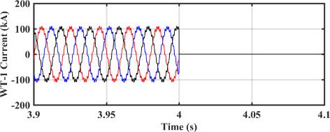
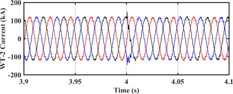
51 (b) Figure 3. 1: The current waveforms of WT-1, WT-2, WT-3, and WT-4, and their FFT analysis, (a) the current waveforms, where WT-1 is disconnected at t = 4 s, (b) FFT analysis of the current waveforms before t = 4 s [98]. However, in Figure 3. 2, WT-4, i.e., the WT with the largest PF, is disconnected from the WPP. Figure 3. 2 shows that the electrical oscillations will be mitigated and damped in the WPP, which confirms that WT-4 is the main source of oscillations, as predicted in Table


52 Figure 3. 2: The currents waveforms of WT-1, WT-2, WT-3, and WT-4, where WT-4 is disconnected at t = 4 s [98]. 48
53 3.4. RESONANCE MODE ANALYSIS PAPER 4 Title: Dynamic resonance sensitivity analysis in wind farms E. Ebrahimzadeh, F. Blaabjerg, X. Wang, and C. L. Bak in Proc. of IEEE PEDG Conference, Brazil, 2017, pp Contributions Performing the sensitivity analysis to identify which bus excites the resonances more Identifying the best candidate bus to do the passive or active passive damping to reduce the resonance problems Results In this part, the electrical resonances of the WPP are identified by the proposed resonance analysis. Figure 3. 3 shows that the WPP has the resonance frequencies at f = 945 Hz, f = 1425 Hz, f = 1705 Hz, and f = 1985 Hz. Figure 3. 3: Resonance analysis of the 400-MW WPP by the proposed method [110]. In order to identify which buses excite the resonances more, the PF analysis has been carried out and the results are shown in Table In this case, as all parameters of the WTs are designed as the same, the structure of the WPP is symmetrical. Therefore, the buses 2 to 5, the buses 6 to 9, and the buses 14 and 15 have the same PF values for different resonances. Table 3. 2 shows that the buses 10 to 13 have the largest PF for the resonance at f = 1705 Hz, the buses 2 to 5 have the smallest PF for the resonance at f = 1705 Hz. For the resonance at f = 1425 Hz, the bus 1 has a much 49
 of the WPP buses for the electrical resonances, which have been identified in Figure 3.")
54 larger PF (PF= 0.945) than the other buses, which confirms that this bus amplifies considerably the disturbances around f = 1425 Hz. Table 3. 2: Participation Factors (PFs) of the WPP buses for the electrical resonances, which have been identified in Figure In order to validate these frequency-domain analysis, the WPP is simulated in the PSCAD software and the results are shown in Figure In this scenario, the main gird voltage has 3% disturbance at f = 1705 Hz. The voltage waveforms of the buses 10, 6, 1, and 2, and their FFT are shown in Figure The voltage of bus 10 has the largest THD and the voltage of the bus 2 has the smallest THD, as expected from Table
55 (a) 51
56 (b) Figure 3. 4: The voltage waveforms for the buses 10, 6, 1, and 2 and their FFT analysis, where the grid voltage has 3% harmonics at f = 1705 Hz, (a) the voltage waveforms, (b) FFT analysis of the voltage waveforms [110]. 52
57 CHAPTER 4. OPTIMIZATION AND MITIGATION 4.1. ABSTRACT In order to damp and mitigate the oscillations and resonances, this chapter discusses an optimization procedure to redesign the controller parameters of WTs. The optimization is done in the frequency domain, where the objective is to put the oscillatory modes of the WPP in the suitable locations with acceptable damping. The proposed design enhances the stability margin and improves the dynamic response of the WPP. Time-domain simulations in the PSCAD software confirm the effectiveness of the presented algorithm PROPOSED METHOD FOR DESIGN As it already discussed, the frequency (f i) and the damping (ζ i) of the oscillatory modes can be identified by i i f i i i i (4.1) If the mode with the largest real part, P c, has a negative real part, the system is stable as the real part of all other poles are smaller and more negative. p j Max(,,, ) c c c c 1 2 q (4.2) Therefore, in order to stabilize the WPP, the constraint H(x) in the optimization procedure is defined in (10) to make sure that all real parts are negative. In order to have a margin, it has been tried that the real parts are smaller than H( x) 0 c (4.3) The vector x is a vector of the optimization variables including the parameters of the power converters: x [ K, K, L, C ] pk ik f k f k (4.4) The dynamic response of a second-order system with different damping ratios has 53
58 been shown in Figure As it can be seen, a system with the smaller damping reaches to its final value faster but oscillates a lot around this value. A system with a larger damping reaches to the final value slower and smoother. Figure 4. 1 shows that the best trade-off between the speed and oscillations happens for damping around 0.8. Figure 4. 1: Dynamic response of a second-order system for different dampings. In a WPP, low-frequency and high-frequency oscillations correspond to the gridconnected converters and passive components, respectively [110]- [113]. Therefore, in order to guarantee the dynamic response of WTs in the WPP, an objective function is defined to set all low-frequency modes with damping around 0.8. The objective function is actually to minimize F(x), which defined as F( x) Max 0.8, 0.8,, j j, f f 500 Hz, j 1, 2,..., n j j h j j n (4.5) In the following sections, more details of the optimum design procedure are discussed in order to mitigate the oscillations and to reduce the resonances OSCILLATIONS MITIGATION PAPER 5 Title: Optimum design of power converter current controllers in power electronics based power systems E. Ebrahimzadeh, F. Blaabjerg, X. Wang, and C. L. Bak, submitted to IEEE Transactions on Industry Applications. 54
59 Contributions Showing that a good design of the WTs under strong grid conditions cannot guarantee stable operation of whole WPP Damping the oscillations by a multi-objective optimization procedure to redesign the parameters of the WT controllers Results Figure 4. 2 shows the mode damping ratios of the individual WT and the WPP for the stand-alone design (initial design). The damping ratios of the modes of the WPP for the optimized parameters (Kp = 9.51e-3, Ki = 4.16, and fres = 357 Hz) are also shown in Figure As it can be seen, the damping ratios of the individual WT for the standalone design is around 0.8, which confirms that the individual WT for a strong grid has a good stability margin and an acceptable dynamic response. However, when all WTs are connected to the WPP, the damping ratios for low-frequency modes are too small and the damping ratio for the frequency around 900 Hz is negative, which shows that the WPP is unstable around this frequency. Therefore, it is necessary to redesign the controller parameters to improve the stability margin and to guarantee a desired dynamic response. As shown in Figure 4. 2, after setting the GSC parameters based on the proposed optimum design procedure, all modes have positive damping, which confirms that the WPP has a stable operation. In addition, the low-frequency modes, which is related to the power converter dynamics, have suitable dampings around 0.8, which depicts that the WPP has a desired dynamic performance for the optimum design. Figure 4. 2: Mode damping ratios of the individual WT and the WPP for the stand-alone design, and for the optimum design. In Figure 4. 3, the WPP is simulated in the time-domain using PSCAD software, where the current controller parameters of the GSCs have been set by the proposed optimum design (before t = 0.5 s). At t = 0.4 s, the current reference is changed from 0.25 p.u. to 1 p.u. As it can be seen, the WPP has a good dynamic response and a stable operation for the optimized parameters. At t = 0.5, the GSC parameters are changed from the optimum design to the initial design. As shown in Figure 4.3, some 55

60 oscillations around 900 Hz propagate into the WPP, because of the instability problems as predicted in Figure 4. 2 in the frequency-domain. Figure 4. 3: Testing the dynamic response of the GSCs; the GSCs parameters are changed from the optimum design to the initial design at t = 0.5 s and the dynamic response of the optimum design is also tested at t = 0.4 s ROBUSTNESS OF THE OPTIMUM DESIGN PAPER 6 Title: Reducing harmonic instability and resonance problems in PMSG based wind farms E. Ebrahimzadeh, F. Blaabjerg, X. Wang, and C. L. Bak, Journal of Emerging and Selected Topics in Power Electronics, vol. 6, no. 1, pp , Mar Contributions Minimizing the number of the resonances by a Genetic Algorithm (GA) 56
Harmonic Stability in Renewable Energy Systems: An Overview
 Harmonic Stability in Renewable Energy Systems: An Overview Frede Blaabjerg and Xiongfei Wang Department of Energy Technology Aalborg University, Denmark fbl@et.aau.dk, xwa@et.aau.dk Outline Introduction
Published in: Proceedings of the IEEE International Power Electronics and Application Conference and Exposition (IEEE PEAC'14)
") Aalborg Universitet Harmonic Stability Assessment for Multi-Paralleled, Grid-Connected Inverters oon, Changwoo; Wang, Xiongfei; Silva, Filipe Miguel Faria da; Bak, Claus Leth; Blaabjerg, Frede Published
Aalborg Universitet Harmonic Stability Assessment for Multi-Paralleled, Grid-Connected Inverters oon, Changwoo; Wang, Xiongfei; Silva, Filipe Miguel Faria da; Bak, Claus Leth; Blaabjerg, Frede Published
Published in: Proceedings of the 2016 IEEE International Conference on Power Electronics, Drives and Energy Systems (PEDES)
") Aalborg Universitet Voltage Feedback based Harmonic Compensation for an Offshore Wind Power Plant Chaudhary, Sanjay K.; Lascu, Cristian Vaslie; Teodorescu, Remus; Kocewiak, ukasz Published in: Proceedings
Aalborg Universitet Voltage Feedback based Harmonic Compensation for an Offshore Wind Power Plant Chaudhary, Sanjay K.; Lascu, Cristian Vaslie; Teodorescu, Remus; Kocewiak, ukasz Published in: Proceedings
Resonances in Collection Grids of Offshore Wind Farms
 Downloaded from orbit.dtu.dk on: Dec 20, 2017 Resonances in Collection Grids of Offshore Wind Farms Holdyk, Andrzej Publication date: 2013 Link back to DTU Orbit Citation (APA): Holdyk, A. (2013). Resonances
Damping and Harmonic Control of DG Interfacing. Power Converters
 University of Alberta Damping and Harmonic Control of DG Interfacing Power Converters by Jinwei He A thesis submitted to the Faculty of Graduate Studies and Research in partial fulfillment of the requirements
MODELING AND ANALYSIS OF IMPEDANCE NETWORK VOLTAGE SOURCE CONVERTER FED TO INDUSTRIAL DRIVES
 Int. J. Engg. Res. & Sci. & Tech. 2015 xxxxxxxxxxxxxxxxxxxxxxxx, 2015 Research Paper MODELING AND ANALYSIS OF IMPEDANCE NETWORK VOLTAGE SOURCE CONVERTER FED TO INDUSTRIAL DRIVES N Lakshmipriya 1* and L
Published in: Proceedings of the 37th Annual Conference of IEEE Industrial Electronics Society, IECON 2011
 Aalborg Universitet A centralized control architecture for harmonic voltage suppression in islanded microgrids Wang, Xiongfei; Blaabjerg, Frede; Chen, Zhe; Guerrero, Josep M. Published in: Proceedings
Published in: Proceedings of the 30th Annual IEEE Applied Power Electronics Conference and Exposition, APEC 2015
 Aalborg Universitet Stabilization of Multiple Unstable Modes for Small-Scale Inverter-Based Power Systems with Impedance-Based Stability Analysis oon, Changwoo; Wang, Xiongfei; Bak, Claus Leth; Blaabjerg,
System grounding of wind farm medium voltage cable grids
 Downloaded from orbit.dtu.dk on: Apr 23, 2018 System grounding of wind farm medium voltage cable grids Hansen, Peter; Østergaard, Jacob; Christiansen, Jan S. Published in: NWPC 2007 Publication date: 2007
Aalborg Universitet. Design and Control of A DC Grid for Offshore Wind Farms Deng, Fujin. Publication date: 2012
 Aalborg Universitet Design and Control of A DC Grid for Offshore Wind Farms Deng, Fujin Publication date: 2012 Document Version Publisher's PDF, also known as Version of record Link to publication from
Power Conditioning Equipment for Improvement of Power Quality in Distribution Systems M. Weinhold R. Zurowski T. Mangold L. Voss
 Power Conditioning Equipment for Improvement of Power Quality in Distribution Systems M. Weinhold R. Zurowski T. Mangold L. Voss Siemens AG, EV NP3 P.O. Box 3220 91050 Erlangen, Germany e-mail: Michael.Weinhold@erls04.siemens.de
Harmonics Reduction in a Wind Energy Conversion System with a Permanent Magnet Synchronous Generator
 International Journal of Data Science and Analysis 2017; 3(6): 58-68 http://www.sciencepublishinggroup.com/j/ijdsa doi: 10.11648/j.ijdsa.20170306.11 ISSN: 2575-1883 (Print); ISSN: 2575-1891 (Online) Conference
Published in: IECON 2016: The 42nd Annual Conference of IEEE Industrial Electronics Society
 Downloaded from vbn.aau.dk on: marts 11, 219 Aalborg Universitet Harmonic Damping in DG-Penetrated Distribution Network Lu, Jinghang; Savaghebi, Mehdi; Guerrero, Josep M. Published in: IECON 216: The 42nd
Distance Protection of Cross-Bonded Transmission Cable-Systems
 Downloaded from vbn.aau.dk on: April 19, 2019 Aalborg Universitet Distance Protection of Cross-Bonded Transmission Cable-Systems Bak, Claus Leth; F. Jensen, Christian Published in: Proceedings of the 12th
Wind Power Plant Voltage Control Optimization with Embedded Application of Wind Turbines and Statcom
 Downloaded from orbit.dtu.dk on: Aug 3, 018 Wind Power Plant Voltage Control Optimization with Embedded Application of Wind Turbines and Statcom Wu, Qiuwei; Solanas, Jose Ignacio Busca; Zhao, Haoran; Kocewiak,
Stability Enhancement for Transmission Lines using Static Synchronous Series Compensator
 Stability Enhancement for Transmission Lines using Static Synchronous Series Compensator Ishwar Lal Yadav Department of Electrical Engineering Rungta College of Engineering and Technology Bhilai, India
p. 1 p. 6 p. 22 p. 46 p. 58
 Comparing power factor and displacement power factor corrections based on IEEE Std. 18-2002 Harmonic problems produced from the use of adjustable speed drives in industrial plants : case study Theory for
A Dynamic Consensus Algorithm based Low-Voltage Ride-Through Operation of Power Converters in Grid-Interactive Microgrids
 Aalborg Universitet A Dynamic Consensus Algorithm based Low-Voltage Ride-Through Operation of Power Converters in Grid-Interactive Microgrids Zhao, Xin; Meng, Lexuan; Savaghebi, Mehdi; Quintero, Juan Carlos
Measurements of the Distorted No-load Current of a 60/20 kv, 6 MVA Power Transformer Søgaard, Kim; Bak, Claus Leth; Wiechowski, Wojciech Tomasz
 Aalborg Universitet Measurements of the Distorted No-load Current of a 60/20 kv, 6 MVA Power Transformer Søgaard, Kim; Bak, Claus Leth; Wiechowski, Wojciech Tomasz Publication date: 2005 Document Version
Design and Development of MPPT for Wind Electrical Power System under Variable Speed Generation Using Fuzzy Logic
 Design and Development of MPPT for Wind Electrical Power System under Variable Speed Generation Using Fuzzy Logic J.Pavalam 1, R.Ramesh Kumar 2, Prof. K.Umadevi 3 PG scholar-me (PED), Excel College of
Study of High Voltage AC Underground Cable Systems Silva, Filipe Miguel Faria da; Bak, Claus Leth; Wiechowski, Wojciech T.
 Aalborg Universitet Study of High Voltage AC Underground Cable Systems Silva, Filipe Miguel Faria da; Bak, Claus Leth; Wiechowski, Wojciech T. Published in: Proceedings of the Danish PhD Seminar on Detailed
A Voltage Controlled DSTATCOM using Hybrid Renewable Energy DC Link VSI for Power Quality Improvement
 IJIRST International Journal for Innovative Research in Science & Technology Volume 3 Issue 04 September 2016 ISSN (online): 2349-6010 A Voltage Controlled DSTATCOM using Hybrid Renewable Energy DC Link
Grid codes and wind farm interconnections CNY Engineering Expo. Syracuse, NY November 13, 2017
 Grid codes and wind farm interconnections CNY Engineering Expo Syracuse, NY November 13, 2017 Purposes of grid codes Grid codes are designed to ensure stable operating conditions and to coordinate the
Power Quality enhancement of a distribution line with DSTATCOM
 ower Quality enhancement of a distribution line with DSTATCOM Divya arashar 1 Department of Electrical Engineering BSACET Mathura INDIA Aseem Chandel 2 SMIEEE,Deepak arashar 3 Department of Electrical
[Mahagaonkar*, 4.(8): August, 2015] ISSN: (I2OR), Publication Impact Factor: 3.785
![[Mahagaonkar*, 4.(8): August, 2015] ISSN: (I2OR), Publication Impact Factor: 3.785](/thumbs/79/80126240.jpg "[Mahagaonkar*, 4.(8): August, 2015] ISSN: (I2OR), Publication Impact Factor: 3.785") IJESRT INTERNATIONAL JOURNAL OF ENGINEERING SCIENCES & RESEARCH TECHNOLOGY POWER QUALITY IMPROVEMENT OF GRID CONNECTED WIND ENERGY SYSTEM BY USING STATCOM Mr.Mukund S. Mahagaonkar*, Prof.D.S.Chavan * M.Tech
IJESRT INTERNATIONAL JOURNAL OF ENGINEERING SCIENCES & RESEARCH TECHNOLOGY POWER QUALITY IMPROVEMENT OF GRID CONNECTED WIND ENERGY SYSTEM BY USING STATCOM Mr.Mukund S. Mahagaonkar*, Prof.D.S.Chavan * M.Tech
MITIGATION OF VOLTAGE SAGS/SWELLS USING DYNAMIC VOLTAGE RESTORER (DVR)
") VOL. 4, NO. 4, JUNE 9 ISSN 89-668 6-9 Asian Research Publishing Network (ARPN). All rights reserved. MITIGATION OF VOLTAGE SAGS/SWELLS USING DYNAMIC VOLTAGE RESTORER (DVR) Rosli Omar and Nasrudin Abd Rahim
VOL. 4, NO. 4, JUNE 9 ISSN 89-668 6-9 Asian Research Publishing Network (ARPN). All rights reserved. MITIGATION OF VOLTAGE SAGS/SWELLS USING DYNAMIC VOLTAGE RESTORER (DVR) Rosli Omar and Nasrudin Abd Rahim
B.Tech Academic Projects EEE (Simulation)
") B.Tech Academic Projects EEE (Simulation) Head office: 2 nd floor, Solitaire plaza, beside Image Hospital, Ameerpet Ameerpet : 040-44433434, email id : info@kresttechnology.com Dilsukhnagar : 9000404181,
B.Tech Academic Projects EEE (Simulation) Head office: 2 nd floor, Solitaire plaza, beside Image Hospital, Ameerpet Ameerpet : 040-44433434, email id : info@kresttechnology.com Dilsukhnagar : 9000404181,
ISSN: ISO 9001:2008 Certified International Journal of Engineering Science and Innovative Technology (IJESIT) Volume 2, Issue 3, May 2013
 Volume 2, Issue 3, May 2013") A Statcom-Control Scheme for Power Quality Improvement of Grid Connected Wind Energy System B.T.RAMAKRISHNARAO*, B.ESWARARAO**, L.NARENDRA**, K.PRAVALLIKA** * Associate.Professor, Dept.of EEE, Lendi Inst.Of
A Statcom-Control Scheme for Power Quality Improvement of Grid Connected Wind Energy System B.T.RAMAKRISHNARAO*, B.ESWARARAO**, L.NARENDRA**, K.PRAVALLIKA** * Associate.Professor, Dept.of EEE, Lendi Inst.Of
Simulation of Dc-Link Power Converter for Integrating Offshore Wind Turbine Generator to Grid
 Simulation of Dc-Link Power Converter for Integrating Offshore Wind Turbine Generator to Grid Chaitanya Krishna Jambotkar #1, Prof. Uttam S Satpute #2 #1Department of Electronics and Communication Engineering,
Published in: Proceedings of the 16th Annual IEEE Workshop on Control and Modeling for Power Electronics, COMPEL 2015
 Aalborg Universitet Modeling and Simulation of DC Power Electronics Systems Using Harmonic State Space (HSS) Method Kwon, Jun Bum; Wang, Xiongfei; Bak, Claus Leth; Blaabjerg, Frede Published in: Proceedings
Aalborg Universitet. Suppression of synchronous resonance for VSGs Yang, Dongsheng; Wu, Heng; Wang, Xiongfei; Blaabjerg, Frede
 Aalborg Universitet Suppression of synchronous resonance for VSGs Yang, Dongsheng; Wu, Heng; Wang, Xiongfei; Blaabjerg, Frede Published in: The Journal of Engineering DOI (link to publication from Publisher):
Power Quality Improvement of Unified Power Quality Conditioner Using Reference Signal Generation Method
 Vol.2, Issue.3, May-June 2012 pp-682-686 ISSN: 2249-6645 Power Quality Improvement of Unified Power Quality Conditioner Using Reference Signal Generation Method C. Prakash 1, N. Suparna 2 1 PG Scholar,
ELEMENTS OF FACTS CONTROLLERS
 1 ELEMENTS OF FACTS CONTROLLERS Rajiv K. Varma Associate Professor Hydro One Chair in Power Systems Engineering University of Western Ontario London, ON, CANADA rkvarma@uwo.ca POWER SYSTEMS - Where are
CHAPTER 5 DESIGN OF DSTATCOM CONTROLLER FOR COMPENSATING UNBALANCES
 86 CHAPTER 5 DESIGN OF DSTATCOM CONTROLLER FOR COMPENSATING UNBALANCES 5.1 INTRODUCTION Distribution systems face severe power quality problems like current unbalance, current harmonics, and voltage unbalance,
Investigation of D-Statcom Operation in Electric Distribution System
 J. Basic. Appl. Sci. Res., (2)29-297, 2 2, TextRoad Publication ISSN 29-434 Journal of Basic and Applied Scientific Research www.textroad.com Investigation of D-Statcom Operation in Electric Distribution
NOWADAYS, there is much interest in connecting various
 IEEE TRANSACTIONS ON SMART GRID, VOL. 4, NO. 1, MARCH 2013 419 Modified Dynamic Phasor Estimation Algorithm for the Transient Signals of Distributed Generators Dong-Gyu Lee, Sang-Hee Kang, and Soon-Ryul
Mission profile resolution effects on lifetime estimation of doubly-fed induction generator power converter
 Aalborg Universitet Mission profile resolution effects on lifetime estimation of doubly-fed induction generator power converter Zhang, Guanguan; Zhou, Dao; Blaabjerg, Frede; Yang, Jian Published in: Proceedings
Islanding Detection and Frequency Circuit Measurement by Power Distribution Relation Depending on the Angle
 215 International Journal of Smart Electrical Engineering, Vol.5, No.4, Fall 2016 ISSN: 2251-9246 pp. 215:220 Islanding Detection and Frequency Circuit Measurement by Power Distribution Relation Depending
INVESTIGATION OF HARMONIC DETECTION TECHNIQUES FOR SHUNT ACTIVE POWER FILTER
 IOSR Journal of Electronics & Communication Engineering (IOSR-JECE) ISSN(e) : 2278-1684 ISSN(p) : 2320-334X, PP 68-73 www.iosrjournals.org INVESTIGATION OF HARMONIC DETECTION TECHNIQUES FOR SHUNT ACTIVE
DRIVE FRONT END HARMONIC COMPENSATOR BASED ON ACTIVE RECTIFIER WITH LCL FILTER
 DRIVE FRONT END HARMONIC COMPENSATOR BASED ON ACTIVE RECTIFIER WITH LCL FILTER P. SWEETY JOSE JOVITHA JEROME Dept. of Electrical and Electronics Engineering PSG College of Technology, Coimbatore, India.
Harnessing of wind power in the present era system
 International Journal of Scientific & Engineering Research Volume 3, Issue 1, January-2012 1 Harnessing of wind power in the present era system Raghunadha Sastry R, Deepthy N Abstract This paper deals
ISSUES OF SYSTEM AND CONTROL INTERACTIONS IN ELECTRIC POWER SYSTEMS
 ISSUES OF SYSTEM AND CONTROL INTERACTIONS IN ELECTRIC POWER SYSTEMS INDO-US Workshop October 2009, I.I.T. Kanpur INTRODUCTION Electric Power Systems are very large, spread over a wide geographical area
Improved Transient Compensation Using PI-SRF Control Scheme Based UHVDC For Offshore Wind Power Plant
 Improved Transient Compensation Using PI-SRF Control Scheme Based UHVDC For Offshore Wind Power Plant Sangeetha M 1, Arivoli R 2, Karthikeyan B 3 1 Assistant Professor, Department of EEE, Imayam College
Synchronization and Smooth Connection of Solar Photovoltaic Generation to Utility Grid
 International Journal of Electrical Engineering. ISSN 0974-2158 Volume 9, Number 1 (2016), pp. 51-56 International Research Publication House http://www.irphouse.com Synchronization and Smooth Connection
Arvind Pahade and Nitin Saxena Department of Electrical Engineering, Jabalpur Engineering College, Jabalpur, (MP), India
, India") e t International Journal on Emerging Technologies 4(1): 10-16(2013) ISSN No. (Print) : 0975-8364 ISSN No. (Online) : 2249-3255 Control of Synchronous Generator Excitation and Rotor Angle Stability by
e t International Journal on Emerging Technologies 4(1): 10-16(2013) ISSN No. (Print) : 0975-8364 ISSN No. (Online) : 2249-3255 Control of Synchronous Generator Excitation and Rotor Angle Stability by
Cascaded H-Bridge Five Level Inverter for Harmonics Mitigation and Reactive Power Control
 Cascaded H-Bridge Five Level Inverter for Harmonics Mitigation and Reactive Power Control Prof. D.S.Chavan 1, Mukund S.Mahagaonkar 2 Assistant professor, Dept. of ELE, BVCOE, Pune, Maharashtra, India 1
LOW VOLTAGE RIDE - THROUGH CAPABILITY OF WIND FARMS
 Scientific Journal Impact Factor (SJIF): 1.711 e-issn: 2349-9745 p-issn: 2393-8161 International Journal of Modern Trends in Engineering and Research www.ijmter.com LOW VOLTAGE RIDE - THROUGH CAPABILITY
Auxiliary DC Voltage
 THE 9 th INTERNATIONAL SYMPOSIUM ON ADVANCED TOPICS IN ELECTRICAL ENGINEERING May 7-9, 2015 Bucharest, Romania DVR with Auxiliary DC Voltage Source Provided by A High Power Diode Based Rectifier Used in
Analysis of Effect on Transient Stability of Interconnected Power System by Introduction of HVDC Link.
 Analysis of Effect on Transient Stability of Interconnected Power System by Introduction of HVDC Link. Mr.S.B.Dandawate*, Mrs.S.L.Shaikh** *,**(Department of Electrical Engineering, Walchand College of
Improvement of Electricity Distribution Services Using a DVR with a Constant DC Voltage Source Instaled in MV Connection Substations
 Improvement of Electricity Distribution Services Using a DVR with a Constant DC Voltage Source Instaled in MV Connection Substations Gheorghe Ioan Nicolaescu, Horia Andrei, Stefan Radulescu Electrical
Authors and affiliations. Introduction. Approach
 Abstract title Provision of primary frequency support and inertia emulation by offshore wind farms connected through multi-terminal VSC-HVDC links. Authors and affiliations Sotirios Nanou *, Argiris Spetsiotis,
Distributed Coordination and Control of Renewable Energy Sources in Microgrids
 University of South Florida Scholar Commons Graduate Theses and Dissertations Graduate School 6-14-2016 Distributed Coordination and Control of Renewable Energy Sources in Microgrids Javad Khazaei Khazaei
Three Phase PFC and Harmonic Mitigation Using Buck Boost Converter Topology
 Three Phase PFC and Harmonic Mitigation Using Buck Boost Converter Topology Riya Philip 1, Reshmi V 2 Department of Electrical and Electronics, Amal Jyothi College of Engineering, Koovapally, India 1,
Impedance analysis of harmonic resonance in HVDC connected Wind Power Plants
 Master Thesis Project Impedance analysis of harmonic resonance in HVDC connected Wind Power Plants Author: Advisors: Call: July 2016 Igor Sowa Dr. José Luis Domínguez Dr. Oriol Gomis Escola Tècnica Superior
Transient stability improvement by using shunt FACT device (STATCOM) with Reference Voltage Compensation (RVC) control scheme
 with Reference Voltage Compensation (RVC) control scheme") I J E E E C International Journal of Electrical, Electronics ISSN No. (Online) : 2277-2626 and Computer Engineering 2(1): 7-12(2013) Transient stability improvement by using shunt FACT device (STATCOM)
I J E E E C International Journal of Electrical, Electronics ISSN No. (Online) : 2277-2626 and Computer Engineering 2(1): 7-12(2013) Transient stability improvement by using shunt FACT device (STATCOM)
Published in: Proceedings of the 2014 IEEE Energy Conversion Congress and Exposition (ECCE)
") Aalborg Universitet Proportional derivative based stabilizing control of paralleled grid converters with cables in renewable power plants Wang, Xiongfei; Blaabjerg, Frede; Loh, Poh Chiang Published in:
Aalborg Universitet Proportional derivative based stabilizing control of paralleled grid converters with cables in renewable power plants Wang, Xiongfei; Blaabjerg, Frede; Loh, Poh Chiang Published in:
Simulation and Comparison of DVR and DSTATCOM Used For Voltage Sag Mitigation at Distribution Side
 Simulation and Comparison of DVR and DSTATCOM Used For Voltage Sag Mitigation at Distribution Side 1 Jaykant Vishwakarma, 2 Dr. Arvind Kumar Sharma 1 PG Student, High voltage and Power system, Jabalpur
Resonant Controller to Minimize THD for PWM Inverter
 IOSR Journal of Electrical and Electronics Engineering (IOSR-JEEE) e-issn: 2278-1676,p-ISSN: 2320-3331, Volume 10, Issue 3 Ver. III (May Jun. 2015), PP 49-53 www.iosrjournals.org Resonant Controller to
Protection from Voltage Sags and Swells by Using FACTS Controller
 Protection from Voltage Sags and Swells by Using FACTS Controller M.R.Mohanraj 1, V.P.Suresh 2, G.Syed Zabiyullah 3 Assistant Professor, Department of Electrical and Electronics Engineering, Excel College
Adaptive ANN based STATCOM and DVR for optimal integration of wind energy with grid using permanent magnet synchronous generator
 Adaptive ANN based STATCOM and DVR for optimal integration of wind energy with grid using permanent magnet synchronous generator Priyanka Sahu Columbia Institute of Engineering and Technology, Raipur,
Published in: Proceedings of the 27th Annual IEEE Applied Power Electronics Conference and Exposition
 Aalborg Universitet Synthesis of variable harmonic impedance in inverter-interfaced distributed generation unit for harmonic damping throughout a distribution network Wang, Xiongfei; Blåbjerg, Frede; Chen,
Published in: Proccedings of the th Annual IEEE Applied Power Electronics Conference and Exposition (APEC)
") Aalborg Universitet Power Flow Analysis Algorithm for Islanded LV Microgrids Including Distributed Generator Units with Droop Control and Virtual Impedance Loop Li, Chendan; Chaudhary, Sanjay K.; Quintero,
Aalborg Universitet Power Flow Analysis Algorithm for Islanded LV Microgrids Including Distributed Generator Units with Droop Control and Virtual Impedance Loop Li, Chendan; Chaudhary, Sanjay K.; Quintero,
Published in: Proceedings of the 39th Annual Conference of IEEE Industrial Electronics Society, IECON 2013
 Aalborg Universitet Selective virtual capacitive impedance loop for harmonics voltage compensation in islanded microgrids Micallef, Alexander; Apap, Maurice; Spiteri-Staines, Cyril; Guerrero, Josep M.
IJCSIET--International Journal of Computer Science information and Engg., Technologies ISSN
 A novel control strategy for Mitigation of Inrush currents in Load Transformers using Series Voltage source Converter Pulijala Pandu Ranga Rao *1, VenuGopal Reddy Bodha *2 #1 PG student, Power Electronics
Multilevel Inverter Based Statcom For Power System Load Balancing System
 IOSR Journal of Electronics and Communication Engineering (IOSR-JECE) e-issn: 2278-2834,p- ISSN: 2278-8735 PP 36-43 www.iosrjournals.org Multilevel Inverter Based Statcom For Power System Load Balancing
Mitigation of voltage disturbances (Sag/Swell) utilizing dynamic voltage restorer (DVR)
 utilizing dynamic voltage restorer (DVR)") Research Journal of Engineering Sciences ISSN 2278 9472 Mitigation of voltage disturbances (Sag/Swell) utilizing dynamic voltage restorer (DVR) Abstract Srishti Verma * and Anupama Huddar Electrical Engineering
Research Journal of Engineering Sciences ISSN 2278 9472 Mitigation of voltage disturbances (Sag/Swell) utilizing dynamic voltage restorer (DVR) Abstract Srishti Verma * and Anupama Huddar Electrical Engineering
Active Elimination of Low-Frequency Harmonics of Traction Current-Source Active Rectifier
 Transactions on Electrical Engineering, Vol. 1 (2012), No. 1 30 Active Elimination of Low-Frequency Harmonics of Traction Current-Source Active Rectifier Jan Michalík1), Jan Molnár2) and Zdeněk Peroutka2)
Design of SVPWM Based Inverter for Mitigation of Harmonics in Power System
 Design of SVPWM Based Inverter for Mitigation of Harmonics in Power System 1 Leena N C, 2 B. Rajesh Kamath, 3 Shri Harsha 1,2,3 Department of EEE, Sri Siddhartha Institute of Technology, Tumkur-572105,
Enhancement of Power Quality Using Advanced Series Active Power Filters
 Enhancement of Power Quality Using Advanced Series Active Power Filters Manoj siva kumar 1, P.Rayalakshmi 2 Associate Professor, Dept. of EEE, PBRVITS, Kavali, SPSR Nellore, A.P, India 1 M.Tech Student,
Voltage Sag and Swell Mitigation Using Dynamic Voltage Restore (DVR)
") Voltage Sag and Swell Mitigation Using Dynamic Voltage Restore (DVR) Mr. A. S. Patil Mr. S. K. Patil Department of Electrical Engg. Department of Electrical Engg. I. C. R. E. Gargoti I. C. R. E. Gargoti
Voltage Sag and Swell Mitigation Using Dynamic Voltage Restore (DVR) Mr. A. S. Patil Mr. S. K. Patil Department of Electrical Engg. Department of Electrical Engg. I. C. R. E. Gargoti I. C. R. E. Gargoti
Chapter -3 ANALYSIS OF HVDC SYSTEM MODEL. Basically the HVDC transmission consists in the basic case of two
 Chapter -3 ANALYSIS OF HVDC SYSTEM MODEL Basically the HVDC transmission consists in the basic case of two convertor stations which are connected to each other by a transmission link consisting of an overhead
Analysis, Modeling and Simulation of Dynamic Voltage Restorer (DVR)for Compensation of Voltage for sag-swell Disturbances
for Compensation of Voltage for sag-swell Disturbances") IOSR Journal of Electrical and Electronics Engineering (IOSR-JEEE) e-issn: 2278-1676,p-ISSN: 2320-3331, Volume 9, Issue 3 Ver. I (May Jun. 2014), PP 36-41 Analysis, Modeling and Simulation of Dynamic Voltage
IOSR Journal of Electrical and Electronics Engineering (IOSR-JEEE) e-issn: 2278-1676,p-ISSN: 2320-3331, Volume 9, Issue 3 Ver. I (May Jun. 2014), PP 36-41 Analysis, Modeling and Simulation of Dynamic Voltage
Published in: Proceedings of 2016 IEEE 8th International Power Electronics and Motion Control Conference, IPEMC-ECCE Asia 2016
 Aalborg Universitet Control architecture for paralleled current-source-inverter (CSI) based uninterruptible power systems (UPS) Wei, Baoze; Quintero, Juan Carlos Vasquez; Guerrero, Josep M.; Guo, Xiaoqiang
Extraction of Extreme Power and Standardize of Voltage and Frequency under Varying Wind Conditions
 Extraction of Extreme Power and Standardize of Voltage and Frequency under Varying Wind Conditions V. Karthikeyan 1 1 Department of ECE, SVSCE, Coimbatore, Tamilnadu, India, Karthick77keyan@gmail.com `
CHAPTER 5 POWER QUALITY IMPROVEMENT BY USING POWER ACTIVE FILTERS
 86 CHAPTER 5 POWER QUALITY IMPROVEMENT BY USING POWER ACTIVE FILTERS 5.1 POWER QUALITY IMPROVEMENT This chapter deals with the harmonic elimination in Power System by adopting various methods. Due to the
Control of grid connected inverter system for sinusoidal current injection with improved performance
 Control of grid connected inverter system for sinusoidal current injection with improved performance Simeen. S. Mujawar. Electrical engineering Department, Pune University /PVG s COET, Pune, India. simeen1990@gmail.com
Z-SOURCE INVERTER BASED DVR FOR VOLTAGE SAG/SWELL MITIGATION
 Z-SOURCE INVERTER BASED DVR FOR VOLTAGE SAG/SWELL MITIGATION 1 Arsha.S.Chandran, 2 Priya Lenin 1 PG Scholar, 2 Assistant Professor 1 Electrical & Electronics Engineering 1 Mohandas College of Engineering
Enhancement of Power Quality in Distribution System Using D-Statcom for Different Faults
 Enhancement of Power Quality in Distribution System Using D-Statcom for Different s Dr. B. Sure Kumar 1, B. Shravanya 2 1 Assistant Professor, CBIT, HYD 2 M.E (P.S & P.E), CBIT, HYD Abstract: The main
WILEY CONTROL OF POWER INVERTERS IN RENEWABLE ENERGY AND SMART GRID INTEGRATION. Qing-Chang Zhong. Tomas Hornik IEEE PRESS
 CONTROL OF POWER INVERTERS IN RENEWABLE ENERGY AND SMART GRID INTEGRATION Qing-Chang Zhong The University of Sheffield, UK Tomas Hornik Turbo Power Systems Ltd., UK WILEY A John Wiley & Sons, Ltd., Publication
Control of a Three Phase Inverter Mimicking Synchronous Machine with Fault Ridethrough
 2017 Ninth Annual IEEE Green Technologies Conference Control of a Three Phase Inverter Mimicking Synchronous Machine with Fault Ridethrough Capability Vikram Roy Chowdhury, Subhajyoti Mukherjee, Pourya
Control of Power Converters for Distributed Generation
 Mechatronics Industrial Advisory Board 2004 Control of Power Converters for Distributed Generation Ph.D. Student: Min Dai Advisor: Prof. Ali Keyhani Department of Electrical and Computer Engineering The
Wind Power Plant Transmission System Modelling for Harmonic Propagation and Small-signal Stability Analysis
 Wind Power Plant Transmission System Modelling for Harmonic Propagation and Small-signal Stability Analysis Łukasz Hubert Kocewiak 1 Electrical Systems DONG Energy Wind Power A/S Gentofte, Denmark 1 Bjørn
DC-GRID PHYSICAL MODELING PLATFORM DESIGN AND SIMULATION*
 -GRID PHYSICAL MODELING PLATFORM DESIGN AND SIMLATION* Minxiao Han 1, Xiaoling Su** 1, Xiao Chen 1, Wenli Yan 1, Zhengkui Zhao 1 State Key Laboratory of Alternate Electrical Power System with Renewable
ISSN Vol.04,Issue.08, July-2016, Pages:
 WWW.IJITECH.ORG ISSN 2321-8665 Vol.04,Issue.08, July-2016, Pages:1335-1341 A Voltage Controlled D-STATCOM Used In Three Phase Four Wire System for Power Quality Improvement J.RAGHAVENDRA 1, C.SREENIVASULU
Design and Simulation of DVR Used For Voltage Sag Mitigation at Distribution Side
 Design and Simulation of DVR Used For Voltage Sag Mitigation at Distribution Side Jaykant Vishwakarma 1, Dr. Arvind Kumar Sharma 2 1 PG Student, High voltage and Power system, Jabalpur Engineering College,
ISSN: ISO 9001:2008 Certified International Journal of Engineering Science and Innovative Technology (IJESIT) Volume 2, Issue 3, May 2013
 Volume 2, Issue 3, May 2013") Power Quality Enhancement Using Hybrid Active Filter D.Jasmine Susila, R.Rajathy Department of Electrical and electronics Engineering, Pondicherry Engineering College, Pondicherry Abstract This paper presents
Power Quality Enhancement Using Hybrid Active Filter D.Jasmine Susila, R.Rajathy Department of Electrical and electronics Engineering, Pondicherry Engineering College, Pondicherry Abstract This paper presents
A MPPT ALGORITHM BASED PV SYSTEM CONNECTED TO SINGLE PHASE VOLTAGE CONTROLLED GRID
 International Journal of Advancements in Research & Technology, Volume 1, Issue 5, October-2012 1 A MPPT ALGORITHM BASED PV SYSTEM CONNECTED TO SINGLE PHASE VOLTAGE CONTROLLED GRID SREEKANTH G, NARENDER
Harmonic analysis of collection grid in offshore wind installations
 Harmonic analysis of collection grid in offshore wind installations Chan Shan Wind Energy Submission date: August 2016 Supervisor: Ole-Morten Midtgård, IEL Co-supervisor: Salvatore D'Arco, SINTEF Energy
Increasing Dynamic Stability of the Network Using Unified Power Flow Controller (UPFC)
") Increasing Dynamic Stability of the Network Using Unified Power Flow Controller (UPFC) K. Manoz Kumar Reddy (Associate professor, Electrical and Electronics Department, Sriaditya Engineering College, India)
Increasing Dynamic Stability of the Network Using Unified Power Flow Controller (UPFC) K. Manoz Kumar Reddy (Associate professor, Electrical and Electronics Department, Sriaditya Engineering College, India)
Direct Harmonic Analysis of the Voltage Source Converter
 1034 IEEE TRANSACTIONS ON POWER DELIVERY, VOL. 18, NO. 3, JULY 2003 Direct Harmonic Analysis of the Voltage Source Converter Peter W. Lehn, Member, IEEE Abstract An analytic technique is presented for
New Direct Torque Control of DFIG under Balanced and Unbalanced Grid Voltage
 1 New Direct Torque Control of DFIG under Balanced and Unbalanced Grid Voltage B. B. Pimple, V. Y. Vekhande and B. G. Fernandes Department of Electrical Engineering, Indian Institute of Technology Bombay,
CHAPTER 4 PV-UPQC BASED HARMONICS REDUCTION IN POWER DISTRIBUTION SYSTEMS
 66 CHAPTER 4 PV-UPQC BASED HARMONICS REDUCTION IN POWER DISTRIBUTION SYSTEMS INTRODUCTION The use of electronic controllers in the electric power supply system has become very common. These electronic
Dynamic Phasors for Small Signal Stability Analysis
 for Small Signal Stability Analysis Chandana Karawita (Transgrid Solutions) for Small Signal Stability Analysis Outline Introduction 1 Introduction Simulation and Analysis Techniques Typical Outputs Modelling
CHAPTER 4 POWER QUALITY AND VAR COMPENSATION IN DISTRIBUTION SYSTEMS
 84 CHAPTER 4 POWER QUALITY AND VAR COMPENSATION IN DISTRIBUTION SYSTEMS 4.1 INTRODUCTION Now a days, the growth of digital economy implies a widespread use of electronic equipment not only in the industrial
Bhavin Gondaliya 1st Head, Electrical Engineering Department Dr. Subhash Technical Campus, Junagadh, Gujarat (India)
") ISSN: 2349-7637 (Online) RESEARCH HUB International Multidisciplinary Research Journal (RHIMRJ) Research Paper Available online at: www.rhimrj.com Modeling and Simulation of Distribution STATCOM Bhavin
ISSN: 2349-7637 (Online) RESEARCH HUB International Multidisciplinary Research Journal (RHIMRJ) Research Paper Available online at: www.rhimrj.com Modeling and Simulation of Distribution STATCOM Bhavin
ISSN Vol.07,Issue.21, December-2015, Pages:
 ISSN 2348 2370 Vol.07,Issue.21, December-2015, Pages:4128-4132 www.ijatir.org Mitigation of Multi Sag/Swell using DVR with Hysteresis Voltage Control DAKOJU H V V S S N MURTHY 1, V. KAMARAJU 2 1 PG Scholar,
OVERVIEW OF SVC AND STATCOM FOR INSTANTANEOUS POWER CONTROL AND POWER FACTOR IMPROVEMENT
 OVERVIEW OF SVC AND STATCOM FOR INSTANTANEOUS POWER CONTROL AND POWER FACTOR IMPROVEMENT Harshkumar Sharma 1, Gajendra Patel 2 1 PG Scholar, Electrical Department, SPCE, Visnagar, Gujarat, India 2 Assistant
Voltage Sags in Distribution Systems with Induction Motor Loads Fed by Power Converters and Voltage Mitigation using DVR and D-STATCOM
 International Journal of Electrical Engineering. ISSN 0974-2158 Volume 5, Number 7 (2012), pp. 889-902 International Research Publication House http://www.irphouse.com Voltage Sags in Distribution Systems
Modeling of PV Interconnected Distribution System using Simulink
 2018 IJSRST Volume 4 Issue 5 Print ISSN: 2395-6011 Online ISSN: 2395-602X Themed Section: Science and Technology Modeling of PV Interconnected Distribution System using Simulink Pooja A. Bhonge *1, Kawita
A Static Synchronous Compensator for Reactive Power Compensation under Distorted Mains Voltage Conditions
 10 th International Symposium Topical Problems in the Field of Electrical and Power Engineering Pärnu, Estonia, January 10-15, 2011 A Static Synchronous Compensator for Reactive Power Compensation under