UCLA UCLA Electronic Theses and Dissertations
|
|
|
- Lillian Charles
- 5 years ago
- Views:
Transcription
1 UCLA UCLA Electronic Theses and Dissertations Title Substrate Integrated Waveguide Based Metamaterial Components and Novel Miniaturized Planar Antennas Permalink Author Dong, Yuandan Publication Date 2012 Peer reviewed Thesis/dissertation escholarship.org Powered by the California Digital Library University of California
2 UNIVERSITY OF CALIFORNIA Los Angeles Substrate Integrated Waveguide Based Metamaterial Components and Novel Miniaturized Planar Antennas A dissertation submitted in partial satisfaction of the requirements for the degree Doctor of Philosophy in Electrical Engineering by Yuandan Dong 2012
3 Copyright by Yuandan Dong 2012
4 ABSTRACT OF THE DISSERTATION Substrate Integrated Waveguide Based Metamaterial Components and Novel Miniaturized Planar Antennas by Yuandan Dong Doctor of Philosophy in Electrical Engineering University of California, Los Angeles, 2012 Professor Tatsuo Itoh, Chair Miniaturized microwave components have drawn increased attention due to the size shrinking of the modern communication systems. This dissertation proposes two approaches to address this problem by reducing the size of the RF components and the antennas. First, miniaturized substrate integrated waveguide components are introduced and developed by using the metamaterial concept. Traditional waveguide components ii
5 have excellent performance but with a bulky size due to the above-cutoff frequency operation. We demonstrate that by loading the metamaterial elements, the rectangular waveguide can be operated well below the cutoff frequency while maintaining good performance. Based on the substrate integrated waveguide technology, their wave propagation characteristics are studied and their practical applications for guided and radiated RF/microwave components, including transmission lines, filters, couplers, diplexers, oscillators, and leaky-wave antennas, are proposed and implemented. These devices are substantially miniaturized with superior performance achieved. Second, various miniaturized planar antennas are developed to meet the industry application requirements. Different techniques, such as the metamaterial resonators, meta-surfaces, multi-layer folded structures, and the shared radiator approach, are adopted to design different antennas which are suitable to be applied in many wireless systems, including the WLAN links, cellular phone systems and ultra-wideband communication systems. Some special antennas, such as dually or circularly polarized antennas, diversity antennas, are also designed for specified applications. These antennas exhibit good radiation performance with a smaller size compared with the conventional planar antennas. Some of them are going to be used in commercial WLAN communication systems. iii
6 The dissertation of Yuandan Dong is approved. Jean L. Turner Yuanxun Ethan Wang Frank M.C. Chang Tatsuo Itoh, Committee Chair University of California, Los Angeles 2012 iv
7 To My Parents and Sister, for their unconditional and unparalleled Love and Support v
8 TABLE OF CONTENTS ABSTRACT OF THE DISSERTATION... ii LIST OF FIGURES... ix LIST OF TABLES... xxxi ACKNOWLEDGEMENTS... xxxii Chapter 1 Introduction Waveguide-based Metamaterial Structures and Their Applications Basic Types of Metamaterial Elements Waveguide Loaded with Metamaterials Novel Miniaturized Planar Antennas Metamaterial-Based Small Antennas Miniaturized UWB Diversity Antennas Dissertation Outline Chapter 2 Composite Right/Left-Handed SIW and HMSIW Components Theory and Implementation of CRLH SIW/HMSIW Unit Cells CRLH SIW/HMSIW Transmission Lines Backward Wave Directional Coupler Using CRLH HMSIW TLs Dual-Band Rat-Race Coupler Based on the CRLH HMSIW TLs Miniaturized Filters based on SIW Negative Order Resonance Characterisation of the Negative-Order Resonance Filter Application CRLH SIW/HMSIW Leaky-Wave Antennas Configurations Model Analysis and Dispersion Relation CRLH SIW Leaky-Wave Antennas CRLH HMSIW Leaky-Wave Antennas Substrate Integrated CRLH Leaky-Wave Antenna with Flexible Polarization Proposed Structure and Working Principle Design Procedures Polarized Leaky-Wave Antenna X-Polarized Leaky-Wave Antenna Y-Polarized Leaky-Wave Antenna Circularly-Polarized Leaky-Wave Antenna Chapter 3 SIW Loaded by CSRRs and its Applications to Miniaturized Waveguide Components SIW-CSRR Resonators vi
9 3.1.1 Configuration Transmission Responses Equivalent Circuit Models New Structure with Improved Performance Loss Consideration Filter Design Methodology Single-Band Filter Application Filters with Face-to-Face Aligned CSRRs Filters with Side-by-Side Reversely Oriented CSRRs Filters with Side-by-Side Reversely Oriented CSRRs Discussion on Filter Miniaturization Multi-Band Filter Application Dual-Passband SIW Filter based on Symmetric Single-Ring CSRRs Dual-Passband SIW Filter based on Asymmetric Double-Ring CSRRs Design of Triple- and Quadruple-Passband Filters Miniaturized Diplexer Design Configuration Diplexer Synthesis Fabrication and Measurement Dual-band Oscillator based on Cavity-Backed CSRR Resonator Design of SIW-CSRR Dual-Band Oscillator Measured Results Chapter 4 Composite Right/Left-Handed Metamaterial Resonator Antennas Miniaturized SIW Slot Antennas with Negative Order Modes Antenna Configurations Antenna Operating Principles Experimental Verification Miniaturized Patch Antennas Loaded with Mushroom-like Metamaterial Structures CRLH Mushroom-Like Structure Reactive Impedance Surface Antennas with Diagonal Feeding Antennas with Corner Cut Chapter 5 Metamaterial Resonator Antennas Based on SRR and CSRR Structures Vertical Split-Ring Resonator (VSRR) Antennas Inductively-Fed VSRR Antennas Capactively-Fed VSRR Antennas Capactively-Fed Asymmetric VSRR Antennas Miniaturized Patch Antennas Loaded with CSRRs Patch Antenna Loaded with CSRRs and RIS vii
10 5.2.2 Dual-Band Dually-Polarized Antenna Dual-Band Equally-Polarized Antenna Dual-Band Dually-Polarized Antenna with Side-by-Side CSRRs Circularly-Polarized Antenna Triple-band Antenna with Varied Polarizations Chapter 6 Miniaturized Planar UWB Antennas for Diversity Applications Pattern Diversity UWB Antenna Antenna Configuration Working Principle Simulated Results Feeding Circuit Design Experimental Results Polarization Diversity UWB Antenna Antenna Configuration Working Principle Simulated Results Feeding Circuit Design Experimental Results Chapter 7 Conclusion and Future Work Conclusion Future Work viii
11 LIST OF FIGURES Figure 1.1 The permittivity-permeability (ε-μ) diagram which shows the material classifications. At the intersection (point A) it is the zero-index media Figure 1.2 Figure 1.3 A summarize of the different metamaterial elements that have been used for metamaterial synthesis. (a) SRRs, which can be considered as equivalent magnetic dipoles, (b) Metal wire lines, which is regarded as electric dipoles, (c) CSRRs, which are considered as equivalent electric dipoles, and (d) slot lines, which can be viewed as magnetic dipoles (a) Mushroom structure which consists of coupling slots and vias connected to the ground. It has been demonstrated to be a CRLH structure with a negative refractive index [20]. (b) Planar CRLH structure for composed by interdigital coupling slots and CSRRs on the ground. It has been used for wideband filter applications [21] Figure 1.4 SRR-loaded waveguide unit-cell and its features. (a) Configuration, (b) Simulated dispersion and attenuation constant, (c) Calculated effective permittivity and permeability (real part), and (d) Phase response and refractive index (real part). The unit-cell dimension is shown in [14] Figure 1.5 CSRR-loaded waveguide unit-cell and its characters. (a) Configuration, (b) Simulated dispersion and attenuation constant, (c) Calculated effective permittivity and permeability (real part), and (d) Phase response and refractive index. (Unit-cell parameters: w 1 = 0.26 mm, w 2 = 0.54 mm, w 3 = 11.7 mm, p = 8 mm, l = 3.92 mm, dielectric constant is 2.2, thickness is 20-mil) Figure 1.6 Interdigital slot-loaded waveguide unit-cell and its features. (a) Configuration and its equivalent circuit, (b) Simulated dispersion and attenuation constant, (c) Calculated effective permittivity and permeability (real part), and (d) Phase response and refractive index. (Unit-cell parameters: w 1 = 0.33 mm, w 2 = 0.45 mm, w 3 = 8.84 mm, p = 8.2 mm, l = 3.3 mm, substrate dielectric constant is 2.2, thickness is 20-mil) Figure 2.1 (a) The model and (b) the electric field distribution of the dominant modes in the SIW and HMSIW TLs Figure 2.2 Configuration of the proposed structures (a) CRLH SIW unit cell (b) CRLH HMSIW unit cell Figure 2.3 Equivalent circuit models for (a) SIW and HMSIW TLs (b) CRLH SIW and CRLH HMSIW unit cells ix
12 Figure 2.4 (a) Dispersion diagram of the CRLH SIW unit cells. (b) Unwrapped S 21 phase for the corresponding one- and three-stage CRLH SIW unit cells obtained from HFSS simulation Figure 2.5 (a) Simulated S 21 for the three-stage balanced and unbalanced CRLH SIW TLs compared with the SIW TL in the same dimension. (b) Simulated S 21 for the three-stage balanced CRLH HMSIW TL compared with the HMSIW TL in the same dimension Figure 2.6 Photograph of the fabricated CRLH TLs Figure 2.7 Measured S-Parameters for the fabricated TLs (a) CRLH SIW and the corresponding SIW TLs, (b) CRLH HMSIW and the corresponding HMSIW TLs Figure 2.8 Figure 2.9 Backward-wave directional coupler based on CRLH half-mode SIW TL. (a) Photograph of the fabricated component, (b) electric field distribution, and (c) measured S-parameters Configuration of the proposed CRLH structures (a) Original CRLH HMSIW unit cell, (b) Curved CRLH HMSIW unit cell, and (c) Rat-Race dual-band coupler [5] Figure 2.10 (a) Dispersion diagram of the CRLH HMSIW unit cell as shown in Figure 2.9(a). (b) Unwrapped S 21 phase for the corresponding one- and three-stage CRLH HMSIW TLs obtained form HFSS simulation Figure 2.11 Operating schemes of the dual-band rat-race coupler (a) 180 -Out-of-phase case and (b) In-phase case Figure 2.12 Photograph of the fabricated couplers based on the CRLH HMSIW (left) and HMSIW (right) TLs Figure 2.13 Coupler response base on the HMSIW TLs. (a) Simulated out-of-phase S- parameters, (b) Simulated in-phase S-parameters (c) Measured out-of-phase S-parameters, (d) Measured in-phase S-parameters, (e) Phase difference in the out-of-phase case, (f) Phase imbalance under the in-phase condition Figure 2.14 The response of the coupler base on the CRLH HMSIW TLs for the 180 out-of-phase case. (a) Simulated S-parameters, (b) Measured S-parameters, and (c) Phase difference Figure 2.15 The response of the coupler base on CRLH HMSIW TLs under in-phase condition. (a) Simulated S-parameters, (b) Measured S-parameters, and (c) Phase difference Figure 2.16 (a) Quasi-quarter-wavelength resonator and (b) A half-wavelength resonator by combining two quasi-quarter-wavelength resonators x
13 Figure 2.17 Equivalent circuits for (a) the unit-cell shown in Figure 2.16(a); (b) The closed structure shown in Figure 2.16(b); and (c) the CRLH-SIW cavity with input/output shown in Figure 2.18(a) Figure 2.18 (a) Modified CRLH-SIW cavity with input/output along the y-direction, and (b) A normal SIW cavity with an identical size Figure 2.19 Simulated S-parameters for (a) The equivalent circuit shown in Figure 2.17(c); (b) Modified CRLH-SIW cavity shown in 2.18(a); and (c) The normal SIW cavity shown in 2.18(b) Figure 2.20 Electric field distribution observed at the middle of the substrate in x-y plane at (a) GHz, (b) GHz, (c) GHz for the response shown in Fig. 8a, and (d) GHz for the response shown in Figure 19(b) Figure 2.21 (a) Modified CRLH-SIW cavity with input/output along the y-direction, and (b) A normal SIW cavity with an identical size [6] Figure 2.22 Detailed structure information (a) Two-order filter and (b) Three-order filter. The dimensions are: (a) c 1 = 7.15 mm, c 2 = 6.1 mm, t 1 = 1.3 mm, t 2 = 0.79 mm, w s = 3.9 mm, d 2 = 0.9 mm, w 4 = 5.7 mm, l = 3.3 mm, w 1 = 0.29 mm, w 2 = 0.3 mm, w 3 = 10 mm, n = 11, (b) c 1 = 7.2 mm, c 2 = 6.16 mm, t 1 = 1.35 mm, t 2 = 0.78 mm, w s = 3.9 mm, w 3 = 9.92 mm, for the outside cavities: w 4 = 5.7 mm, l = 3.37 mm, w 1 = 0.29 mm, w 2 = 0.3 mm, for the inside cavity: w 4 = 5.7 mm, l = 3.37 mm, w 1 = 0.29 mm, w 2 = 0.27 mm Figure 2.23 Simulated and measured transmission responses for the two-order filter (a) Narrow-band response, (b) Measured wide-band response, and (c) Measured group delay Figure 2.24 Simulated and measured transmission responses for the three-order filter (a) Narrow-band response, (b) Measured wide-band response, and (c) Measured group delay Figure 2.25 Configuration of the proposed CRLH SIW leaky-wave structures (a) Singleside radiating element, (b) Double-side radiating element, and (c) Overall antenna prototype Figure 2.26 Configuration of the proposed CRLH HMSIW leaky-wave structures (a) Initial unit cell, (b) Modified unit cell with a folded ground, and (c) Overall HMSIW antenna prototypes Figure 2.27 (a) Dispersion diagram calculated from driven mode and Eigen-mode simulations for the single-side CRLH SIW unit cell shown in Figure 2.25(a), the parameter values are: w 1 = 0.33 mm, w 2 = 0.45 mm, w 3 = 9.2 mm, n = 9, p = 8.2 mm, l = 3.3 mm; (b) Dispersion curve and Bloch impedance xi
14 obtained using driven mode simulation for the double-side CRLH SIW unit cell shown in Figure 2.25(b), the parameter values are: w 1 = 0.32 mm, w 2 = 0.33 mm, w 3 = 8.6 mm, n = 9, p = 7.45 mm, l = 2.6 mm; (c) Dispersion curve using Eigen-mode simulation for the CRLH HMSIW unit cell and modified CRLH HMSIW unit cell shown in Figure 2.26, the parameter values are: w 1 = 0.27 mm, w 2 = 0.36 mm, w 3 = 4.1 mm, n = 5, p = 9.8 mm, l = 3.3 mm, d = 4.4 mm c = 0.6 mm Figure 2.28 Losses analysis for the single-side CRLH SIW unit-cell described in Figure 2.27(a) Figure 2.29 Photograph of the two fabricated CRLH SIW leaky-wave antennas Figure 2.30 Measured and simulated S-Parameters for the one-side radiating CRLH SIW leaky-wave antenna Figure 2.31 Electric field distribution at different frequencies for the CRLH SIW leakywave antenna. (a) 9.8 GHz in LH region, (b) 10.0 GHz at the transition point, and (c) 12.8 GHz in the RH region Figure 2.32 Simulated 3-D radiation patterns at different frequencies for the CRLH SIW leaky-wave antenna. (a) 9.2 GHz in LH region, (b) 11.2 GHz in the RH region, and (c) 10.0 GHz at the transition point Figure 2.33 Measured radiation patterns of the single-side SIW leaky-wave antenna (a) E-plane (x-z plane) in the LH region, (b) E-plane (x-z plane) in the RH region Figure 2.34 Measured radiation patterns at the balanced frequency for the single-side SIW leaky-wave antenna (a) In E-plane (x-z plane), (b) In H-plane (y-z plane) Figure 2 35 Gain and the simulated radiation efficiency of the single-side CRLH SIW leaky-wave antenna Figure 2.36 Measured S-Parameters of the double-side CRLH SIW leaky-wave antenna Figure 2.37 Measured radiation patterns of the double-side radiating CRLH SIW leakywave antenna (a) E-plane (x-z plane) in the LH region, (b) E-plane (x-z plane) in the RH region Figure 2.38 Measured radiation patterns at the balanced frequency for the double-side SIW leaky-wave antenna (a) In E-plane (x-z plane), (b) In H-plane (y-z plane) Figure 2.39 Antenna gain and the simulated radiation efficiency of the double-side radiating CRLH SIW leaky-wave antenna xii
15 Figure 2.40 Photograph of the two fabricated CRLH HMSIW leaky-wave antennas Figure 2.41 Measured and simulated S-Parameters for the (a) CRLH HMSIW leakywave antenna and (b) Modified HMSIW leaky-wave antenna Figure 2.42 Measured radiation patterns of the initial CRLH HMSIW leaky-wave antenna (a) E-plane (x-z plane) in the LH region, (b) E-plane (x-z plane) in the RH region, and (c) H-plane (y-z plane) at 10.6 GHz Figure 2.43 Measured E-plane (x-z plane) radiation patterns of the modified CRLH HMSIW leaky-wave antenna (a) In LH region and (b) In RH region Figure 2.44 Measured and simulated antenna gains of the two CRLH HMSIW leakywave antennas Figure 2.45 Simulated radiation patterns in terms of gain at 11 GHz for the CRLH HMSIW antennas with varied configurations. (a) Initial design with the ground extension d = 4.4 mm, (b) Initial design with the ground extension d = 1.0 mm, and (c) Modified design with c = 0.4 mm Figure 2.46 Simulated antenna gains for the two CRLH HMSIW leaky-wave antennas with varied ground configurations Figure 2.47 Configurations of the proposed structures (a) Single CRLH-SIW radiating element, (b) Two-element unit-cell of the whole structure, and (c) Overall leaky-wave antenna prototype Figure 2.48 (a) Operation principle of the polarization-flexible antenna. (b) Circuit model of the CRLH-SIW element shown in Fig. 1(a) Figure 2.49 (a) Dispersion diagram calculated from the driven-mode and Eigen-mode simulations for the CRLH-SIW unit-cell; (b) Bloch impedance obtained using the driven-mode simulation; (c) Calculated different losses and the normalized leakage constant for the unit-cell. The parameters of the unit-cell are: w 1 = mm, w 2 = 0.4 mm, w 3 = 12.4 mm, p = 9.1 mm, l = 3.1 mm (The interdigital capacitor has 9 fingers) Figure 2.50 Simulated results for the two-element unit-cell with different w 4. (a) Isolation between different ports; (b) The y-z plane radiation patterns for the in-phase excitation case (left) and 180 -out-of-phase excitation case (right) at the transition frequency; (c) AR observed in the x-z plane. The other unitcell dimensions are the same as shown in the caption of Fig Figure 2.51 The detailed input matching structure for the leaky TL Figure 2.52 Measured and simulated performance for the two-section rat-race coupler. (a) Measured S-parameters for the out-of-phase case; (b) Measured S- parameters for the in-phase case; (c) Measured and simulated phase xiii
16 performance. The structure is shown in the inset. Port 1 is excited for 180 out-of-phase operation. Port 4 is the input port for the in-phase case Figure 2.53 Measured and simulated performances for the 3-dB HMSIW directional coupler. (a) Measured S-parameters, and (b) Measured and simulated phase performance. The structure is shown in the inset. Port 1 is the input port and Port 4 is isolated Figure 2.54 Photograph of the fabricated LW antennas. Parameters are: t 1 = 4 mm, t 2 = 5.2 mm, w 5 = 5.8 mm, w in = 3.9 mm, w 4 = 10.2 mm Figure 2.55 Measured S-parameters of the fabricated antennas shown in Fig. 11. Grey line shows the simulated results for comparison Figure2.56 Measured radiation patterns in x-z plane for co-polarization at different frequencies Figure 2.57 Comparison of the simulated and measured radiation patterns in x-z plane at 8.2 GHz. Measured patterns include the results obtained from the far field chamber and the near field chamber Figure 2.58 Simulated and Measured directivity, gain and the measured efficiency for the second linearly-polarized antenna Figure 2.59 Simulated patterns in terms of realized gain for the X-polarized antenna in x- z plane in (a) LH region, (b) Broadside, and (c) RH region Figure 2.60 Measured S-parameters of the X-polarized LW antenna Figure 2.61 Measured and normalized radiation patterns for the X-polarized antenna in x-z plane in (a) LH region, (b) Broadside, and (c) RH region Figure 2.62 Simulated patterns in terms of realized gain for the Y-polarized antenna in x- z plane in (a) LH region, (b) Broadside, and (c) RH region Figure 2.63 Measured S-parameters of the Y-polarized LW antenna Figure 2.64 Measured and normalized radiation patterns for the Y-polarized antenna in x-z plane in (a) LH region, (b) Broadside, and (c) RH region Figure 2.65 Measured and simulated radiation patterns in y-z plane at 8.2 GHz for (a) X- polarized LW antenna, and (b) Y-polarized LW antenna Figure 2.66 Measured S-parameters of the entire circularly-polarized LW antenna Figure 2.67 Measured radiation patterns of the circularly-polarized antenna in x-z plane in (a) LH region, (b) Broadside at 8.2 GHz, and (c) RH region xiv
17 Figure 2.68 Measured AR of the circularly-polarized antenna in x-z plane in (a) LH region, (b) Broadside at 8.2 GHz for different w 4, and (c) RH region Figure 3.1 (a) Topology and (b) Its equivalent circuit model of the square CSRR. Gray zone represents the metallization Figure 3.2 Configurations of the proposed SIW-CSRR unit cells, in which the CSRRs are (a) Face-to-face, (b) Back-to-back, (c) Side-by-side reversely oriented and (d) Side-by-side equally oriented Figure 3.3 Simulated transmission responses corresponding to the unit cells shown in Figure 3.2. (a) Face-to-face case, (b) Back-to-back case, (c) Side-by-side reversely oriented case and (d) Side-by-side equally oriented case. The geometrical parameters for the unit cells are: a 1 = 0.32 mm, a 2 = 0.32 mm, d = 0.18 mm, g = 0.26 mm, b = 3.92 mm, s = 1.53 mm, t = 0.54 mm, l = 2.04 mm, w = 12.3 mm. In the third case part of the parameters are revised as: a 1 = a 2 = 0.34 mm, d = 0.17 mm, b = 3.93 mm, t = 0.5 mm, w = 12.1 mm, others are the same Figure 3.4 Wideband responses of the face-to-face oriented unit cell compared with the corresponding simulated SIW response and the electric field distribution of the TE 10 mode in these waveguides Figure 3.5 Dispersion diagram (including both computed and measured results) and attenuation diagram for the face-to-face oriented unit cell Figure 3.6 (a) Circuit model and (b) Simplified equivalent circuit for the first and second unit cells, and (c) Simplified equivalent circuit corresponding to the third unit cell Figure 3.7 (a) Electric and (b) Magnetic field distribution at the resonance frequency of the four unit-cells Figure 3.8 Full-wave simulated S 21 for the third unit cell with different t Figure 3.9 (a) Proposed new structure and (b) Its transmission responses by circuit model and full wave simulation. The geometrical parameters are: a 1 = 0.36 mm, a 2 = 0.36 mm, d = 0.17 mm, g = 0.24 mm, b = 3.96 mm, w t = 0.62 mm, l = 2.02 mm, w = 12.1 mm Figure 3.10 Calculated different transmission losses for the revised resonator Figure 3.11 (a) Vector magnetic field distribution for low mode, (b) Vector magnetic field distribution for high mode, and (c) Resonance frequencies and the coupling coefficient versus the distance l dis between resonators (Other parameters are : a 1 = 0.3 mm, a 2 = 0.3 mm, d = 0.2 mm, g = 0.28 mm, b = 3.92 mm, t = 0.66 mm, w = 11.9 mm, ) xv
18 Figure 3.12 External Q-factor of the input/output resonator. (Other parameters are : a 1 = 0.3 mm, a 2 = 0.3 mm, d = 0.2 mm, g = 0.28 mm, b = 3.92 mm, t = 0.66 mm, w = 12.3 mm, l = 2.64 mm) Figure 3.13 Ideal response and the simulated response of the designed two order filter. (a 1 = 0.3 mm, a 2 = 0.3 mm, d = 0.2 mm, g = 0.28 mm, b = 3.92 mm, t = 0.66 mm, w = 12.3 mm, l dis = 8.9 mm, l = 1.22 mm) Figure 3.14 (a) Photograph of the fabricated first kind of filters, and (b) Detailed layout of the three-stage filter. The dimensions of the three-stage filter are: a 1 = 0.3 mm, a 2 = 0.3 mm, d = 0.2 mm, g = mm, b = 3.9 mm, t = 0.54 mm, w = 12.3 mm, l = 1.13 mm, l 1 = l 2 = 9 mm Figure 3.15 Measured and simulated transmission responses of the (a) Two-stage filter and (b) Three-stage filters Figure 3.16 (a) Measured wideband response of the three-stage filter compared with the simulated results of the corresponding SIW. (b) Simulated S 21 for the threestage filter with different waveguide widths denoted by w Figure 3.17 (a) Unwrapped S 21 phase for one- and two-stage filter obtained from HFSS simulation and measurement, and (b) Measured group delay for the threestage filter Figure 3.18 (a) Photograph of the fabricated second kind of filters, and (b) Detailed layout of the five-stage filter. The dimensions of the five-stage filter are: a 1 = 0.25 mm, a 2 = 0.25 mm, d = 0.18 mm, g = 0.22 mm, b = 3.8 mm, t = 0.9 mm, w = 12.6 mm, l = 1.55 mm, l 1 = 7.5 mm, l 2 = 8.5 mm, w y = 1.9 mm, l x = 6 mm Figure 3.19 Measured and simulated transmission responses of the (a) One-stage filter and (b) Five-stage filter Figure 3.20 Measured wideband response of the five-stage filter compared with the simulated results of the corresponding SIW. The dispersion diagram of the unit cell is also depicted Figure 3.21 (a) Photograph of the fabricated third kind of filters, and (b) Detailed layout of the two-stage filter. The dimensions of the two-stage filter are: a 1 = 0.31 mm, a 2 = 0.31 mm, d = 0.26 mm, g = 0.26 mm, b = 3.9 mm, t = mm, w = 12.2 mm, l = 1.45 mm, l 1 = 10.1 mm. CSRR 2 is scaled by a factor of on this basis Figure 3.22 Measured and simulated transmission responses of the (a) One-stage filter and (b) Two-stage filter Figure 3.23 Working scheme of a coupled two-pole triple-band filter based on the tripleband resonators xvi
19 Figure 3.24 Configuration of the proposed (a) one-pole and (b) two-pole dual-band filters based on the symmetric single-ring CSRRs Figure 3.25 The equivalent circuit model of the dual-resonance SIW-CSRR resonator or one-pole filter shown in Figure 3.23(a) Figure 3.26 The transmission responses by circuit model and full-wave simulations for the one-pole filter. The geometrical parameters are: t = 1.53 mm, l = 1.6 mm, l 1 = 3.05 mm, w 1 = 1.8 mm, s = 0.29 mm, w = 6.15 mm, g = 0.22 mm. For the outer CSRR: a = 4.6 mm, b = 4.8 mm, c = 0.15 mm, d = 0.45 mm. For the inner one: a = 3.86 mm, b = 4.06 mm, c = 0.15 mm, d = 0.2 mm. The electrical parameters are: L c1 = nh, C c1 = 0.27 pf, L r1 = 2.14 nh, C r1 = pf, L d = 0.6 nh, L c2 = nh, C c2 = pf, C r2 = pf, and L r2 = 3.12 nh Figure 3.27 Simulated S 21 in db for the dual-band resonator shown in Figure 3.24(a) with varied inside CSRR size, which includes the slot width c and the length of U-extension l 1. Other parameters are the same as indicated by Figure Figure 3.28 (a) Simulated S 21 for different l (waveguide length between the microstrip and CSRRs as shown in the inset), and (b) Calculated external Q-factor of the input/output resonator for both of the two bands Figure 3.29 Vector electric field distribution of the even and odd modes for the lower band, resonance frequencies of the two pair modes and the calculated coupling coefficient versus the CSRR separation l dis Figure 3.30 Measured and simulated S-parameters of the one-pole filter. The photograph of the fabricated filters is shown in the inset Figure 3.31 (a) Simulated and measured S-parameters for the two-pole dual-band filter. (b) A close look at the passband response including the circuit simulation, full-wave simulation and measured results. The parameters are: l = 0.9 mm, l 1 = 3.05 mm, w 1 = 1.8 mm, l 2 (l dis ) = 8.55 mm, s = 0.33 mm, w = 6.05 mm, g = 0.22 mm. For the outer CSRR: a = 4.6 mm, b = 4.8 mm, c = 0.15 mm, d = 0.45 mm. For the inner one: a = 3.86 mm, b = 4.06 mm, c = 0.15 mm, d = 0.2 mm Figure 3.32 Configuration of the dual-band filters based on the asymmetric double-ring CSRRs (a) One-pole filter, (b) Bilaterally symmetrical, and (c) Centrosymmetric two-pole filters Figure 3.33 The equivalent circuit model of the dual-resonance SIW-CSRR resonator or one-pole filter shown in Figure 3.32(a) xvii
20 Figure 3.34 The transmission responses by circuit model and full-wave simulations. The geometrical parameters are: t = 1.53 mm, l 1 = 1.75 mm, l 2 = 1.55 mm, s 1 = 2.65 mm, s 2 = 2.2 mm, w = 6.15 mm. For the first CSRR: c 1 = c 2 = 0.26 mm, d = 0.2 mm, g = 0.26 mm, a = b = 4.5 mm. For the second one: c 1 = c 2 = 0.38 mm, d = 0.3 mm, g = 0.35 mm, a = 3.4 mm, b = 4.9 mm. The electrical parameters shown in Figure 3.12 are: L c1 = nh, C c1 = 0.43 pf, L r1 = nh, C r1 = 1.52 pf, L d = 0.62 nh, L c2 = 0.97 nh, C c2 = pf, L r2 = nh, C r2 = 2.32 pf Figure 3.35 Simulated S 21 in db for the dual-band resonator or one-pole filter shown in Figure 3.34(a) with varied CSRR size. The first (lower band) CSRR is scaled by k 1 and the second CSRR is scaled by k 2. (a) The size of the two CSRRs is scaled simultaneously; (b) The size of the first CSRR is changed while the second one remains fixed Figure 3.36 Vector electric field distribution, resonance frequencies of the two pair modes and the calculated coupling coefficient versus the CSRR separation l 1, where l 2 = l mm Figure 3.37 Measured and simulated S-parameters of the one-pole filter. The photograph of the fabricated filters is shown in the inset Figure 3.38 Measured and simulated S-parameters of the bilaterally symmetrical twopole filter shown in Figure 3.32(b). The parameters are: l 1 = 9.5 mm, l 2 = 3.18 mm, l 3 = 3.36 mm, s 1 = 2.65 mm, s 2 = 2.3 mm, w = 6.15 mm Figure 3.39 Measured and simulated transmission responses for the two-pole centrosymmetric filter shown in Figure 3.32(c). (a) S-parameters, and (b) In-band S-parameters the group delay. (l 1 = 8.88 mm, l 2 = 2.95 mm, l 3 = 3.12 mm, s 1 = 2.65 mm, s 2 = 2.3 mm, w = 5.9 mm) Figure 3.40 Configuration of the proposed (a) one-pole and (b) two-pole triple-band filters Figure 3.41 (a) A photograph of the fabricated triple-band filters, and (b) A photograph of the fabricated quad-band filters Figure 3.42 Measured and simulated S-parameters of the one-pole triple-band filter Figure 3.43 Measured and simulated transmission responses for the two-pole triple-filter shown in Figure 3.40(b). (a) Wide band S-parameters, and (b) In-band response. The filter parameters are: w 1 = 1.2 mm, l 1 = 3.05 mm, l 2 = 8.7 mm, l 3 = 3.45 mm, l 4 = 3.2 mm, s 1 = 0.29 mm, s 2 = mm, w = 6.15 mm. For the upper outer ring: a = 4.7 mm, b = 4.9 mm, c = 0.15 mm, d = 0.2 mm. For the upper inner ring: a = 3.96 mm, b = 4.16 mm, c = 0.15 mm, d = 0.45 mm. For the double-ring CSRR: a = 4.7 mm, b = 5.1 mm, c = mm, d = mm, and g = mm xviii
21 Figure 3.44 Configuration of the proposed (a) one-pole and (b) two-pole quadruple-band filters Figure 3.45 Measured and simulated S-parameters of the one-pole quadruple- band filter Figure 3.46 Measured and simulated transmission responses for the two-pole quad-filter shown in Figure 3.44(b). (a) Wide band S-parameters, and (b) In-band response. The filter parameters are: l 2 = 8.6 mm, l 3 = 3.4 mm, s 1 = 0.29 mm, s 2 = 0.25 mm, w = 6.15 mm. For the upper outer ring: a = 4.6 mm, b = 5.75 mm, c = 0.15 mm, d = 0.45 mm. For the upper inner ring: a = 3.86 mm, b = 5.01 mm, c = 0.15 mm, d = 0.2 mm, w 1 = 2 mm, l 1 = 3.05 mm. For the lower outer ring: a = 3.3 mm, b = 6 mm, c = 0.15 mm, d = 0.45 mm. For the lower inner one: a = 2.58 mm, b = 5.28 mm, c = 0.15 mm, d = 0.2 mm, w 1 = 1.55 mm, and l 1 = 3.4 mm Figure 3.47 Configuration of the proposed SIW-CSRR diplexer (t 1 = 0.85 mm, t 2 = 3.42 mm, l 1 = 5.50 mm, l 2 = mm, l 3 = mm, l 4 = mm, s = 1.53 mm, w 1 = mm, and w 2 = mm) Figure 3.48 Vector electric field distribution, resonance frequencies of the two excited modes and the calculated coupling coefficient versus the distance w t Figure 3.49 Simulated S 21 in db for the two-pole filter with different w t Figure 3.50 Simulated transmission responses and isolation for the diplexer Figure 3.51 Measured and simulated channel filter return losses ( S 22 and S 33 ) Figure 3.52 Measured diplexer transmission responses ( S 11, S 21, S 31 and S 32 ) Figure 3.53 The proposed reconfigurable SIW-CSRR resonator. (a) Configuration, (b) Simulated reflection coefficient Figure 3.54 Geometrical layout of the proposed dual-band oscillator Figure 3.55 Photograph of the fabricated dual-band oscillator Figure 3.56 Measured spectrum response at (a) GHz, and (b) 3.77 GHz Figure 3.57 Measured phase noise at the two resonance frequencies of the oscillator. 157 Figure 4.1 Configurations of the proposed CRLH-SIW slot structures (a) fundamental unit cell, (b) the open-ended antenna with one element, and (c) the shortended antenna with one element Figure 4.2 Structure of the two-stage CRLH SIW slot antenna with (a) open-ended boundaries, and (b) short-ended boundaries xix
22 Figure 4.3 Equivalent circuits for the symmetrical CRLH unit cells (a) T-type model (b) π-type model Figure 4.4 Dispersion diagrams for the unit cell shown in Figure 4.1(a) and the corresponding equivalent circuit shown in Figure 4.3(b). The dimensions for the unit cell are: w 1 = 0.31 mm, w 2 = 0.46 mm, w 3 = 9.6 mm, n = 9, p = 8.41 mm, l = 3.29 mm. The equivalent circuit parameters are: L L = nh, C L = pf, L R = nh, C R = pf Figure 4.5 Two-cell CRLH resonators (a) T-type model (b) π-type model Figure 4.6 Resonance peaks of the two-cell CRLH resonators shown in Fig. 5. The circuit parameters are the same with that shown in Figure 4.4: L L = nh, C L = pf, L R = nh, C R = pf, and C C = 0.01 pf Figure 4.7 Simulated reflection coefficient of the one-element open-ended slot antenna shown in Figure 4.1(b). The geometrical parameters are: w 1 = 0.31 mm, w 2 = 0.46 mm, w 3 = 9.6 mm, n = 9, c 1 = 3.89 mm, c 2 = 2.35 mm, l = 3.29 mm, w s = 3.9 mm. (n is the number of fingers) Figure 4.8 Simulated electric field distribution in x-y plane in the substrate and the extracted magnitude curve along the x-direction for the (a) -1 st mode at 7.26 GHz, (b) 0 th mode at GHz, and (c) +1 st mode at GHz Figure 4.9 Simulated reflection coefficient of the one-element short-ended slot antenna shown in Figure 4.1(b). The geometrical parameters are: w 1 = 0.31 mm, w 2 = 0.46 mm, w 3 = 9.6 mm, n = 9, d 1 = 3.45 mm, d 2 = 2.7 mm, l = 3.29 mm, w s = 3.9 mm, t 1 = 1.4 mm, t 2 = 0.5 mm Figure 4.10 Simulated electric field distribution in the substrate and the extracted magnitude curve along the x-direction for the (a) -1 st mode at 7.75 GHz, and (b) the 0 th mode at GHz Figure 4.11 Simulated and measured reflection coefficient of the two-stage open-ended slot antenna shown in Figure 4.2(a). The unit cell dimensions are shown in Figure 4.4. Other parameter values are: c 1 = 3.2 mm, c 2 = 3.1 mm, w s = 3.9 mm, p = 8.41 mm Figure 4.12 Photograph of the fabricated CRLH-SIW slot antennas Figure 4.13 Measured (solid line) and simulated (dashed line) results for the one-stage open-ended antenna (the dimensions are shown in Figure 4.7). (a) reflection coefficient, (b) the normalized radiation patterns in E-plane (x-z plane), and (c) the normalized radiation patterns in H-plane (y-z plane) Figure 4.14 Measured (solid line) and simulated (dashed line) results for the two-stage open-ended antenna shown in Figure (a) reflection coefficient, (b) the xx
23 normalized radiation patterns in E-plane (x-z plane), and (c) the normalized radiation patterns in H-plane (y-z plane) Figure 4.15 Measured (solid line) and simulated (dashed line) results for the one-stage short-ended antenna (the dimensions are shown in Figure 4.9). (a) reflection coefficient, (b) the normalized radiation patterns in E-plane (x-z plane), and (c) the normalized radiation patterns in H-plane (y-z plane) Figure 4.16 Measured (solid line) and simulated (dashed line) results for the two-stage short-ended antenna. (a) reflection coefficient, (b) the normalized radiation patterns in E-plane (x-z plane), and (c) the normalized radiation patterns in H-plane (y-z plane). (The unit cell dimensions are shown in Figure 4.4. Other parameter values are: d 1 = 2.7 mm, d 2 = 2.7 mm, t 1 = 1.9 mm, t 2 = 0.85 mm, p = 8.41 mm) Figure 4.17 Dispersion diagram of a typical mushroom-type unit-cell based on HFSS eigen-mode simulation Figure 4.18 Simulated reflection phase of the RIS unit-cell with different a 1 (a 2 = 6.2 mm is fixed here). Unit-cell of the RIS as shown is bounded with PEC and PMC walls and illuminated by a normal incident plane wave. The material setup is the same as the antenna shown later in Figure Figure 4.19 Configurations of the proposed CP patch antenna loaded with the mushroom-like structure and the RIS. (a) Perspective view, (b) Top view, and (c) Side View Figure 4.20 Equivalent circuit model for the proposed patch antenna loaded with CRLH structures Figure 4.21 Simulated reflection coefficient for the proposed antenna and two reference antennas: one without the RIS middle layer and the other one without loading anything. They have the same patch size as shown in Figure Figure 4.22 Simulated S 11 for the proposed CP patch antenna with different mushroom sizes. (w 1 is the width of the mushroom unit-cell and l 1 = w 1 ) Figure 4.23 Simulated AR with different mushroom positions (y 1 ) at the broadside direction and the measured AR versus frequency for the fabricated prototype Figure 4.24 Electric field distribution inside the top-layer substrate in time-domain Figure 4.25 Measured and simulated S 11 for the proposed CP patch antenna. A photograph of the fabricated CP patch antenna is also displayed in the inset xxi
24 Figure 4.26 Measured and simulated far-field patterns at the center frequency in x-z plane and y-z plane. The patterns are normalized and the display scale is 5 db per division Figure 4.27 Three-dimensional (a) AR and (b) Radiation pattern measured in a spherical near field at the center frequency Figure 4.28 Measured and simulated S 11 for the dual-band dually-polarized antenna shown in the inset of the figure.the geometrical parameters shown in Fig. 3 are: a 1 = 5.4 mm, a 2 = 6 mm, h 1 = 0.4 mm, h 2 = 2.6 mm, s 1 = 3.26 mm, s 1 = 2.2 mm, l 2 = 16.5 mm, w 2 = 23.3 mm, l 1 = 3.45 mm, w 1 = 3 mm, t 1 = 0.1 mm, t 2 = 0.32 mm, x 1 = 2.3 mm and y 1 = 1.3 mm Figure 4.29 Measured and simulated radiation patterns of the dual-band antenna at the center frequency for (a) The first band and (b) The second band Figure 4.30 Spherical radiation patterns measured in the near-field chamber at (a) The first operating frequency, (b) The second operating frequency. It shows the pattern in x-y plane viewed form +z to z direction Figure 4.31 The photograph of the fabricated circularly polarized antenna with corner cut Figure 4.32 The simulated and measured reflection coefficient Figure 4.33 Simulated and measured radiation patterns Figure 4.34 Measured and simulated AR versus (a) frequency at the broadside direction, and (b) theta angle at the center frequency Figure 4.35 Three-dimensional (a) AR and (b) radiation pattern measured in a spherical near field Figure 4.36 The photograph of the fabricated wideband antenna Figure 4.37 The simulated and measured reflection coefficient Figure 4.38 Simulated and measured radiation patterns in E-plane and H-plane at the two peak frequencies: (a) 2.5GHz and (b) 2.62GHz. The E-plane and H-plane correspond to the phi=45 deg and 135 deg planes. (Solid line is for the simulation and dotted line is the measured results) Figure 5.1 Configurations of the proposed inductively-fed VSRR antennas. (a) Perspective view of the RIS-loaded antenna, (b) Perspective view of the unloaded antenna, (c) Top view of the RIS-loaded antenna, and (d) Side view of the RIS-loaded antenna. These two antennas have the same parameters as shown in Table I. There are seven vias on each of the two ends with a radius of 0.15 mm and a spacing of 0.75 mm xxii
25 Figure 5.2 Equivalent circuit model for the proposed inductively-fed VSRR antennas shown in Figure Figure 5.3 Simulated complex input impedance for the inductively-fed VSRR antennas shown in Figure 5.1 with or without the RIS Figure 5.4 (a) Unit-cell of the RIS bounded with the PEC and PMC walls and illuminated by a normal incident plane wave; (b) Simulated reflection phase of the RIS unit-cell for different patch size; (c) Simulated reflection phase of the RIS unit-cell for different slot width; and (d) Simulated reflection phase of the RIS unit-cell for different substrate thickness h 2 (h 1 = 0.4 mm is fixed here), The parameters are: a 1 = 8.0 mm, a 2 = 8.15 mm, h 1 = 0.4 mm, and h 2 = 2.6 mm. The substrate information is shown in Figure 5.1(c) Figure 5.5 A parameter study on reflection coefficient by changing the RIS configuration for the antenna shown in Figure 5.1(a). (a) Changing the patch size of the RIS; (b) Changing the slot width; and (c) Changing the bottom layer substrate thickness h Figure 5.6 A parameter study on the ground size for the un-loaded antenna shown in Figure 5.1(b). (a) Changing the length of the ground, l 1, while w 1 is fixed at 20 mm, (b) Changing the width of the ground, w 1, while l 1 is fixed at 28.6 mm Here the infinite ground is just a rough approximation which actually has a finite size of 150 mm 150 mm Figure 5.7 Simulated normalized H-plane patterns for the un-loaded antennas with different ground width Figure 5.8 (a) Magnetic field distribution inside the substrate in x-y plane for the antenna shown large ground. The field is very similar to that generated by a magnetic dipole antenna placed on a PEC plane. (b) Electric field distribution inside the substrate for the antenna with narrow ground. The field is very similar to that generated by an electric dipole antenna in free space Figure 5.9 Simulated S 11 for the miniaturized electric dipole-like antenna with different ground length l Figure 5.10 Simulated S 11 for the miniaturized electric dipole-like antenna with different finger length l 3 of the interdigital capacitor Figure 5.11 A photograph of the fabricated inductively-fed VSRR antennas with (left) or without (right) the RIS Figure 5.12 The measured and simulated reflection coefficients for the inductively-fed VSRR antennas (a) without the RIS, and (b) with RIS xxiii
26 Figure 5.13 Measured and simulated far-field gain patterns for the inductively-fed VSRR antennas (a) without the RIS, and (b) with the RIS loading Figure 5.14 Configurations of the proposed capactively-fed VSRR antennas. (a) Perspective view of the RIS-loaded antenna, (b) Perspective view of the unloaded antenna, and (c) Top view of the RIS-loaded antenna. The geometrical parameters are for the unloaded case: a 1 = 9.0 mm, a 2 = 9.15 mm, R 1 = 1.63 mm, R 2 = 1.5 mm, s 1 = 0.23 mm,, l 1 =27.8 mm, w 1 = 20 mm, l 2 = mm, w 2 = 5.77 mm l 3 = 2.83 mm, w 3 = 0.52 mm, d 1 = 5.47 mm, d 3 = 1.95 mm, and d 4 = 5.5 mm. There are three vias on each of the two ends with a radius of 0.15 mm and a spacing of 2 mm. For the loaded case: l 2 = mm, w 2 = 5.77 mm, l 1 = 26.5 mm, w 1 = 20 mm, a 1 = 9.0 mm, and a 2 = 9.15 mm Figure 5.15 Equivalent circuit model for the proposed capacitively-fed VSRR antennas shown in Figure Figure 5.16 Simulated complex input impedance for the capacitively -fed VSRR antennas shown in Figure 5.14 with or without the RIS Figure 5.17 A photograph of the fabricated capacitively-fed VSRR antennas with (right) or without (left) the RIS Figure 5.18 The measured and simulated reflection coefficients for the capacitively-fed VSRR antennas (a) without the RIS, and (b) with RIS Figure 5.19 Measured and simulated far-field gain patterns for the capacitively- fed VSRR antennas without the RIS Figure 5.20 Configurations of the proposed asymmetric capaciticely-fed VSRR antennas. (a) Perspective view of the RIS-loaded antenna, (b) Perspective view of the un-loaded antenna, and (c) Top view of the RIS-loaded antenna. The geometrical parameters for the are: a 1 = 9.0 mm, a 2 = 9.15 mm, R 1 = 1.1 mm, R 2 = 0.7 mm, s 1 = 0.23 mm, l 1 = 26.5 mm, w 1 = 20 mm, l 2 = mm, w 2 = 6.89 mm, w 3 = 0.66 mm, l 3 = 3.73 mm, d 1 = 3.22 mm, d 2 = 2.35 mm, d 3 = 3.4 mm, and d 4 = 5.5 mm. There are three vias on each of the two ends with a radius of 0.15 mm and a spacing of 1.5 mm. The two antennas have the same size Figure 5.21 Equivalent circuit model for the proposed asymmetric capaciticely-fed VSRR antennas shown in Figure Figure 5.22 Simulated complex input impedance for the asymmetric capacitively-fed VSRR antennas shown in Figure 5.20 with or without the RIS Figure 4.23 A photograph of the fabricated asymmetric capaciticely-fed VSRR antennas with (right) or without (left) the RIS xxiv
27 Figure 5.24 The measured and simulated S 11 for the asymmetric capaciticely-fed VSRR antennas (a) without the RIS, and (b) with RIS Figure 5.25 Measured and simulated far-field gain patterns for the asymmetric capaciticely-fed VSRR antennas (a) without the RIS, and (b) with RIS Figure 5.26 Configurations of the proposed CSRR-loaded patch antenna over an RIS. The CSRRs are face-to-back oriented and the feeding probe is in the center. (a) Perspective view, (b) Top view, and (c) Side View Figure 5.27 Equivalent circuit model for (a) Conventional probe-fed patch antenna, and (b) Proposed patch antenna loaded with CSRRs Figure 5.28 An investigation into the features of the CSRR inherent resonance frequency based on HFSS eigen-mode simulation. The initial CSRR is etched on the surface of a rectangular cavity and resonates at GHz. (a) Field distribution at the CSRR resonance frequency; (b) The resonance frequency versus the substrate thickness h; (c) The change of the resonance frequency with different CSRR geometries (l 1 +w 1 is fixed here); (d) The variation of resonance frequency for different slot width c. (e) Simulated resonance frequency versus the strip width g. The parameters are: l 1 = 6.3 mm, w 1 = 7.8 mm, c = c 1 = c 2 = 0.45 mm, g = 0.5 mm and d = 0.5 mm Figure 5.29 Unit-cell and its equivalent circuit of the RIS bounded with PEC and PMC walls and illuminated by a normal incident plane wave Figure 5.30 A parameter study on the RIS for the proposed antenna shown in Figure It shows the different simulated reflection coefficients by (a) Varying h 2 while keeping h 1 +h 2 fixed (3mm). (b) Varying a 1 while keeping a 2 = 5.68 mm. All the other parameters are the same as shown later in Figure Figure 5.31 A comparison of S 11 for the proposed antenna with different RIS unit-cell numbers. All other parameters remain unchanged in the simulation Figure 5.32 Simulated reflection coefficients by (a) Varying l 1 while keeping the other parameters unchanged, and (b) Varying w 2 (the size of patch) Figure 5.33 Photograph of the fabricated patch antenna loaded with face-to-back CSRRs and the RIS Figure 5.34 The measured reflection coefficient compared with the results from circuit simulation and full-wave simulation using HFSS and CST. The equivalent circuit parameter values are: L 1 = 0.5 nh, C 1 = 4.33 pf, L 2 = 1.34 nh, C 2 = 3.08 pf, L 3 = 1.06 nh, C 3 = 1.9 pf, L 4 = 3.06 nh, C 4 = 3.13 pf, L r = 1.89 nh, C r = 2.16 pf, L in = 3.07 nh, L p = 0.25 nh, C p = 1.46 pf, R p = 48 Ohm, R L = 960 Ohm The geometrical parameters are: a 1 = 5.0 mm, xxv
28 a 2 = 5.68 mm, h 1 = 0.4 mm, h 2 = 2.6 mm, s 1 = 4.9 mm, l 2 = 12.4 mm, w 2 = 19.2 mm, l 1 = 6.3 mm, w 1 = 7.8 mm, c 1 = c 2 = 0.45 mm, g = 0.5 mm and d = 0.5 mm Figure 5.35 (a) Input impedance from HFSS full-wave simulation and equivalent circuit model shown in Figure 5.27, and (b) Electric field distribution at the two resonance frequencies. The two resonances are polarized in y-z plane which is indicated by their radiation patterns Figure 5.36 Measured and simulated far-field patterns in E-plane (y-z plane) and H-plane (x-z plane) at the resonance frequency. The scale is 5 db per division Figure 5.37 (a) Perspective view and (b) A photograph of the proposed dual-band duallypolarized antenna with face-to-back CSRRs. Parameter value are the same as the first one, s 2 = 2.8 mm Figure 5.38 Measured and simulated reflection coefficient for the dual-band antenna loaded with face-to-back CSRRs Figure 5.39 Electric field distribution at the two operating frequencies: 2.4 GHz and 3.79 GHz Figure 5.40 Measured and Simulated far-field patterns at (a) 2.4 GHz, and (b) 3.79 GHz. The E-plane is y-z plane for the first band and x-z plane for the second band. The display scale is 5 db per division Figure 5.41 (a) Perspective view, (b) A photograph, and (c) Top view of the proposed dual-band equally-polarized antenna with side-by-side CSRRs. The geometrical parameters are: a 1 = 5.2 mm, a 2 = 6 mm, h 1 = 0.4 mm, h 2 = 2.6 mm, s 1 = 5.3 mm, s 2 = 3.6 mm l 2 = w 2 = 20 mm, l 1 = w 1 = 7.7 mm, c 1 = c 2 = 0.41 mm, g = 0.7 mm and d = 0.6 mm Figure 5.42 Measured and simulated reflection coefficient for the dual-band equallypolarized antenna loaded with side-by-side CSRRs Figure 5.43 Electric field distribution at the two operating frequencies: 2.37 GHz and 2.93 GHz Figure 5.44 Simulated S 11 by (a) Varying w 1 where l 1 = w 1, and (b) Varying l 2 (the length of the patch). Other parameters remain the same Figure 5.45 Measured and Simulated far-field patterns at (a) The first resonance frequency, and (b) The second resonance frequency. The E-plane is x-z plane for both of the two resonances. The display scale is 5 db per division Figure 5.46 (a) Perspective view, (b) A photograph, and (c) Top view of the proposed dual-band, orthogonally-polarized antenna with side-by-side CSRRs. The xxvi
29 geometrical parameters are: a 1 = 5 mm, a 2 = 6 mm, h 1 = 0.4 mm, h 2 = 2.6 mm, s 1 = 4.6 mm, s 2 = 3.8 mm l 2 = w 2 = 19.9 mm, l 1 = w 1 = 7.3 mm, c 1 = c 2 = 0.38 mm, g = 0.7 mm and d = 0.6 mm Figure 5.47 Electric field distribution at the two operating frequencies: 2.27 GHz and 2.78 GHz Figure 5.48 Simulated reflection coefficients by (a) Varying w 1 (the CSRR size) where l 1 = w 1, and (b) Varying w 2 (the patch size) where l 2 = w Figure 5.49 The measured and simulated reflection coefficients for the dual-band, orthogonally-polarized antenna loaded with side-by-side CSRRs Figure 5.50 Measured and simulated far-field patterns at (a) the first resonance frequency, and (b) the second resonance frequency. The E-plane is at φ = 135º for the first band and φ = 45º for the second band Figure 5.51 (a) The perspective view and (b) a photograph of the proposed and fabricated circularly-polarized antenna with side-by-side CSRRs. The geometrical parameters are: a 1 = 5 mm, a 2 = 6 mm, h 1 = 0.4 mm, h 2 = 2.6 mm, s 1 = 5.2 mm, s 2 = 4.5 mm l 2 = w 2 = 19.9 mm, l 1 = 6.15 mm, w 1 = 5.95 mm, c 1 = c 2 = 0.48 mm, g = 0.7 mm and d = 0.6 mm Figure 5.52 The measured and simulated reflection coefficients for the circularlypolarized antenna loaded with side-by-side CSRRs Figure 5.53 Measured and simulated far-field patterns at the center frequency in x-z plane and y-z plane. The display scale is 5 db per division Figure 5.54 Measured and simulated AR and the realized gain for the CP antenna Figure 5.55 Simulated AR at the center frequency in two different planes Figure 5.56 Three-dimensional (a) radiation pattern and (b) AR measured in a spherical near field chamber at the center frequency Figure 5.57 (a) Perspective view, (b) A photograph, and (c) Top view of the proposed triple-band antenna with different polarizations. The geometrical parameters are: a 1 = 5 mm, a 2 = 6 mm, h 1 = 0.4 mm, h 2 = 2.6 mm, s 1 = 6.2 mm, s 2 = 4.85 mm, s 3 = -1.4 mm, l 2 = mm, w 2 = 21.6 mm, l 1 = 7.4 mm, w 1 = 7 mm, c 1 = c 2 = 0.5 mm, g = 0.7 mm and d = 0.6 mm Figure 5.58 Measured and simulated reflection coefficient for the triple-band antenna loaded with side-by-side CSRRs Figure 5.59 Electric field distribution at the three operating frequencies: 2.4 GHz, 2.8 GHz and 3.4 GHz xxvii
30 Figure 5.60 Measured and simulated far-field patterns in their principle E-plane and H- plane at (a) GHz, (b) GHz, and (c) GHz. The display scale is 5 db per division Figure 6.61 The variation of the principle E-plane angles by changing S 3 (x-position of the CSRRs). Other parameters remain unchanged Figure 6.1 Working scheme of the proposed dual-fed UWB diversity antennas Figure 6.2 Geometry of the proposed pattern diversity antenna. (a) Top view, and (b) Side view. The parameters are: r 1 = 3 mm, r 2 = 5.28 mm, r 3 = 3.78 mm, w 1 = mm, w 3 = 0.2 mm, w 4 = 0.78 mm, l 1 = 2.29 mm, l 2 = 4.5 mm, l 3 = 0.23 mm, l 4 = 11.4 mm, tw = 0.78 mm, gw = mm, h = mm Figure 6.3 Operating principle of the pattern diversity antenna. (a) In-phase case, and (b) 180 -out-of-phase case Figure 6.4 The simulated S-parameters and envelope correlation of the pattern diversity antenna shown in Figure Figure 6.5 Simulated gain patterns in x-y plane when the antenna is fed at Port 1 only. (a) 16 GHz, (b) 20 GHz, and (c) 24 GHz. (Note that cross-polarization component is too low to be observed in (a) and (b) cases) Figure 6.6 Figure 6.7 Simulated electric field distribution at 20 GHz for the in-phase excitation case and out-of-phase excitation case. The electrical field is plotted along the metal where only the vertical component exists Simulated gain patterns in x-y plane when the antenna is excited with inphase signals at (a) 16 GHz, (b) 20 GHz, and (c) 24 GHz Figure 6.8 Simulated 3D radiation patterns when the antenna is excited with in-phase signals at the two ports. (a) 16 GHz, (b) 20 GHz, and (c) 24 GHz Figure 6.9 Simulated gain patterns in x-y plane when the antenna is excited with out-ofphase signals at (a) 16 GHz, (b) 20 GHz, and (c) 24 GHz Figure 6.10 Simulated 3D radiation patterns when the antenna is excited with out-ofphase signals at the two ports. (a) 16 GHz, (b) 20 GHz, and (c) 24 GHz Figure 6.11 Simulated performance for the two-section rat-race coupler. (a) S-parameters for the in-phase case; (b) S-parameters for the out-of-phase case; (c) Phase performance. The structure is shown in the inset. Port 3 is the input port for in-phase operation. Port 1 is excited for 180 -out-of-phase operation Figure 6.12 Photograph of the fabricated pattern diversity antenna integrated with ratrace coupler xxviii
31 Figure 6.13 Measured S-parameters of the antenna shown in Figure Figure 6.14 Measured (solid line) and simulated (dotted line) normalized antenna radiation patterns in x-y plane for the in-phase case at (a) 17 GHz, (b) 20 GHz, and (c) 22 GHz Figure 6.15 Measured (solid line) and simulated (dotted line) normalized radiation patterns in x-y plane for the out-of-phase case at (a) 17 GHz, (b) 20 GHz, and (c) 22 GHz Figure 6.16 Geometry of the proposed polarization diversity antenna. The parameters are: t 1 = 0.5 mm, w 1 = 1.55 mm, w 2 = 3.68 mm, w 3 = 0.3 mm, w 4 = 6.43 mm, w 5 = 3.42 mm, w 6 = 1.9 mm, l 1 = 1.1 mm, l 2 = 3.27 mm, l 3 = 2.13 mm, l 4 = 0.98 mm, a = 3.95 mm, tw = 0.78 mm, gw = 22 mm Figure 6.17 Operating principle of the polarization diversity antenna. (a) In-phase case, (b) 180 -Out-of-phase case, and (c) Circularly polarized case Figure 6.18 The simulated S-parameters and the envelope correlation of the polarization diversity antenna shown in Figure Figure 6.19 Simulated gain patterns in x-z and y-z planes when the antenna is excited with in-phase signals at (a) 16 GHz, (b) 20 GHz, and (c) 24 GHz Figure 6.20 Simulated gain patterns in x-z and y-z planes when the antenna is excited with out-of-phase signals at (a) 16 GHz, (b) 20 GHz, and (c) 24 GHz Figure 6.21 Simulated gain patterns in x-z and y-z planes for the circularly polarized case at (a) 16 GHz, (b) 20 GHz, and (c) 24 GHz Figure 6.22 Simulated 3D radiation patterns for the circularly polarized case at (a) 16 GHz, (b) 20 GHz, and (c) 24 GHz Figure 6.23 Simulated electric field distribution at 20 GHz for the CP case at different stages in time domain. The electrical field is plotted along the metal where only the vertical component exists Figure 6.24 Simulated AR in y-z plane at four different frequencies Figure 6.25 Simulated AR versus frequency at θ = 0 and 180 point (Z-axis) Figure 6.26 Simulated performance for the three-section branch-line 90 coupler. (a) S- parameters; (b) Phase performance. The structure is shown in the inset Figure 6.27 Photograph of the fabricated polarization diversity antenna Figure 6.28 Measured (dotted line) and simulated (solid line) S-parameters of the antenna shown in Figure xxix
32 Figure 6.29 Measured (solid line) and simulated (dotted line) AR versus frequency at θ = 0 and 180 point (z-axis) Figure 6.30 Measured (right) and simulated (left) normalized radiation patterns in x-z and y-z planes at (a) 20 GHz, and (b) 24 GHz Figure 6.31 Measured and simulated AR in x-z and y-z planes at 24 GHz. (a) Front side, and (b) Back side xxx
33 LIST OF TABLES Table 2.1 A summary of six specific polarization states under different input excitations Table 3.1 A Comparison between the Proposed Diplexer and the References Table 4.1 A Comparison for the Different Modes Excited by the Two-stage Open-ended Antenna Table 4.2 A Performance Comparison For the Fabricated CRLH-SIW Slot Antennas Table 5.1 A Performance Comparison For the Un-loaded VSRR Antennas with different Ground Width Table 5.2 A Electric Field and Pattern Comparison for the Antennas with large Ground (left) and Narrow Ground (Right) Table 5.3 A loss Analysis on the Proposed two Inductively-Fed Antennas based on HFSS Full-wave Simulation Table 5.4 A Performance Comparison For the Inductively-Fed Antennas Table 5.5 A Performance Comparison for the Capacitively-Fed Antennas Table 5.6 A Performance Comparison For the asymmetric Capacitively-Fed Antennas Table 5.7 A Comparison for the antennas with the Same Size but with Different Loadings Table 5.8 Polarization Influencing Factors for a CSRR-Loaded Patch Antenna with fixed CSRR and Patch Configuration xxxi
34 ACKNOWLEDGEMENTS I would like to express my sincere gratitude to my advisor, Professor Tatsuo Itoh, for his invaluable guidance and support throughout my PhD study here in UCLA. He is very knowledgeable, mild and considerate to students. I would also like to thank Professor Frank Chang, Ethan Wang, Jean Turner and Katsushi Arisaka, who served as my committee members, for their help to improve my research and this dissertation. I would like to thank my labmates in the UCLA Microwave Electronics Laboratory for all their help, including Dr. Pei-Ling Chi, Dr. M. R. Hashemi, Jim Sun, Brandon Choi, Michael Wu, Hanseung Lee, and Philip Hon, as well as the visiting scholars who offered help to me, including Dr. Tao Yang, Prof. Hee-Ran Ahn, and Prof. Alonso. The numerous discussions and the brainstorming sessions are very fruitful and essential to the finish of this work. I would also like to thank Mr. Toyao from NEC for his helpful discussion and support for our collaboration project. Finally, special thanks goes to my parents, my sister, and my girlfriend, Han Li for their unwavering support and constant encouragement through all my pursuits. I feel grateful for having you in my life. xxxii
35 VITA 1983 Born, Wuxi, Jiangsu, China 2006 B.S., Radio Engineering Southeast University, China 2008 M.S., Radio Engineering Southeast University, China Graduate Student Researcher Electrical Engineering Department University of California, Los Angeles, USA 2009 Teaching Assistant Electrical Engineering Department University of California, Los Angeles, USA 2010 Best Student Paper Asia Pacific Microwave Conference 2010, Japan 2010 Best Student Paper (2 nd Author) Asia Pacific Microwave Conference 2011, Australia Finalist for Student Paper Competition International Microwave Symposium 2009, Reviewer IEEE Transactions on MTT, AP IEEE MWCL, AWPL IET Microwaves, Antennas and Propagation IET Electronic Letters Applied Physics xxxiii
36 PUBLICATIONS AND PRESENTATIONS Yuandan Dong, Tao Yang and Tatsuo Itoh, Substrate Integrated Waveguide Loaded by Complementary Square Split-ring Resonators and its Applications to Miniaturized Waveguide Filters, IEEE Transactions on Microwave Theory and Techniques, vol. 57, no. 9, pp , Sep Yuandan Dong and Tatsuo Itoh, Miniaturized Substrate Integrated Waveguide Slot Antennas Based on Negative Order Resonance, IEEE Transactions on Antennas and propagation, vol. 58, no. 12, pp , Dec Yuandan Dong and Tatsuo Itoh, Composite Right/Left-Handed Substrate Integrated Waveguide and Half Mode Substrate Integrated Waveguide Leaky-Wave Structures, IEEE Transactions on Antennas and propagation, vol. 59, no. 3, pp , Mar Yuandan Dong, Hirosh Toyao and Tatsuo Itoh, Compact Circularly-Polarized Patch Antenna Loaded with Metamaterial Structures, IEEE Transactions on Antennas and propagation, vol. 59, no. 11, pp , Nov Yuandan Dong and Tatsuo Itoh, Substrate Integrated Composite Right/Left-Handed Leaky- Wave Structure for Polarization Flexible Antenna Application, IEEE Transactions on Antennas and propagation, vol. 60, no. 2, pp , Feb Yuandan Dong and Tatsuo Itoh, Design And Characterization of Miniaturized Patch Antennas Loaded With Complementary Split-Ring Resonators, IEEE Transactions on Antennas and propagation, vol. 60, no. 2, pp , Feb Yuandan Dong and Tatsuo Itoh, Planar Ultrawideband Antennas in Ku- and K-band for Pattern or Polarization Diversity Applications, IEEE Transactions on Antennas and propagation, accepted to be published in June, Chung-Tse Wu, Yuandan Dong, Jim S. Sun, and Tatsuo Itoh, Ring-Resonator-Inspired Power Recycling Scheme for Gain-Enhanced Distributed Amplifier-Based CRLH-Transmission Line Leaky Wave Antennas, IEEE Transactions on Microwave Theory and Techniques, vol. 60, no. 4, pp , Apr Yuandan Dong and Tatsuo Itoh, Promising Future of Metamaterials: Waveguide-based Metamaterial Structures and their Applications, IEEE Microwave Magazine, vol. 13, no. 2, pp , Mar. /Apr xxxiv
37 Yuandan Dong and Tatsuo Itoh, Metamaterial-based Antennas, Proceedings of the IEEE, to be published in Yuandan Dong and Tatsuo Itoh, Miniaturized Multi-Band Substrate Integrated Waveguide Filters using Complementary Split-Ring Resonators, IET Microwaves, Antennas & Propagation, to be published. Yuandan Dong and Tatsuo Itoh, Substrate Integrated Waveguide Negative Order Resonances and Their Applications, IET Microwaves, Antennas & Propagation, vol. 4, issue 8, pp , Aug Yuandan Dong and Tatsuo Itoh, Substrate Integrated Waveguide Loaded by Complementary Split-Ring Resonators for Miniaturized Diplexer Design, IEEE Microwave and Wireless Component Letters, Vol. 21, pp , Jan Yuandan Dong and Tatsuo Itoh, Composite Right/left-handed Substrate Integrated Waveguide and Half-mode Substrate Integrated Waveguide, in IEEE MTT-S Int. Microw. Symp. Dig., Boston, USA, 2009, pp Yuandan Dong and Tatsuo Itoh, Application of Composite Right/left-handed Half-mode Substrate Integrated Waveguide to the Design of a Dual-band Rat-race Coupler, in IEEE MTT- S Int. Microw. Symp., Anaheim, California, USA, 2010, pp Yuandan Dong and Tatsuo Itoh, Miniaturized Dual-Band Substrate Integrated Waveguide Filters using Complementary Split-Ring Resonators, in IEEE MTT-S Int. Microw. Symp., Baltimore, Maryland, USA, Yuandan Dong and Tatsuo Itoh, A Dual-band Oscillator with Reconfigurable Cavity-Backed Complementary Split-Ring Resonator, in IEEE MTT-S Int. Microw. Symp., Montreal, Canada, J. H. Choi, Yuandan Dong, Jim. S. Sun, and Tatsuo Itoh, Polarization Friendly Retrodirective Antenna Array, in IEEE MTT-S Int. Microw. Symp., Montreal, Canada, Yuandan Dong and Tatsuo Itoh, Composite Right/left-handed Substrate Integrated Waveguide Leaky-wave Antennas, in Proc. Eur. Microw. Conf., Rome, Italy, Sep Jun Choi, Yuandan Dong, Tatsuo Itoh, Composite Right/Left-Handed (CRLH) Phased-Array xxxv
38 Feed Network for Frequency Scanning Antenna, in Proc. Eur. Microw. Conf., Amsterdam, Netherlands, Nov Yuandan Dong and Tatsuo Itoh, Miniaturized patch antennas loaded with complementary splitring resonators and reactive impedance surface, in Proc. Eur. Conf. Antennas Propag. (EUCAP 2011), Rome, Italy, Apr , 2011, pp Yuandan Dong and Tatsuo Itoh, Metamaterial-Inspired Broadband Mushroom Antenna, IEEE AP-S Int. Symp. on Antennas and Propagation, Toronto, Canada, Yuandan Dong and Tatsuo Itoh, Miniaturized Cavity-Backed Dual-Polarized Slot Antenna, IEEE AP-S Int. Symp. on Antennas and Propagation, Chicago, IL, USA, Yuandan Dong and Tatsuo Itoh, Realization of a Composite Right/Left-Handed Leaky-Wave Antenna with Circular Polarization, IEEE Asia-Pacific Microwave Conference, Yokohama, Japan, Dec Chung-Tse Wu, Yuandan Dong and Tatsuo Itoh, Transponder Using SIW Based Negative and Zeroth Order Resonance Dual-Band Antenna and Sub-Harmonic Self-Oscillating Mixer, IEEE Asia-Pacific Microwave Conference, Melbourne, Australia, Dec Yuandan Dong and Tatsuo Itoh, Miniaturized Zeroth Order Resonance Antenna over a Reactive Impedance Surface, IEEE Int. Workshop on Antenna Technology (iwat2011), Hong Kong, Mar xxxvi
39 Chapter 1 Introduction This dissertation will be mainly divided into two related topics. The first part is about miniaturizing the microwave substrate integrated waveguide components using metamaterial concept. Microwave/RF components such as transmission lines, filters, diplexer, couplers and oscillators are implemented based on our new proposal. The other part is about miniaturized planar antennas based on metamaterial resonators and some other techniques. These antennas have different features and can be applied in different systems. This introduction would also be separated into two sections giving some background information for the general readers. 1.1 Waveguide-based Metamaterial Structures and Their Applications Metamaterials, which are broadly defined as artificially-engineered materials that exhibit unusual or difficult to obtain electromagnetic (EM) properties, have spurred a significant research interest over the past decade [1-6]. They are explained in the general context of periodical structures with a periodicity that is much smaller than the guided wavelength. Their exotic properties include negative or low values of permittivity (ε), permeability (μ) and refractive index (n) which are not readily available from conventional materials. These properties have enabled the development of new concepts, devices, and possible utilization in many novel applications [1-6]. For instance, 1
 materials [1].")
![By including the right-handed (RH) effects that occur naturally in traditional materials, a more general model has been proposed as composite right/left-handed (CRLH) structures [2], [7].](/docs-images/91/105621855/images/40-1.jpg "Strictly speaking, all the practical LH media actually falls under the designation of CRLH materials since their left handedness only hold in a small frequency band.")
40 Figure 1.1 The permittivity-permeability (ε-μ) diagram which shows the material classifications. At the intersection (point A) it is the zero-index media. metamaterials with simultaneously negative permittivity and permeability are referred to as left-handed (LH) materials [1]. By including the right-handed (RH) effects that occur naturally in traditional materials, a more general model has been proposed as composite right/left-handed (CRLH) structures [2], [7]. Strictly speaking, all the practical LH media actually falls under the designation of CRLH materials since their left handedness only hold in a small frequency band. In some scenarios the RH region is just too far away thus not in the region of interest. The classification of materials can be graphically illustrated with the ε-μ diagram shown in Figure 1.1. It should be pointed out that only the doublepositive medium and double-negative medium allow the wave propagation while the single negative materials prohibit the wave transmission. The double-negative medium (LH material) is characterized by anti-parallel phase and group velocities, negative refractive index (NRI), and backward-wave propagation which differs from the RH 2
41 material. It is also noted that at the intersection of the various types of materials there is the zero-index media as indicated by Figure 1.1. The zero-index metamaterial, due to its infinite wavelength propagation, offers some interesting features and applications which have drawn some special attention in the community [2], [4], [7-9]. Metamaterials have provided the engineers with a means to manipulate the material intrinsic parameters so as to control and utilize the propagation of EM waves. In this dissertation we mainly focus on the waveguide structures loaded with metamaterial elements, especially their wave propagation characteristics and the practical applications for guided and radiated microwave components. Based on their propagation characters, practical microwave applications based on these waveguide-based metamaterial structures are reviewed and presented. Here we mainly consider the waveguide with TE or TM propagation modes. This introduction mainly discusses their properties from the point of view of materials in terms of the permittivity and permeability. It is noted that they may also have other interpretations from different engineering angles. For instance, we can still analyze them using the equivalent circuits as we did later in the following chapters. We can also use the periodic structures or coupled resonator theory from filter synthesis point of view for analysis and design. These different approaches do not conflict and eventually should achieve the same design purpose and results Basic Types of Metamaterial Elements The most original and well-known LH material was proposed by a group in University of California at San Diego (USCD) [1]. It consists of the split-ring resonators (SRRs) and 3
 SRRs, which can be considered as equivalent magnetic dipoles, (b) Metal wire lines, which is regarded as electric dipoles, (c) CSRRs, which are considered as equivalent electric dipoles, and (d)")

42 (a) (b) (c) Figure 1.2 A summarize of the different metamaterial elements that have been used for metamaterial synthesis. (a) SRRs, which can be considered as equivalent magnetic dipoles, (b) Metal wire lines, which is regarded as electric dipoles, (c) CSRRs, which are considered as equivalent electric dipoles, and (d) slot lines, which can be viewed as magnetic dipoles. (d) thin copper wires, providing the negative permeability and negative permittivity, respectively. The SRRs behave similarly to the resonant magnetic dipoles which can be excited by an axial magnetic field [10], [11]. Later from a duality argument, complementary split-ring resonators (CSRRs) were introduced by Falcone et al. in 2004 as new metamaterial elements and have been proven to exhibit negative permittivity [12]. It is noted that the thin copper wire can be considered as an electric dipole. It also has a dual counterpart, which is the slot magnetic dipole. The slot has been used to synthesize transmission line (TL) metamaterials and provides the LH capacitance instead of the consideration of a magnetic dipole. Essentially they function in the same way and sometimes the slot is meandered in order to increase its effective length. Figure 1.2 summarizes all the above four metamaterial elements which can be considered as two 4

![(b) Planar CRLH structure for composed by interdigital coupling slots and CSRRs on the ground. It has been used for wideband filter applications [21].](/docs-images/91/105621855/images/43-1.jpg "pairs of electric and magnetic dipoles.")

43 Figure 1.3 (a) Mushroom structure which consists of coupling slots and vias connected to the ground. It has been demonstrated to be a CRLH structure with a negative refractive index [20]. (b) Planar CRLH structure for composed by interdigital coupling slots and CSRRs on the ground. It has been used for wideband filter applications [21]. pairs of electric and magnetic dipoles. It is important to bear in mind that both permittivity and permeability are tensors and only one of the tensor components could be thought to be negative for the artificial metamaterials synthesized by elements shown in Figure 1.2. Specifically, for the orientations shown in the figure they can be described as: xx 0 0 lr yy 0 0 lr 0 0 r (1) zz tr xx 0 0 lr yy 0 0 tr 0 0 r (2) zz lr Here ε 0 and μ 0 are the free space permittivity and permeability whereas ε tr (μ tr ) and ε lr (μ lr ) stand for the relative permittivity (permeability) in the transversal and longitudinal directions. ε tr and μ tr could be negative for the displayed elements in Figure
44 Most of the available metamaterial structures, except the lumped element type [13] and waveguide-based metamaterials [14-17], are synthesized based on these elements. On the other hand, arbitrarily selecting two of them (one electric dipole and one magnetic dipole) could usually result in a metamaterial realization once they are properly oriented. Specifically, there are four combination methods as shown below: A. SRR and Wire dipole: this case is the most original and widely used combination mode [1]. B. SRR and CSRR: one realizing example using SRR and CSRR is shown in [18]. Due to the difficulty in arrangement, this combination mode does not gain much popularity. C. Slot dipole and wire dipole: The mushroom structure as shown in Figure 1.3(a) falls into this configuration [19], [20]. The mushroom structure was first proposed in [19] for the realization of high-impedance surfaces. Many papers have investigated this structure using the CRLH TL theory [8], [9]. In essence, the coupling slots can be considered as slot dipoles providing the negative μ, while the vias can be viewed as wire dipoles which exhibit a negative ε. D. Slot dipole and CSRR: One example is shown in Figure 1.3(b) [21]. This combination mode is widely employed in microstrip technology [11]. Note that different configurations listed above could result in varied performances. Generally speaking, the TL metamaterials based on the CRLH theory are capable of providing a wider bandwidth compared with the resonator-type metamaterials. Nevertheless, those structures are considered lossy therefore inefficient. One way to 6
45 increase the efficiency is to switch to the waveguide structures, which provide a much higher quality (Q) factor Waveguide Loaded with Metamaterials A question arises: why do we choose waveguide structures to apply the metamaterials? One reason as stated above is that waveguide exhibits a high Q-factor which could be utilized to design low loss components with a good power handling capability. The second reason is that the waveguide is able to provide negative permittivity when operated below the cutoff frequency of the dominant TE mode [14]. It is well-known that rectangular waveguide can support TE and TM modes with the dispersion constant satisfying the following relation [22]: k 2 0 r eff, eff r 1 2 (3) where μ r and ε r are the permeability and permittivity of the substrate filling inside the waveguide, and ω 0 is the cutoff frequency for the considered mode. When the waveguide is operated below the cutoff frequency, ε eff becomes negative and k becomes an imaginary number. The resulting mode is an evanescent one where the wave propagation is prohibited. It falls into the ε-negative material corresponding to second quadrant of the ε-μ diagram shown in Figure 1.1. This feature seems to be pointless to normal waveguide applications while it becomes an extremely attractive property under the scenario of metamaterial synthesis. We automatically obtain a uniform ε-negative material without introducing any resonant structures or any additional loss for the frequency range below the waveguide cutoff [14]. It should be pointed out the traditional wire arrays which also 7
46 (a) (b) (c) Figure 1.4 SRR-loaded waveguide unit-cell and its features. (a) Configuration, (b) Simulated dispersion and attenuation constant, (c) Calculated effective permittivity and permeability (real part), and (d) Phase response and refractive index (real part). The unit-cell dimension is shown in [14]. (d) 8
47 follow the Drude model can also be used to achieve a non-resonant ε-negative medium [4] and the use of waveguides below the cutoff is just one of the options which we believe is superior in terms of simplicity and loss. One perceptual intuition is that the negative permeability is missing and we only need to introduce a negative-μ material in order to simulate an LH metamaterial in waveguide format. Based on this idea, SRRs are inserted into the waveguide which are placed perpendicularly to the magnetic field in order to facilitate the excitation [14], [15]. The configuration of the unit-cell, which was originally proposed in [14], is displayed in Figure 1.4(a). We re-simulated the structure and found a good agreement with the conclusion made in [14]. The propagation curves indicate that there is an LH passband generated around 6.25 GHz where backward-wave propagation can be envisioned as suggested by the dispersion curve. Note that the waveguide cutoff frequency occurs at around 24 GHz. Then we retrieved all the parameters using the simulated S-parameters [22]. It is noted that all the simulation performed here is based on Ansoft s High Frequency Structure Simulator (HFSS) software package. The results are shown in Figure 1.4(b)-(d). The propagation curves shown in Figure 1.4(b) confirm that there is an LH passband generated around 6.25 GHz where backward-wave propagation can be envisioned as suggested by the dispersion curve. It is reminded that the waveguide cutoff frequency occurs at around 24 GHz. The calculated permittivity and permeability (real part) shown in Figure 1.4(c) verifies that it is a double negative material inside the interested frequency range. Figure 1.4(d) plots the phase response and the calculated refractive index (real part) which clearly indicates that it is an NRI material and phase 9
48 advance (positive phase) occurs in this passband. Since the CSRR also exhibit negative permittivity, it would be interesting to investigate the case of incorporating CSRRs into the waveguide. Would the combination of two ε- negative materials give rise to a ε-positive material? We simulated the unit-cell of this structure which is shown in Figure 1.5(a) [23]. Two CSRRs are face-to-face oriented in terms of the split direction and incorporated on the waveguide surface. The retrieved material parameters are displayed in Figure 1.5(b)-(d). Figure 1.5(b) shows the dispersion curve and attenuation constant which demonstrates that a forward-wave passband below the cutoff is achieved around 4.8 GHz. For this configuration the waveguide cutoff frequency is at about 9.8 GHz. Figure 1.5(c) confirms our assumption that positive permittivity is obtained inside this passband. It is interesting to see that by loading an ε- negative material into the waveguide we can manipulate the original material parameters resulting in a forward-wave passband far below the waveguide cutoff, which is very suitable to be utilized for real applications. We can explain this phenomenon in this way: First it is well known that a microstrip line or a parallel-plate waveguide loaded with CSRRs provides an equivalent ε-negative medium [12]. Then we create a waveguide environment and operate it below the cutoff frequency. According to (3), since the original ε r is negative, the resulting ε eff becomes positive for the frequency below ω 0. It can also be interpreted in the way that CSRR is able to reverse the permittivity of the original material. Therefore initial ε-negative material below the waveguide cutoff becomes ε-positive after inserting the CSRRs. Figure 1.5(d) plots the phase response and refractive index which indicates that this passband has a negative phase (phase delay) and 10
 Configuration, (b) Simulated dispersion and attenuation constant, (c) Calculated effective")

49 (a) (b) (c) Figure 1.5 CSRR-loaded waveguide unit-cell and its characters. (a) Configuration, (b) Simulated dispersion and attenuation constant, (c) Calculated effective permittivity and permeability (real part), and (d) Phase response and refractive index. (Unit-cell parameters: w 1 = 0.26 mm, w 2 = 0.54 mm, w 3 = 11.7 mm, p = 8 mm, l = 3.92 mm, dielectric constant is 2.2, thickness is 20-mil) (d) 11
50 positive index. Outside the passband region below the cutoff, it is considered as singlenegative material (ε-negative and μ-positive) corresponding to the stopband. The obtained refractive index, as defined by Eq. (1.4) [2], becomes imaginary and meaningless. It is noted that we still consider this structure for metamaterial applications in such a way we employ a metamaterial structure to engineer the effective material parameters and facilitate the wave propagation which is not easily attainable with traditional technology like the evanescent wave propagation by inserting capacitive non-touching fins or post [25], [26]. n r r (1.4) Now we discuss the third case where the waveguide is loaded by slot dipoles etched on the top surface. The unit-cell configuration is shown in Figure 1.6(a). In order to increase the effective slot length, we modified the original slot to a meander type slot line. Based on the simulated S-parameters, we extracted the dispersion curve and material parameters as shown in Figure 1.6(b)-(d) [27]. Figure 1.6(b) shows that a balanced condition is achieved where the LH region and the RH region are seamlessly connected. Note that this is optimized results. Otherwise a bandgap would appear between the two regions. The attenuation characteristic indicates that a very broad passband is achieved starting from 8 GHz to 14 GHz. The transition frequency is designed to be 10 GHz. Figure 1.6(c) shows the calculated material parameters. The phase response and refractive index are plotted in Figure 1.6(d). It is seen that with the increase of the frequency, the material changes from double-negative medium, to zero-index medium, and finally to double-positive medium. 12
51 (a) (b) (c) Figure 1.6 Interdigital slot-loaded waveguide unit-cell and its features. (a) Configuration and its equivalent circuit, (b) Simulated dispersion and attenuation constant, (c) Calculated effective permittivity and permeability (real part), and (d) Phase response and refractive index. (Unit-cell parameters: w 1 = 0.33 mm, w 2 = 0.45 mm, w 3 = 8.84 mm, p = 8.2 mm, l = 3.3 mm, substrate dielectric constant is 2.2, thickness is 20-mil) (d) 13
52 In the LH region, phase advance occurs while phase delay happens in the RH region. At the transition frequency, the wavelength goes to infinity. Different from the above two cases, this design is able to offer a very wide operating bandwidth. We can also use the CRLH concept to analyze the structure and the related equivalent circuit is plotted on the right side of Figure 1.6(a) [27], [28]. Its dispersion relation can be determined as [2]: L L L ( ) cos (1 ( )) (6.5) p 2 R se sh where p is the length of the unit-cell and: L se 1 1, R CL CL L L R R 1 1, sh (6.6) CL CL L R R L There are two frequency points that are referred to as the infinite wavelength points (β = 0) with a bandgap between them. In the balanced case (ω se = ω sh ) they are equal to each other and the bandgap vanishes. Under this scenario choosing interdigital slot is for the purpose of increasing the LH capacitance. For the last case of waveguide loaded with wire dipoles, we would just draw a conclusion here. Similarly to the case of waveguide loaded with CSRRs, a forward-wave passband can be generated below the cutoff frequency. The combination of two ε- negative materials leads to a ε-positive operation which enables the wave propagation below the cutoff frequency. The related verification has been presented in [17], [29], where the waveguide miniaturization using wire dipole arrays are proposed. It also gives 14
53 a relatively broad passband compared with the CSRR-loaded waveguide structures. Note that there are also other interpretations for the unit-cells and their related transmission characteristics shown above.for instance, the image parameter method is used for periodic structures [22] and the resonance coupling-related wave propagation method is used for the design of evanescent mode waveguide filters [25], [26]. For the latter, backward or forward waves observed in waveguides below cutoff could be caused by interaction between resonators. As we stated before, these different explanations do not conflict as long as they are consistent and justified. Finally we also would like to point out that there are still some other metamaterialbased waveguide structures which we did not mention above, for instance, the dielectric resonator based CRLH waveguide structures shown in [30]. Another interesting and important issue we should address is that all of the analysis is based on the TE 10 mode. When the TM modes are introduced into the waveguide, everything would be reversed and it would provide a μ-negative environment when operated below the cutoff frequency [16]. Under this scenario the electric dipole (such as the CSRRs and wires) loaded waveguide are assumed to offer an LH passband below the cutoff frequency. This is also a potentially rewarding direction for metamaterial application in the waveguide environment. The metamaterial-based waveguide structures have led to many novel microwave devices and applications. This Chapter 2 and Chapter 3 of this dissertation presents the guided and radiated applications that utilize their unique properties as discussed above. Since traditional rectangular waveguides are bulky, heavy and it is not very realistic to 15
54 etch slots on the surface, the substrate integrated waveguide (SIW), which is a new but similar guided wave structure synthesized on the planar substrate with linear periodic arrays of metalized vias, has been chosen in some of the applications discussed below. Exactly like the rectangular waveguide, the dominant mode of SIW is still TE 10 mode and it possesses a characteristic cutoff frequency [31], [32]. Half mode SIW (HMSIW), which keeps the half of the field distribution of the dominant TE 10 mode, reduces the size of conventional SIW structure nearly by half without deteriorating the performance [33], [34]. Both of them can be fabricated using the PCB process and have many advantageous features such as low cost and easy integration with other circuits. 1.2 Novel Miniaturized Planar Antennas Here in the second part we will present our research advances on miniaturized planar antennas. Specifically, they can be divided into metamaterial-based small antennas and miniaturized diversity antennas. Due to the space limitation, we only selected some of the antennas shown here Metamaterial-Based Small Antennas Antennas are used to launch energy into free space. Metamaterial-based antennas are a class of antennas inspired by metamaterials to enhance their capability or to achieve novel functions. They can be divided into two categories: leaky-wave antennas (LWAs) and the resonator-type small antennas. For LWAs, guided power leaks away gradually in the form of wave radiation. LWAs implemented by the composite right/left- handed (CRLH) transmission line (TL) metamaterials enable the backward to forward beam 16
55 scanning including the broadside radiation which is difficult to realize by conventional LWAs [35-38]. This report will focus on the second category: the metamaterial-based resonator-type small antennas. A question may arise: what kind of benefits can the metamaterial-based small antennas bring to us? It is well known that small physical size, low cost, broad bandwidth, and good efficiency are desirable features for an integrated antenna. It is also well known that the quality factor (Q) and the radiation loss of the antennas are inversely related the antenna size [39]. Metamaterial-based small antennas are proposed to provide antennas with a means to manipulate the dispersion relation or the near-field boundary conditions, which could result in antenna size miniaturization while maintaining a good radiation performance. Metamaterial antennas open a way to overcome the restrictive efficiencybandwidth limitation for small antennas. Yet this approach is still far from being mature. Many challenges are still there waiting to be solved. This paper reviews the most recent progress in the development of metamaterial-based small antennas. Basically, they can be classified in the following four categories: A. CRLH-based or dispersion engineered resonant antennas. This includes the antennas with minus order modes and zeroth order resonators. There are a variety of antennas in this type that have been developed based on the engineered dispersion curves (k-β diagram) [40-50]. B. Miniature antennas based on the metamaterial loadings, such as the Epsilon/Munegative materials [51-54], high permeability shells [55], and the magnetic 17
56 photonic crystals (MPC) [56], [57]. The metamaterial-inspired near-field resonant antennas proposed by Ziolkowski are also included here [58-61]. C. Meta-resonator antennas [62-68], particularly for the antennas based on the splitring resonators (SRRs) and complementary split-ring resonators (CSRRs). Antennas loaded with meta-surfaces [69-78], such as the electromagnetic band gap (EBG) mushroom structures or patch-type reactive impedance surface (RIS). They are able to miniaturize the antenna size, reduce the surface wave as well as to improve the radiation characteristics. These different techniques will be used for our antennas shown in the Chapters Miniaturized UWB Diversity Antennas Due to the concept of internet of everything in this new information era, diversity antennas for wireless links are receiving more and more popularity. One example is the new smart phones produced by Samsung and Apple. Both of them are using diversity antennas for the receiving channel in order to enhance the signal quality. Diversity antennas are able to improve the reliability of the communication systems by introducing new channels and increasing the capacity of wireless links. They are very good candidates for the efficient use of the limited spectra and spatial resources. Ultrawideband (UWB) techniques can be applied for diversity applications [79-83]. The combination of the UWB and diversity technologies could enable high data rate and good resolutions, which can be potentially used for imaging, data transfer, localization, and radar application. The initial UWB band authorized by the Federal Communication Commission (FCC) covers the frequency range of GHz. A wide variety of 18
57 antennas have been developed to be operated in this range, including both the omnidirectional antennas, such as the monopole-type antennas [84-89], and the directional antennas, such as the Log-Periodic dipole antenna [90], Vivaldi antenna [91], horn antenna, planar quasi-yagi antenna [92] and cavity backed antenna [93]. Here in this dissertation two planar diversity antennas operating in Ku- ( GHz) and K-band ( GHz) are proposed for ultrawideband (UWB) applications. Both of them consist of a monopole radiating element and two orthogonal feeding ports. Their ground planes are modified and optimized to improve the isolation as well as to control the radiation. The first one is a pattern diversity antenna with a disc monopole patch. The second one is a polarization diversity antenna based on a square patch which is able to provide both linear and circular polarizations. They share the same patch which leads to a big degree of miniaturization. Good radiation efficiency and isolation between the two ports are achieved. Consistent diversity performance is observed across the whole UWB bandwidth which is demonstrated by their radiation patterns. 1.3 Dissertation Outline The key accomplishments of this dissertation are presented in Chapters 2-6. In Chapter 2, CRLH SIW and HMSIW TLs and their applications are detailed. Many practical components such as filters, couplers, and leaky-wave antennas are proposed. This part of work has been published on IEEE transactions on AP, IET proceedings, and several top level conferences. In Chapter 3, SIW loaded by CSRRs are investigated. Their applications to filters, multi-band filters, diplexers, and oscillators are presented. This part of work has been 19
58 published on IEEE transactions on MTT, IEEE MWCL, and IET proceedings. In Chapter 4, CRLH resonator antennas are proposed and discussed. Many different antennas are investigated and presented with both simulated and measured results. This work appears on IEEE transaction on AP. In Chapter 5, metamaterial resonator antennas based on SRR and CSRR elements are presented separately. This part of work also appears on IEEE transaction on AP. In Chapter 6, UWB antennas with pattern or polarization diversity performance are proposed and discussed. They are operated in Ku- and K-band. This part of work has been accepted by IEEE transaction on AP. REFERENCES [1] R.A. Shelby, D.R. Smith, and S. Schultz, Experimental verification of a negative index of refraction, Science, vol. 292, no. 5514, pp , [2] C. Caloz and T. Itoh, Electromagnetic Metamaterials: Transmission Line Theory and Microwave Applications. New York, Wiley-IEEE Press, [3] G. V. Eleftheriades and K. G. Balmain, Negative Refraction Metamaterials: Fundamental Principles and Applications. New York, Wiley-IEEE Press, [4] N. Engheta and R. W. Ziolkowski, Electromagnetic Metamaterials: Physics and Engineering Explorations. New York, Wiley-IEEE Press, [5] R. Marques, F. Martin, and M. Sorolla, Metamaterials with Negative Parameters: Theory, Design and Microwave Applications. New Jersey, John Wiley & Sons, [6] T. J. Cui, R. Liu, and D. R. Smith, Metamaterials: Theory, Design and Applications. New York, Springer Science Press, [7] A. Lai, C. Caloz, and T. Itoh, Composite right/left-handed transmission line metamaterials, IEEE Microwave Mag., vol. 5, no. 3, pp , Sep
59 [8] A. Lai, K. Leong, and T. Itoh, Infinite wavelength resonant antennas with monopolar radiation pattern based on periodic structures, IEEE Trans. Antennas Propag., vol. 55, no. 3, pp , Mar [9] M. Antoniades, and G. V. Eleftheriades, A folded-monopole model for electrically small NRI-TL metamaterial antennas, IEEE Antennas Wireless Propag. Lett., vol. 7, pp , [10] J. B. Pendry, A. J. Holden, D. J. Robbins, and W. J. Stewart, Magnetism from conductors and enhanced nonlinear phenomena, IEEE Trans. Microw. Theory Tech., vol. 47, no. 11, pp , Nov [11] J. D. Baena, J. Bonache, F. Martin, R. Marques, et al, Equivalent-circuit models for split-ring resonators and complementary split-ring resonators coupled to planar transmission lines, IEEE Trans. Microw. Theory Tech., vol. 53, no. 4, pp , Apr [12] F. Falcone, T. Lopetegi, J. D. Baena, R. Marques, F. Martin, and M. Sorolla, Effective negative-epsilon stopband microstrip lines based on complementary split ring resonators, IEEE Microw. Wireless Compon. Lett., vol. 14, no. 14, pp , Jun [13] G.V. Eleftheriades, A.K. Iyer, and P.C. Kremer, Planar negative refractive index media using periodically L-C loaded transmission lines, IEEE Trans. Microwave Theory Tech., vol. 50, pp , Dec [14] R. Marques, J. Martel, F. Mesa, and F. Medina, Left-handed-media simulation and transmission of EM waves in subwavelength split ring resonator-loaded metallic waveguides, Phys. Rev. Lett., pp , Oct [15] S. Hrabar, J. Bartolic, and Z. Sipus, Waveguide miniaturization using uniaxial negative permeability metamaterial, IEEE Trans. Antennas Propag., vol. 53, no. 1, pp , Jan [16] J. Esteban, C. C. Penalosa, J. E. Page, T. M. Martin-Guerrero, and E. Marquez- Segura, Simulation of negative permittivity and negative permeability by means of evanescent waveguide modes theory and experiment, IEEE Trans. Microw. Theory and Tech., vol. 53, no. 4, pp , Apr [17] P. Belov, C. Simovski, Subwavelength metallic waveguides loaded by uniaxial resonant scatterers, Phys. Rev. E, vol. 72, pp , Sep [18] Q. Zhang, S. N. Khan, and S. He, Realization of left handedness through CSRRs and SRRs in microstrip line," Microw. Opt. Technol. Lett., vol. 51, No. 3, pp , Mar
60 [19] D. Sievenpiper, L. Zhang, F. J. Broas, N.G. Alexopulos, and E. Yablonovitch, High-impedance electromagnetic surfaces with a forbidden frequency band, IEEE Trans. Microw. Theory Tech., vol. 47, pp , Nov [20] A. Sanada, C. Caloz, and T. Itoh, Planar distributed structures with negative refractive properties, IEEE Trans. Microw. Theory and Tech., vol. 52, pp , Apr [21] M. Gil, J. Bonache, J. Garcia, J. Martel, and F. Martin, Composite right/lefthanded metamaterial transmission lines based on complementary split-rings resonators and their applications to very wideband and compact Filter design, IEEE Trans. Microw. Theory Tech., vol. 55, no. 6, pp , Jun [22] D. M. Pozar, Microwave Engineering, 3rd ed. Hoboken, NJ: Wiley, [23] Y. Dong, T. Yang, and T. Itoh, Substrate integrated waveguide loaded by complementary split-ring resonators and its applications to miniaturized waveguide filters, IEEE Trans. Microw. Theory Tech., vol. 57, no. 9, pp , Sep [24] D. R. Smith, D. C. Vier, Th. Koschny, and C. M. Soukoulis, Electromagnetic parameter retrieval from inhomogeneous metamaterials, Phys. Rev. E, vol. 71, pp (1) (11), [25] R. V. Snyder, New application of evanescent mode wave-guide to filter design, IEEE Trans. Microw. Theory Tech., vol. 25, no. 12, pp , Dec [26] J. Bornemann and F. Arndt, Transverse resonance, standing wave, and resonator formulations of the ridge waveguide eigenvalue problem and its application to the design of E-plane finned waveguide filters, IEEE Trans. Microw. Theory Tech., vol. 38, no. 8, pp , Aug [27] Y. Dong and T. Itoh, Composite right/left-handed substrate integrated waveguide and half mode substrate integrated waveguide leaky-wave structures, IEEE Trans. Antennas Propag., vol. 59, no. 3, pp , Mar [28] Y. Dong and T. Itoh, Composite right/left-handed substrate integrated waveguide leaky-wave antennas, in Proc. Eur. Microw. Conf., Rome, Italy, Sep [29] G. Lubkowski, C. Damm, B. Bandlow, R. Schuhmann, et al., Waveguide miniaturization using spiral resonators and dipole arrays, in Proc. Eur. Microwave Conf. (EuMC), pp , [30] T. Ueda, N. Michishita, M. Akiyama, and T. Itoh, Dielectric-resonator-based composite right/left-handed transmission lines and their application to leaky wave 22
61 antenna, IEEE Trans. Microwave Theory Tech., vol. 56, no.10, pp , Oct [31] J. Hirokawa and M. Ando, Single-layer feed waveguide consisting of posts for plane TEM wave excitation in parallel plates, IEEE Trans. Antennas Propag., vol. 46, no. 5, pp , May [32] D. Deslandes and K.Wu, Integrated microstrip and rectangular waveguide in planar form, IEEE Microw. Wireless Compon. Lett., vol. 11, no. 2, pp , Feb [33] W. Hong, B. Liu, Y. Q. Wang, Q. H. Lai, and K. Wu (Invited talk), Half mode substrate integrated waveguide: A new guided wave structure for microwave and millimeter wave application, in Proc. Joint 31st Int. Infrared Millimeter Waves Conf. / 14th Int. Terahertz Electron. Conf., Shanghai, China, Sep , [34] Y. D. Dong, W. Hong, Z. Q. Kuai, C. Yu, Y. Zhang, J. Y. Zhou, and J. Chen, Development of ultrawideband antenna with multiple bandnotched characteristics using half mode substrate integrated waveguide cavity technology, IEEE Trans. Antennas Propag., vol. 57, no. 12, pp , Sep [35] T. Kokkinos, C. D. Sarris, G. V. Eleftheriades, Periodic FDTD analysis of leakywave structures and applications to the analysis of negative-refractive-index leakywave antennas, IEEE Trans. Microwave Theory Tech., vol.54, no.4, pp , June [36] C. Caloz, T. Itoh, and A. Rennings, CRLH traveling-wave and resonant metamaterial antennas, IEEE Antennas Propagat. Mag., vol. 50, pp , Oct [37] C. A. Balanis, Modern Antenna Handbook. Wiley, 2008, Chap. 7. [38] S. Paulotto, P. Baccarelli, F. Frezza, and D. R. Jackson, Full-wave modal dispersion analysis and broadside optimization for a class of microstrip CRLH leakywave antennas, IEEE Trans. Microwave Theory Tech., vol. 56, no.12, pp , Dec [39] J. L. Volakis, C. Chen, and K. Fujimoto, Small antennas: miniaturization techniques & applications. Mcgraw-Hill Press, [40] A. Sanada, K. Murakami, I. Awai, H. Kubo, C. Caloz, and T. Itoh, A planar zeroth-order resonator antenna using a left-handed transmission line, in Proc. 34th Eur. Microw. Conf., Amsterdam, Netherlands, Oct. 2004, pp
62 [41] C. Lee, K. M. Leong, and T. Itoh, Composite right/left-handed transmission line based compact resonant antennas for RF module integration, IEEE Trans. Antennas Propag., no. 8, pp , [42] J. G. Lee and J. H. Lee, Zeroth order resonance loop antenna, IEEE Trans. Antennas Propag., vol. 55, no. 3, pp , Mar [43] A. Lai, K. Leong, and T. Itoh, Infinite wavelength resonant antennas with monopolar radiation pattern based on periodic structures, IEEE Trans. Antennas Propag., vol. 55, no. 3, pp , Mar [44] J. H. Park, Y. H. Ryu, J. G Lee, and J. H Lee, Epsilon negative zeroth-order resonator antenna, IEEE Trans. Antennas Propag., vol. 55, no. 12, pp , Dec [45] M. Antoniades, and G. V. Eleftheriades, A folded-monopole model for electrically small NRI-TL metamaterial antennas, IEEE Antennas Wireless Propag. Lett., vol. 7, pp , [46] F. J. Herraiz-Martinez, V. Gonzalez-Posadas, L. E. Garcia-Munoz, and D. Segovia-Vargas, Multifrequency and dual-mode patch antennas partially filled with left-handed structures, IEEE Trans. Antennas Propag., vol. 56, no. 8, pp , Aug [47] S. Pyo, S.-M. Han, J.-W. Baik, and Y.-S. Kim, A slot-loaded composite right/left-handed transmission line for a zeroth-order resonant antenna with improved efficiency, IEEE Trans. Microw. Theory Tech., vol. 57, no. 11, pp , Nov [48] Y. Dong and T. Itoh, Miniaturized substrate integrated waveguide slot antennas based on negative order resonance, IEEE Trans. Antennas Propag., vol. 58, no. 12, pp , Dec [49] T. Jang, J. Choi, and S. Lim, Compact coplanar waveguide (CPW)-fed zerothorder resonant antennas with extended bandwidth and high efficiency on vialess single layer, IEEE Trans. Antennas Propagat., vol. 59, no. 2, pp , Feb [50] Y. Dong, H. Toyao and T. Itoh, Compact circularly-polarized patch antenna loaded with metamaterial structures, IEEE Trans. Antennas Propagat., vol. 59, no. 11, pp , Nov [51] A. Alu, F. Bilotti, N. Engheta, and L. Vegni, Subwavelength, compact, resonant patch antennas loaded with metamaterials, IEEE Trans. Antennas Propag., vol. 55, no. 1, pp , Jan
63 [52] R. W. Ziolkowski and A. Erentok, Metamaterial-based efficient electrically small antennas, IEEE Trans. Antennas Propag., vol. 54, no. 7, pp , Jul [53] H. R. Stuart and A. Pidwerbetsky, Electrically small antenna elements using negative permittivity resonators, IEEE Trans. Antennas Propag., vol. 54, no. 6, pp , Jun [54] H. R. Stuart and A. D. Yaghjian, Approaching the lower bounds on Q for electrically small electric-dipole antennas using high permeability shells, IEEE Trans. Antennas Propag., vol. 58, no. 12, pp , Dec [55] A. Ahmadi, S. Saadat, and H. Mosallaei, Resonance and Q performance of ellipsoidal ENG subwavelength radiators, IEEE Trans. Antennas Propag., vol. 59, no. 3, pp , Mar [56] G. Mumcu, K. Sertel, and J. L. Volakis, Miniature antenna using printed coupled lines emulating degenerate band edge crystals, IEEE Trans. Antennas Propag., vol. 57, no. 6, pp , Jun [57] J. L. Volakis and K. Sertel, Narrowband and wideband metamaterial antennas based on degenerate band edge and magnetic photonic crystals, Proceedings of the IEEE, pp , vol. 99, no. 10, Oct [58] A. Erentok and R. W. Ziolkowski, Metamaterial-inspired efficient electrically small antennas, IEEE Trans. Antennas Propag., vol. 56, no. 3, pp , Mar [59] R. W. Ziolkowski, P. Jin, J. A. Nielsen, M. H. Tanielian, and C. L. Holloway, Experimental verification of Z antennas at UHF frequencies, Antennas Wireless Propag. Lett., vol. 8, pp , [60] P. Jin and R. W. Ziolkowski, Low Q, electrically small, efficient near field resonant parasitic antennas, IEEE Trans. Antennas Propag., vol. 57, no. 9, pp , Sep [61] P. Jin and R. W. Ziokowski, Multi-frequency, linear and circular polar- ized, metamaterial-inspired near-field resonant parasitic antennas, IEEE Trans. Antennas Propag., vol. 59, no. 5, pp , May [62] K. B. Alici and E.Ozbay, Electrically small split ring resonator antennas, J. Appl. Phys., vol. 101, pp ,
64 [63] M. Antoniades, and G. V. Eleftheriades, A folded-monopole model for electrically small NRI-TL metamaterial antennas, IEEE Antennas Wireless Propag. Lett., vol. 7, pp , [64] O. S. Kim and O. Breinbjerg, Miniaturised self-resonant split-ring resonator antenna, Electron. Lett., vol. 45, no. 4, pp , Feb [65] O. S. Kim, Low-Q electrically small spherical magnetic dipole antennas, IEEE Trans. Antennas Propag., vol. 58, no. 7, pp , Jul [66] I. K. Kim and V. V. Varadan, Electrically small, millimeter wave dual band meta-resonator antennas, IEEE Trans. Antennas Propag., vol. 58, no. 11, pp , Nov [67] H. Zhang, Y. Q. Li, X. Chen, Y. Q. Fu, N. C. Yuan Design of circular/dualfrequency linear polarization antennas based on the anisotropic complementary split ring resonator, IEEE Trans. Antennas Propag., vol. 57, no. 10, pp , Oct [68] Y. Dong and T. Itoh, Design and characterization of miniaturized patch antennas loaded with complementary split-ring resonators, IEEE Trans. Antennas Propagat., vol. 60, no. 2, pp , Feb [69] Y. Zhang, J. von Hagen, M. Younis, C. Fischer, and W. Wiesbeck, Planar artificial magnetic conductors and patch antennas, IEEE Trans. Antennas Propag., vol. 51, no. 10, pp , Oct [70] F. Yang and Y. Rahmat-Samii, Reflection phase characterizations of the EBG ground plane for low profile wire antenna applications, IEEE Trans. Antennas Propag., vol. 51, no. 10, pp , Oct [71] H. Mosallaei and K. Sarabandi, Antenna miniaturization and bandwidth enhancement using a reactive impedance substrate, IEEE Trans. Antennas Propag., vol. 52, no. 9, pp , Jun [72] A. P. Feresidis, G. Goussetis, S. Wang, and J. C. Vardaxoglou, Artificial magnetic conductor surfaces and their application to low-profile high-gain planar antennas, IEEE Trans. Antennas Propag., vol. 53, pp , Jan [73] G. Goussettis, A. P. Feresidis and J. C. Vardaxoglou, Tailoring the AMC and EBG characteristics of periodic metallic arrays printed on grounded dielectric substrate, IEEE Trans. Antennas Propag., vol. 54, pp
65 [74] E. Saenz, R. Gonzalo, I. Ederra, J. C. Vardaxoglou, and P. D. Maagt, Resonant meta-surface superstrate for single and multifrequency dipole antenna arrays, IEEE Trans. Antennas Propag., vol. 56, pp , Apr [75] F. Yang and Y. Rahmat-Samii, Electromagnetic Band Gap Structures in Antenna Engineering, 1st ed.,cambridge University Press, Oct [76] S. Zhu and R. Langley, Dual-band wearable textile antenna on an EBG substrate, IEEE Trans. Antennas Propag., vol. 57, no. 4, pp , Apr [77] A. Lamminen, A. R. Vimpari, and J. Saily, UC-EBG on LTCC for 60-GHz frequency band antenna applications, IEEE Trans. Antennas Propag., vol. 57, no.10, pp , Oct [78] Y Dong, H. Toyao, and T. Itoh, Miniaturized zeroth order resonance antenna over a reactive impedance surface, in Proc. Int. Workshop on Antenna Technology (IWAT), Mar. 2011, pp [79] K. L. Wong, S. W. Su, and Y. L. Kuo, A printed ultra-wideband diversity monopole antenna, Microw. Opt Technol. Lett., vol. 38, no. 4, pp , Aug [80] T. S. P. See and Z. N. Chen, An ultrawideband diversity antenna, IEEE Trans. Antennas Propag., vol. 57, no. 6, pp , Jun [81] W. K. Toh, Z. N. Chen, X. Qing, and T. S. P. See, A planar UWB diversity antenna, IEEE Trans. Antennas Propag., vol. 57, no. 11, pp , Nov [82] S. Zhang, Z. Ying, J. Xiong, and S. He, Ultrawideband MIMO/diversity antennas with a tree-like structure to enhance wideband isolation, IEEE Antennas Wireless Propag. Lett., vol. 8, pp , [83] A. Locatelli, D. Modotto, F. M. Pigozzo, S. Boscolo, C. Angelis, A. Capobianco, and M. Midrio, A planar, differential, and directive ultrawideband antenna, IEEE Trans. Antennas Propag., vol. 58, no. 7, pp , Jul [84] K. L. Wong, C. H. Wu, and S. W. Su, Ultrawide-band square planar metal-plate monopole antenna with a trident-shaped feeding strip, IEEE Trans. Antennas Propag., vol. 53, no. 4, pp , Apr [85] J. Liang, C. C. Chiau, X. Chen, and C. G. Parini, Study of a printed circular disc monopole antenna for UWB systems, IEEE Trans. Antennas Propag., vol. 53, no. 11, pp , Nov
66 [86] Z. N. Chen, M. J. Ammann, X. Qing, X. H. Wu, T. S. P. See, and A. Cai, Planar antennas, IEEE Microw. Mag., pp , Dec [87] Z. N. Chen, T. S. P. See, and X. Qing, Small printed ultrawideband antenna with reduced ground plane effect, IEEE Trans. Antennas Propag., vol. 55, no. 2, pp , Feb [88] Q. Wu, R. H. Jin, J. P. Geng, and M. Ding, Printed omni-directional UWB monopole antenna with very compact size, IEEE Trans. Antennas Propag., vol. 56, pp , Mar [89] Y. D. Dong, W. Hong, Z. Q. Kuai, and J. X. Chen, Analysis of planar ultrawideband antennas with on-ground slot band-notched structures, IEEE Trans. Antennas Propag., vol. 57, no. 7, pp , Jul [90] C. Yu, W. Hong, L. Chiu, G. Zhai, C. Yu, W. Qin, and Z. Kuai, Ultrawideband printed Log-Periodic dipole antenna with multiple notched bands, IEEE Trans. Antennas Propag., vol. 59, no. 3, pp , Mar [91] A. Z. Hood, T. Karacolak, and E. Topsakal, A small antipodal Vivaldi antenna for ultrawideband applications, IEEE AntennasWireless Propag. Lett., vol. 7, pp , [92] N. Kaneda, W. Deal, Y. Qian, R. Waterhouse, and T. Itoh, A broadband planar quasi-yagi antenna, IEEE Trans. Antennas Propag., vol. 50, no. 8, pp , Aug [93] S. W. Qu, C. H. Chan, and Q. Xue, Ultrawideband composite cavity-backed folded sectorial bowtie antenna with stable pattern and high gain, IEEE Trans. Antennas Propag., vol. 57, pp , Aug
67 Chapter 2 Composite Right/Left Handed SIW and HMSIW Components This chapter presents the implementation of composite right/left-handed (CRLH) substrate integrated waveguide (SIW) and half mode substrate integrated waveguide (HMSIW) as well as their applications to various microwave components. They are realized by etching the interdigital slots on the metal surface of the waveguide. Figure 2.1 shows the model of SIW and HMSIW, together with the electric field distribution of the dominant modes, which are TE 10 and TE 0.5, 0 modes, respectively. It is known that waveguide has an inherent shunt inductance. The slots etched on the surface act like a series capacitor, which, along with the shunt inductance, creates the necessary condition to support backward waves. Another explanation is that the interdigital slots are considered as magnetic dipoles placed along the H-field direction. By loading these magnetic dipoles a left-handed (LH) passband can be achieved below the waveguide cutoff [1]. Detailed transmission properties for the proposed structures are presented versus the conventional SIW and HMSIW transmission lines (TLs). Then their applications to couplers and filters are investigated. Finally leaky-wave antennas employing the proposed CRLH SIW and HMSIW TLs are designed and discussed, including a design with flexible polarization states. Using the standard PCB process they are fabricated and tested. Measured results are in good agreement with the simulation. 29
 The model and (b) the electric field distribution of")
 2 Configuration of the proposed structures (a) CRLH SIW")


![waveguide [2].](/docs-images/91/105621855/images/68-5.jpg "It is seen that the HMSIW structures keep almost half size")
68 (a) Figure 2.1 (a) The model and (b) the electric field distribution of the dominant modes in the SIW and HMSIW TLs. (b) (a) Figure 2.2 Configuration of the proposed structures (a) CRLH SIW unit cell (b) CRLH HMSIW unit cell. (b) 2.1 Theory and Implementation of CRLH SIW/HMSIW Unit Cells Figure 2.2 shows the detailed configuration of the proposed CRLH SIW and HMSIW unit cells. Metallic vias are used to form the electric walls of the waveguide [2]. It is seen that the HMSIW structures keep almost half size compared with that of the full mode SIW. Interdigital capacitors are embedded in the surface of the waveguide. All the structures are synthesized on the substrate of Rogers 5880 with a thickness of mm 30
69 Figure 2.3 Equivalent circuit models for (a) SIW and HMSIW TLs (b) CRLH SIW and CRLH HMSIW unit cells. Figure 2.4 (a) Dispersion diagram of the CRLH SIW unit cells. (b) Unwrapped S 21 phase for the corresponding one- and three-stage CRLH SIW unit cells obtained from HFSS simulation. and a relative permittivity of 2.2. All the metallic via holes have a diameter of 0.8 mm and a center-to-center spacing of 1.45 mm. Figure 2.3(a) presents the equivalent circuit model for the original SIW and HMSIW TLs without the slots, which is similar to the traditional rectangular waveguide [3]. The metal surface and the ground can be modeled as a two-wire TL with distributed series inductance and distributed shunt capacitance which are associated with the permeability 31
70 and permittivity of the substrate, respectively. It is important to bear in mind that the input impedance of a short circuited stub (via-walls) after a piece of TL appears as inductive. Figure 2.3(b) depicts the circuit model of the unit cells shown in Figure 2.2(a) and (b), which are symmetrical. The interdigital capacitor has been introduced into the model as C L. L L represents the inductance generated by the via-walls. They correspond to the LH contribution. Right-handed (RH) contribution contains the distributed shunt capacitance C R and L R, which are made by the distributed series inductance from the waveguide and the parasitic inductance from the fingers. Flexible shunt inductance value L L can be obtained by choosing different waveguide widths, which would also lead to the change of the waveguide cutoff frequency. By changing the slot width and length, the value of the series capacitor C L can be adjusted conveniently, which will determine the position of LH region. When C L is large, the LH band will move to a lower frequency thus a band gap will be generated between the LH and RH ranges. Figure 2.4 (a) presents the dispersion diagram for the CRLH SIW unit cell with parameter values shown below the figure. It is found that decreasing the slot width and increasing of its length, which mean the reduction of C L value, will ultimately move down the LH propagation passband. However the RH region is not affected thus the band gap is created, which is called unbalanced. The balanced case appears when the following relation is satisfied [4]: L C = L C (2.1) R L L R Backward wave propagation phenomenon can be observed from Figure 2.4(b) in which the unwrapped phase variations of S 21 for different number of balanced CRLH SIW cells 32
71 (a) Figure 2.5 (a) Simulated S 21 for the three-stage balanced and unbalanced CRLH SIW TLs compared with the SIW TL in the same dimension. (b) Simulated S 21 for the three-stage balanced CRLH HMSIW TL compared with the HMSIW TL in the same dimension. (b) are depicted. It is clearly seen that positive phase (phase advance) exists in the LH region while negative phase (phase delay) corresponds to the RH characteristic. The figure also indicates that for the increase of stages, phase advance is also magnified in the LH region, confirming that the physically longer waveguide appears being electrically shorter. 2.2 CRLH SIW/HMSIW Transmission Lines Figure 2.5 (a) shows the simulated results for the different three-stage CRLH SIW TLs, which are compared with the conventional SIW TL sharing the same waveguide parameter values but without the slots on surface. It is clearly seen that the transmission characteristics have been significantly changed due to the capacitive slots etched on the waveguide surface. The LH components provide an extra backward wave passband well below the cutoff frequency of the original SIW for the unbalanced case. For the balanced 33

72 Figure 2.6 Photograph of the fabricated CRLH TLs. case, the LH and RH components contribute to a seamless transition and the passband has been substantially extended toward the low frequency along with a steeper cutoff transition. Figure 2.5 (b) presents the simulated results both for the three-stage balanced CRLH HMSIW TL and the corresponding HMSIW TL with the same waveguide dimension. It is seen that the starting frequency of passband has been reduced from 7 GHz to 4.3 GHz. Also, a positive phase response is observed in the LH region. However a narrow stopband at about 7.8 GHz in the RH region is also detected in the simulation. By investigating the field distribution we find it is mainly caused by the parasitic resonant behavior of the interdigital fingers. To verify the simulated results of the proposed structures, the balanced three-stage CRLH SIW and HMSIW TLs are fabricated and tested. The corresponding SIW and HMSIW TLs are also fabricated and measured for comparison. Figure 2.6 shows the photograph of the fabricated CRLH SIW and HMSIW TLs which appear relatively compact. The design parameters are shown in [2]. Figure 2.7 presents the measured 34
73 (a) (b) Figure 2.7 Measured S-Parameters for the fabricated TLs (a) CRLH SIW and the corresponding SIW TLs, (b) CRLH HMSIW and the corresponding HMSIW TLs. transmission results of the CRLH SIW and HMSIW TLs, compared with measured results of the SIW and HMSIW TLs. Basically the results are consistent with simulation, while the discrepancy is mainly caused by over-etching, which leads to the increase of the slot widths and the decrease of the interdigital capacitor values. It is seen the passband of the waveguide has been extended to a lower frequency without changing the waveguide size (for SIW from 7.4 GHz to 4.8 GHz and for HMSIW form 7.1 GHz to 4.7 GHz). However the transmission responses in high frequency are also affected to some degree. Three poles are observed below the cutoff frequency. Actually they are created by the three cells which indicate the three modes resonated at the LH region. 2.3 Backward Wave Directional Coupler Using CRLH HMSIW TLs To further demonstrate their novel characteristics, a 3-dB backward wave directional 35
 and (b) [2].")
74 Figure 2.8 Backward-wave directional coupler based on CRLH half-mode SIW TL. (a) Photograph of the fabricated component, (b) electric field distribution, and (c) measured S- parameters. coupler is investigated based on the CRLH HMSIW TLs. Its configuration and electric field distribution at the operating frequency is shown in Figure 2.8(a) and (b) [2]. It is organized by two pieces of CRLH HMSIW TL placed symmetrically along the open side with a small gap. Normally HMSIW TLs with similar configurations can only provide weak coupling. This coupler is operated in its LH region. The electric field distribution shown in Figure 2.8(b) gives us a better understanding on how it works. Clearly backward wave coupling is achieved. It is seen that the slots play an important role in the coupling. It is also important to note that only three stages are used to realize a 3-dB 36
75 coupler. By adopting more stages, arbitrary coupling is expected to be obtained. Figure 2.8(a) shows the photograph of this fabricated coupler. The measured results for the backward wave directional coupler are shown in Figure 2.8(c). The measured insertion loss is around db. The measured directivity is approximately 15 db and it can be operated from 5.5 GHz to 5.9 GHz 2.4 Dual-Band Rat-Race Coupler Based on the CRLH HMSIW TLs The proposed CRLH HMSIW TL can also be used to synthesize a dual-band rat-race coupler [5]. Figure 2.9(a) shows the original configuration of the CRLH HMSIW unit cell. Figure 2.9(b) shows the curved unit cell obtained from the CRLH HMSIW unit cell displayed in Figure 2.9 (a) by bending it towards the shorted boundary. Figure 2.9(c) shows the rat-race coupler with four ports composed of six unit cells. The transition shown in Figure 2.9(c) provides impedance conversion in order to improve the matching and facilitate the measurement. This coupler is built on the substrate of Rogers 5880 with a thickness of mm and a relative permittivity of 2.2. All the metallic via holes have a diameter of 0.8 mm and a center-to-center spacing of 1.45 mm. Figure 2.10(a) presents the dispersion diagram for the CRLH HMSIW unit cell. Apparently this is an unbalanced case. It is found that one particular phase shift corresponds to two different frequencies located in the LH and RH regions, respectively. Backward-wave propagation phenomenon can be observed from Figure 2.10(b) in which the unwrapped phase variations of S 21 for different numbers of the CRLH HMSIW unit cells are depicted. It is clearly seen that positive phase (phase advance) exists in the LH 37
![Figure 2.9 Configuration of the proposed CRLH structures (a) Original CRLH HMSIW unit cell, (b) Curved CRLH HMSIW unit cell, and (c) Rat-Race dual-band coupler [5].](/docs-images/91/105621855/images/76-0.jpg "region while negative phase (phase delay) corresponds to the RH characteristic.")
.")
76 Figure 2.9 Configuration of the proposed CRLH structures (a) Original CRLH HMSIW unit cell, (b) Curved CRLH HMSIW unit cell, and (c) Rat-Race dual-band coupler [5]. region while negative phase (phase delay) corresponds to the RH characteristic. It should be noted the phase variation is not very smooth in the LH region for the three-stage case because of the resonance phenomenon created by the three cascaded unit cells instead of a periodic boundary condition. Figure 2.11 indicates the phase states under different operations of the rat-race coupler shown in Figure 2.9(c). The hybrid ring can be used for 180 -out-of-phase operation and in-phase operation. In the RH region, the working principle is the same with the conventional rat-race couplers where phase delay happens. Here we give an explanation on how the LH band works. In the case of 180 -out-of-phase operation, port 1 (the 38
77 Figure 2.10 (a) Dispersion diagram of the CRLH HMSIW unit cell as shown in Figure 2.9(a). (b) Unwrapped S 21 phase for the corresponding one- and three-stage CRLH HMSIW TLs obtained form HFSS simulation. (a) (b) Figure 2.11 Operating schemes of the dual-band rat-race coupler (a) 180 -Out-of-phase case and (b) In-phase case. difference port) is applied with a signal which separates evenly into two parts. One part arrives at port 2 with 90 phase advance and the other part reaches port 4 with 270 phase advance. Port 3 receives signals from the two parts with the same amplitude but
 divides evenly into two parts.")
78 Figure 2.12 Photograph of the fabricated couplers based on the CRLH HMSIW (left) and HMSIW (right) TLs. phase difference. Thus outputs with 180 -out-of-phase are obtained at port 2 and 4, while port 3 is isolated. In the case of in-phase operation, a signal applied to port 2 (the sum port) divides evenly into two parts. One part arrives at port 1 with 90 phase advance, and then reaches port 4 with 360 phase lead. The other part arrives at port 3 with 90 phase lead, and then reaches port 4 with 180 phase advance. Thus, in-phase outputs are obtained at ports 1, 3 while port 4 is isolated. Dual-band operation is automatically achieved by combining the RH and LH regions. To verify our theoretical prediction, two couplers based on the HMSIW and CRLH HMSIW TLs are fabricated and tested for comparison. Rogers 5880 with a thickness of mm is adopted as the substrate. Figure 2.12 shows the photograph of the fabricated components. Figure 2.13 shows the simulated and measured results for the HMSIW rat-race coupler. Figure 2.13(a)-(d) are the simulated and measured S-parameters for the in-phase and outof-phase cases. The simulated and measured phase balances are plotted in Figure 2.13(e) and (f). It is found that good matching and isolation are obtained. The measured center 40
 Simulated out-of-phase S- parameters, (b) Simulated in-phase S-parameters (c) Measured out-of-phase S-parameters, (d) Measured in-phase")

79 Figure 2.13 Coupler response base on the HMSIW TLs. (a) Simulated out-of-phase S- parameters, (b) Simulated in-phase S-parameters (c) Measured out-of-phase S-parameters, (d) Measured in-phase S-parameters, (e) Phase difference in the out-of-phase case, (f) Phase imbalance under the in-phase condition. frequency for the out-of-phase case is 7.55 GHz with a fractional bandwidth around 7.8% with the amplitude imbalance in-between ±0.5 db. In this frequency range the phase differences between the outputs is 164 ~ 194 for the out-of-phase case and -5.1 ~ 4.6 for the in-phase case. 41

 Simulated S-parameters, (b) Measured S-parameters, and (c) Phase")

80 (a) (b) (c) Figure 2.14 The response of the coupler base on the CRLH HMSIW TLs for the 180 -out-ofphase case. (a) Simulated S-parameters, (b) Measured S-parameters, and (c) Phase difference. Figure 2.14 shows the simulated and measured results of the proposed dual-band coupler for the case of 180 -out-of-phase power splitting. The measured results show that the center frequencies for the two bands are located at GHz and 7.06 GHz, 42

81 (a) (b) (c) Figure 2.15 The response of the coupler base on CRLH HMSIW TLs under in-phase condition. (a) Simulated S-parameters, (b) Measured S-parameters, and (c) Phase difference. respectively. The bandwidth for the amplitude imbalance less than ±0.5 db is 3.65% and 7% for the two bands. In these two bands the ranges of the phase difference between the two outputs are -194 ~ -171 and 168 ~ 191. The average magnitude at the two outputs 43
82 is 3.9 db in the low band and 3.8 db in the high band. Both the return loss and isolation are below -30 db. Figure 2.15 shows the dual-band coupler performance under the in-phase condition. The phase imbalance varies from -5.5 to 6.14 for the LH band and -7.1 ~ 7.3 for the RH band. The average insertion loss at the two outputs is 3.88 db in the low band and 3.70 db in the high band. The measured return loss and isolation are better than 25 db. 2.5 Miniaturized Filters based on SIW Negative Order Resonance A family of waveguide filters base on the negative order resonances are investigated and presented in this section [6]. First the unit-cell is studied and then its application to second-, third-order filters is discussed and verified Characterisation of the Negative-Order Resonance In order to reduce the size of the unit-cell shown in Figure 2.2(a) and eliminate the zeroth-order resonance, we propose a quarter-wavelength resonator obtained by closing one of the boundaries with vias placed behind the slot. Figure 2.16(a) shows the configuration of the quarter-wavelength resonator. Since the zeroth-order mode has uniform magnitude along the TL, the whole electric field is forced to be null after applying one shorted boundary. Thus the zeroth-order resonance is suppressed. Figure 2.16(b) shows a half-wavelength resonator operated by combining such two quarterwavelength resonators. Figure 2.17(a) and (b) shows the equivalent circuits for the resonators displayed in Figure It is noted that the circuit shown in Figure 2.17(b) is 44
 the unit-cell shown in Figure 2.16(a); (b) The closed structure shown in Figure 2.16(b); and (c) the CRLH-SIW cavity with input/output shown in Figure 2.18(a).")
83 Figure 2.16 (a) Quasi-quarter-wavelength resonator and (b) A half-wavelength resonator by combining two quasi-quarter-wavelength resonators. Figure 2.17 Equivalent circuits for (a) the unit-cell shown in Figure 2.16(a); (b) The closed structure shown in Figure 2.16(b); and (c) the CRLH-SIW cavity with input/output shown in Figure 2.18(a). similar to that of a normal CRLH resonator like the mushroom structure except with two shorted ends. And the field reaches maximum at the center instead of the two ends. It is similar to a capacitor-loaded evanescent-mode cavity [7]. The difference is that this mode has no relation with the dominant TE 101 mode. For the evanescent-mode waveguide, the working mode is still TE 10 -like mode and it seems rather that the passband is shifted down by the capacitive posts. Figure 2.18(a) shows the cavity with the input/output on the two sides together with a normal SIW cavity plotted in Figure 2.18(b) for comparison. They have the same size. By 45
 Modified CRLH-SIW cavity with input/output along the y-direction, and (b) A normal SIW cavity with an identical size placing the feed lines at the center along the y-direction only the even")
84 Figure 2.18 (a) Modified CRLH-SIW cavity with input/output along the y-direction, and (b) A normal SIW cavity with an identical size placing the feed lines at the center along the y-direction only the even modes with symmetrical field distribution in respect of the feed line can be excited. The equivalent circuit for the CRLH-SIW cavity shown in Figure 2.18(a) can be roughly represented by the circuit depicted in Figure 2.17(c). It contains a CRLH unit-cell as shown in Figure 2.17(a) which has been demonstrated that the -1st and +1st order resonances would be excited and the 0 th order mode will be suppressed [6]. Figure 2.19 shows the simulated transmission responses of equivalent circuit and the two cavities. Figure 2.20 plots the electric field distribution at each resonance frequency for the two cavities. Apparently the third resonance is the original TE 101 mode of the cavity. The first resonance in the LH region is the expected half-wavelength resonator. The second resonance is a spurious mode of the first mode generated in the y-direction, which appears as a one-wavelength resonator. This mode doesn t exist in the lumped circuit as shown in Figure 2.19(a). The proposed CRLH SIW cavity shown in Figure 2.18(a) exhibits several advantages. First, when operated on the negative half-wavelength resonator, the radiation created by the two slots has opposite directions which cancels each other in the broadside direction. Also the field reaches maximum at the cavity center and is weak along the interdigital 46
 10.151 GHz, (c) 11.77 GHz for the response shown in Fig. 8a, and (d) 11.36 GHz for the response shown in Figure 19(b). slots.")
85 Figure 2.19 Simulated S-parameters for (a) The equivalent circuit shown in Figure 2.17(c); (b) Modified CRLH-SIW cavity shown in 2.18(a); and (c) The normal SIW cavity shown in 2.18(b). Figure 2.20 Electric field distribution observed at the middle of the substrate in x-y plane at (a) GHz, (b) GHz, (c) GHz for the response shown in Fig. 8a, and (d) GHz for the response shown in Figure 19(b). slots. Thus the wave leakage is small and it possesses a relatively high unloaded quality (Q) factor. Second, it is a cavity structure which has little wave leakage from the 47
86 boundaries. Third, this cavity is very compact when working on the negative order resonance. This frequency can still be pushed down by increasing the capacitance value of the interdigital slot. It is also noted that there are two transmission zeros which greatly improves the stopband rejection. The first one is obtained from the eliminated zerothorder resonance. The second one is brought by the spurious mode. This first transmission zero can also be observed in the circuit-model simulation as shown in Figure 2.19(a). It can be controlled by changing the circuit parameters. Apparently this cavity is very suitable for filter design with a compact size and an improved stopband performance Filter Application Two-order and three-order filters are designed and fabricated using the negative order resonance proposed above. Rogers 5880 with a thickness of 1.27 mm, a relative permittivity of 2.2 and a loss tangent of at 10 GHz is used as the dielectric substrate. Figure 2.21 shows a photograph of the fabricated filters. The detailed structure information is presented in Figure The coupling between different cavities is inductive coupling which is widely used for waveguide filter synthesis [8]. The filter design starts from the circuit synthesis, which is based on the filter requirements. The design parameters of the filter including the coupling coefficients and external Q-factor can be determined in terms of the circuit elements of a low-pass prototype filter [8]. After determining the required coupling coefficients and external Q-factor, the relationship between the coupling coefficients and physical structures of the coupled resonators is established in order to determine the physical configuration of the filter. Here we use the similar approach as shown in [8] to get the coupling coefficients and external Q-factor. 48
![Figure 2.21 (a) Modified CRLH-SIW cavity with input/output along the y-direction, and (b) A normal SIW cavity with an identical size [6]. Figure 2.](/docs-images/91/105621855/images/87-0.jpg "22 Detailed structure information (a) Two-order filter and (b) Three-order filter. The dimensions are: (a) c 1 = 7.15 mm, c 2 = 6.1 mm, t 1 = 1.3 mm, t 2 = 0.")


87 Figure 2.21 (a) Modified CRLH-SIW cavity with input/output along the y-direction, and (b) A normal SIW cavity with an identical size [6]. Figure 2.22 Detailed structure information (a) Two-order filter and (b) Three-order filter. The dimensions are: (a) c 1 = 7.15 mm, c 2 = 6.1 mm, t 1 = 1.3 mm, t 2 = 0.79 mm, w s = 3.9 mm, d 2 = 0.9 mm, w 4 = 5.7 mm, l = 3.3 mm, w 1 = 0.29 mm, w 2 = 0.3 mm, w 3 = 10 mm, n = 11, (b) c 1 = 7.2 mm, c 2 = 6.16 mm, t 1 = 1.35 mm, t 2 = 0.78 mm, w s = 3.9 mm, w 3 = 9.92 mm, for the outside cavities: w 4 = 5.7 mm, l = 3.37 mm, w 1 = 0.29 mm, w 2 = 0.3 mm, for the inside cavity: w 4 = 5.7 mm, l = 3.37 mm, w 1 = 0.29 mm, w 2 = 0.27 mm However, in our case only the slot length and width are changed to adjust the resonance frequency. All the cavities here have the identical size. Figure 2.23 shows simulated and measured transmission responses for the two-order filter. The measured group delay is also provided. Good agreement is achieved. The small 49
88 Figure 2.23 Simulated and measured transmission responses for the two-order filter (a) Narrowband response, (b) Measured wide-band response, and (c) Measured group delay. discrepancy lies in that an obvious transmission is detected zero in the measurement. The measured minimum in-band insertion loss is approximately 1.59 db. The measured center frequency and 3-dB bandwidth are 6.11 GHz and 0.4 GHz, respectively. The measured in-band return loss is better than db. The wide band response shown in Figure 2.23(b) indicates that the first spurious band happens around 10 GHz. Below this frequency excellent out-of-band rejection is achieved. The measured group delay shows that the in-band delay is about 1.2 ns which keeps relatively flat. The simulated and measured transmission responses for the three-order filter are presented in Figure Three poles in the passband are clearly observed. The stopband rejection is further improved, which quickly goes below -40 db. The insertion loss is 50
89 Figure 2.24 Simulated and measured transmission responses for the three-order filter (a) Narrowband response, (b) Measured wide-band response, and (c) Measured group delay. around 1.86 db. The center frequency is 6.06 GHz and the 3-dB bandwidth is 0.39 GHz. The measured in-band return loss for this filter is better than db. The group delay is around 1.9 ns in the passband. It is noted that these filters are quite compact. The three-order filter working in C-band only bears a size of 32 mm 15.7 mm. Since it is operated below the waveguide cutoff, the transverse size is much smaller than the normal SIW filters. We find that the longitudinal length of each cavity is also smaller than the conventional half-wavelength. The reason is that the working mode is totally different from the TE 101 mode. The improved out-of-band performance is due to the transmission zeros as well as a belowcutoff operation. 51
90 2.6 CRLH SIW/HMSIW Leaky-Wave Antennas CRLH SIW and HMSIW leaky-wave structures for antenna applications are proposed and investigated in this section [9]. Their propagation properties and radiation characteristics are studied extensively. Their backfire-to-endfire beam-steering capabilities through frequency scanning are demonstrated and discussed Configurations A leaky-wave antenna is a radiating TL structure, either in uniform or periodic configurations. In this part, the proposed leaky-wave TLs will be described. All the prototypes are built on the normally used substrate of Rogers 5880 with a permittivity of 2.2, a loss tangent of and a thickness of mm. The vias used in the models share a common diameter of 0.8 mm and a center-to-center spacing around 1.45 mm. Figure 2.25(a) and (b) show the configurations of the one period CRLH SIW element, while the prototype of the whole TL with its orientation in the coordinate systems is illustrated in Figure 2.25(c). For the first resonator shown in Fig. 1(a), the slot is etched on the top surface and it is grounded by a solid metallic plane. For the second resonator shown in Fig. 1(b), both the top surface and the ground are incorporated with interdigital slots with a period distance of p. The slots also provide the radiation. As indicated in Figure 2.25(c) the radiation angle of the main beam is straightforwardly determined by: 1 ( ) ( ) sin k0 (2.2) which shows that a full space scanning (-90 to 90 ) can be achieved if β(ω) varies 52
. Figure 2.")
91 Figure 2.25 Configuration of the proposed CRLH SIW leaky-wave structures (a) Single-side radiating element, (b) Double-side radiating element, and (c) Overall antenna prototype. throughout the range (-k 0, k 0 ). Figure 2.26(a) and (b) shows the configurations of the one period CRLH HMSIW element, while their overall transmission line structures with 15 unit cells are depicted in Figure 2.26(c). For the conventional HMSIW, because of the large width-to-height ratio and the metallic via array, only the quasi-te p-0.5, 0 (p = 1, 2 ) modes can propagate in the waveguide [10]. Here the slots are embedded on the waveguide surface, leading to a CRLH HMSIW TL structure. Under this configuration wave can propagate and radiate both below and above the cutoff frequency of HMSIW while still keeping the half mode 53
, another via-wall covered by a strip on the top is placed beside the open boundary of the HMSIW.")

92 Figure 2.26 Configuration of the proposed CRLH HMSIW leaky-wave structures (a) Initial unit cell, (b) Modified unit cell with a folded ground, and (c) Overall HMSIW antenna prototypes. field distribution. For the second unit cell shown in Figure 2.26(b), another via-wall covered by a strip on the top is placed beside the open boundary of the HMSIW. This viawall is used to reduce the energy leakage from the open boundary. It can be viewed as a folded ground which can miniaturize the transverse size of the HMSIW, as well as restrict the radiation to go to the broadside. These leaky-wave TLs shown in Figure 2.26(c) can be easily mounted on the metal surface Model Analysis and Dispersion Relation A CRLH TL is an artificial TL structure constituted by the repetition of series capacitance and shunt inductance into a host conventional TL medium exhibiting an LH band at low frequencies and an RH band at higher frequencies. Figure 2.3(b) presents the equivalent circuit model for the proposed CRLH unit cell shown in Figure 2.25(a), which 54
93 (a) (b) Figure 2.27 (a) Dispersion diagram calculated from driven mode and Eigen-mode simulations for the single-side CRLH SIW unit cell shown in Figure 2.25(a), the parameter values are: w 1 = 0.33 mm, w 2 = 0.45 mm, w 3 = 9.2 mm, n = 9, p = 8.2 mm, l = 3.3 mm; (b) Dispersion curve and Bloch impedance obtained using driven mode simulation for the double-side CRLH SIW unit cell shown in Figure 2.25(b), the parameter values are: w 1 = 0.32 mm, w 2 = 0.33 mm, w 3 = 8.6 mm, n = 9, p = 7.45 mm, l = 2.6 mm; (c) Dispersion curve using Eigen-mode simulation for the CRLH HMSIW unit cell and modified CRLH HMSIW unit cell shown in Figure 2.26, the parameter values are: w 1 = 0.27 mm, w 2 = 0.36 mm, w 3 = 4.1 mm, n = 5, p = 9.8 mm, l = 3.3 mm, d = 4.4 mm c = 0.6 mm. (c) is symmetrical. The interdigital capacitor has been introduced into the model as C L in the center to obtain a CRLH behavior. L L represents the inductance generated by the viawall. Note that the series slot also plays the role of a radiating element for the leaky-wave 55
94 antenna. Increasing the width and the length of the slots will make the radiation more efficient. Also bear in mind that increasing the slot width leads to a decrease of C L while increasing the slot length results in an increase of C L. Thus enhancing the radiation does not conflict with achieving a balanced case. The dispersion diagrams for the proposed four unit cells are then investigated in detail by using Ansoft s High Frequency Structure Simulator (HFSS) software package. Usually two approaches are adopted to calculate the dispersion curve for a single unit cell. One is obtained based on the S-parameters from driven mode simulation [11], [12]. The other one is based on the eigen-mode simulation by applying periodic boundary conditions [12]. The Eigen-mode simulation method is more accurate but timeconsuming. To give a comparison, Figure 2.27(a) plots the dispersion curves of a balanced CRLH SIW unit cell using both of the two approaches. A good agreement is obtained. It is also observed from the Eigen-mode simulation that a very small bandgap (0.1 GHz) actually exists between the LH and RH regions. Fig. 2.27(b) presents the dispersion diagram and Bloch impedance obtained from driven mode simulation for a balanced CRLH SIW double-side radiating unit cell. The dispersion curves for an unbalanced CRLH HMSIW unit cell and an unbalanced modified CRLH HMSIW unit cell are shown in Fig. 2.27(c). The main parameter values for these unit cells are shown in the caption. In all of these cases the dispersion curve traverses four distinct regions as frequency increases, named LH-guidance, LH-radiation, RH-radiation and RH-guidance here, where the radiation regions are characterized by a phase velocity larger than the speed of light (airline). For the unbalanced case shown in Figure 27(c), a bandgap region 56
95 is generated between the LH and RH regions. By moving the LH region far below the waveguide cutoff, miniaturization can be obtained. In Figure 2.27(a) it is seen that a balanced case is almost achieved with the balancing point located at about 10 GHz, which ensures a seamless transition from the LH to the RH band. It happens when the series resonance frequency and shunt resonance frequency are equal as shown by Eq. (2.1). Under this condition the dispersion relation splits into additive positive linear RH and negative hyperbolic LH terms [4]: ( ) RH LH LC R R 2 p 1 LC L L (2.3) where p is the length of the unit cell. This expression exhibits a null at the frequency: f L C 2 L C (2.4) R L L R which is the transition frequency shown in Figure 2.27(a). It should be noted that at this frequency group velocity is nonzero despite the infinite phase velocity, which allows leaky-wave broadside radiation. For a specified antenna design requirement, the width of the waveguide can be first chosen to approximately locate the RH region. Then we determine the size of the interdigital slot to roughly get the LH region. Due to the difficulty in extracting those lumped values (L L, C L, L R and C R ), some numerical optimization is necessary to obtain a seamless transition for a balanced case or a required bandgap for an unbalanced case. It is also noted that the impedance matching should also be taken into account during the design process. However this matching can be designed in the last step using a taper line 57
96 Figure 2.28 Losses analysis for the single-side CRLH SIW unit-cell described in Figure 2.27(a). at the two ends of a leaky-wave antenna [13]. As the Bloch impedance shown in Figure 2.27(b), the average value (real part) from 9.5 GHz to 13 GHz is around 36 Ohm, which can be easily matched to 50 Ohm using a taper line. However for the HMSIW type the average Bloch impedance is close to 50 Ohm therefore no taper line is used. The different losses for the unit cell are also an important issue. Figure 2.28 presents a loss analysis for the single-side CRLH SIW unit cell. It is seen that compared with the radiation, the other losses are not very significant. By a similar analysis it is found that both the dielectric loss and conductor loss for the HMSIW case are much smaller compared with the CRLH SIW unit cell, which is due to the weaker resonating field because of its one open boundary [14] CRLH SIW Leaky-Wave Antennas Here two CRLH SIW leaky-wave antennas are designed and fabricated using the substrate of Rogers 5880 with a thickness of mm and a relative permittivity of 2.2. The first leaky-wave antenna is one-side radiating while the second one is a double-side 58

97 Figure 2.29 Photograph of the two fabricated CRLH SIW leaky-wave antennas. radiating antenna which is realized by etching slots on both the top surface and the ground as indicated by Figure Figure 2.29 shows the photograph of the fabricated antennas. The full-wave simulation is performed using the CST Microwave studio. The first antenna has 15 identical elementary cells. The dispersion relation and parameter values for the unit cell have already been presented in Figure Fig shows the measured and simulated S-parameters of this leaky-wave antenna, which are in good agreement. A satisfactory return loss above 10 db in the band of interest (from 8.5 GHz to more than 12 GHz) is achieved. The insertion loss is almost below -10 db, which indicates good leakage radiation. The curve also shows that in the LH region, the radiation is more effective compared with that in the RH region. The discrepancy of S 21 between the simulation and measurement is due to the increase of reflection, the loss from the SMA connectors and probably the increased conductor loss. Its CRLH behaviour is verified by the field distribution along the structure as shown in Figure In the LH band, the phase and group velocities are anti-parallel, and the wave propagation is backward. At the transition frequency, infinite guided wavelength is observed and there are no field variations. However the group velocity is nonzero (v g = ω β 0), thus the wave is still propagating and radiating. In the RH band, the 59
 9.8 GHz in LH region, (b) 10.")

98 Figure 2.30 Measured and simulated S-Parameters for the one-side radiating CRLH SIW leakywave antenna. Figure 2.31 Electric field distribution at different frequencies for the CRLH SIW leaky-wave antenna. (a) 9.8 GHz in LH region, (b) 10.0 GHz at the transition point, and (c) 12.8 GHz in the RH region. phase and group velocities are parallel, and the wave propagation is forward. Also note that when the frequency is close to the balanced frequency as shown in Figure 2.31(a), the guided wavelength is larger corresponding to less field variations compared with the case shown in Figure 2.31(c). 60


99 Figure 2.32 Simulated 3-D radiation patterns at different frequencies for the CRLH SIW leakywave antenna. (a) 9.2 GHz in LH region, (b) 11.2 GHz in the RH region, and (c) 10.0 GHz at the transition point. Figure 2.32 shows the simulated 3-D radiation patterns. It is seen that, when the frequency is increased, the main beam moves from the backfire towards the endfire direction. At the transition frequency, the radiation goes exactly to the broadside. Figure 2.33 and Figure 2.34 show the normalized radiation patterns measured at different frequencies. The E-plane radiation patterns at 8.6 GHz and 9.3 GHz in the LH region are given by Figure 2.33(a). We find that at 8.6 GHz the beam angle θ is about - 70, very close to backfire. Figure 2.33(b) presents the E-plane radiation patterns in the RH region. It is found that at 12.8 GHz the beam angle θ switches to approximately 60. Figure 2.34 displays the measured broadside radiation patterns for both the copolarization and cross-polarization in the E-plane and H-plane. We see that the cross- 61
100 Figure 2.33 Measured radiation patterns of the single-side SIW leaky-wave antenna (a) E-plane (x-z plane) in the LH region, (b) E-plane (x-z plane) in the RH region. Figure Measured radiation patterns at the balanced frequency for the single-side SIW leaky-wave antenna (a) In E-plane (x-z plane), (b) In H-plane (y-z plane). polarization level is very low and is almost negligible. Figure 2.35 shows the antenna gain response. The simulated radiation efficiency is also plotted in this figure. We find there is a discrepancy around 1.8 db between the simulated and measured gains. The backfire-to-endfire beam-steering capability by the way of frequency scanning is confirmed with a maximum gain of approximately 10.8 dbi and an average efficiency of 82% for this antenna. The double-side radiating leaky-wave antenna has a total number of 25 interdigital 62
101 Figure 2.35 Gain and the simulated radiation efficiency of the single-side CRLH SIW leakywave antenna. Figure Measured S-Parameters of the double-side CRLH SIW leaky-wave antenna. slots etched on the top surface and the ground of the SIW. The simulated and measured transmission response is shown in Figure Still a balanced case is realized in order to obtain a continuous beam-steering function. The observed S 11 and S 21 are quite low indicating a good matching and a good radiation performance. The connector loss, increased reflection and conductor loss are also responsible for the visible discrepancy of S
 In E-plane (x-z plane), (b) In H-plane (y-z plane). Figure 2.")

102 Figure 2.37 Measured radiation patterns of the double-side radiating CRLH SIW leaky-wave antenna (a) E-plane (x-z plane) in the LH region, (b) E-plane (x-z plane) in the RH region. Figure 2.38 Measured radiation patterns at the balanced frequency for the double-side SIW leaky-wave antenna (a) In E-plane (x-z plane), (b) In H-plane (y-z plane). Figure 2.37 shows the measured E-plane radiation patterns in the LH and RH regions, respectively. Figure 2.38 gives the radiation patterns for the co-polarization and crosspolarization at the transition frequency in both the E-plane and H-plane. The E-plane patterns are similar to the inline element arrays while for the latter beam-steering is usually achieved by phase control which requires a complicated feeding network. This antenna has quasi-omnidirectional radiation in H-plane with a low cross-polarization 64
103 Figure 2.39 Antenna gain and the simulated radiation efficiency of the double-side radiating CRLH SIW leaky-wave antenna. level. We also find that the main beam for this antenna is sharper compared with the first antenna. This is due to the reason that the distance between the unit cells on one side is increased for this second antenna, which results in the decrease of the beamwidth according to the array theory. This also explains that the beamwidth in the LH region (at low frequencies) is larger than that in the RH region (high frequencies correspond to a smaller wavelength). Figure 2.39 shows the measured and simulated antenna gains, as well as the simulated radiation efficiency. Its double-side radiating nature would decrease the antenna gain by 3 db compared with the first antenna in theory. However, this antenna has a larger aperture size with respect to the single-side radiating antenna. Therefore, the observed gain difference between in simulation is only around 1 db. The measured gain is 2-3 db lower than that from the simulation. In both of the above two cases, the measured gain and S 21 are lower than those obtained from simulation using CST microwave studio. There are several reasons: 1) The conductor loss and dielectric loss in the measurement should be higher than that in the 65
104 Figure 2.40 Photograph of the two fabricated CRLH HMSIW leaky-wave antennas. simulation, especially the conductor loss. The antennas were fabricated by us based on chemical etching and the observed conductor surface is not very smooth which would lead to an increase on the conductor loss; 2) The loss from the SMA connectors is not included in the simulation; 3) The measured gain takes the reflection (S 11 ) and terminated power (S 21 ) in to account; 4) We found that our chamber is not big enough. In the measurement our antennas are located close to the far field region but not exactly in the far field area, especially for the double-side antenna. This would lead to some inaccuracy for the gain measurement. These factors could all cause the decrease of the measured antenna gain CRLH HMSIW Leaky-Wave Antennas Figure 2.40 shows the photograph of the two CRLH HMSIW leaky-wave antennas. They are fabricated using the same substrate at the High Frequency Center of the Electrical Engineering Department in UCLA. They have the same dimensions except that an extra via-wall is placed near the open side for the second antenna (see the modified unit-cell shown in Figure 2.26(b)), which can be viewed as a folded ground and leads to a miniaturization on the transverse size. This via-wall can also reduce the wave leakage from the open boundary, thus improving the gain. 66
105 (a) Figure 2.41 Measured and simulated S-Parameters for the (a) CRLH HMSIW leaky-wave antenna and (b) Modified HMSIW leaky-wave antenna. (b) Figure 2.41 shows the simulated and measured transmission responses of the two leaky-wave antennas. They are unbalanced and the dispersion diagrams for the unit cells are shown in Figure 2.27(c). A bandgap region is observed in both the simulation and the measurement for these two antennas. It is important to bear in mind that by changing the slot size and the position of the vias we can easily control the position of the LH band. 67
 E- plane (x-z plane) in the LH region, (b) E-plane (x-z plane) in the RH region, and (c) H-plane (y-z plane) at 10.")
106 Figure 2.42 Measured radiation patterns of the initial CRLH HMSIW leaky-wave antenna (a) E- plane (x-z plane) in the LH region, (b) E-plane (x-z plane) in the RH region, and (c) H-plane (y-z plane) at 10.6 GHz. Figure 2.43 Measured E-plane (x-z plane) radiation patterns of the modified CRLH HMSIW leaky-wave antenna (a) In LH region and (b) In RH region. Balanced condition can also be obtained by some optimization as shown in [2]. Figure 2.42 shows the measured radiation patterns for the first CRLH HMSIW antenna, 68
107 Figure 2.44 Measured and simulated antenna gains of the two CRLH HMSIW leaky-wave antennas. while Figure 2.43 plots the measured E-plane patterns for the second CRLH HMSIW leaky-wave antenna. Beam scanning capability in E-plane for these two antennas is clearly observed. Since this is an unbalanced case and there is no balanced point which gives broadside radiation, it is difficult to obtain the H-plane radiation patterns which are observed in the y-z plane. We still give the H-plane pattern measured at 10.6 GHz for the first antenna. It is noted that this measured pattern does not corresponds to the maximum value as indicated by the E-plane pattern shown in Figure 2.42(b). The cross-polarization level is slightly higher compared with the CRLH SIW antennas, which is mainly due to the edge radiation caused by the open boundary. Figure 2.44 shows the simulated and measured gains, as well as the radiation efficiencies for these two antennas. It is noted that the average radiation efficiency for HMSIW antennas is around 87%, which is higher than that of the CRLH SIW leakywave antennas. This is because the HMSIW antennas have less conductor and dielectric losses. Especially at low frequencies, they are less lossy than the SIW [14]. A gain 69
 Initial design with the ground extension d = 1.0 mm, and (c) Modified design with c = 0.4 mm. decrease around 2 db is also observed in the measurement compared with the simulation.")

108 Figure 2.45 Simulated radiation patterns in terms of gain at 11 GHz for the CRLH HMSIW antennas with varied configurations. (a) Initial design with the ground extension d = 4.4 mm, (b) Initial design with the ground extension d = 1.0 mm, and (c) Modified design with c = 0.4 mm. decrease around 2 db is also observed in the measurement compared with the simulation. We also find that the gain for the second antenna with the modified structure is a little larger than the gain of the first one, although the second antenna has a smaller ground. To explain this difference, Figure 2.45 plots the simulated patterns in y-z plane viewed towards x direction with varied ground conditions. It is found that when the ground extension from the open boundary of HMSIW is small (c is small), the antenna has a low gain as the case shown in Figure 2.45(b). However, when the extended ground is larger (c is large), the gain is increased as shown in Figure 2.45(a), approaching the gain of the antenna with a folded ground as shown in Figure 45(c). Fig shows a parametric study about the peak gain for the antennas with different ground configurations. It is observed that if the ground extension at the open side of the 70
109 Figure 2.46 Simulated antenna gains for the two CRLH HMSIW leaky-wave antennas with varied ground configurations. HMSIW antenna is very small, the edge leakage is substantial resulting in a small gain. To reduce this undesired radiation a large ground is required. However, we can use the modified design to minimize the influence of the ground plane. And it is observed that the gain of the modified CRLH HMSIW antenna is not very sensitive to the distance between the via-wall and the open edge. 2.7 Substrate Integrated CRLH Leaky-Wave Antenna with Flexible Polarization An effective development of a CRLH leaky-wave structure for polarization-flexible antenna application is presented in this section [15]. It consists of two symmetrical waveguide lines loaded with series interdigital capacitors which radiate orthogonal 45 linearly-polarized waves. Its backfire-to-endfire beam-steering capability through frequency scanning due to the CRLH nature is demonstrated and discussed. It is able to generate arbitrary different polarization states by changing the way of excitation 71
 Single CRLH-SIW radiating element, (b) Two-element")
 including linear polarization (LP) and circular polarization (CP).")

110 (a) (b) Figure 2.47 Configurations of the proposed structures (a) Single CRLH-SIW radiating element, (b) Two-element unit-cell of the whole structure, and (c) Overall leaky-wave antenna prototype. (c) including linear polarization (LP) and circular polarization (CP). Six different polarization states, including four LP cases and two CP ones, are experimentally verified. Measured results are consistent with the simulation. The proposed leaky-wave structure shows some desirable merits such as the simplicity in design, low-cost in fabrication, beam-steering and polarization-flexible capabilities. 72
111 2.7.1 Proposed Structure and Working Principle The geometric configuration of the proposed leaky-wave structure is shown in Figure 2.47, in which the layout of the unit-cell elements and the prototype of the entire leakywave structure with its orientations in the coordinate system are displayed. As shown the unit-cell is surrounded by vias on the two sides which are connected to a solid metallic ground. The interdigital slots etched on the waveguide surface is 45 inclined compared to the propagation direction (X-directed). Two symmetrical leaky TLs are side-by-side arranged and separated with a small distance (w 4 ) to improve the isolation as depicted in Figure 2.47(b) and (c). Each of them carries 14 interdigital slots which are periodically etched on the broad wall. They can generate two orthogonal linearly-polarized waves. A piece of 50 Ω microstrip line along with a taper line for impedance matching is placed at the end of each waveguide to facilitate the outside connection. This leaky-wave structure is fabricated on a substrate of Rogers 5880 with a thickness of 50 mils and a relative permittivity of 2.2. Generally, a thick and low dielectric constant substrate can be used to reduce the loss. The metallic via holes are chosen to have a diameter of 0.8 mm and a center-to-center pitch around 1.5 mm. The polarization of an electromagnetic wave is defined as the orientation of the electric field vector. The polarization-agile operation scheme for the proposed structure can be explained using Figure 2.47(b), (c) and Figure 2.48(a). The two leaky lines radiate two orthogonally-polarized waves. The total electric field is the vector addition of the two waves. When only Port 1 (left line) is excited, a guided wave will be transmitted along the left line which produces the linearly-polarized wave in the φ = 45 direction. It should 73

112 Figure 2.48 (a) Operation principle of the polarization-flexible antenna. (b) Circuit model of the CRLH-SIW element shown in Fig. 1(a). Table 2.1 A summary of six specific polarization states under different input excitations Polarization State Excitations Electric Field Distribution Working Scheme φ = ±45 Linear- Polarization E 1 0, E 2 = 0 Or E 1 = 0, E 2 0 X-directed Linear- Polarization E 1 = E 2 And α = 0 Y-directed Linear- Polarization E 1 = E 2 And α = 180 Circular-Polarization (RHCP & LHCP) E 1 = E 2 And α = ±90 be noted that the orthogonal wave will also be generated but in a very weak manner, which is called cross-polar component. When Port 4 (right line) is fed alone, only the linearly-polarized wave along the φ = -45 direction will be produced. When they are illuminated by two equal and in-phase signals simultaneously, X-polarized (horizontal direction) wave will be produced. Similarly, Y-polarized (vertical direction) wave can be obtained with two inputs of the same magnitude and 180 -out-of-phase. They form a pair of orthogonal linearly-polarized modes. When the two lines are equally excited with ±90 74
113 phase difference, a circularly-polarized mode can be generated. Depending on their phase relation (phase delay or advance), left-handed circular polarization (LHCP) or righthanded circular polarization (RHCP) can be implemented. As shown in Figure 2.48(a) the feeding control circuit is required in order to implement the desired polarization. And it is noted that arbitrary polarization, including linear, circular and elliptical types, can be achieved depending on the phase and magnitude relation of the two input excitations. To give a better explanation, Table 2.1 summarizes the operation principle of six specific polarization states. They can be generalized into three orthogonal pairs: ±45 linearlypolarized waves, X- and Y-directed linearly-polarized waves, RHCP and LHCP radiating waves Design Procedures A. Single Unit-Cell Analysis The proposed TL is basically a CRLH structure working in the fast-wave region with a small periodicity compared to the free-space wavelength. Similarly, the design can be started from analyzing the unit-cell. Figure 2.48(b) shows the equivalent circuit of the CRLH-SIW unit-cell as presented in Figure 2.47(a). To obtain a continuously beamscanning performance, balanced condition is usually required. Note that the series interdigital slot, which is rotated by 45, also plays the role of a radiating element. Here a radiation resistor can be introduced in parallel to the series capacitor. Increasing the width and length of the slot could make the radiation more efficient. The dispersion diagram for the proposed unit-cell is then investigated carefully based on the HFSS simulation. Figure 2.49(a) plots the dispersion curves for the CRLH-SIW 75
114 Figure 2.49 (a) Dispersion diagram calculated from the driven-mode and Eigen-mode simulations for the CRLH-SIW unit-cell; (b) Bloch impedance obtained using the driven-mode simulation; (c) Calculated different losses and the normalized leakage constant for the unit-cell. The parameters of the unit-cell are: w 1 = mm, w 2 = 0.4 mm, w 3 = 12.4 mm, p = 9.1 mm, l = 3.1 mm (The interdigital capacitor has 9 fingers). unit-cell using both the S-parameter method and eigen-mode simulation. It should be pointed out that the eigen-mode simulation shows that actually a very small bandgap (from to 8.2 GHz) exists between the LH and right-handed (RH) regions. Rich information can be obtained from this figure. The air line plotted in the figure gives rise to two distinct regions: the radiating region (fast-wave) below it and the guiding region 76
115 (slow-wave) above the line. Figure 2.49(b) presents the simulated Bloch impedance of the unit-cell extracted from the S-parameters. For a symmetric CRLH unit-cell shown in Fig. 2.48(b) without considering the radiation resistor, the Bloch impedance takes the form [4]: where: Z B 2 2 ( / se) 1 L ZL 1 2 ( / sh ) 1 2 se 2 (2.5) Z LL 1 1 1,,, (2.6) C LC LC LC L se sh L L R L L R L L It is seen that ω se and ω sh correspond to a zero and a pole of Z B. The balanced condition satisfies when ω se = ω sh. Otherwise the zero and pole always exist on the Bloch impedance no matter how ω se is close to ω sh. This is consistent with what we observed in Figure 2.49(b) where a zero is close followed by a pole. Note that it is difficult to eliminate this rapid change near the transition frequency. The Bloch impedance value gives some useful information for the final impedance matching. Figure 2.49(c) shows a loss analysis for the unit-cell which is calculated using the equation shown in the inset. The normalized leakage constant is also included in the figure. Due to a waveguide propagation mode and a relatively thick (50 mils) and low-permittivity substrate, the dielectric and conductor losses are very small and almost negligible as indicated in the figure. Good radiation efficiency can be envisioned. B. Investigation on Two-Element Unit-Cell When symmetrically aligning two leaky TLs to form an antenna with specified 77
 Isolation between different ports; (b) The y-z plane radiation patterns for the in-phase excitation case (left) and 180 -out-of-phase excitation case (right) at the transition frequency; (c) AR")
116 Figure 2.50 Simulated results for the two-element unit-cell with different w 4. (a) Isolation between different ports; (b) The y-z plane radiation patterns for the in-phase excitation case (left) and 180 -out-of-phase excitation case (right) at the transition frequency; (c) AR observed in the x-z plane. The other unit-cell dimensions are the same as shown in the caption of Fig. 3. polarization, the distance between them is an important factor which ultimately determines the isolation, cross-polarization level and the grating lobe performance. To this end here we did some analysis on the radiation characteristics in y-z plane to obtain an optimal value of the distance (w 4 ) between the two leaky TLs. And this information can be obtained at an early stage by investigating the two-element unit-cell as shown in 78
117 Figure 2.48(b). Here the structure is re-plotted in the inset of Figure 2.50(a) for convenience. Radiation boundary condition is applied on a big enough air box containing this two-element unit-cell. By changing the separation (w 4 ) varied isolation between the ports and different radiation characteristics can be observed. As shown by Figure 2.50(a), when w 4 is increased, the isolation between Port 1 and Port 3 is also enhanced. Also the isolation at upper frequencies is larger than that at lower frequencies because of the smaller wavelength at upper frequencies. The isolation between port 1 and port 4 is also shown for the w 4 = 10.2 mm case. It is interesting to note that due to the backward coupling in the LH region the isolation between port 1 and port 4 is weaker at lower frequencies and higher at the upper frequencies compared to that between port 1 and port 3. Figure 2.50(b) shows the simulated radiation patterns in y-z plane at the transition frequency for both the in-phase (left figure) and out-of-phase (right figure) excitation cases. It reveals that when w 4 is larger, the undesired cross-polarization level is increased and the grating lobe occurs. The mutual coupling as indicated by Figure 2.50(a) is not significant due to their traveling-wave nature for which the field is not resonating strongly. However it can still slightly deteriorate the axial ratio (AR) for the circular polarization when this separation w 4 is small. Figure 2.50(c) shows the simulated AR by exciting the two-element unit-cell with 90 phase difference. A larger w 4 allows a better AR at the main beam direction. The AR at different frequencies is also plotted for the w 4 = 10.2 mm case. Circular polarization scanning with the main beam is also observed. Bear in mind that the radiation characteristics for this two-element unit-cell is different from that of the whole leaky-wave antenna. The isolation could be decreased when the 79
118 number of unit-cells is increased due to more slot couplings. Therefore the AR is also different for the whole leaky-wave antenna. Nevertheless it is still able to provide some useful information which can be used to predict the final performance and guide the design. The above results tell that the choice of the separation should be a compromise between the isolation and cross-polarization. From the simulation we find that there is an optimal range for w 4 which could match the needs of both the isolation and cross-polarization. However, as shown in Figure 2.50(b) the desired polarization (co-polarization) only works in the region of -20 to 20 in y-z plane for both of the two cases. Outside this region the cross-polar component becomes dominant. This is an important feature of this proposed antenna. C. Design of the Leaky-Wave Line The whole line is a fast-wave radiating structure which can be built by simply cascading the unit-cell described in Figure 2.49 and viewed as a uniform LW structure essentially. However, to connect with the outside circuits matching network is necessary since the impedance of the unit-cell is not simply 50 Ω. From the Bloch impedance shown in Figure 2.49(b) the average real part considering the whole fast-wave region is around 40 Ω. The imaginary part appears as capacitive in the LH region and zero in the RH region. For the real part we use a simple taper line as shown in Figure 2.51 converting the impedance from 40 Ω to 50 Ω. For the imaginary part we can tune the waveguide length between the taper line and the first unit-cell (t 2 as indicated by Figure 2.51) to match the circuit. At the low frequency (LH region below the waveguide cutoff) 80
 the vias form an electric wall which supports the propagation of TE 10 mode.")
119 Figure 2.51 The detailed input matching structure for the leaky TL. the vias provide a shunt inductance which can be used to compensate the initial capacitive value. However at the frequency above the cutoff (RH region) the vias form an electric wall which supports the propagation of TE 10 mode. Thus by slightly extending the waveguide length before connecting the taper line, the matching in the LH region can be improved and in the RH region it almost remains the same. D. Coupler Designs for Excitations In order to realize the input excitations listed in Table 2.1, two broadband couplers are designed and fabricated covering the frequency range of interest. The first one is a twosection 3-dB rat-race hybrid providing in-phase and 180 -out-of-phase outputs [16]. The second one is a 90 3-dB directional coupler designed on the half mode SIW scheme [17]. Their detailed design procedures are shown in [16] and [17]. The two-section rat-race hybrid is fabricated on the Rogers 5880 substrate with a thickness of 20 mils. A photo is shown in the inset of Figure 2.52(b). It consists of three vertical λ g / 2 and four horizontal λ g / 4 lines whose impedances are optimized to have a good wideband matching from 7 GHz to 11 GHz. Specifically, they are Z 1 = 52.9 Ω, Z 2 = 74.1 Ω, Z 3 = 30.8 Ω, Z 4 = 56.7 Ω, Z 5 = 66.1 Ω, and Z 0 = 50 Ω. Figure 2.52 shows the 81
 Measured S-parameters for the out-of-phase case; (b) Measured S-parameters for the in-phase case; (c) Measured and simulated phase performance. The structure is shown in the inset.")
120 Figure 2.52 Measured and simulated performance for the two-section rat-race coupler. (a) Measured S-parameters for the out-of-phase case; (b) Measured S-parameters for the in-phase case; (c) Measured and simulated phase performance. The structure is shown in the inset. Port 1 is excited for 180 -out-of-phase operation. Port 4 is the input port for the in-phase case. experimental results for the coupler, including magnitude and phase responses for the out-of-phase and in-phase cases. Over the interested frequency band, small reflection (below -10 db), good amplitude imbalance (less than 0.4 db), small phase variation (less than ±6 ), and large isolation (better than 24 db) are achieved. 82
.")
121 Figure 2.53 Measured and simulated performances for the 3-dB HMSIW directional coupler. (a) Measured S-parameters, and (b) Measured and simulated phase performance. The structure is shown in the inset. Port 1 is the input port and Port 4 is isolated. The fabricated prototype of the half-mode SIW directional coupler is shown in the inset of Figure 2.53(b). It is employed to realize the feedings with 90 phase difference and equal power division. The coupling area is an aperture on the via wall. This coupler is implemented on the Rogers 5880 substrate with a thickness of 50 mils. The measured results are shown in Figure Good reflection and isolation (below 13.5 db), balanced outputs and expected phase difference are achieved covering a frequency band from 7 GHz to 10 GHz. 83


.")
122 Figure 2.54 Photograph of the fabricated LW antennas. Parameters are: t 1 = 4 mm, t 2 = 5.2 mm, w 5 = 5.8 mm, w in = 3.9 mm, w 4 = 10.2 mm. Figure 2.55 Measured S-parameters of the fabricated antennas shown in Fig. 11. Grey line shows the simulated results for comparison Polarized Leaky-Wave Antenna Based on the procedures shown above, a single traveling-wave antenna with 14 unitcells depicted in Figure 2.49 is designed and optimized. Figure 2.54 shows a photograph of the LW antennas with the parameters shown in the caption. Two identical LW lines are symmetrically aligned along the X-direction. We fabricated and measured these antennas in our laboratory. Figure 2.55 shows the measured S-parameters for each of the two antennas. Basically they are in agreement with the simulation (gray dash line). The LH and RH regions are separated by the transition frequency of 8.2 GHz. As observed the whole TL is not perfectly balanced which is in agreement with eigen-mode simulation on 84


123 Figure2.56 Measured radiation patterns in x-z plane for co-polarization at different frequencies. Figure 2.57 Comparison of the simulated and measured radiation patterns in x-z plane at 8.2 GHz. Measured patterns include the results obtained from the far field chamber and the near field chamber. Figure 2.58 Simulated and Measured directivity, gain and the measured efficiency for the second linearly-polarized antenna. 85
124 the unit-cell. Small difference is due to that this is a finitely long leaky line which cannot guarantee a periodic boundary condition for the unit-cell. The matching in the RH region is better than the LH region which is consistent with the Bloch impedance analysis. Figure 2.56 shows the normalized radiation patterns of the second antenna measured in a far-field chamber. It is important to bear in mind that its co-polar direction is 45 rotated with respect to x-z plane (scanning plane or co-polarization plane). In the measurement the standard linearly-polarized horn antenna as the transmitter is rotated by 45 to match the co-polar direction of the LW antenna. Its full-space beam-steering performance by frequency scanning is verified experimentally. The beam-width is larger at the lower frequencies due to the larger leakage constant and decrease of the antenna equivalent aperture size. To check the directivity and efficiency we also measured this antenna in a near-field chamber in our High-Frequency Center. Figure 2.57 compares the normalized broadside patterns at 8.2 GHz obtained from the simulation, the far-field measurement and the nearfield measurement. The cross-polarization is also plotted. A reasonable agreement is observed. The cross-polar level is -15 db in the measurement and db in the simulation. Figure 2.58 shows the simulated and measured directivity, realized gain, and the measured efficiency. The measured efficiency is low at 8.2 GHz and 10 GHz because of the large reflection and termination loss. When it radiates completely this antenna should be able to provide an average efficiency around 80% as that obtained at 7.8 GHz and 8.7 GHz. By improving the impedance matching and increasing the number of unitcells better efficiency can be achieved. 86

 LH region, (b) Broadside, and (c) RH")


125 (a) (b) (c) Figure 2.59 Simulated patterns in terms of realized gain for the X-polarized antenna in x-z plane in (a) LH region, (b) Broadside, and (c) RH region. Figure 2.60 Measured S-parameters of the X-polarized LW antenna X-Polarized Leaky-Wave Antenna A. Simulation The X-polarized wave is obtained by equally feeding the two leaky lines with in-phase excitations. In the simulation setup two identical signals are directly applied at port 1 and port 4 (Fig. 1(c)), respectively. To avoid handling large structures using HFSS the 87
 LH")
 including both the co-polarization")


126 (a) (b) Figure 2.61 Measured and normalized radiation patterns for the X-polarized antenna in x-z plane in (a) LH region, (b) Broadside, and (c) RH region. (c) coupler here is not included in the simulation. Figure 2.59 shows the simulated gain pattern in x-z plane (scanning plane) including both the co-polarization and crosspolarization. Low cross-polar level and beam-scanning are observed. The realized maximum gain in the x-z plane is 10 db in the LH region and 12 db in the RH region approximately. B. Measurement To measure the antenna performance under the X-polarized condition, we cascaded the fabricated rat-race hybrid and the two-element LW antenna as the prototype shown in the inset of Figure The whole structure is fed at port 4 and Figure 2.60 presents the measured S-parameters. As predicted low reflection coefficient and good isolation are achieved. Figure 2.61 shows the normalized radiation patterns at five different frequencies obtained from the near-field measurement. The main-polarization is in the x-z 88
 LH region, (b)")
 plane and the cross polarization level is higher than that observed in the simulation which is due to the fact")


127 (a) (b) Figure 2.62 Simulated patterns in terms of realized gain for the Y-polarized antenna in x-z plane in (a) LH region, (b) Broadside, and (c) RH region. (c) plane and the cross polarization level is higher than that observed in the simulation which is due to the fact that the coupler performance is not ideal. Also the two fabricated radiating TLs are not identical. The measured gains at 7.5 GHz, 7.8 GHz, 8.2 GHz, 8.7 GHz, and 10 GHz are 9.72 dbi, 9.48 dbi, 7.76 dbi, 11.1 dbi, and dbi, respectively. Overall the tested results are consistent with the simulation Y-Polarized Leaky-Wave Antenna A. Simulation Figure 2.62 shows the simulated gain patterns which are polarized in Y-direction. Two signals with 180 -out-of-phase are directly applied at port 1 and 4 without including the coupler. The H-plane coincides with the x-z plane (scanning plane) and full-space beamscanning is also observed. 89

 (b) 64 Measured and normalized")
 LH region, (b)")


128 Figure 2.63 Measured S-parameters of the Y-polarized LW antenna. (a) (b) Figure 2.64 Measured and normalized radiation patterns for the Y-polarized antenna in x-z plane in (a) LH region, (b) Broadside, and (c) RH region. (c) B. Measurement Figure 2.63 shows the measured S-parameters. In this case the whole structure as indicated in the inset of Figure 2.63 is fed at port 1 and other ports are terminated with the 50 Ω load. Its radiation patterns are measured in the near-field chamber and Figure 2.64 shows the normalized results. The increase of cross-polarization level is also found 90
 in the measurement after introducing the rat-race hybrid. The measured gains at 7.5 GHz, 7.8 GHz, 8.2 GHz, 8.7 GHz, and 10 GHz are 8.21 dbi, 10.8 dbi, 10.01 dbi, 11.78 dbi, and 11.")

129 (a) Figure 2.65 Measured and simulated radiation patterns in y-z plane at 8.2 GHz for (a) X-polarized LW antenna, and (b) Y-polarized LW antenna. (b) in the measurement after introducing the rat-race hybrid. The measured gains at 7.5 GHz, 7.8 GHz, 8.2 GHz, 8.7 GHz, and 10 GHz are 8.21 dbi, 10.8 dbi, dbi, dbi, and dbi, respectively. It is interesting to find that at the broadside (8.2 GHz) the gain for Y-polarized wave is higher than that observed in the X-polarized case. To find the reason we checked the simulated and measured patterns in y-z plane at 8.2 GHz for both of the two cases. They are plotted in Figure 2.65 together with the 3D patterns in the inset. It is seen from the 3D radiation patterns that the beam in y-z plane for the X- polarized case is much wider than that in the Y-polarized case. The reason is that the cross-polar component is more significant for the X-polarized case. This result is in good agreement with the analysis on the two-element unit-cell shown in Figure 2.50(b). 91

![For simplicity here only some measured results are provided. The detailed analysis and performance can be found in [18].](/docs-images/91/105621855/images/130-1.jpg "In the measurement the half-mode SIW 90 directional coupler is connected with the leaky lines to provide the required excitation. The whole structure, as displayed in the inset of Figure 2.")
130 Figure 2.66 Measured S-parameters of the entire circularly-polarized LW antenna Circularly-Polarized Leaky-Wave Antenna The circular polarization is achieved by exciting two orthogonally-polarized radiating lines with 90 phase difference. For simplicity here only some measured results are provided. The detailed analysis and performance can be found in [18]. In the measurement the half-mode SIW 90 directional coupler is connected with the leaky lines to provide the required excitation. The whole structure, as displayed in the inset of Figure 2.66, is fed at port 1 resulting in a RHCP. It is worth noting that LHCP can also be obtained by feeding the whole structure at port 4. The measured S-parameters are shown in Figure It is seen that the total reflection (S 11 ) is below -11 db in the whole region. The isolation (S 41 ) experiences a peak around 8.2 GHz and deteriorates below 7.2 GHz. This is reasonable since the reflected waves from the two leaky lines arrive at port 1 with 180 phase difference thus they cancel each other. However, they are in-phase when arriving at port 4 thus it is the superposition of the two waves due to the 90 directional coupler. Therefore the S 41 behaves similarly to the reflection of the single radiating line. Figure 2.67 shows the normalized radiation patterns measured in the near-field 92

 LH region, (b) Broadside at 8.")
 68 Measured AR of the 2 GHz for")
 chamber at five different frequencies.")
 are provided.")

131 (a) (b) Figure 2.67 Measured radiation patterns of the circularly-polarized antenna in x-z plane in (a) LH region, (b) Broadside at 8.2 GHz, and (c) RH region. (c) (a) (b) Figure 2.68 Measured AR of the circularly-polarized antenna in x-z plane in (a) LH region, (b) Broadside at 8.2 GHz for different w 4, and (c) RH region. (c) chamber at five different frequencies. Both the co-polarization (RHCP) and crosspolarization (LHCP) are provided. Beam scanning is verified. The measured directivity is 93
132 10.45 dbi at 7.5 GHz, dbi at 7.8 GHz, dbi at 8.2 GHz, dbi at 8.7 GHz, and dbi at 10 GHz. The directivity in the RH region is higher than that in the LH region due to the lower leakage constant and the decrease of the wavelength, which lead to a more effective and larger aperture. The measured AR at the above frequencies is plotted in Figure We also plotted the simulated AR for different separations (w 4 ) between the two TLs in Figure 2.68(b) in order to give a comparison with the AR obtained from the two-element unit-cell simulation shown in Figure 2.50(c). Overall the simulated AR for the whole LW antenna deteriorates a little compared to the unit-cell simulation because of the increased slot coupling. This adopted distance is an optimal value for the whole structure. It is seen that at the main beam direction the obtained AR is always below 3 db. Discrepancy is observed between the simulated and measured AR which is predictable since the 3-dB coupler is not perfect and band-limited. Also the fabrication error could result in two different leaky lines which would affect the AR. In general, the antenna performance is satisfactory characterized by high directivity, low cross-polar level and good circular polarization. REFERENCES [1] Y. Dong and T. Itoh, Promising future of metamaterials, IEEE Microwave Mag., vol. 13, no. 2, pp , Mar./Apr [2] Y. Dong and T. Itoh, Composite right/left-handed substrate integrated waveguide and half-mode substrate integrated waveguide, in IEEE MTT-S Int. Microw. Symp. Dig., Boston, USA, 2009, pp [3] S. Hrabar, J. Bartolic, and Z. Sipus, Waveguide miniaturization using uniaxial negative permeability metamaterial, IEEE Trans. Antennas Propag., vol. 53, no. 1, pp , Jan
133 [4] C. Caloz and T. Itoh, Electromagnetic Metamaterials: Transmission Line Theory and Microwave Applications. New York, Wiley-IEEE Press, [5] Y. Dong and T. Itoh, Application of composite right/left-handed half-mode substrate integrated waveguide to the design of a dualband rat-race coupler, in IEEE MTT-S Int. Microwave Symp. Dig., 2010, pp [6] Y. Dong, T. Itoh, Substrate integrated waveguide negative order resonances and their applications, IET Microwave, Antenna & Propagation, Vol. 4, pp , Aug [7] J. Bornemann, and F. Arndt: Transverse resonance, standing wave, and resonator formulations of the ridge waveguide eigenvalue problem and its application to the design of E-plane finned waveguide filters, IEEE Trans. Microw. Theory Tech., vol. 38, no. 8, pp , Aug [8] J. S. Hong, and M. J. Lancaster,: Microstrip Filter for RF/Microwave Application. New York: Wiley, 2001, ch. 8. [9] Y. Dong and T. Itoh, Composite right/left-handed substrate integrated waveguide and half mode substrate integrated waveguide leaky-wave structures, IEEE Trans. Antennas Propag., vol. 59, no. 3, pp , Mar [10] Y. Wang, W. Hong, Y. Dong, B. Liu, H. Tang, J. Chen, X. Yin, and K. Wu, Half mode substrate integrated waveguide (HMSIW) bandpass filter, IEEE Microw. Wireless Compon. Lett., vol. 17, no. 4, pp , Apr [11] D. M. Pozar, Microwave filters, in Microwave Engineering, 3rd ed. Hoboken, NJ: Wiley, 2005, ch. 8. [12] Left-handed Metamaterial Design Guide, Ansoft Corporation, [13] D. Deslandes and K.Wu, Integrated microstrip and rectangular waveguide in planar form, IEEE Microw. Wireless Compon. Lett., vol. 11, no. 2, pp , Feb [14] Q. H. Lai, C. Fumeaux, W. Hong, and R. Vahldieck, Characterization of the propagation properties of the half-mode substrate integrated waveguide, IEEE Trans. Microw. Theory Tech, vol. 57, no. 8, pp , Aug [15] Y. Dong and T. Itoh, Substrate integrated composite right/left-handed leakywave structure for polarization-flexible antenna application, IEEE Trans. Antennas Propag., vol. 60, no. 2, pp , Feb
134 [16] M. Caillet, M. Clenet, A. Sharaiha, and Y Antar, A compact wide-band rat-race hybrid using microstrip lines, IEEE Microw. Wireless Compon. Lett., vol. 19, no. 4, pp , Apr [17] B. Liu, W. Hong, Y. Wang, Q. Lai, and K. Wu, Half mode substrate integratedwaveguide (HMSIW) 3 db coupler, IEEE Microw. Wireless Compon. Lett., vol. 17, no. 1, pp , Jan [18] Y. Dong and T. Itoh, Realization of a composite right/left-handed leaky-wave antenna with circular polarization, in Proc. Asia-Pacific Microw. Conf., Yokohama, Japan, pp , Dec
135 Chapter 3 SIW Loaded by CSRRs and Its Applications to Miniaturized Waveguide Components Split-ring resonators (SSRs), originally proposed by Pendry et al. [1], have attracted great interest among researchers in electromagnetics and microwave engineers due to their potential applications to the synthesis of metamaterials with negative effective permeability. From duality argument, complementary split-ring resonators (CSRRs) were introduced by Falcone et al. in 2004 as new metamaterial resonators and have been proved to exhibit negative permittivity [2]. Later the characteristics for the SRRs and CSRRs including their equivalent circuit models have been studied and developed extensively [3]-[5], in which the SRRs are considered as resonant magnetic dipoles that can be excited by an axial magnetic field while the CSRRs are shown to behave as electric dipoles which need an axial electric field excitation. Their applications to planar miniaturized microwave devices such as filters, diplexers and couplers were then proposed and investigated [6-8]. These proposed components are usually achieved in microstrip and CPW technology by combining the metamaterial resonators with other planar elements such as shunt stubs or series gaps. The CSRRs can be viewed as electric dipoles and are good candidates to behave as electric scatterers [9]. From the previous literature it is shown that for the SRRs-loaded waveguide the SRRs provide a stopband when they are resonant above the cutoff 97
![Figure 3.1 (a) Topology and (b) Its equivalent circuit model of the square CSRR. Gray zone represents the metallization. frequency [3].](/docs-images/91/105621855/images/136-0.jpg "This stopband switches to a passband when the SRRs are resonant below the cutoff frequency [10], [11]. The CSRRs exhibit similar abilities.")
136 Figure 3.1 (a) Topology and (b) Its equivalent circuit model of the square CSRR. Gray zone represents the metallization. frequency [3]. This stopband switches to a passband when the SRRs are resonant below the cutoff frequency [10], [11]. The CSRRs exhibit similar abilities. It has already been demonstrated that they are capable of generating a stopband above the waveguide cutoff [3]. The applications of this property to the design of bandstop, bandpass and ultra-wide bandpass filters have been illustrated in [12], [13]. The present chapter discusses the characteristics of CSRRs resonant below the waveguide cutoff frequency, with a view to their working principles and possible applications. Considering the difficulties in combining the CSRRs with traditional metallic waveguide, we choose the SIW technology to implement these components. The SIW has provided a very attractive platform to the design of low-cost and highly integrated waveguide components, and more importantly, it is very convenient to etch the CSRRs on the waveguide surface. Without loss of generality, square or rectangular CSRRs are chosen who demonstrate better suitability for alignment purpose. The structure of the adopted CSRR and its equivalent circuit model are depicted in Figure 3.1. Wave transmissions below the cutoff frequency of the SIW, or so-called evanescent-wave 98
137 amplification, has also been discussed in [14], [15], both of which are realized by inserting some novel meta-structures into the waveguide and are characterized by backward-wave propagation. In this study, forward-wave propagation below the waveguide cutoff is obtained based on the resonant behavior of the CSRRs. The passband generated in this way possesses controllable center frequency and bandwidth and is very suitable for miniaturized waveguide filter applications. By changing the orientations and structures of the CSRRs, three different kinds of filters are designed, fabricated and measured. We further extend their applications to diplexers and multi-band filters. Low insertion loss, high quality (Q) factor and excellent selectivity with compact size are achieved. The measured results are in good agreement with the simulation. 3.1 SIW-CSRR Resonators Configurations of the proposed SIW CSRR unit-cells are first presented in this section, followed by the investigation on the corresponding transmission behavior and working principles. A modified structure with improved transmission responses is proposed and analyzed. At the end of this section loss consideration for the resonators is presented in brief. Here more emphasis is placed upon the transmission behavior below the waveguide cutoff frequency, which distinguishes this study from the previous research [12], [13] Configuration Figure 3.2 shows the layout of the proposed unit-cells. The two linear arrays of 99

138 Figure 3.2 Configurations of the proposed SIW-CSRR unit cells, in which the CSRRs are (a) Face-to-face, (b) Back-to-back, (c) Side-by-side reversely oriented and (d) Side-by-side equally oriented. metalized vias are used to form the electric sidewalls of the waveguide. A pair of identical CSRRs are adopted and etched on the metal cover of the waveguide. With respect to the direction of the split of the outer ring, they are aligned face-to-face, backto-back and side-by-side. Also, the side-by-side type has been further divided into two cases with the CSRRs reversely or equally oriented as shown in Figure 3.2 (c) and (d). The ground remains as a solid ground in the design which is not depicted in Figure 3.2. Note that the CSRRs could also be etched on the ground. However, it is usually preferred to preserve the integrity of the ground in high-frequency system design in order to decrease the noise and reduce the radiation losses which may be introduced by the ring slots. The 50 Ohm microstrip feed line used here is for the purpose of measurement. The 100
139 Figure 3.3 Simulated transmission responses corresponding to the unit cells shown in Figure 3.2. (a) Face-to-face case, (b) Back-to-back case, (c) Side-by-side reversely oriented case and (d) Side-by-side equally oriented case. The geometrical parameters for the unit cells are: a 1 = 0.32 mm, a 2 = 0.32 mm, d = 0.18 mm, g = 0.26 mm, b = 3.92 mm, s = 1.53 mm, t = 0.54 mm, l = 2.04 mm, w = 12.3 mm. In the third case part of the parameters are revised as: a 1 = a 2 = 0.34 mm, d = 0.17 mm, b = 3.93 mm, t = 0.5 mm, w = 12.1 mm, others are the same. substrate of Rogers RT/Duroid 5880 with a thickness of mm and a relative permittivity of 2.2 is used in all of our designs. The metalized vias have a diameter of 0.8 mm and a center to center spacing of 1.48 mm. We choose the width of the waveguide w = 12.3 mm to fix the cutoff frequency of the initial SIW at about 8.7 GHz. The adoption of such configurations is partially based on the field distribution inside the waveguide. The electric field for the dominant mode of the SIW is perpendicular to the surface and the ground. The direction of the magnetic field is parallel to the waveguide surface and perpendicular to the sidewalls. The CSRR, which essentially 101
140 behaves as an electric dipole and requires an axial electric excitation, can only be effectively excited under this condition. This also explains that the SRR in a hollow waveguide has to be vertically placed in order to be properly excited Transmission Responses Using Ansoft s High Frequency Structure Simulator (HFSS) software package, the transmission responses for the proposed unit-cells are simulated and investigated. Figure 3.3 presents the optimized results of the resonators shown in Figure 3.2, along with the circuit model simulated results in Figure 3.3 (a)-(c) which will be discussed in the following part of this section. Bear in mind that all the observed passbands are working below the cutoff of the waveguide. Also note that by modifying the orientations of the CSRRs, different characteristics of the passbands have been obtained. The first and second unit cells with the CSRRs oriented face-to-face and back-to-back exhibit a similar passband with one pole and one transmission zero located above the passband. However, for the second case the transmission zero is closer to the pole which leads to a steep upper side transition which, on the other hand, is at the cost of increased insertion loss. This is mainly due to the weak coupling as shown later. For the third case, in which the two rings are side-by-side reversely arranged, two transmission poles along with two transmission zeros in the upper band are achieved. A good filtering response is obtained for this structure. With respect to the direction of wave propagation the two ring pairs are asymmetrically placed resulting in a two-pole transmission. This indicates that two different coupling modes are involved. A detailed explanation will be given later. A passband has been detected for the fourth resonator but the propagation is quite weak 102

141 Figure 3.4 Wideband responses of the face-to-face oriented unit cell compared with the corresponding simulated SIW response and the electric field distribution of the TE 10 mode in these waveguides. compared with the passbands in other cases. This indicates that the split of the ring slot plays an important role in transmission which essentially represents a magnetic connection. To better clarify the principle of the passband which is defined as a forward-wave transmission below the waveguide cutoff, wide band response, including both the simulated and measured results for the unit cell shown in Figure 3.2 (a) is presented in Figure 3.4, which is compared with the simulated S 21 of the initial SIW with the same dimensions. Figure 3.5 depicts the dispersion and attenuation diagram of this unit cell obtained from the ABCD matrix as illustrated in [16]. The measured results are consistent with the simulation. Figure 3.4 shows that the waveguide high-pass band for the unit cell is shifted up compared to the cutoff frequency of the initial waveguide, which can be calculated as shown in [17]. To explain this phenomenon, the electrical field at 11 GHz (in the high-pass band just above the cutoff frequency) for both of the structures has been 103
142 Figure 3.5 Dispersion diagram (including both computed and measured results) and attenuation diagram for the face-to-face oriented unit cell. plotted in the inset of Figure 3.4. Generally the wave propagation at this frequency for the unit cell loaded by CSRRs still keeps the manner of TE 10 mode. However, as observed the mode is squeezed by the pair of the CSRRs, although they are not resonant and do not affect the propagation. Thus, the cutoff frequency has been pushed up to a certain degree. Strictly speaking, this cutoff frequency is no longer the initial waveguide cutoff frequency. The normalized dispersion relation shown in Figure 3.5, which exhibits a positive slope at the frequencies of interest, confirms the forward-wave nature of the passband. The curve of the attenuation constant shows that there are two passbands existing in the observed frequency range, which are the forward-wave passband below the waveguide cutoff and the intrinsic waveguide high-pass band Equivalent Circuit Models Here, the equivalent circuit models (see Figure 3.6) have been derived and verified for design purpose and, most importantly, to illuminate the essential differences between the 104
143 Figure (a) Circuit model and (b) Simplified equivalent circuit for the first and second unit cells, and (c) Simplified equivalent circuit corresponding to the third unit cell. unit cells which lead to the variations in transmission characteristics. Figure 3.6 (a) shows the initial circuit model corresponding to the first two unit cells shown in Figure 3.2 (a) and (b), while their simplified equivalent circuit is presented in Figure 3.6 (b). On the other hand, the structure of Figure 3.2 (c) can be roughly represented by the equivalent circuit shown in Figure 3.6 (c). Material losses are neglected in the models. As seen in Figure 3.6 (a), the SIW can be considered as an ordinary two-wire transmission line (formed by the metal surface and the ground) loaded with infinite number of shortcircuited stubs (formed by via-walls). Viewed from the center of the waveguide, the 105
144 short-circuited stub (via-walls) appears as inductive after a piece of transmission line (see Figure 3.6 (a)) and it is modeled as L d. This part makes a high-pass contribution. The CSRR is modeled by means of the shunt-connected resonant tank formed by the capacitance C r and the inductance L r as shown in Figure 3.1. L c indicates the inductive connection mainly through the split of the outer ring between the waveguide transmission line and the ring resonators. The capacitive coupling which is realized by the slot coupling between the waveguide transmission line and the CSRRs is denoted by C c. For the first two resonators a symmetrical plane can be used along the longitudinal direction thus the two parallel CSRRs are modeled by one resonator. For the third unit cell shown in Figure 3.2 (c), both of the two CSRRs are shunt-connected to the two-wire equivalent transmission line and the mutual interaction between the resonators needs to be taken into consideration. The coupling mechanisms for the SRRs were theoretically and experimentally studied in [18]. Here through similar analysis we consider the coupling between the CSRRs as a combination of magnetic and electric types. L s, C s are used here to describe the inductive and capacitive couplings between the CSRRs, respectively. It is important to note that these circuit models are indeed simplified versions. Here at least three other simplifications are made. First the via-walls are just represented by an inductance L d. In fact they should be modeled by infinite number of shunt inductances along the two-wire transmission line. Secondly as shown in Figure 3.6 (a) the CSRRs are coupled to the ground through both an equivalent inductance and a small capacitance C 2 in a parallel form. However, compared with the capacitive coupling which is mainly realized by the center patch of the resonator and the ground, the inductive connection 106
145 implemented directly by the via-walls is dominant. Thus C 2 is neglected. The impedance value Z 2 is much smaller compared with Z 1. For convenience, we further regard the obtained impedance value Z 2 as zero which means the CSRR and the ground are directly connected. Third, the distributed series inductance and distributed shunt capacitance of the waveguide are all neglected. Also, the proposed circuit models are valid only for a limited frequency range. They cannot reflect the influence of the high-order modes of the resonators. Although these circuit models are simplified they are basically correct and are fully capable of explaining the transmission characteristics of these structures. The first circuit model gives a zero-transmission frequency at: f = 1/2 L C (3.1) z C C It is worth mentioning that the series part impedance undergoes an abrupt change (from inductance infinity to capacitance infinity) around this frequency which is a sudden change on the dispersion diagram shown in Figure 3.5. Similarly, it is clear that the second circuit model possesses two transmission poles and two transmission zeros. The second transmission zero located below the first transmission zero is created by the mutual coupling between the two CSRRs. The simulated results from these circuit models for the first three structures are depicted in Figure 3.3, compared with the results from full-wave simulation. To better verify their working principles, the electric field and magnetic field distributions in the middle plane of the substrate at the center frequency of the passband for the four unit cells are simulated and presented in Figure 3.7. It is clearly seen that they 107

146 Figure 3.7 (a) Electric and (b) Magnetic field distribution at the resonance frequency of the four unit-cells. Figure 3.8 Full-wave simulated S 21 for the third unit cell with different t. are totally different from the field distribution of TE 10 mode shown in Figure 3.4. Compared with other resonators, the peak magnetic field of the second resonator is weaker as shown in Figure 3.7 (b). This suggests a lower energy capacity which ultimately indicates a smaller L r. Apparently the current attains maximum intensity around the split of the outer rings. However the CSRRs when aligned back-to-back can 108
147 only receive limited energy though this split. This accounts for the transmission difference between Figure 3.3 (a) and (b). The down-shift of the transmission zero in Figure 3.3 (b) is due to the increase of L c. For the third unit cell it is to be noted the two CSRRs reach electric field maximum with a phase delay of 90 degree. The bandwidth of the passband for this unit cell can be adjusted by changing the mutual coupling. Figure 3.8 presents the results from full-wave simulation by changing the distance t between the two CSRRs. When t is smaller, which means the middle strip is thinner, the corresponding inductance denoted by L s increases, and the bandwidth turns out to be smaller. In this case L c decreases because the magnetic coupling becomes easier when the CSRRs are close to the center. Then the transmission zero described by (2) is shifted up. The passband transmission is weaker for the fourth unit cell shown in Figure 3.2 (d). It can be explained in the way that the magnetic coupling at one side nearly amounts to zero. However, this can be improved by increasing the capacitive coupling which can be achieved by decreasing the slot width a 1 of the outer rings. This is confirmed by the simulation shown in Figure 3.3 (d) New Structure with Improved Performance By investigating the differences of the electric field distribution between the TE 10 mode shown in the inset of Figure 3.4 and the propagating mode shown in Figure 3.7 (a), we find that the propagation of the TE 10 mode is heavily reliant upon the middle metal strip line between the two CSRRs. By removing the middle strip line the propagation of TE 10 mode should be inhibited in theory. We find that this approach is feasible for the third type unit cell, where the strip line seems to be unimportant in the mutual coupling 109
.")
148 (a) (b) Figure 3.9 (a) Proposed new structure and (b) Its transmission responses by circuit model and full wave simulation. The geometrical parameters are: a 1 = 0.36 mm, a 2 = 0.36 mm, d = 0.17 mm, g = 0.24 mm, b = 3.96 mm, w t = 0.62 mm, l = 2.02 mm, w = 12.1 mm. between the two CSRRs. To this end, a new structure is proposed as shown in Figure 3.9 (a). It is similar to the structure in Figure 3.2 (c) but without the connection line in the middle. The circuit model shown in Figure 3.6 (c) also applies to this structure. It is seen that the slot coupling is increased which means the increase of C s. The series inductance is also increased due to the increased difficulty of inductive connection. Then the corresponding transmission zero should be moved down substantially. Figure 3.9 (b) presents the results obtained from circuit model and full-wave simulation, which verifies our prediction. It is worth noting that the novelty of this new structure consists in two aspects: First, we use a waveguide structure loaded by CSRRs to implement a passband below the waveguide cutoff frequency. The spurious modes of this passband which are located in 110
149 Figure 3.10 Calculated different transmission losses for the revised resonator. the waveguide high-pass band are inhibited. Second, the modified CSRRs in return have suppressed the initial high-pass band of the waveguide to a certain extent. In this interesting way a filter with improved stopband rejection can be obtained Loss Consideration Since the proposed resonators are not fully closed structures, the radiation loss appears as a practical issue for real application. To this end the radiation loss for all the resonators are calculated and it is found that this loss is not significant. Among them the modified resonator exhibits the largest radiation loss. The normalized radiation loss in the passband for this structure is smaller than The radiation loss for both the first and third resonator is less than Since the CSRR works as an electrical dipole we find that its radiation is quite similar to a dipole antenna. However the biggest radiation happens in a parallel plane to the ground inside the waveguide, which is confined by the via-walls thus the radiation leakage is very weak. The modified structure has additional slot coupling thus exhibits relatively larger radiation loss. Figure 3.10 presents a comparison by 111
150 including all the losses for this resonator, which leads to a 1.2 db insertion loss in total. Compared with the filters using metamaterial resonators shown in [7], this loss is smaller. But compared with normal SIW filters as shown in [19], this loss is slightly larger but this resonator shows advantage in terms of the selectivity and size. 3.2 Filter Design Methodology Although periodic structures have the ability to generate a passband they are not very suitable for filter application for the lack of control on the bandwidth, return loss, etc. For design purpose it is important to follow the classic methodology as shown in [20] to synthesize a filter in order to meet the given specification. This section will briefly discuss the filter design procedure using the proposed resonators based on the traditional coupled resonator method. The design flow is outlined first and then a simple illustrative example is given in order to provide some useful guidelines. The first step is circuit synthesis, which is based on the filter requirements. The design parameters of the filters including the coupling coefficients and external Q-factor can be determined in terms of the circuit elements of a low-pass prototype filter [20]. After determining the required coupling coefficients and external Q-factor, the relationship between coupling coefficients and physical structures of coupled resonators should be established in order to determine the physical configuration of the filter. Generally the coupling coefficients of coupled resonators can be extracted from two split resonance frequencies resulting from electromagnetic coupling using [20]: 112
151 f f M f f (3.2) 1 2 where f 1 and f 2 stand for the resonance frequencies of the low and high modes, respectively. The external Q-factor can be obtained by simulating a doubly loaded resonator and calculated by [20]: Q e 2 f 0 f 3dB (3.3) where f 0 is the frequency at which S 21 reaches its maximum value and Δf 3 db is the 3 db bandwidth for which S 21 is reduced by 3 db from its maximum value. Usually design curves of the coupling coefficients and external Q-factor versus physical dimensions of coupled resonators are established to facilitate the design. Finally a fine-tuning procedure is often used to optimize the entire filter. As an illustrative example, a simple two-order filter using two face-to-face aligned SIW-CSRRs is designed following the above procedures. The passband of this filter is located around 5 GHz with a 3.2 % fractional bandwidth. By simple circuit synthesis a coupling matrix is generated in which M 12 = and Q e = The dimensions of the resonator are first determined by simple eigen-mode simulation. To determine the internal coupling coefficient, the pair of cascaded resonators is required to be excited with a high external Q-factor in order to clearly observe the two resonance frequencies. Here we choose the eigen-mode simulation a more accurate approach to obtain the resonance frequencies. The structure is shown in the inset of Figure 3.11 (c). Here it is surrounded with solid metallic walls instead of vias in order to expedite simulation. Two 113
 Vector magnetic field distribution for low mode, (b) Vector magnetic field distribution for high mode, and (c) Resonance frequencies and the coupling coefficient versus the distance l dis")
152 Figure 3.11 (a) Vector magnetic field distribution for low mode, (b) Vector magnetic field distribution for high mode, and (c) Resonance frequencies and the coupling coefficient versus the distance l dis between resonators (Other parameters are : a 1 = 0.3 mm, a 2 = 0.3 mm, d = 0.2 mm, g = 0.28 mm, b = 3.92 mm, t = 0.66 mm, w = 11.9 mm, ). (c) eigen-modes around 5 GHz, also known as even and odd modes, are observed. Figure 3.11 (a) and (b) plot the vector magnetic field distribution of the low and high modes. The coupling coefficient, which is calculated by (3.2), can be adjusted by changing the distance l dis between the two resonators. Figure 3.11 (c) presents the relationship between l dis and the coupling coefficient as well as the eigen-mode frequencies. To determine the external Q-factor, numerical analysis is carried out on the doubly loaded waveguide resonator shown in the inset of Figure The coupling is controlled by the waveguide length between the CSRR and the input microstrip, which is denoted 114

153 Figure 3.12 External Q-factor of the input/output resonator. (Other parameters are : a 1 = 0.3 mm, a 2 = 0.3 mm, d = 0.2 mm, g = 0.28 mm, b = 3.92 mm, t = 0.66 mm, w = 12.3 mm, l = 2.64 mm) Figure 3.13 Ideal response and the simulated response of the designed two order filter. (a 1 = 0.3 mm, a 2 = 0.3 mm, d = 0.2 mm, g = 0.28 mm, b = 3.92 mm, t = 0.66 mm, w = 12.3 mm, l dis = 8.9 mm, l = 1.22 mm) by l in the figure. Figure 3.12 shows the calculated Q e versus l using (4). By looking at the above design curves an optimal physical dimension is obtained. The final filter configuration after some simple tuning is indicated in the inset of Figure The simulated response is also plotted in Figure 3.13, compared with ideal response from 115
154 matrix synthesis. Good agreement is achieved. The unsymmetrical response is attributed to the initial transmission zero of the resonator. Other resonators can also be used for filter design following similar procedures. The coupling can be controlled in different ways as the example demonstrated in Figure 3.8 of the previous section. Meanwhile the equivalent circuits discussed before can be used to assist the design, such as the control of the transmission zeros. 3.3 Single-Band Filter Application In this section three different types of single-band filters with varied arrangements are designed and fabricated. They are based on the resonators with CSRRs placed face-toface, side-by-side reversely oriented (see Figure 3.2 (a) and (c)), and the proposed new resonators (see Figure 3.9), respectively. The Rogers RT/Duroid 5880 substrate with a relative permittivity of 2.2 and a thickness of mm was used in all the experiments. All the metalized via arrays exhibit a diameter of 0.8 mm and a center to center spacing around 1.48 mm. These filters were fabricated with the standard PCB process in the High Frequency Center of our Lab., and they were measured using an Agilent 8510C vector network analyzer Filters with Face-to-Face Aligned CSRRs Figure 3.14 (a) shows the photograph of the fabricated one-, two- and three-stage filters using the unit cell shown in Figure 3.2 (a). Although they are working in a waveguide format, they turn out to be pretty compact. The dimensions of two-stage filter are just 116
 shown in the above section. Figure 3.")

155 (a) Figure 3.14 (a) Photograph of the fabricated first kind of filters, and (b) Detailed layout of the three-stage filter. The dimensions of the three-stage filter are: a 1 = 0.3 mm, a 2 = 0.3 mm, d = 0.2 mm, g = mm, b = 3.9 mm, t = 0.54 mm, w = 12.3 mm, l = 1.13 mm, l 1 = l 2 = 9 mm. (b) shown in the above section. Figure 3.14 (b) presents the detailed structure and dimensions of the three-stage filter. Note that the CSRR 2 as shown in Figure 3.14 (b) is scaled by a factor of k = compared with the CSRR 1 to adjust its resonance frequency. They are designed following the previously mentioned procedures. Figure 3.15 shows the simulated (dashed line) and measured (solid line) frequency responses of the two-stage and three-stage filters. The transmission characteristics of the one-stage filter have already been presented in the previous section. As expected twopole and three-pole filters with transmission zeros located in the upper band are obtained. The three-pole filter has a measured center frequency of 5.05 GHz and a 3-dB bandwidth of 0.33 GHz. Its minimum passband insertion loss is approximately 2.03 db, which includes the extra loss caused by the SMA connectors. Its in-band return loss is better than db. Due to the existence of the transmission zeros, this filter exhibits a stopband rejection better than -52 db as observed in the measurement. To illustrate the influence of the waveguide high-pass band, Figure 3.16 (a) presents the measured 117
156 Figure 3.15 Measured and simulated transmission responses of the (a) Two-stage filter and (b) Three-stage filters. wideband response of the three-pole filter, compared with the simulated frequency response of the SIW which removes the CSRRs but shares the same waveguide dimensions. Figure 3.16 (b) presents the simulated transmission response of the threepole filter with varied waveguide widths denoted by w. It can be easily seen that by decreasing the waveguide width, the cutoff frequency can be increased but the passband 118
157 Figure 3.16 (a) Measured wideband response of the three-stage filter compared with the simulated results of the corresponding SIW. (b) Simulated S 21 for the three-stage filter with different waveguide widths denoted by w. below the cutoff receives a much smaller influence. Only the coupling is affected. Figure 3.17 (a) shows the simulated and measured unwrapped phase response for the one- and two-stage filters. The phase is negative (phase lag) and a decrease in the phase for an additional stage is observed in the passband from 4.75 to 5.2 GHz. This also confirms the forward-wave nature of the propagating passband. Figure 3.17 (b) shows the measured group delay of the two- and three-stage filters. 119
 shows the photograph of the fabricated one-stage and five-stage filters based on the unit cell shown in Figure 3.2 (c).")
158 Figure 3.17 (a) Unwrapped S 21 phase for one- and two-stage filter obtained from HFSS simulation and measurement, and (b) Measured group delay for the three-stage filter Filters with Side-by-Side Reversely Oriented CSRRs Figure 3.18 (a) shows the photograph of the fabricated one-stage and five-stage filters based on the unit cell shown in Figure 3.2 (c). For the five-stage filter completely identical CSRRs are employed in order to simplify the optimization. Adjacent unit cells are longitudinally symmetrical. Only the distances between the resonators are tuned to adjust the coupling. The detailed information about the structure of the five-stage filter is 120
 presented in Figure 3.18 (b).")
 and measured (solid line) transmission responses of the filters, whereas the measured group delay for the five-stage filter is also plotted in the inset of Figure")
159 (a) Figure 3.18 (a) Photograph of the fabricated second kind of filters, and (b) Detailed layout of the five-stage filter. The dimensions of the five-stage filter are: a 1 = 0.25 mm, a 2 = 0.25 mm, d = 0.18 mm, g = 0.22 mm, b = 3.8 mm, t = 0.9 mm, w = 12.6 mm, l = 1.55 mm, l 1 = 7.5 mm, l 2 = 8.5 mm, w y = 1.9 mm, l x = 6 mm. (b) presented in Figure 3.18 (b). In order to better match the 50 Ohm microstrip feed-line and the waveguide, a tapered-line transition is used in this particular design. Figure 3.19 shows the simulated (dashed line) and measured (solid line) transmission responses of the filters, whereas the measured group delay for the five-stage filter is also plotted in the inset of Figure 3.19 (b). Good agreement is achieved. For the one-stage filter, we can clearly observe that it is a two-pole filter with two transmission zeros located above the passband. For the five-stage case, a highly selective passband with outof-band rejection better than -45 db is observed. The measured in-band return loss is below db, while the measured minimum in-band insertion loss is approximately 5.8 db. The measured center frequency and 3-dB bandwidth are 5.45 GHz and 121
160 Figure 3.19 Measured and simulated transmission responses of the (a) One-stage filter and (b) Five-stage filter. Figure 3.20 Measured wideband response of the five-stage filter compared with the simulated results of the corresponding SIW. The dispersion diagram of the unit cell is also depicted GHz, respectively. The small bandwidth, dielectric loss, conductor loss and the extra loss from the SMA connectors are all responsible for the high insertion loss. Also bear in mind that this filter actually is a five-stage ten-pole filter. Improved selectivity has been achieved but with increased insertion loss as tradeoff. Compared with the group delay of the previous filters shown in Figure 3.17 (b), the in-band variation of the group 122


161 (a) (b) Figure 3.21 (a) Photograph of the fabricated third kind of filters, and (b) Detailed layout of the two-stage filter. The dimensions of the two-stage filter are: a 1 = 0.31 mm, a 2 = 0.31 mm, d = 0.26 mm, g = 0.26 mm, b = 3.9 mm, t = mm, w = 12.2 mm, l = 1.45 mm, l 1 = 10.1 mm. CSRR 2 is scaled by a factor of on this basis. delay for this five-stage filter is bigger, which is a result of the smaller bandwidth and the extra transmission zeros. Figure 3.20 shows the wideband response of the five-stage filter. Also it is compared with the simulated results of the corresponding substrate integrated waveguide. The dispersion diagram for the unit cell of the filter is depicted in the inset of the Figure A narrow forward passband is indicated by the dispersion curve Filters with Side-by-Side Reversely Oriented CSRRs Figure 3.21 (a) shows the photograph of the fabricated filter with one or two unit cells depicted in Figure 3.9. The two-stage filter is essentially a four-pole filter and in order to synthesize its passband response, the unit-cell is revised as presented in Figure 3.18 (b). The CSRR 2 is scaled by a factor of k = The coupling between the CSRR 1 and CSRR 2 can be controlled by their distance denoted by w t. Figure 3.22 shows the simulated (dashed line) and measured (solid line) transmission responses of the one- and two-stage filters from GHz. For the one-stage filter, two 123
162 Figure 3.22 Measured and simulated transmission responses of the (a) One-stage filter and (b) Two-stage filter. poles with transmission zeros on both sides are obtained. Compared with other filters shown above, a steep transition and a measured stopband rejection better than -40 db in the lower band are observed. In the upper band, stopband rejection better than -19 db across a range from 6.5 GHz to > 13.5 GHz is achieved. The two-stage filter exhibits a passband with a center frequency at 5.36 GHz and a measured 3-dB bandwidth of 124
163 0.62 GHz. A closer look of the in-band transmission which is given in the inset of Figure 3.22 (b) shows that the measured minimum in-band insertion loss is approximately 2.63 db, which includes the loss from the connectors, while the measured in-band return loss for this four-pole filter is below db. It is seen that the attenuation level in the stopband for this filter is further improved. The observed spur in the upper band corresponds to the resonance frequency of TE 10 mode and its propagation is suppressed to a level below -30 db Discussion on Filter Miniaturization Previous research pointed out that besides the magnetic scatterers the waveguide miniaturization is also possible with the help of electric resonant scatterers. The filters presented here which are designed based on the platform of SIW loaded by CSRRs confirm this conclusion. The miniaturization of these filters can be summarized in two aspects: First, they are not restricted by the well known fact that the transversal dimension of the waveguide has to be at least half of a wavelength in the filling material, which applies to most rectangular metallic waveguide filters and SIW filters, through which the field distribution can satisfy the boundary conditions needed for the propagation of the electromagnetic waves along the waveguide. However in our cases the proposed waveguide filters are working below the characteristic cutoff frequency of TE 10 mode. Their transversal dimension can be arbitrarily smaller, which is supported by the results indicated by Figure 3.16 (b). Secondly, the miniaturization obtained also refers to the longitudinal size of the SIW since the period of the resonator loads is significantly smaller than the wavelength in free space, unlike the normal inductive post SIW filters, 125

164 Figure 3.23 Working scheme of a coupled two-pole triple-band filter based on the triple-band resonators. where the period of the posts is of the order of half-wavelength. This should be attributed to the peculiar behavior of the CSRRs, which is so called sub-wavelength resonators. This approach proposed here and verified by the experiments provides unique method for miniaturization of waveguide filters. 3.4 Multi-Band Filter Application In this section multi-resonance CSRR-SIW resonators are proposed to achieve multipassband function below the waveguide cutoff [21], [22]. Two different types of dualband filters as well as the triple- and quadruple-band filters are presented. Filter design approach is illustrated in detail. These proposed filters are built by multi-band resonators sharing the common coupling channel which is provided by the SIW. A working scheme for the proposed two-pole triple-band coupling filter is shown in Figure They exhibit the attractive features like high compactness, high selectivity, and low cost. It is shown that the two-pole triple-band filter can be realized with a size of λ λ λ 0 only (λ 0 is the free- space wavelength at the center frequency of the first passband) but a stop-band rejection better that -50 db. They are 126
. designed and fabricated using the standard PCB process.")

165 Figure 3.24 Configuration of the proposed (a) one-pole and (b) two-pole dual-band filters based on the symmetric single-ring CSRRs. Figure 3.25 The equivalent circuit model of the dual-resonance SIW-CSRR resonator or one-pole filter shown in Figure 3.23(a). designed and fabricated using the standard PCB process. The measured results are consistent with the simulated data using Ansoft s HFSS software package and CST Microwave Studio Dual-Passband SIW Filter based on Symmetric Single-Ring CSRRs A. Configuration Figure 3.24 depicts the geometrical structures of the proposed dual-resonance unit-cell and the two-pole dual-band filter. As displayed in Figure 3.24(a), the unit-cell is realized by incorporating two integrated pairs of symmetric single-ring CSRRs on the metal 127
166 surface of the waveguide. In terms of the direction of the split of the ring slot, they are face-to-face oriented. This alignment allows strong coupling between the waveguide and the CSRRs since the electric field reaches maximum in the waveguide center. The two single-ring CSRRs offer two relatively independent resonance frequencies where the inner slot ring corresponds to the higher frequency. In order to adjust the resonance frequency of the inner slot ring, a U-extension is introduced to increase its total slot length. The waveguide extent between the microstrip feed line and the CSRRs represents an inductive coupling since the wave is propagating below the waveguide cutoff as an evanescent wave. A two-pole filter can be constructed by arranging two resonators inline symmetrically as shown in Figure 3.24(b). The Rogers RT/Duroid 5880 substrate with a thickness of mm and a dielectric constant of 2.2 is used in our designs. The metalized vias have a diameter of 0.8 mm and a center-to-center pitch around 1.45 mm. B. Analysis of the Dual-band Resonator Figure 3.25 presents an equivalent circuit for the resonator shown in Figure 3.24(a). The SIW is modeled as an ordinary two-wire transmission line (formed by the metal surface and the ground) loaded with infinite number of the short-circuited stubs (formed by the via-walls), which provide a shunt inductor (L d ). Wider slot width corresponds to a smaller capacitance and a higher resonance frequency. L ci (i = 1 or 2) indicates the magnetic coupling mainly through the split of the slot ring between the waveguide transmission line and the ring resonators. The capacitive coupling realized by the slot coupling between the waveguide and the CSRRs is denoted by C ci (i = 1 or 2). Two passbands from two resonance modes can be generated below the waveguide cutoff 128

, compared with the results from the circuit model simulation.")
167 Figure 3.26 The transmission responses by circuit model and full-wave simulations for the onepole filter. The geometrical parameters are: t = 1.53 mm, l = 1.6 mm, l 1 = 3.05 mm, w 1 = 1.8 mm, s = 0.29 mm, w = 6.15 mm, g = 0.22 mm. For the outer CSRR: a = 4.6 mm, b = 4.8 mm, c = 0.15 mm, d = 0.45 mm. For the inner one: a = 3.86 mm, b = 4.06 mm, c = 0.15 mm, d = 0.2 mm. The electrical parameters are: L c1 = nh, C c1 = 0.27 pf, L r1 = 2.14 nh, C r1 = pf, L d = 0.6 nh, L c2 = nh, C c2 = pf, C r2 = pf, and L r2 = 3.12 nh. frequency by the outer and inner CSRRs, respectively. Figure 3.26 shows the dual-band filtering response from the full-wave simulation for the resonator shown in Figure 3.24(a), compared with the results from the circuit model simulation. The field distribution at the two resonance frequencies is also plotted in the inset of Figure It is pointed out that the waveguide cutoff frequency is above 9 GHz. The transmission zeros observed at 5.2 GHz and 8.9 GHz are due to the co-existence of the input and output magnetic and electric couplings. The position of two bands can be independently controlled by changing their resonance frequencies. There are several factors that affect the self-resonance frequency of the CSRR, for instance, the length of split which can be used to adjust the frequency. The slot length and slot width are the two main parameters that determine the resonant mode. 129
168 Figure 3.27 Simulated S 21 in db for the dual-band resonator shown in Figure 3.24(a) with varied inside CSRR size, which includes the slot width c and the length of U-extension l 1. Other parameters are the same as indicated by Figure Increasing the length of the slot or decreasing the slot width is similar to increasing the capacitor value of C ri (i = 1 or 2). On the other hand, increasing the length of slot will also lead to the increase of the inductor value. Both of them can be used to reduce the resonance frequency. Figure 3.27 shows the simulated S-parameters by changing the configuration of the inside CSRR while keeping the outer CSRR fixed. It clearly verifies our above conclusion based on the circuit model. C. Filter Design Methodology To meet the given specification, such as the bandwidth and selectivity, it usually requires the individual control on the external quality (Q) factor and the internal coupling coefficients. The detailed procedures are illustrated in the previous part. The external Q-factors can be obtained by simulating a doubly-loaded resonator as shown in Figure 3.24(a) by Eq. (3.3). Figure 3.28(a) shows the simulated S 21 response for different l (waveguide length between the CSRR and the input microstrip) while the 130
169 Figure 3.28 (a) Simulated S 21 for different l (waveguide length between the microstrip and CSRRs as shown in the inset), and (b) Calculated external Q-factor of the input/output resonator for both of the two bands. relation between the calculated Q e and the length l is plotted in Figure 3.28(b) for both of the two bands. Note that the vertical position (s) of the CSRRs could also affect Q e. The internal coupling coefficients between the resonators can be extracted from two split resonance frequencies by Eq. (3.2). The simulated structure is shown in the inset of Figure 3.29, which is surrounded with solid PEC walls instead of vias to expedite the simulation. The coupling coefficients can be adjusted by varying the distance (l dis ) between the CSRR resonators. Two pairs of eigen-modes, each of which consists of the odd and even modes, are observed. As an example, Figure 3.29 plots the vector electric 131

170 Figure 3.29 Vector electric field distribution of the even and odd modes for the lower band, resonance frequencies of the two pair modes and the calculated coupling coefficient versus the CSRR separation l dis. field for the lower pair modes. Figure 3.29 also shows the eigenmode frequencies and the calculated coupling coefficients dependent on the distance between the resonators. It is seen that the coupling is stronger when this distance is smaller. Other parameters, such as the waveguide width (w) and the position (s) of the CSRRs could also affect their coupling coefficient. These parameters can be adjusted together in order to obtain the desired coupling coefficient and finally, different bandwidth for the two passbands. As an illustrative example, a simple dual-band two-order filter using the proposed structure is designed following the above procedures. The two passbands of this two-pole filter are located at 4.25 GHz and 5.97 GHz with a bandwidth of 161 MHz and 165 MHz, respectively. By simple circuit synthesis the coupling matrix can be obtained as: 132

171 Figure 3.30 Measured and simulated S-parameters of the one-pole filter. The photograph of the fabricated filters is shown in the inset. Band I M Qe 23.8 Qe , Band II M By looking at the above design curves an optimal physical dimension is obtained. After some small optimization the final filter configuration can be determined. D. Fabrication and Measurement The above two-pole dual-band filter is fabricated as well as a one-cell filter on the substrate of Rogers RT/Duroid 5880 with a thickness of mm. A photograph of the fabricated filters is shown in the inset of Figure Figure 3.30 also shows the measured and simulated transmission responses for the single-cell dual-band filter. Two measured resonances are found to be at 4.17 GHz and 6.08 GHz. It is noted that the stopband rejection of this filter is relatively good which mainly attributes to the evanescent wave propagation below the waveguide cutoff frequency. Figure 3.31 shows the measured and simulated results for the designed two-pole filter, where Figure 3.31(a) depicts the wideband response while Figure 3.31(b) presents a close 133
 A close look at the passband response including the circuit simulation, full-wave simulation and measured results. The parameters are: l = 0.9 mm, l 1 = 3.05 mm, w 1 = 1.8 mm, l 2 (l dis ) = 8.")
172 (a) Figure 3.31 (a) Simulated and measured S-parameters for the two-pole dual-band filter. (b) A close look at the passband response including the circuit simulation, full-wave simulation and measured results. The parameters are: l = 0.9 mm, l 1 = 3.05 mm, w 1 = 1.8 mm, l 2 (l dis ) = 8.55 mm, s = 0.33 mm, w = 6.05 mm, g = 0.22 mm. For the outer CSRR: a = 4.6 mm, b = 4.8 mm, c = 0.15 mm, d = 0.45 mm. For the inner one: a = 3.86 mm, b = 4.06 mm, c = 0.15 mm, d = 0.2 mm. (b) look at the in-band performance compared with the circuit synthesized and full-wave simulated results. The two passbands are located at 4.22 GHz and 5.96 GHz in the measurement. The total filter size is λ λ λ 0, where λ 0 is the free space wavelength at the lower passband. The measured 3 db bandwidths are 6.31% and 4.05%. The measured insertion loss is around 1.82 db in the first band and 2.13 db in the second band. The in-band return loss as observed is better than 12.2 db. The insertion losses are attributed mainly to the conductor and dielectric losses because the leakage 134
 One-pole filter, (b) Bilaterally symmetrical, and (c) Centro-symmetric")


173 Figure 3.32 Configuration of the dual-band filters based on the asymmetric double-ring CSRRs (a) One-pole filter, (b) Bilaterally symmetrical, and (c) Centro-symmetric two-pole filters. from the CSRRs and apertures between via-holes are very small as calculated before. Good stopband rejection is achieved with multiple transmission zeros. Overall the measurement is in agreement with the simulation while the small discrepancy may due to the other factors such as the influence of SMA connectors and the fabrication errors Dual-Passband SIW Filter based on Asymmetric Double-Ring CSRRs A. Configuration Figure 3.32 shows the geometry of the proposed dual-band filters based on the asymmetric double-ring CSRRs. As displayed in Figure 3.32(a) the resonator is realized by incorporating two different double-ring CSRRs into the surface of the SIW. They have different sizes and slot widths which result in varied resonance frequencies. The two 135


174 Figure 3.33 The equivalent circuit model of the dual-resonance SIW-CSRR resonator or one-pole filter shown in Figure 3.32(a). Figure 3.34 The transmission responses by circuit model and full-wave simulations. The geometrical parameters are: t = 1.53 mm, l 1 = 1.75 mm, l 2 = 1.55 mm, s 1 = 2.65 mm, s 2 = 2.2 mm, w = 6.15 mm. For the first CSRR: c 1 = c 2 = 0.26 mm, d = 0.2 mm, g = 0.26 mm, a = b = 4.5 mm. For the second one: c 1 = c 2 = 0.38 mm, d = 0.3 mm, g = 0.35 mm, a = 3.4 mm, b = 4.9 mm. The electrical parameters shown in Figure 3.12 are: L c1 = nh, C c1 = 0.43 pf, L r1 = nh, C r1 = 1.52 pf, L d = 0.62 nh, L c2 = 0.97 nh, C c2 = pf, L r2 = nh, C r2 = 2.32 pf. CSRRs are face-to-face oriented with respect to the outside ring split direction. In order to independently control the external coupling, the second CSRR is not square. Again the waveguide length between the microstrip feed line and the CSRRs represents an 136
175 inductive coupling since the wave is propagating as an evanescent wave below the waveguide cutoff. Two-pole filters are built by arranging two resonators either in a bilaterally symmetrical form or a centro-symmetric way as shown in Figure 3.32(b) and (c). The Rogers RT/Duroid 5880 substrate with a thickness of mm is used in our designs. The metalized vias have a diameter of 0.8 mm and a center-to-center pitch around 1.45 mm. B. Analysis of the Dual-band Resonator Figure 3.33 shows an equivalent circuit for the proposed resonator displayed in Figure 3.32(a). The operating principle is similar to the resonator shown in the above section. The CSRRs are modeled by means of the shunt-connected resonant tanks. Mixed electric and magnetic couplings are introduced by the slot and ring split, resulting in the transmission zeros. Again it is reminded that this circuit is a simplified version to illustrate the working principle. Two passbands from two resonance modes can be generated below the waveguide cutoff frequency by the CSRRs. Figure 3.34 shows the dual-band filtering response from the HFSS full-wave simulation for the resonator shown in Figure 3.32(a), which is compared with the results from the circuit model simulation. The field distribution at the two resonance frequencies is also plotted in the inset. The original waveguide cutoff frequency is above 9 GHz as indicated by the curve. It is pointed out that the two resonance frequencies of the resonator, which are mainly determined by the CSRRs, can be arbitrarily controlled, making it possible to work at arbitrary passband locations. Figure 3.35 shows the different transmission responses by scaling the size of the CSRRs. The first one is obtained by scaling both of them 137
176 Figure 3.35 Simulated S 21 in db for the dual-band resonator or one-pole filter shown in Figure 3.34(a) with varied CSRR size. The first (lower band) CSRR is scaled by k 1 and the second CSRR is scaled by k 2. (a) The size of the two CSRRs is scaled simultaneously; (b) The size of the first CSRR is changed while the second one remains fixed. simultaneously, while the second figure shows the results obtained by fixing the second CSRR and scaling the first one. Apparently it confirms that the resonance frequencies can be adjusted individually by the size or the slot width of the CSRRs. C. Filter Design Methodology The proposed dual-band filters here can be designed in the same manner using the procedure shown in the above section. The external quality-factors can be obtained by simulating the doubly-loaded resonator shown in Figure 3.32(a). Here the coupling is 138


177 Figure 3.36 Vector electric field distribution, resonance frequencies of the two pair modes and the calculated coupling coefficient versus the CSRR separation l 1, where l 2 = l mm. Figure 3.37 Measured and simulated S-parameters of the one-pole filter. The photograph of the fabricated filters is shown in the inset. controlled by the waveguide length between the CSRR and the input microstrip. To realize individual control, the shape of the CSRRs can be adjusted instead of the square 139
178 Figure Measured and simulated S-parameters of the bilaterally symmetrical two-pole filter shown in Figure 3.32(b). The parameters are: l 1 = 9.5 mm, l 2 = 3.18 mm, l 3 = 3.36 mm, s 1 = 2.65 mm, s 2 = 2.3 mm, w = 6.15 mm. type as indicated by Figure 3.32(a). Also it is noted that the CSRRs can be shifted vertically to tune the external couplings. The coupling coefficients between the resonators can be extracted from two split resonance frequencies and calculated using Eq. (3.3). Without loss of generality the centro-symmetric case is chosen here and the structure is shown in the inset of Figure For simplicity it is surrounded with solid metallic walls instead of vias. The coupling coefficients can be individually adjusted by changing the distance (l 1 and l 2 ) between the resonators. Two pairs of eigen-modes, each of which consists of the odd and even modes, are observed. Figure 3.36 plots the electric field distribution of the lower band pair modes. Figure 3.36 also shows the eigenmode frequencies and the calculated coupling coefficients by changing the distance between the two resonators. It is seen that the coupling is stronger when this distance is smaller. It is also noted that here to increase the coupling for the upper band, the corresponding CSRRs are placed closer compared with the lower band pair. In this way their couplings can be adjusted separately. The 140
179 coupling coefficients for the bilaterally symmetrical case can be similarly extracted. However, it is interesting to point out that to achieve the same coupling the required distance between the CSRRs is smaller for the centro-symmetric case than that for the bilaterally symmetrical case. Therefore the filter size can be further decreased by using the centro-symmetric type. D. Fabrication and Measurement Two two-pole dual band filters, together with the one-cell filter, are designed and implemented on the substrate of Rogers RT/Duroid 5880 with a thickness of mm using the PCB process. A photograph of the fabricated devices is shown in the inset of Figure The measured and simulated transmission responses for the single-cell dualband filter are shown in Figure Two resonances at measured to be at 4.03 GHz and 5.77 GHz, each of which is followed by one transmission zero. Figure 3.38 shows the simulated and measured results for the designed two-pole bilaterally symmetrical filter. The two passbands are located at 4.06 GHz and 5.81 GHz. And the total size is λ λ λ 0, where λ 0 is the free space wavelength of the lower passband frequency. The measured 3 db bandwidths are 3.83% and 3.36%. The measured insertion loss is around 2.72 db in the first band and 1.98 db in the second band. The in-band return loss as observed is better than 14 db. Figure 3.39 shows the simulated and measured transmission responses for the two-pole centro-symmetric filter. The passbands are measured to be at 4.05 GHz and 5.8 GHz, respectively. It exhibits an electrical size of λ λ λ 0. It has a measured 3 db bandwidth of 4.59% in the lower band and 3.58% in the upper band. It 141
 S-parameters, and (b) In-band S-parameters the group delay. (l 1 = 8.88 mm, l 2 = 2.95 mm, l 3 = 3.12 mm, s 1 = 2.65 mm, s 2 = 2.3 mm, w = 5.9 mm) Figure 3.")
180 (a) (b) Figure 3.39 Measured and simulated transmission responses for the two-pole centro-symmetric filter shown in Figure 3.32(c). (a) S-parameters, and (b) In-band S-parameters the group delay. (l 1 = 8.88 mm, l 2 = 2.95 mm, l 3 = 3.12 mm, s 1 = 2.65 mm, s 2 = 2.3 mm, w = 5.9 mm) Figure 3.40 Configuration of the proposed (a) one-pole and (b) two-pole triple-band filters. 142
181 has less than 2.25 db insertion loss and greater than 18 db return loss in both of the two bands. It is also found in the simulation that each of the two passbands is followed by two transmission zeros which greatly improves the selectivity and stopband rejection. Figure 3.39(b) shows a close look at the S-parameters and the group delay in the two bands Design of Triple- and Quadruple-Passband Filters Triple- and quad-band filters can be designed based on the proposed dual-passband filters shown in the above two sections. Here in this section we will show them separately with several design examples presented. A. Triple-band Filters The geometrical structure of the proposed triple-passband is depicted in Figure Two single-ring CSRRs and a double-ring CSRR are adopted to achieve three different resonance frequencies. The double-ring CSRR is responsible for the lowest band, while the outer and inner single-ring CSRRs contribute to the second and third passbands, respectively. As demonstrated before these resonance frequencies can be arbitrary selected which are mainly determined by the configuration of the CSRRs. The external and internal couplings are also realized by the way of evanescent wave propagation through SIW. The two-pole filter can be designed in the same manner as in Section II. Note that there would be three pairs of modes. Besides the distance between CSRRs, both the vertical position (s i, i = 1 or 2) and the split width (d) of the CSRRs can be used to control their coupling coefficients. The triple-passband filters were also fabricated on the same substrate of Rogers 5880 with a height of mm. Figure 3.41(a) shows a photograph of the fabrication. Figures 143


182 (a) Figure 3.41 (a) A photograph of the fabricated triple-band filters, and (b) A photograph of the fabricated quad-band filters. (b) Figure 3.42 Measured and simulated S-parameters of the one-pole triple-band filter and 3.43 illustrate the full-wave simulation and measurement responses for both the one-pole and two-pole triple-band filters. For the two pole filter, the total size excluding the microstrip transition is 15.6 mm 13.1 mm, i.e., only approximately λ λ 0, where λ 0 is the free-space wavelength at the center frequency of the first passband. The three passbands are measured at 3.27 GHz, 4.75 GHz and 6.3GHz. The measured 3- db fractional bandwidths are 3.0%, 2.5% and 2.6%. The measured passband return losses are all better than 14 db, while the insertion losses are approximately 3.23, 3.69 and 1.67 db at the first, second, and third passbands, respectively. The relatively large 144
183 (a) Figure 3.43 Measured and simulated transmission responses for the two-pole triple-filter shown in Figure 3.40(b). (a) Wide band S-parameters, and (b) In-band response. The filter parameters are: w 1 = 1.2 mm, l 1 = 3.05 mm, l 2 = 8.7 mm, l 3 = 3.45 mm, l 4 = 3.2 mm, s 1 = 0.29 mm, s 2 = mm, w = 6.15 mm. For the upper outer ring: a = 4.7 mm, b = 4.9 mm, c = 0.15 mm, d = 0.2 mm. For the upper inner ring: a = 3.96 mm, b = 4.16 mm, c = 0.15 mm, d = 0.45 mm. For the doublering CSRR: a = 4.7 mm, b = 5.1 mm, c = mm, d = mm, and g = mm. (b) insertion loss in the lower band is mainly due to the high conductor loss, where very strong current is observed around the CSRRs. There are two transmission zeros after each passband which is due to the mixed capacitive and magnetic couplings. As a result, good selectivity and stopband rejection are achieved. B. Quadruple-band Filters As a design example here a filter with a quad-passband response is realized with four different single-ring CSRRs incorporated on the surface which is shown in Figure


184 Figure 3.44 Configuration of the proposed (a) one-pole and (b) two-pole quadruple-band filters. Figure 3.45 Measured and simulated S-parameters of the one-pole quadruple- band filter. The outer CSRR on the upper side is responsible for the first passband and inner CSRR on the upper side contributes to the second one. The third and fourth passbands are mainly generated by the outer and inner CSRRs on the lower side. This filter is built as a simple combination of two different types of dual-band filters shown in Section II and III. The CSRR size can be determined according to the passband locations. Then the filter can be designed using the same procedures discussed above. Four coupling channels are combined on the single SIW structure. The coupling coefficient can be adjusted by 146
185 (a) Figure 3.46 Measured and simulated transmission responses for the two-pole quad-filter shown in Figure 3.44(b). (a) Wide band S-parameters, and (b) In-band response. The filter parameters are: l 2 = 8.6 mm, l 3 = 3.4 mm, s 1 = 0.29 mm, s 2 = 0.25 mm, w = 6.15 mm. For the upper outer ring: a = 4.6 mm, b = 5.75 mm, c = 0.15 mm, d = 0.45 mm. For the upper inner ring: a = 3.86 mm, b = 5.01 mm, c = 0.15 mm, d = 0.2 mm, w 1 = 2 mm, l 1 = 3.05 mm. For the lower outer ring: a = 3.3 mm, b = 6 mm, c = 0.15 mm, d = 0.45 mm. For the lower inner one: a = 2.58 mm, b = 5.28 mm, c = 0.15 mm, d = 0.2 mm, w 1 = 1.55 mm, and l 1 = 3.4 mm. (b) changing the separation between CSRRs. However, there is some limitation in controlling the bandwidth independently. Also it should be pointed out that when the split of the ring slot is narrow the unloaded Q-factor of the CSRR would be increased leading to a smaller bandwidth. Figure 3.41(b) shows a photograph of the fabricated one-pole and two-pole quad-band filters. They are also designed on the Rogers 5880 substrate with a thickness of 0.508mm. Figures 3.45 and 3.46 present the simulated and measured results for the one-pole and 147
. two-pole filters, respectively, where a close look at the in-band response for the two-pole filter is plotted in Figure 3.45(b).")


186 Figure 3.47 Configuration of the proposed SIW-CSRR diplexer (t 1 = 0.85 mm, t 2 = 3.42 mm, l 1 = 5.50 mm, l 2 = mm, l 3 = mm, l 4 = mm, s = 1.53 mm, w 1 = mm, and w 2 = mm). two-pole filters, respectively, where a close look at the in-band response for the two-pole filter is plotted in Figure 3.45(b). For the two-pole filter, the overall size is 15.4 mm 13.1 mm, i.e., approximately λ λ 0, where λ 0 is the free-space wavelength of the first band center frequency. Other dimensions are shown in the caption of Figure The measured center frequencies are 3.82GHz, 5.02GHz, 6.12GHz, and 9.07GHz. The insertion losses are 1.77, 3.61, 3.47 and 4.47dB, respectively. The measured 3-dB fractional bandwidths are 7.2%, 1.58%, 1.78% and 1.34% for the four passbands. Small discrepancy is mainly due to the manufacturing tolerances. 3.5 Miniaturized Diplexer Design Configuration A miniaturized and compact SIW diplexer implemented by CSRRs operated in a waveguide format is proposed and presented. Figure 3.47 shows the layout of the 148

187 Figure 3.48 Vector electric field distribution, resonance frequencies of the two excited modes and the calculated coupling coefficient versus the distance w t. diplexer. It is a three-port device with a transmitter filter and a receiver filter cascaded inline. A direct 50-Ω microstrip line inset-feeding is adopted on the top working as the T- junction in order to save the space. This technique, also known as the CPW-SIW transition, is commonly used for impedance matching in the SIW technology. The slot coupling and inset length of the feeding can be used to control the external quality factor. The channel filter is constructed by the CSRRs incorporated in an SIW as shown in Figure 3.9. The Rogers RT/Duroid 5880 substrate with a thickness of mm and a relative permittivity of 2.2 is used in our design. The metalized vias have a diameter of 0.8 mm and a center-to-center pitch around 1.48 mm Diplexer Synthesis The channel filter can be designed using the coupled resonator method as illustrated before. Figure 3.48 presents the curve of the coupling coefficient which is calculated 149
188 Figure 3.49 Simulated S 21 in db for the two-pole filter with different w t. based on the two resonance frequencies. The bandwidth of the channels filters can be tuned by the coupling. Figure 3.49 shows the simulated S 21 for the filter with different spacing (w t ) between the CSRRs. A stronger coupling is obtained when they are close to each other resulting in a larger bandwidth. After obtaining two filters with desirable features, the T-junction as shown in Figure 3.47 is designed and optimized. By checking the input impedance we can purposefully and selectively tune the inset length t 2, slot width t 1 and the distance between the feeding and resonators (l 4 ) in order to get a low in-band reflection. The two passbands can be very close to each other by changing to center frequency of the channel filters. Here one diplexer working in C-band based on two different channel filters discussed above is designed and optimized using the Ansoft s HFSS package. The final diplexer response is shown in Figure It is seen that high selectivity, high isolation and high stopband rejection with low loss are achieved. 150
.")
189 Figure 3.50 Simulated transmission responses and isolation for the diplexer. Figure Measured and simulated channel filter return losses ( S 22 and S 33 ) Fabrication and Measurement To verify the simulated results shown above, the diplexer is experimentally implemented on the substrate of Rogers RT/Duroid 5880 with a thickness of mm using the PCB process. A photograph of the diplexer is shown in the inset of Figure 3.51 which appears very compact (about 17.5 mm 14 mm). It was measured using an Agilent 8510C network analyzer. 151
 S 21, S 31 (Suppression) Channel 1 Channel 2 Channel 1 Channel 2 This Work 0.27 λ 0 0.217 λ 0 0.")
190 Figure 3.52 Measured diplexer transmission responses ( S 11, S 21, S 31 and S 32 ). Table 3.2 A Comparison between the Proposed Diplexer and the References S 3-D Size 21, S 31 (Insertion Loss) S 21, S 31 (Suppression) Channel 1 Channel 2 Channel 1 Channel 2 This Work 0.27 λ λ λ db 2.3 db 4.66GHz 5.80GHz Ref. 23 (part 1) 0.17 λ λ λ db 2.8 db 1.50GHz 2.00GHz Ref. 24 (part 2) λ λ λ db 3.2 db 1.50GHz 1.76GHz Ref λ λ λ db 3.2 db 5.42GHz 5.96GHz Where, the λ 0 is regarding to the free-space wavelength of the first channel center frequency. The size compared here does not include the microstrip feeding. All the present results are the measured performance. And all the channels of the listed diplexers have a moderate fractional bandwidth (3% ~ 5%). Figure 3.52 shows the measured reflection and transmission coefficients ( S 11, S 21 and S 31 ), as well as the isolation ( S 32 ) for the diplexer. The measured insertion losses at the two bands are approximately 1.60 db and 2.30 db, respectively, which include the extra loss from the SMA connectors. The measured return loss at the lower and higher bands is above 12.9 db. The out-of-band rejection of each channel filter is better than 30 db. To better characterize the performance of the diplexer, the simulated and measured channel return losses ( S 22 and S 33 in db) are plotted in Figure As seen the measured return losses in both of the two channels are better than 13 db, which agree well with the 152
191 simulation. Table 3.1 provides a performance comparison between the proposed diplexer and other designs in literatures, including two miniaturized designs using the microstrip [23] and one existing conventional SIW diplexer [24]. 3.6 Dual-band Oscillator based on Cavity-Backed CSRR Resonator In this section, a novel C-band low phase noise dual-band oscillator using a reconfigurable cavity-backed CSRR resonator is proposed and presented based on the SIW technology. The resonator consists of a PIN diode switch and a CSRR resonator embedded in an SIW cavity. It is able to provide two different resonance frequencies by selecting different diode modes. The design procedure and experimental verification are provided in the following part Design of SIW-CSRR Dual-Band Oscillator The first stage for implementing this dual-band oscillator is to design a reconfigurable SIW-CSRR resonator. Figure 3.53(a) describes the physical layout of the proposed reflective cavity resonator. The circuit outside the resonator is for DC bias. The vias form a closed cavity structure. An inset CPW feeding is employed. A PIN diode, MADP from MA-COM Solution Inc., across the inside ring slot of the CSRR is used to control the resonance frequency. When the diode is ON, it is a double-ring CSRR and it becomes a partially single-ring CSRR when the diode is OFF. Note that the outside microstrip line length does not affect the resonance frequency. However, it could change the phase of the reflected wave which is an important parameter for oscillator design. The 153
192 (a) Figure 3.53 The proposed reconfigurable SIW-CSRR resonator. (a) Configuration, (b) Simulated reflection coefficient. (b) simulated reflection coefficient is shown in Figure 3.53(b). When the PIN diode is turned on, the CSRR becomes a double-ring resonator and the resonance frequency of the combined resonator drops down to 2.71 GHz from the original 3.82 GHz. It should be pointed out that these two resonance frequencies can be easily adjusted by changing the split length, as well as the length and width of the two ring slots of the CSRR. Figure 3.54 depicts the geometrical layout of the proposed dual-band oscillator. It is designed on the Rogers5880 substrate with a thickness of mm and a dielectric constant of 2.2. It is composed by a reconfigurable reflective SIW-CSRR resonator, transistor, DC biasing circuit, and the input and output feeding network. Stub A is for the matching of the reflective SIW-CSRR resonator which is switchable with a PIN diode. The PIN diode used here at Stub A position is MADP T surface mount diode from MA-COM Solution. Stub B is used for output matching. The active device used here is an Avgao ATF low noise pseudomorphic high electron-mobility 154

 = Arg (1/Γin) at the two")
193 Figure 3.54 Geometrical layout of the proposed dual-band oscillator. transistor (phemt). Its two source ports are connected to a shorted stub as shown in the figure. The length of the shorted stub is adjusted to make sure that the transistor is in an un-stable state at both of two frequencies. The drain port is connected to the output through a gap coupling. The gate port connects the resonator using a microstrip line and a switchable stub. The length of the microstrip line at the gate side is used for establishing the required negative conductance and meeting the oscillation conditions Γr Γin >1 and Arg (Γr) = Arg (1/Γin) at the two resonance frequencies. Since the cavity is essentially connected to the ground, the oscillator has the gate voltage of Vgs = 0 V Measured Results Figure 3.55 shows a photograph of the fabricated dual-band oscillator. The oscillator was measured using a spectrum analyzer HP 8562A. Figure 3.56 shows the measured results. It is noted that small frequency shift is observed which would affect the matching and oscillating condition. Some mechanical tuning using small pieces of copper sheet is performed before achieving the best results. Both of the two stubs are tuned a little to 155


 3.")
 obtain good")


194 Figure 3.55 Photograph of the fabricated dual-band oscillator. (a) Figure 3.56 Measured spectrum response at (a) GHz, and (b) 3.77 GHz. (b) obtain good oscillation at the two frequencies. The final resonance frequencies are and 3.77 GHz, respectively. The output power at these two frequencies is 5.33 and
195 Figure 3.57 Measured phase noise at the two resonance frequencies of the oscillator. dbm. Figure 3.57 plots the measured phase noise at these two different frequencies. It is seen that at a 100 KHz offset the phase noise is and 99.3dBc/Hz, respectively. Table I shows a detailed performance summary for this oscillator, including the figure of merit (FOM) and the magnitude of the harmonics. The FOM is calculated as [5]: FOM L( ) 20log( 0 ) 10log( P) f f (3.4) where L is the phase noise at the offset f, f 0 is the oscillation frequency, f is the offset, and P(mW) is the DC power consumption of the VCO. Note that the power consumption for this transistor is little higher than other transistors, which slightly brings down the FOM. Less power consumption can be obtained by choosing a better low noise transistor. Overall, good performance is achieved for this dual-band oscillator. 157
196 REFERENCES [1] J. B. Pendry, A. J. Holden, D. J. Robbins, and W. J. Stewart, Magnetism from conductors and enhanced nonlinear phenomena, IEEE Trans. Microw. Theory Tech., vol. 47, no. 11, pp , Nov [2] F. Falcone, T. Lopetegi, J. D. Baena, R. Marques, F. Martin, and M. Sorolla, Effective negative-epsilon stopband microstrip lines based on complementary split ring resonators, IEEE Microw. Wireless Compon. Lett., vol. 14, no. 14, pp , Jun [3] J. D. Baena, J. Bonache, F. Martin, R. Marques, F. Falcone, T. Lopetegi, M. A. G. Laso, J. Garcia, I. Gil, and M. Sorolla, Equivalent-circuit models for split-ring resonators and complementary split-ring resonators coupled to planar transmission lines, IEEE Trans. Microw. Theory Tech., vol. 53, no. 4, pp , Apr [4] J. J. Garcia, F. Martin, J. D. Baena, R. Marques, and L. Jelinek, On the resonances and polarizabilities of split rings resonators, J. Appl. Phys., vol. 98, Aug. 2005, [5] J. Bonache, M. Gil, I. Gil, J. Garcia, and F. Martin, On the electrical characteristics of complementary metamaterial resonators, IEEE Microw. Wireless Compon. Lett., vol. 16, no. 10, pp , Oct [6] J. Bonache, I. Gil, J. Garcia, and F. Martin, Complementary split ring resonators for microstrip diplexer design, Electron. Lett., vol. 41, no. 14, Jul [7] J. Garcia, J. Bonache, I. Gil, F. Martin, M. Castillo, and J. Martel, Miniaturized microstrip and CPW filters using coupled metamaterial resonators, IEEE Trans. Microw. Theory Tech., vol. 54, no. 6, pp , Jun [8] J. Niu and X. Zhou, A novel dual-band branch line coupler based on strip-shaped complementary split ring resonators, Microw. Opt. Technol. Lett., vol. 49, no. 11, pp , Nov [9] G. Kondratev and A. I. Smirnov, Comment on Left-handed-media simulation and transmission of EM waves in subwavelength split ring resonator-loaded metallic waveguides, Phys. Rev. Lett., pp , no.24, Dec [10] R. Marques, J. Martel, F. Mesa, and F. Medina, Left-handed-media simulation and transmission of EM waves in subwavelength split ring resonator-loaded metallic waveguides, Phys. Rev. Lett., pp , Oct
197 [11] S. Hrabar, J. Bartolic, and Z. Sipus, Waveguide miniaturization using uniaxial negative permeability metamaterial, IEEE Trans. Antennas Propag., vol. 53, no. 1, pp , Jan [12] X. Zhang, Z. Yu, and J. Xu, Novel band-pass substrate integrated waveguide filter based on complementary split ring resonators, Progress In Electromagnetics Research, PIER 72, pp , [13] W. Che, C. Li, K. Deng, and L. Yang, A novel bandpass filter based on complementary split rings resonators and substrate integrated waveguide, Microw. Opt. Technol. Lett., vol. 50, no. 3, pp , Nov [14] Q. Zhang and T. Itoh, Computer-aided design of evanescent-mode waveguide filter with nontouching E-plane fins, IEEE Trans. Microw. Theory Tech., vol. 36, no.2, pp , Feb [15] J. Bornemann and F. Arndt, Transverse resonance, standing wave, and resonator formulations of the ridge waveguide eigenvalue problem and its application to the design of E-plane finned waveguide filters, IEEE Trans. Microw. Theory Tech., vol. 38, no. 8, pp , Aug [16] D. M. Pozar, Microwave filters, in Microwave Engineering, 3rd ed. Hoboken, NJ: Wiley, 2005, ch. 8. [17] Z. Hao, W. Hong, J. Chen, X. Chen, and K. Wu, Compact super-wide bandpass substrate integrated waveguide (SIW) filters, IEEE Trans. Microw. Theory Tech., vol. 53, no. 9, pp , Sep [18] F. Hesmer, E. Tatartschuk, O. Zhuromskyy, A. Radkovskaya, M. Shamonin, T. Hao, et al., Coupling mechanisms for split ring resonators: theory and experiment, Phys. Stat. Sol. (b), vol. 224, no. 4, pp , Mar [19] D. Deslandes and K. Wu, Single-substrate integration technique of planar circuits and waveguide Filters, IEEE Trans. Microw. Theory Tech., vol. 51, no. 2, pp , Feb [20] J. S. Hong and M. J. Lancaster, Microstrip Filter for RF/Microwave Application. New York: Wiley, 2001, ch. 8. [21] Y. Dong, T. Yang, and T. Itoh, Substrate integrated waveguide loaded by complementary split-ring resonators and its applications to miniaturized waveguide filters, IEEE Trans. Microw. Theory Tech., vol. 57, no. 9, pp , Sep
198 [22] Yuandan Dong and Tatsuo Itoh, Miniaturized multi-band substrate integrated waveguide filters using complementary split-ring resonators, IET Microwaves, Antennas & Propagation, to be published. [23] C.-H Chen, T.-Y Huang, C.-P Chou, and R.-B Wu, Microstrip diplexers design with common resonator sections for compact size, but high isolation, IEEE Trans. Microw. Theory Tech., vol. 54, no. 5, pp , May [24] Z. C. Hao, W. Hong, J. X. Chen, X. P. Chen, and K. Wu, Planar diplexer for microwave integrated circuits, Proc. Inst. Elect. Eng., vol. 152, no. 6, pp , Dec [25] F. F. He, K. Wu, W. Hong, L. Han, and X. Chen, A low phase-noise VCO using an electronically tunable substrate integrated waveguide resonator, IEEE Trans. Microw. Theory Tech., vol. 58, no. 12, pp , Dec
199 Chapter 4 Composite Right/Left Handed Metamaterial Resonator Antennas Composite right/left-handed (CRLH) transmission line (TL) materials are understood to be artificially engineered materials that exhibit some unusual properties. They can be used to develop leaky-wave antennas with a full-space beam steering capability as shown before [1-4]. They can also be designed as resonant-type antennas which offer an alternative solution for antenna miniaturization or multi-band operation [5-8]. Much attention has been drawn towards the zeroth-order resonance antennas because of their infinite wavelength operation and omni-directional radiation patterns [6-8]. Most of these resonant-type CRLH antennas are developed based on the microstrip techniques and suffer from low radiation efficiency [6], [7]. A compact inductor-loaded TL antenna based on the zeroth-order resonance with extended bandwidth is proposed in [9] achieving a reasonable radiation efficiency. Many other compact antenna designs based on different technologies are also proposed due to the continuing demand to miniaturized communication systems [10-13]. However, there are not too many papers talking about antenna design using the negative order resonances. In [5] there are some small antennas designed based on the -1 st order mode but the efficiency is too low. In this chapter we will present two types of CRLH metamaterial resonator antennas based on the negative order modes with improved radiation efficiency. The first one is 161
200 slot antennas designed using the SIW technology. The second one is low-profile patch antennas inspired by mushroom metamaterial resonators. Their working principle is illustrated. Experimental results are also provided to verify the simulation. This chapter will be divided into two sections introducing those two antennas, respectively. 4.1 Miniaturized SIW Slot Antennas with Negative Order Modes The proposed antennas here are relatively simple and low-cost. They are operated on the negative order resonance, which distinguishes them from conventional waveguide transverse slot antennas [14], [15]. These proposed antennas can be classified into two categories: the open-ended type and the short-ended type. Because of an LH region operation, the open-ended antenna, which behaves as a quasi-half-wavelength resonator, shows a smaller size compared with the short-ended antenna, which acts like a quasiquarter-wavelength resonator. This property differs from that of the RH resonances. On the other hand, the short-ended antenna provides a higher gain owing to a completely cavity-backed configuration. Four antennas with one or two unit cells are designed and fabricated. Good agreement is observed between the simulation and measurement Antenna Configurations Figure 4.1(a) shows the geometry of the fundamental CRLH-SIW unit cell. The unitcell is the same with the element shown in Chapter 2. The top layer and ground layer are connected by periodic via arrays forming an SIW structure. The slot is etched on the top surface of the waveguide. The slot serves as the radiator as well as a series capacitor. Figure 4.1(b) and (c) presents the one-element antenna configurations developed on the 162
 fundamental unit cell, (b) the open-ended antenna with one element, and (c) the short-ended antenna with")

 is a closed waveguide model making it as a cavity-backed slot antenna.")
201 Figure 4.1 Configurations of the proposed CRLH-SIW slot structures (a) fundamental unit cell, (b) the open-ended antenna with one element, and (c) the short-ended antenna with one element. proposed unit cell. Both of them are synthesized on the substrate of Rogers 5880 with a thickness of 1.27 mm and a relative permittivity of 2.2. For fabrication convenience all the metallic via holes are chosen to have a diameter of 0.8 mm and a center-to-center spacing around 1.5 mm. The first antenna shown in Figure 4.1(b) is an open waveguide structure leaving both of the two ends unclosed. On the other hand, the second antenna displayed in Figure 4.1(c) is a closed waveguide model making it as a cavity-backed slot antenna. Both of them are excited by a piece of 50-Ohm microstrip line. Since they are operated below the cutoff, the waveguide length between the microstrip feeding and the slot is important for impedance matching. For the short-ended antenna an inset feeding is adopted to adjust the input impedance. 163


202 Figure 4.2 Structure of the two-stage CRLH SIW slot antenna with (a) open-ended boundaries, and (b) short-ended boundaries. Figure 4.2 shows the antenna configurations consisting of two elements. The substrate of Rogers 5880 with a relative dielectric constant of 2.2 and a thickness of 1.27 mm is also used here. Similarly the first antenna shown in Figure 4.2(a) is open-ended and the second antenna is a short-ended structure. This small difference in the boundary condition results in a difference not only in the antenna performance but also in the working resonance which will be shown in the next section Antenna Operating Principles Here a detailed investigation on the fundamental unit cell is carried out. The equivalent circuits are extracted and the dispersion diagram is presented. The working principles of the single-element antennas with open and shorted ends are discussed and compared. Following this, a complete comparison between the different resonances, including the 164
203 Figure 4.3 Equivalent circuits for the symmetrical CRLH unit cells (a) T-type model (b) π-type model. negative order, zeroth-order and positive order modes, are presented by investigating a two-stage open-ended antenna. A. Dispersion Relation and Equivalent Circuits The equivalent circuit for a typical symmetrical CRLH unit cell, like the one used for a mushroom structure shown in [6], [7], is depicted in Figure 4.3(a) named T-type model here, in which the LH capacitor is located at both ends of the unit cell. For our unit cell shown in Figure 4.1(a), the LH capacitor is at the center thus it is characterized by an equivalent circuit described in Figure 4.3(b), named π-type model as discussed earlier. Flexible shunt inductance value L L can be obtained by choosing different waveguide widths, which will also lead to the change of the waveguide cutoff frequency. By changing the slot width and length, the value of the series capacitor C L can be adjusted conveniently, which determines the position of LH region. For instance, when the slot width is decreased or its length is increased C L will become larger, and the LH band will move to a lower frequency thus a bandgap will be generated between the LH and RH ranges. Figure 4.4 presents the dispersion diagrams obtained from the CRLH-SIW unit cell by 165
204 Figure 4.4 Dispersion diagrams for the unit cell shown in Figure 4.1(a) and the corresponding equivalent circuit shown in Figure 4.3(b). The dimensions for the unit cell are: w 1 = 0.31 mm, w 2 = 0.46 mm, w 3 = 9.6 mm, n = 9, p = 8.41 mm, l = 3.29 mm. The equivalent circuit parameters are: L L = nh, C L = pf, L R = nh, C R = pf. full-wave simulation with Ansoft s HFSS package and the equivalent circuit shown in Figure 3.3(b) with all the parameter values shown in the caption. It is shown that the extracted circuit elements describe the dispersion relation of the unit cell very well. Rich information is contained in this dispersion diagram. There are two zeroth-order resonance frequencies which delimit the upper and lower edges of the bandgap, as given by the following equations [16]: 1 1 f se =, f sh = 2 L C 2 L C R L L R (4.1) These two points are referred to as infinite wavelength points (β = 0). In the balanced case they equal to each other and the bandgap vanishes. Usually only one particular zeroth-order resonance will be excited which depends on the circuit values and the 166
205 boundary conditions. In [16] it is shown that for the open-ended resonator, it is determined by f sh. And for the short-ended case, it is represented by f se while there is no resonance occurring at f sh. Here for the unit cell shown in Figure 4.1(a) with the circuit model depicted by Figure 4.3(b) which terminates the unit cell with the LH inductor, the zeroth-order resonance occurs at f se. The resonance frequencies of different order modes for an M-stage CRLH TL can be found on the dispersion curve when the following condition satisfies [16]: p Mp n M M n n 0, 1,, ( M 1) for T - type unit cell p M n 0, 1,, M for - type unit cell (4.2) It should be noted that the difference in response between the T-type and π-type models lies in their circuit structures. The voltage difference between the two ports (from positive to negative) can be built with the help of a centered series capacitor so that the odd modes can be excited. Therefore for the π-type model the ±1 st order resonances can be excited with only one unit cell. However it requires two unit cells for the T-type model in order to obtain the centered series capacitor and the ±1 st order resonances. Here we investigate a circuit by cascading two unit cells for both the T-type and π-type models as shown Figure 4.5. The resonators, which have the dispersion curve shown in Figure 4.4, are coupled to the input/output port by a small capacitor C C (0.01 pf) in order to clearly observe all the resonances. The resulting transmission responses are presented in Figure 4.6. Since the input impedance varies with frequency only the +1 st mode gets perfect matching. As predicted two extra resonances (±2 nd order modes) have been 167
206 Figure 4.5 Two-cell CRLH resonators (a) T-type model (b) π-type model. Figure 4.6 Resonance peaks of the two-cell CRLH resonators shown in Fig. 5. The circuit parameters are the same with that shown in Figure 4.4: L L = nh, C L = pf, L R = nh, C R = pf, and C C = 0.01 pf. excited for the π-type model. Here, the ±2 nd order resonances are excited independently, instead of the spurious modes, of the ±1 st order resonances in the lumped circuit. They appear as the even modes which are symmetrically distributed along the circuit. The zeroth-order resonance occurs at the upper edge of the bandgap which corresponds to a zero phase delay (infinite wavelength) as observed from the circuit response. Based on 168
207 Figure 4.7 Simulated reflection coefficient of the one-element open-ended slot antenna shown in Figure 4.1(b). The geometrical parameters are: w 1 = 0.31 mm, w 2 = 0.46 mm, w 3 = 9.6 mm, n = 9, c 1 = 3.89 mm, c 2 = 2.35 mm, l = 3.29 mm, w s = 3.9 mm. (n is the number of fingers) the above analysis we know that for a single unit cell shown in Figure 4.1(a), the zeroth and the ±1 st order resonances can be excited. Now we are going to investigate their antenna applications with those negative order modes. B. Single-Element Antennas The configurations of the single-element antennas are shown in Figure 4.1(b) and (c). The first antenna is open-ended while the second antenna is short-ended, both of which are fed directly by a piece of microstrip line. Figure 4.7 shows the simulated reflection coefficient of the open-ended antenna with the design parameters listed in the caption. The -1 st order and the zeroth-order resonances are clearly observed at 7.26 GHz and GHz, respectively. The +1 st order resonance can also be determined by looking into the input impedance which is depicted in the inset of Figure 4.7. It is found that the resonance frequency for the +1 st order mode is GHz but the best matching point is at a slightly higher frequency. Basically this result agrees with the dispersion curve while 169

 0 th mode at 11.27 GHz, and (c) +1 st mode at 16.19 GHz.")


208 Figure 4.8 Simulated electric field distribution in x-y plane in the substrate and the extracted magnitude curve along the x-direction for the (a) -1 st mode at 7.26 GHz, (b) 0 th mode at GHz, and (c) +1 st mode at GHz. small discrepancy is expected since it is open-ended instead of having a periodic boundary condition and the size is not exactly the same. Figure 4.8 shows the simulated electric field distribution observed in x-y plane at the middle of dielectric and the extracted magnitude curves along the x-direction centered in the y-axis (middle of the structure) for these three modes. The x-axis value shows the position of the observing 170

 the 0 th mode at 11.86 GHz. point as indicated in Figure 4.1, which is along the direction of the wave propagation.")
209 Figure 4.9 Simulated reflection coefficient of the one-element short-ended slot antenna shown in Figure 4.1(b). The geometrical parameters are: w 1 = 0.31 mm, w 2 = 0.46 mm, w 3 = 9.6 mm, n = 9, d 1 = 3.45 mm, d 2 = 2.7 mm, l = 3.29 mm, w s = 3.9 mm, t 1 = 1.4 mm, t 2 = 0.5 mm. Figure 4.10 Simulated electric field distribution in the substrate and the extracted magnitude curve along the x-direction for the (a) -1 st mode at 7.75 GHz, and (b) the 0 th mode at GHz. point as indicated in Figure 4.1, which is along the direction of the wave propagation. These magnitude curves are used to approximate the field intensity in order to better 171
210 demonstrate the characters of the resonances. As seen the -1 st and +1 st order resonances are very similar to a half-wavelength resonator. Strong electric field has been generated inside the slot because of the opposite field magnitude at the slot boundaries which helps to achieve a good radiation going to the broadside. The cutoff frequency of the corresponding SIW TL is at 11.3 GHz. A significant degree of miniaturization is achieved by an LH region operation. By closing the boundary a cavity-backed slot antenna is created as shown in Figure 4.1(c). An inset feeding is used for impedance matching. Under this configuration the -1 st order resonance switches to a quasi-quarter-wavelength resonator and the zeroth-order resonance is eliminated since the uniform field is forced to be zero by the boundary condition. Figure 4.9 shows the simulated reflection coefficient for this short-ended antenna. The -1 st order is clearly observed and its resonance frequency is moved up to 7.75 GHz. This can be predicted by looking to the dispersion curve shown in Figure 4.4. Total refection happens at the zeroth-order resonance frequency and this can be confirmed by checking the input admittance (not the impedance) which is plotted in the inset of Figure 4.9. The +1 st mode can be observed from Figure 4.9 but is very weak since it is not matched. It can also be found on the input impedance curve. Figure 4.10 shows the electric field distribution and the extracted magnitude curve along the x-direction for the -1 st order and the eliminated 0 th order modes. The -1 st order mode is very similar to an ideal quarter-wavelength resonator. By moving the right-side shorting vias closer to the slot, it approaches better to a quarter-wavelength resonator. This antenna has a relatively larger size in terms of wavelength compared to the first half-wavelength antenna, which 172
211 Figure 4.11 Simulated and measured reflection coefficient of the two-stage open-ended slot antenna shown in Figure 4.2(a). The unit cell dimensions are shown in Figure 4.4. Other parameter values are: c 1 = 3.2 mm, c 2 = 3.1 mm, w s = 3.9 mm, p = 8.41 mm. is the particularity of negative order resonances. C. Two-Element Antennas The configurations of the two-element antennas are shown in Figure 4.2. Figure 4.11 presents the simulated reflection coefficient for the open-ended two-stage antenna. Five resonances are excited between 5 GHz and 18 GHz. Here we will give a detailed comparison for these five observed modes. Table 4.1 lists the resonance frequency, field distribution, resonance type, radiation pattern and the simulated gain for the observed five modes. The magnitude curves of the resonances are in agreement with our prediction and the small discrepancy mainly comes from the influence of the input feeding. From these curves we can have a rough idea about their radiation patterns. For the -2 nd and +2 nd order resonances, since the electric field inside the two slots has opposite direction, their radiation cancels each other in the broadside direction. For the other three modes, the peak radiation all goes to the broadside as shown in Table 4.1. From their radiation 173


212 Table 4.3 A Comparison for the Different Modes Excited by the Two-stage Open-ended Antenna Frequency Sim. Electric Field Distribution Resonance Type Radiation Pattern Sim. Gain -2 nd order GHz 2.53 dbi -1 st order 7.31 GHz 5.29 dbi 0 th order GHz 5.48 dbi +1 st order GHz 5.93 dbi +2 nd order GHz 7.86 dbi patterns and the simulated gain, we find that they are suitable for antenna applications. Electrically small antenna usually means low gain. However the -1 st order resonance still gives an acceptable gain with a small size in wavelength. The short-ended two-element antenna has similar characteristics. The -2 nd order resonance in this case consists of a quasi-half-wavelength resonator near the feeding and a quasi-quarter-wavelength resonator close to the other end. Also, the -1 st order modes is 174


213 Figure 4.12 Photograph of the fabricated CRLH-SIW slot antennas. still similar to a quarter-wavelength resonator. The zeroth-order is suppressed by the shorted boundary. Because of its cavity-backed configuration this antenna working on the -1 st order provides a higher gain compared with the open-ended case which will be shown later in Table Experimental Verification This section provides the experimental results in order to validate our proposal. A performance comparison is then carried out to fully demonstrate their characteristics. Figure 4.12 shows the photograph of the fabricated four CRLH-SIW slot antennas. They are open-ended or short-ended antennas with one or two unit elements. They are all operated on the -1 st order resonance. Rogers 5880 with a thickness of 1.27 mm, a relative permittivity of 2.2 and a loss tangent of at 10 GHz is used as the dielectric substrate. They are fabricated and measured in the UCLA Microwave Electronics Laboratory. Figure 4.13 shows the measured reflection coefficient and radiation patterns in two orthogonal cutting planes for the one-stage open-ended antenna. This antenna has a 175
 reflection coefficient, (b) the normalized radiation patterns in E-plane (x-z plane), and (c) the normalized radiation patterns in H-plane (y-z plane). (c) center frequency of 7.")
214 (a) (b) Figure 4.13 Measured (solid line) and simulated (dashed line) results for the one-stage openended antenna (the dimensions are shown in Figure 4.7). (a) reflection coefficient, (b) the normalized radiation patterns in E-plane (x-z plane), and (c) the normalized radiation patterns in H-plane (y-z plane). (c) center frequency of 7.25 GHz and a measured bandwidth (-10 db) of 1.52%. Good impedance matching at the center frequency is achieved. A wideband response is also given in the inset of Figure 4.13 in order to observe the zeroth-order resonance. The radiation patterns in E-plane (x-z plane) and H-plane (y-z plane) are very similar to the patterns of conventional microstrip patch antennas or slot antennas. We can find that the E-plane pattern is not very symmetrical and the backward radiation is stronger than the 176
 reflection coefficient, (b) the normalized radiation patterns in E-plane (x-z plane), and (c) the normalized radiation patterns in H-plane (y-z plane). (c) forward wave radiation.")
215 (a) (b) Figure 4.14 Measured (solid line) and simulated (dashed line) results for the two-stage openended antenna shown in Figure (a) reflection coefficient, (b) the normalized radiation patterns in E-plane (x-z plane), and (c) the normalized radiation patterns in H-plane (y-z plane). (c) forward wave radiation. This can be attributed to the influence of the microstrip feeding and the fact that this antenna is operated on the -1 st order resonance. The observed crosspolarization level in the measurement is db in the E-plane and -13 db in the H- plane. The simulated cross-polarization in the E-plane is too low to detect in the figures due to the reason that the fields cancels each other in x-z plane for the cross-polarization. However in the measurement the cable, connector and noise all affect the radiation patterns which will substantially increase the cross-polarization level. 177
 reflection coefficient, (b) the normalized radiation patterns in E-plane (x-z plane), and (c) the normalized radiation patterns in H-plane (y-z plane). (c) Figure 4.")
216 (a) (b) Figure 4.15 Measured (solid line) and simulated (dashed line) results for the one-stage shortended antenna (the dimensions are shown in Figure 4.9). (a) reflection coefficient, (b) the normalized radiation patterns in E-plane (x-z plane), and (c) the normalized radiation patterns in H-plane (y-z plane). (c) Figure 4.14 shows the measured and simulated reflection coefficient and radiation patterns for the two-stage open-ended antenna. A wideband measurement is made and the result is shown in Figure 4.11 for comparison. It is found that the reflection coefficient in the measurement is even better than that in the simulation. The center frequency is 7.65 GHz and the measured bandwidth (-10 db) is 1.88%. The radiation as shown in the E-plane (x-z plane) pattern is a little backward shifted which is also due to the LH (-1 st 178
 reflection coefficient, (b) the normalized radiation patterns in E-plane (x-z plane), and (c) the normalized radiation patterns in H-plane (y-z plane).")
217 (a) (b) Figure 4.16 Measured (solid line) and simulated (dashed line) results for the two-stage shortended antenna. (a) reflection coefficient, (b) the normalized radiation patterns in E-plane (x-z plane), and (c) the normalized radiation patterns in H-plane (y-z plane). (The unit cell dimensions are shown in Figure 4.4. Other parameter values are: d 1 = 2.7 mm, d 2 = 2.7 mm, t 1 = 1.9 mm, t 2 = 0.85 mm, p = 8.41 mm). (c) order mode) region operation and the unsymmetrical microstrip excitation. A measured cross- polarization level of db in the E-plane and -7.5 db in the H-plane (y-z plane) is observed. It is also noted that the cross polarization in the H-plane is mainly caused by the side leakage of the electric field inside the substrate which is perpendicular to the ground and surface, resulting in a cross polarization pattern as shown in the figure. 179
218 Figure 4.15 shows the measured reflection coefficient and radiation patterns for the one-stage short-ended antenna. It has a center frequency of 7.75 GHz and a bandwidth of 2.254% below -10 db. As seen the radiation mainly goes to the broadside. The level of cross-polarization for this antenna is around -15 db in the E-plane and -9 db in the H- plane. It is noted that in the broadside direction, the level of cross-polarization is much lower than that of the co-polarization. Figure 4.16 shows the measured results for the two-stage short-ended antenna with the dimensions listed in the caption. The center frequency is located at 7.86 GHz and its - 10 db bandwidth is 2.51%. Its radiation patterns are also very similar to a microstrip patch antenna. As expected, the beamwidth is narrower compared to the one-stage shortended antenna. The cross-polarization in both the E-plane and H-plane is less than - 12 db. Table 4.2 draws a performance comparison for the fabricated four antennas with the antenna size in terms of wavelength, simulated and measured peak gain, measured directivity, measured -10 db bandwidth as well as the simulated and measured antenna efficiency. The measured radiation efficiency is obtained using the directivity/gain (D/G) method. And the antenna directivity is measured in the near-field chamber in UCLA. From this table we find that the open-ended antennas have a smaller size than the shortended antennas with the same number of unit cells. However the short-ended antennas provide a higher gain and a higher efficiency, which is due to the cavity-backed configuration, resulting in little leakage from the boundaries. Compared with the conventional waveguide slot antenna as shown in [17-19], the 180
219 Table 4.4 A Performance Comparison For the Fabricated CRLH-SIW Slot Antennas One-stage Open-ended Ant. Two-stage open-ended Ant. One-stage Short-ended Ant. Two-stage Short-ended Ant. Antenna Size λ λ λ λ λ λ λ λ 0 Meas. Bandwidth (-10 db) 1.52 % 1.88 % % 2.51 % Sim. Peak Gain 2.93 dbi 5.29 dbi dbi dbi Sim. Efficiency Meas. Directivity dbi 5.49 dbi 4.92 dbi dbi Meas. Peak Gain 3.16 dbi 4.95 dbi 4.31 dbi 6.83 dbi Meas. Efficiency miniaturization of our proposed antennas which are based on the negative modes can be summarized in two aspects: First, the antennas are working below the characteristic cutoff frequency of the TE 10 mode of the SIW. Their transversal dimension can be arbitrarily smaller by simply moving down the LH region. Secondly, the miniaturization obtained also refers to the longitudinal size of the SIW since the period of the unit cells is significantly smaller than the wavelength in free space. They are similar to the waveguide transverse slot antennas. Compared with the conventional half-wavelength microstrip patch antennas, which have an average gain of 6-7 dbi with a radiation efficiency around 80%-90% [20], the proposed two-stage antennas give a similar gain level but they still exhibit a smaller size. The microstrip patch antenna needs a big ground while this is unnecessary for our CRLH waveguide slot antennas. Bandwidth enhancement for the proposed antennas can be achieved by cascading non-uniform unit cells. Multi-band operation is also feasible by using the zeroth-order and +1 st resonances simultaneously. 181
220 4.2 Miniaturized Patch Antennas Loaded with Mushroom-like Metamaterial Structures In this section, two miniaturized single-feed circularly polarized (CP) patch antennas loaded with the mushroom-like CRLH structures and a reactive impedance surface (RIS) are proposed. The characterization of the meta-surface and the CRLH resonator is first described. The detailed antenna configuration, CP working principle and radiation performance are then presented. Based on this CP antennas, a dual-band dually-polarized patch antenna and an antenna with increased bandwidth working on the negative order resonances have also been developed. The measured results are in agreement with the predicted data obtained from the HFSS simulation CRLH Mushroom-Like Structure The mushroom-like structure, as shown in the inset of Figure 4.17, was first proposed for the realization of the high-impedance surface [21]. Later it has been demonstrated that essentially it is a CRLH structure. The left-handed (LH) capacitance C L is provided by the coupling of adjacent top patches, while the LH inductance is provided by the via connected to the ground plane. Figure 4.17 shows the dispersion diagram of the mushroom unit-cell obtained from full-wave simulation. It is clearly seen that the LH and right-handed (RH) regions are generated and separated by a small bandgap. Zeroth order antennas based on this mushroom-type resonator have already been proposed [6]. Multiband antennas by employing both the negative and positive order resonators were developed in [22]. The negative order resonance, which is located in the LH region, has a lower resonance frequency therefore is able to provide a degree of size miniaturization. 182
.")

221 Figure 4.17 Dispersion diagram of a typical mushroom-type unit-cell based on HFSS eigenmode simulation. Figure 4.18 Simulated reflection phase of the RIS unit-cell with different a 1 (a 2 = 6.2 mm is fixed here). Unit-cell of the RIS as shown is bounded with PEC and PMC walls and illuminated by a normal incident plane wave. The material setup is the same as the antenna shown later in Figure Reactive Impedance Surface The unit-cell of the RIS employed here is shown in the inset of Figure It is composed by two dimensional periodic metallic patches printed on a grounded substrate. 183
222 The detailed design procedures and the analysis can be found in [10]. Here a brief investigation on the basic features of the RIS is presented. Usually the periodicity of the metallic patches is much smaller than the wavelength. Considering a single cell illuminated by a TEM plane wave, PEC and PMC boundaries can be established around the cell as shown in Figure The resulting structure can be modeled as a parallel LC circuit. The edge coupling from the patches provides a shunt capacitor and the shortcircuited dielectric-loaded transmission line can be modeled as a shunt inductor. Figure 4.18 shows the simulated phase reflection response under an incident plane wave model for the RIS unit-cell. In the simulation the periodicity (a 2 ) is fixed while the patch size is varied, which corresponds to a change of the shunt capacitance value. The 180 reflection phase corresponds to a PEC surface while the 0 reflection phase means a PMC surface. Depending on the operation frequency, either an inductive RIS (below the PMC surface frequency) or a capacitive RIS (above the PMC surface frequency) can be obtained. As demonstrated in [10] and [23], due to the matching difficulty and loss problem, PMC surface is not an optimum choice. An inductive RIS is able to store the magnetic energy and increase the total inductance of the patch, which can be used to compensate for the electric energy stored in the near-field of the antennas. This results in the antenna miniaturization. In the meantime the inductive RIS is also able to provide a wider matching bandwidth so that it is more suitable for antenna application. It should be pointed out that since the near field generated by the patch antenna is not a uniform plane wave and the meta-surface is size-limited far from being periodic, the thinking or design of a radiating patch over the meta-surface (RIS) using the equivalent circuit and unit-cell 184


223 Figure 4.19 Configurations of the proposed CP patch antenna loaded with the mushroom-like structure and the RIS. (a) Perspective view, (b) Top view, and (c) Side View. analysis shown in Figure 4.18 is just an approximation to qualitatively explain its working principle. To better explain the role played by RIS, an analysis on the near field interaction would be very meaningful and essential. 185
224 4.2.3 Antennas with Diagonal Feeding A. Configuration Figure 4.19 shows the geometry of the proposed CP patch antenna. A coaxial probe feeding is adopted. The RIS, which is composed of a 5 by 5 periodic array of metallic square patches printed on a grounded dielectric substrate, is introduced below the top surface. It is a three-layer structure where the upper and lower dielectric substrates are MEGTRON 6 with a dielectric constant of 4.02 and a measured loss tangent of at 2.4 GHz. A 2 by 2 mushroom-like structure is inserted into the microstrip patch to inspire the patch antenna. It is noted that several holes are etched on the RIS to let the vias and the feeding probe drill through so that they are not connected. The mushroom structure is shifted from the patch center by x 1 and y 1. The probe is located on the 45 diagonal line. Both the mushroom structure and the microstrip patch can be adjusted to obtain a good CP radiation. The equivalent circuit model of the proposed antenna can be roughly described by Figure It is noted that this circuit only represents a one-dimensional case. The real structure is two dimensionally distributed in both X and Y directions. The microstrip patch is modeled as an RLC parallel resonator which is inductively connected to the probe. The mushroom-like structure is modeled as a two unit-cell circuit. It is capacitively coupled to the outside patch by a small gap. It provides a lower resonance frequency compared with the microstrip patch. The wave can be coupled from the mushroom to the patch and be radiated away with the radiation resistance (R p ) of the patch. 186
225 Figure 4.20 Equivalent circuit model for the proposed patch antenna loaded with CRLH structures. Figure 4.21 Simulated reflection coefficient for the proposed antenna and two reference antennas: one without the RIS middle layer and the other one without loading anything. They have the same patch size as shown in Figure B. CP Antenna Design As indicated by Figure 4.20, the final structure is actually a combination of the RH and CRLH sections. Although the first resonance frequency (-1 st mode) is excited by the mushroom-like structure in the LH region, it is coupled to the patch and both the mushroom structure and patch size would affect the resonance frequency. However, for this -1 st mode, a complete 180 phase change can be observed locally along the 2 by 2 mushroom-type structure. Apparently here the antenna miniaturization has been achieved 187
226 Figure 4.22 Simulated S 11 for the proposed CP patch antenna with different mushroom sizes. (w 1 is the width of the mushroom unit-cell and l 1 = w 1 ). by two approaches: by loading the mushroom-like structure and by loading the RIS. Two orthogonal modes can be excited along the x-direction and y-direction. A 90 phase shift is provided by the feeding which is located on the 45 diagonal line, leading to a pure CP mode. Figure 4.21 shows the simulated S 11 response for three different cases but with the same patch size. It is shown that by loading the CRLH structure and the meta-surface, the first operating frequency has been successfully pushed down from 3.3 GHz to 2.58 GHz. It should be pointed out that the size of the mushroom structure can be further increased to reduce the resonance frequency. This is confirmed by Figure However, this miniaturization is usually obtained at the sacrifice of the radiation efficiency and bandwidth. The size reduction of this proposed antenna, compared to the un-loaded patch, is 39%. The achieved miniaturization factor shows some advantages even compared with other conventional miniaturization techniques, such as the peripheral slits method shown in [24]. 188

227 Figure 4.23 Simulated AR with different mushroom positions (y 1 ) at the broadside direction and the measured AR versus frequency for the fabricated prototype. Figure 4.24 Electric field distribution inside the top-layer substrate in time-domain. The perturbation to generate the CP mode can be realized by either changing the configuration of the mushroom-like structure or the microstrip patch, mainly the widthto-length ratio. Here it is interesting to note that the position of the mushroom-like structure can also be used to improve the axial ratio (AR). Figure 4.23 shows the simulated AR performance with different y-positions of the mushroom structure. It should be pointed out that here the matching will also be slightly affected. Nevertheless it 189

228 Figure 4.25 Measured and simulated S 11 for the proposed CP patch antenna. A photograph of the fabricated CP patch antenna is also displayed in the inset. still appears as an effective way to optimize the CP radiation. Figure 4.24 shows the field distribution inside the top layer substrate in the time domain. It is clearly seen that a local 180 phase change is observed along the mushroom structure, which confirms -1 st mode operation. A left-hand (clockwise) rotated field moving along the patch edge is detected which reveals its left-handed circular polarization nature. C. Experimental Results A photograph of the fabricated CP antenna is shown in the inset of Figure The overall antenna size is around λ λ λ 0 at 2.58 GHz. It was tested using an Agilent 8510C network analyzer and a near-field spherical chamber. Figure 4.25 shows the simulated and measured S 11 response. A small frequency shift is detected which is due to the change of the permittivity of the substrate. The measured dielectric constant is around 3.85 instead of 4.02 assumed in the simulation. The measured and simulated -10 db bandwidth are 4.6% and 4.62%, respectively. The simulated and 190
 (b) Figure 4.")


229 Figure 4.26 Measured and simulated far-field patterns at the center frequency in x-z plane and y-z plane. The patterns are normalized and the display scale is 5 db per division. (a) (b) Figure 4.27 Three-dimensional (a) AR and (b) Radiation pattern measured in a spherical near field at the center frequency. measured AR at the boresight direction is included in Figure The measured 3-dB AR bandwidth is 1.46%. It is worth noting that from the simulation it is shown that the designed antenna is adequately tolerant to fabrication errors. For instance, the ±2% tolerance of the RIS unit-cell patch size would lead to a resonance frequency change of ±0.54% only. Figure 4.26 shows the measured and simulated radiation patterns in x-z and y-z 191

230 Figure 4.28 Measured and simulated S 11 for the dual-band dually-polarized antenna shown in the inset of the figure.the geometrical parameters shown in Fig. 3 are: a 1 = 5.4 mm, a 2 = 6 mm, h 1 = 0.4 mm, h 2 = 2.6 mm, s 1 = 3.26 mm, s 1 = 2.2 mm, l 2 = 16.5 mm, w 2 = 23.3 mm, l 1 = 3.45 mm, w 1 = 3 mm, t 1 = 0.1 mm, t 2 = 0.32 mm, x 1 = 2.3 mm and y 1 = 1.3 mm. principal planes, which are in good agreement. As seen the antenna is left-handed circularly polarized. The backside radiation, which mainly is the cross polarization wave, is probably affected by the test support and appears much weaker. The measured gain is 2.98 dbi, corresponding to a radiation efficiency around 72%. Figure 4.27 shows the measured three-dimensional AR and radiation pattern. It is seen that a CP radiation is retained in a very wide region and the pattern is very similar to a traditional patch antenna. D. Application to a Dual-band Dually-polarized Antenna By increasing the width-to-length ratio of the mushroom unit-cell or the microstrip patch, the resonance frequency of the two orthogonal modes, both of which are excited by the -1 st mode, can be separated far away and a dual-frequency dual linearly-polarized antenna can be easily obtained. To validate this conclusion, we designed and fabricated such an antenna which is operated at 2.4 GHz and 2.9 GHz. Figure 4.28 shows the 192

 The second band.")
 The first operating")

 measured reflection coefficient with an antenna")
231 Figure 4.29 Measured and simulated radiation patterns of the dual-band antenna at the center frequency for (a) The first band and (b) The second band. (a) Figure 4.30 Spherical radiation patterns measured in the near-field chamber at (a) The first operating frequency, (b) The second operating frequency. It shows the pattern in x-y plane viewed form +z to z direction. (b) measured reflection coefficient with an antenna photograph displayed in the inset. A small frequency shift is also detected. Figure 4.29 shows the measured and simulated 193

232 Figure 4.31 The photograph of the fabricated circularly polarized antenna with corner cut. Figure 4.32 The simulated and measured reflection coefficient. radiation patterns in both E-plane and H-plane tested in a far-field chamber. Note that their polarization states are linear and orthogonal to each other. The first resonance is polarized in y-z plane while the second one is polarized in x-z plane. For verification a near- field measurement was also performed and Figure 4.30 shows the measured radiation data in a spherical view, which clearly indicates the polarization directions. The measured gain at the two bands is 2.25 dbi and 3.11 dbi, respectively. The overall size of this antenna is only λ λ λ 0 at 2.4 GHz. 194

")
 (a) 35 Three-dimensional (a) AR and (b)")
233 Figure 4.33 Simulated and measured radiation patterns. (a) Figure 4.34 Measured and simulated AR versus (a) frequency at the broadside direction, and (b) theta angle at the center frequency. (b) (a) Figure 4.35 Three-dimensional (a) AR and (b) radiation pattern measured in a spherical near field. (b) 195

234 Figure 4.36 The photograph of the fabricated wideband antenna Antennas with Corner Cut A. CP Antenna In the above part, a circularly polarized antenna with diagonal feeding is analyzed in detail. Here we briefly show that circular polarization can also be obtained with corner cut. Figure 4.31 shows the photograph of the antenna. Its simulated and measured reflection coefficient is shown in Figure The radiation patterns and AR are shown in Figure 4.33 and Figure 4.34, respectively. Similarly, we measured this antenna in the near field chamber. The measured 3D pattern and AR is shown in Figure B. Application to a Wideband Antenna The above antenna possesses two resonances leading to a circular polarization by applying 90 phase difference. By separate the two resonance frequencies to certain degree we can easily get a wide band antenna. We designed and fabricated this antenna with a large bandwidth. The coaxial feeding is at the center of the y-axis. Two corners are chamfered to provide the perturbation. Two resonance frequencies are generated. The two resonances do not overlap therefore it is not circularly polarized. A frequency shift is 196

 38 Simulated and measured")

 2.62GHz.")


235 Figure 4.37 The simulated and measured reflection coefficient. (a) Figure 4.38 Simulated and measured radiation patterns in E-plane and H-plane at the two peak frequencies: (a) 2.5GHz and (b) 2.62GHz. The E-plane and H-plane correspond to the phi=45 deg and 135 deg planes. (Solid line is for the simulation and dotted line is the measured results) (b) 197
236 also detected. The polarization of the two modes are along phi=45 and 135 direction. This can be called as a dual-mode antenna. Figure 4.36 shows a photograph of the antenna. The simulated and measured reflection coefficient is displayed in Figure One disadvantage of this antenna is that the radiation pattern across this wide frequency range is not uniform due to the orthogonal polarization of the two resonances. The radiation patterns are shown in Figure REFERENCES [1] T. Ueda, N. Michishita, M. Akiyama, and T. Itoh, Dielectric resonator based composite right/left-handed transmission lines and their application to leaky wave antenna, IEEE Trans. Microwave Theory Tech., vol. 56, no.10, pp , Oct [2] T. Ikeda, K. Sakakibara, T. Matsui, N. Kikuma, and H. Hirayama, Beam-scanning performance of leaky-wave slot-array antenna on variable stub-loaded left-handed waveguide, IEEE Trans. Antennas Propag., vol. 56, no. 12, pp , Dec [3] S. Paulotto, P. Baccarelli, F. Frezza, and D. R. Jackson, Full-wave modal dispersion analysis and broadside optimization for a class of microstrip CRLH leaky-wave antennas, IEEE Trans. Microwave Theory Tech., vol. 56, no.12, pp , Dec [4] Y. Dong and T. Itoh, Composite right/left-handed substrate integrated waveguide and half mode substrate integrated waveguide leaky-wave structures, IEEE Trans. Antennas Propag., vol. 59, no. 3, pp , Mar [5] C. Lee, K. M. Leong, and T. Itoh, Composite right/left-handed transmission line based compact resonant antennas for RF module integration, IEEE Trans. Antennas Propag., vol. 54, no. 8, pp , [6] A. Lai, K. Leong, and T. Itoh, Infinite wavelength resonant antennas with monopolar radiation pattern based on periodic structures, IEEE Trans. Antennas Propag., vol. 55, no. 3, pp , Mar
237 [7] J. H. Park, Y. H. Ryu, J. G Lee, and J. H Lee, Epsilon negative zeroth-order resonator antenna, IEEE Trans. Antennas Propag., vol. 55, no. 12, pp , Dec [8] M. Antoniades, and G. V. Eleftheriades, A folded-monopole model for electrically small NRI-TL metamaterial antennas, IEEE Antennas Wireless Propag. Lett., vol. 7, pp , [9] J. Zhu and G. V. Eleftheriades, A compact transmission-line metamaterial antenna with extended bandwidth, IEEE Antennas Wireless Propag. Lett., vol. 8, pp , [10] H. Mosallaei and K. Sarabandi, Antenna miniaturization and bandwidth enhancement using a reactive impedance substrate, IEEE Trans. Antennas Propag., vol. 52, no. 9, pp , Jun [11] R. W. Ziolkowski and A. Erentok, Metamaterial-based efficient electrically small antennas, IEEE Trans. Antennas Propag., vol. 54, no. 7, pp , Jul [12] L. M. Feldner, C. T. Rodenbeck, C. G. Christodoulou, and N Kinzie, Electrically small frequency-agile PIFA-as-a-package for portable wireless devices, IEEE Trans. Antennas Propag., vol. 55, no. 11, pp , Nov [13] F. Bilotti, A. Alu, and L. Vegni, Design of miniaturized metamaterial patch antennas with μ-negative loading, IEEE Trans. Antennas Propag., vol. 56, no. 6, pp , Jun [14] P. K. Park, G. J. Stern, and R. S. Elliott, An improved technique for the evaluation of transverse slot discontinuities in rectangular waveguide, IEEE Trans. Antennas Propag., vol. AP-31, pp , Jan [15] L. Josefsson, A waveguide transverse slot for array applications, IEEE Trans. Antennas Propag., vol. 41, pp , Jul [16] C. Caloz and T. Itoh, Electromagnetic Metamaterials: Transmission Line Theory and Microwave Applications, Hoboken-Piscataway: Wiley-IEEE Press, [17] L.Yan, W. Hong, G. Hua, J. X. Chen, K.Wu, and T. J. Cui, Simulation and experiment on SIW slot array antennas, IEEE Microw. Wireless Compon. Lett., vol. 14, no. 9, pp , Sep [18] D. Stephens, P. Young, and I. Robertson, W-band substrate integrated waveguide slot antenna, Electron. Lett., vol. 41, no. 4, pp , Feb
238 [19] S. Park, Y. Okajima, J. Hirokawa, and M. Ando, A slotted post-wall waveguide array with interdigital structure for 45 linear and dual polarization, IEEE Trans. Antennas Propag., vol. 53, no. 9, pp , Sep [20] C. A. Balanis, Antenna Theory: Analysis and Design, John Wiley, [21] D. Sievenpiper, L. Zhang, R. F. J. Broas, N. G. Alexopolus, and E. Yablonovitch, High-impedance electromagnetic surfaces with a forbidden frequency band, IEEE Trans. Microwave Theory Tech., vol. 47, pp , [22] F. J. Herraiz-Martinez, V. Gonzalez-Posadas, L. E. Garcia-Munoz, and D. Segovia-Vargas, Multifrequency and dual-mode patch antennas partially filled with left-handed structures, IEEE Trans. Antennas Propag., vol. 56, no. 8, pp , Aug [23] F. Yang and Y. Rahmat-Samii, Reflection phase characterizations of the EBG ground plane for low profile wire antenna applications, IEEE Trans. Antennas Propag., vol. 51, no. 10, pp , Oct [24] W. Chen, C. Wu, and K. W. Lin, Compact circularly-polarized circular microstrip antenna with cross-slot and peripheral cuts, Electron. Lett., vol. 34, no. 11, pp , May
239 Chapter 5 Metamaterial Resonator Antennas Based on SRR and CSRR Structures Split-ring resonator (SRR) can be considered as a resonant magnetic dipole while complementary split-ring resonator (CSRR) behaves like a resonant electric dipole [1-3]. They have been widely used to synthesize metamaterials [1-7]. In this chapter an investigation into the planar electrically small antennas designed based on the SRR and CSRR structures is presented. A small reactive impedance surface (RIS) composed by two metallic patches is employed to further reduce the antenna size [8]. Their working principles are illustrated in detail. A loss analysis is carried out showing that the proposed antennas are able to provide relatively good radiation efficiency. They have a planar structure and can be fabricated by the standard PCB process at a low cost. They are proposed and designed specifically for practical 2.4 GHz wireless Local Area Network (LAN) application. Nevertheless, they can be easily scaled up or down and applied in other communication systems. 5.1 Vertical Split-Ring Resonator (VSRR) Antennas In this section, we present a detailed investigation into the electrically small vertical SRR (VSRR) antennas. It is demonstrated that the proposed VSRR antenna behaves essentially similarly to a magnetic dipole antenna placed above a PEC plane. By 201
 Perspective view of the RIS-loaded antenna, (b) Perspective view of the un-loaded antenna, (c) Top view of the RIS-loaded antenna, and (d) Side view of the RIS-loaded antenna.")

240 Figure 5.1 Configurations of the proposed inductively-fed VSRR antennas. (a) Perspective view of the RIS-loaded antenna, (b) Perspective view of the un-loaded antenna, (c) Top view of the RIS-loaded antenna, and (d) Side view of the RIS-loaded antenna. These two antennas have the same parameters as shown in Table I. There are seven vias on each of the two ends with a radius of 0.15 mm and a spacing of 0.75 mm. appropriately changing the ground configuration, the antenna could be switched to a miniaturized electric dipole-type antenna. These proposed antennas can be directly fed with a 50 Ω coaxial probe without introducing any matching network. Their working principles are illustrated in detail. Different feeding techniques are adopted and compared. Six antennas are designed and fabricated based on the standard PCB process. 202
241 5.1.1 Inductively-Fed VSRR Antennas In this section, the characteristics of the inductively-fed VSRR antennas with or without the RIS are investigated and compared. First the antenna working principle is discussed. The features and influence of the RIS are also illustrated. Then the influence of the ground is discussed and a loss analysis is provided to the readers. The detailed simulation and experimental results are presented in the final part. A. Configuration and Working Principle Figure 5.1 shows the geometrical layout of the proposed inductively-fed VSRR antennas with (a) or without (b) the RIS. A coaxial feeding probe is directly connected to the top surface of the SRR which can be represented by a series inductor. The interdigital capacitor, which is the split of the VSRR, is the main radiator of this structure. The top surface and the metalized via-holes on the two ends, together with the ground, constitute a capacitor-loaded half-wavelength loop resonator forming an SRR configuration. The RIS, which is composed of two metallic square patches printed on a PEC-backed dielectric substrate, is introduced below the top surface as shown in Figure 5.1(a). Note that two rectangular holes and a circular hole have been cut away on the RIS in order to let the vias and the feeding probe drill through. It should be remarked that it is a little farfetched to consider a two-unit-cell structure as a surface. However, since the wave only interacts intensively with the particular surface area below the radiating slot, we still find that this small surface is able to offer characteristics similarly to that of a two dimensional periodic surface. It is a three-layer structure (two-layer for the case without RIS) where the top and bottom dielectric substrate is MEGTRON 6 with a relative 203
242 Figure 5.2 Equivalent circuit model for the proposed inductively-fed VSRR antennas shown in Figure 5.1. Figure 5.3 Simulated complex input impedance for the inductively-fed VSRR antennas shown in Figure 5.1 with or without the RIS. permittivity of 4.02 and a loss tangent of at 2.4 GHz. It is pointed out that this substrate is considered to be a little lossy compared with other low-loss material like the Rogers substrate which exhibits a loss tangent around The copper metal, which is assumed to have a Siemens/m conductivity, is used in all of the designs. These proposed antennas can be roughly represented by the circuit model shown in Figure 5.2. The VSRR is modeled as a high-q LC resonator with a parallel radiation resistance (R rad ) associated with the capacitor C r. The series inductor L in indicates the direct connection or coupling between the probe and VSRR. This circuit is excited by 204
243 simply applying a voltage difference across capacitor which generates current along the loop and induces axial magnetic field inside the loop. In this manner it can be equivalent to a magnetic dipole placed along the y-direction above a PEC surface. Apparently by increasing the value of L r or C r we are able to reduce the resonance frequency. By loading an inductive RIS the overall L r value can be enhanced which leads to a miniaturization of the antenna size. Figure 5.3 shows the simulated input impedance for the designed antennas with or without loading the RIS. The antenna dimensions are shown in Table I next to Figure 5.1(c). Note that the antenna without the RIS has exactly the same parameter values. It is seen that by loading the RIS, the initial resonance frequency has been moved down from 2.83 GHz to 2.4 GHz. Due to an inductive feeding, the observed reactance is almost positive. It is interesting to note that the matching can be optimized by changing the x-position of the feeding probe as well as the number and spacing of the vias. B. RIS The RIS was discussed earlier in Chapter 4. Here a brief investigation about its characteristics is provided. Considering a single cell illuminated with a TEM plane wave, PEC and PMC boundaries can be established around the cell as shown in Figure 5.4(a). The resulting structure can be modeled as a parallel LC circuit [8]. Figures 5.4(b) to (d) show the simulated reflection phase with varied parameter values under an incident plane wave model for the RIS unit-cell displayed in Figure 5.4(a). Note that the 180º reflection phase corresponds to a PEC surface while the 0º reflection phase means a PMC surface. However, since our proposed antenna is very small (11.94 mm 5.38 mm only), two 205
 Unit-cell of the RIS bounded with the PEC and PMC walls and illuminated by a normal incident plane wave; (b) Simulated reflection phase of the RIS unit-cell for different patch size; (c)")
244 Figure 5.4 (a) Unit-cell of the RIS bounded with the PEC and PMC walls and illuminated by a normal incident plane wave; (b) Simulated reflection phase of the RIS unit-cell for different patch size; (c) Simulated reflection phase of the RIS unit-cell for different slot width; and (d) Simulated reflection phase of the RIS unit-cell for different substrate thickness h 2 (h 1 = 0.4 mm is fixed here), The parameters are: a 1 = 8.0 mm, a 2 = 8.15 mm, h 1 = 0.4 mm, and h 2 = 2.6 mm. The substrate information is shown in Figure 5.1(c). unit-cells are enough to cover the top plane circuit and this two-cell surface is far from being periodic therefore it is far-fetched to be called a surface. We have to mention that the thinking or design of a radiating element over this meta-surface (RIS) using the equivalent circuit and unit-cell analysis is just an approximation to qualitatively explain its working principle. Nevertheless, since the near field interaction mainly happens around the radiating aperture which is the interdigital slot here, this two-unit-cell surface is still capable of achieving the main function of a periodic RIS. To verify its impact, we changed the RIS configuration in accordance to Figures 5.4(b)-(d) and simulated the 206
 Changing the patch size of the RIS; (b) Changing the slot width; and (c) Changing the bottom layer substrate thickness h 2. (c) 207")
245 (a) (b) Figure 5.5 A parameter study on reflection coefficient by changing the RIS configuration for the antenna shown in Figure 5.1(a). (a) Changing the patch size of the RIS; (b) Changing the slot width; and (c) Changing the bottom layer substrate thickness h 2. (c) 207
246 whole antenna displayed in Figure 5.1(a). The obtained different reflection coefficient responses are presented in Figure 5.5. They are in good agreement with the information provided by Figure 5.4. We also remind the readers that using a cap below the interdigital slot could also enhance the capacitor value leading to the decrease of the resonance frequency. Yet this two-cell surface has totally different characteristics which confirms us that it works much more close to a two dimensional RIS. Figure 5.5(a) illustrates how the resonance frequency varies when the patch size is adjusted. When the size of the square patch is small, the corresponding capacitor is reduced which increases the antenna resonance frequency. Note that when a 1 is equal to 5 the RIS is completely covered by the top metal as indicated by the figure shown in the inset. Under this condition still considerable frequency reduction is achieved compared with the un-loaded case. Figure 5.5(b) shows that by decreasing the width of the gap between the patches, the resonance frequency can also be pushed down. Figure 5.5(c) shows that by increasing the thickness of the bottom substrate, which would increases the equivalent inductor of the RIS, the resonance frequency is shifted down dramatically. This is consistent with the results shown in Figure 5.4(d). C. Impact of Ground Size Usually antennas in the communication systems only have a finite ground size. And when this finite ground size is large enough, the antenna performance is believed to be independent of the ground size. However, for our antennas the required size including the ground is specified and restricted instead of being large enough. It would be useful and interesting to investigate the influence of the ground size. 208
 Changing the length of the ground, l 1, while w 1 is fixed at 20 mm, (b) Changing the width of the ground, w 1, while l 1 is fixed at 28.")
247 (a) Figure 5.6 A parameter study on the ground size for the un-loaded antenna shown in Figure 5.1(b). (a) Changing the length of the ground, l 1, while w 1 is fixed at 20 mm, (b) Changing the width of the ground, w 1, while l 1 is fixed at 28.6 mm Here the infinite ground is just a rough approximation which actually has a finite size of 150 mm 150 mm. (b) We performed a parameter study for the ground size on the un-loaded antenna displayed in Figure 5.1(b). The results are shown in Figure 5.6. It is noted that the infinite ground referred here actually has a finite size of 1.2λ 0 1.2λ 0 (150 mm 150 mm) where λ 0 is the free space wavelength at the resonance frequency. Compared with the antenna size which is 0.112λ λ 0 (11.94 mm 5.38 mm) only, it is large enough to be considered as an infinite ground. It is found that the length of the ground (l 1 as shown in Figure 5.1) does not affect resonance frequency very much. 209
 D (dbi) Effi. Front-to-Back Ratio (db) 6 mm 2.612 2.257 71.3 % 0.875 16 mm 2.808 3.175 69.")
248 Figure 5.7 Simulated normalized H-plane patterns for the un-loaded antennas with different ground width. Table 5.5 A Performance Comparison For the Un-loaded VSRR Antennas with different Ground Width Ground Width f 0 (GHZ) D (dbi) Effi. Front-to-Back Ratio (db) 6 mm % mm % mm % mm % % The length of the ground is fixed here for the first four cases: l 1 =28.6mm. Also the infinite ground case is just an approximation. The ground size is actually 150 mm 150 mm, which is very large compared with other cases. It behaves very close to the true infinite ground. To eliminate the influence of matching, the gain calculated here is the antenna gain itself instead of the realized gain. However, the width of the ground (w 1 ) has a more perceptible influence on the resonance frequency as shown in Figure 5.6(b). The basic reason is that the width affects the inductance value of the circuit indicated by Figure 5.2 since the ground is also one part of the loop. Narrow ground means larger inductance. Particularly, when w 1 is reduced to 6 mm, the resonance frequency is moved to a much lower frequency. We simulated their 210

 z value represents the distance of")


 pattern and plotted it in")


249 Table 5.6 A Electric Field and Pattern Comparison for the Antennas with large Ground (left) and Narrow Ground (Right) z value represents the distance of the observation plane to the ground. z = 2.8 mm indicates the plane is inside the substrate. z = 3.2 mm means the plane is slightly above the top plane. z = 5.0 mm shows that the plane is 2 mm above the top surface. H-plane (y-z plane) pattern and plotted it in Figure 5.7. For convenience, we also extracted their directivity, radiation efficiency and front-to- back ratio as displayed in Table 5.1. It is seen that the smaller the ground width is, the more omni-directional the pattern becomes. For the w 1 = 6 mm case, the pattern is almost omni- directional. Also the directivity is dbi which is very close to the directivity of a half-wavelength 211
 Electric field distribution inside the substrate for the antenna with narrow ground.")

250 (a) Figure 5.8 (a) Magnetic field distribution inside the substrate in x-y plane for the antenna shown large ground. The field is very similar to that generated by a magnetic dipole antenna placed on a PEC plane. (b) Electric field distribution inside the substrate for the antenna with narrow ground. The field is very similar to that generated by an electric dipole antenna in free space. (b) dipole (2.15 dbi). We then checked their electric field distribution at the resonance frequency as plotted in Table 5.2. For the sake of convenience, we also plotted their structure and 3-D radiation pattern in the Table. It is shown that for the w 1 = 6 mm case, the VSRR antenna evolves exactly to a miniaturized electric dipole-type antenna. For the w 1 = 20 mm case the field shows that it is still an SRR-type resonance. It is very interesting to point out that by simply changing the ground width a magnetic dipole-like antenna has been switched to an electric dipole-like antenna. For convincing purpose, we simulated the magnetic field for the former and electric field for the latter at a plane inside the substrate and they are plotted in Figure 5.8. It is clearly seen that the former behaves as a magnetic dipole antenna over a PEC surface while the latter can be 212
251 Figure 5.9 Simulated S 11 for the miniaturized electric dipole-like antenna with different ground length l 1. Figure 5.10 Simulated S 11 for the miniaturized electric dipole-like antenna with different finger length l 3 of the interdigital capacitor. considered as a miniaturized electric dipole antenna in free space. We claim it is miniaturized since its overall length (l 1 ) is only λ 0 at the resonance frequency while the conventional electric dipole antenna has a length around half wavelength. It is also reminded that when it is evolved to an electric dipole-like antenna, the length of the ground becomes important since it becomes one part of the current path and participates 213
252 in the radiation. Similarly to Figure 5.6(a), we changed the ground length (l 1 ) for the w 1 = 6 mm case and the simulated reflection coefficient is shown in Figure 5.9. It is intuitively observed that now the resonance frequency is dependent on l 1. Compared with the conventional electrical dipole antennas, this miniaturized dipole-like antenna shows some advantageous features. First, it is automatically matched to a coaxial feeding probe without the need of a matching network. Second, this antenna could be miniaturized very conveniently by changing the capacitor value. For instance, we varied the finger length of the interdigital capacitor and the resulting reflection coefficient is shown in Figure Potentially it could be a very useful replacement of the traditional dipole antenna for some special compact systems. C. Loss Budget The ESAs usually suffer from low efficiency. Of course, the loss is dependent on the used material and lossless materials would not impose any loss. From this point of view, air and silver are preferred since they have less loss. But for integrated circuit usually the circuit is printed on a substrate therefore air is difficult to apply. The silver is expensive and usually the copper is widely used. Besides the material issue, the operating principle of the antenna is the most important factor determining the radiation efficiency. For instance, strong current should be avoided in order to reduce the conductor loss. It is helpful for the engineers to know the overall loss and its constitution. For this purpose we present a loss analysis as shown in Table 5.3 for both of two antennas with or without the RIS. The efficiency for loaded case is smaller mainly due to a decreased resonance frequency. Taking the unloaded antenna as an example, it is seen that overall radiation 214
253 Table 5.7 A loss Analysis on the Proposed two Inductively-Fed Antennas based on HFSS Full-wave Simulation Without RIS (at 2.83 GHz) With RIS (at 2.4 GHz) Directivity Gain Efficiency Directivity Gain Efficiency Lossy: ε r = % % Lossy: ε r = % % Cond. Loss Only % % Lossless % % Lossy means with both conductor and dielectric loss. The gain is the radiation gain not taking the mismatching into account. efficiency is 67.3% based on the material we used. If we use a substrate with a low loss, such as the Rogers substrate, the efficiency could be improved substantially up to more than 90%. It is also seen that the conductor loss is not very critical compared with the dielectric loss. Overall, as an integrated ESA, this antenna provides us with quite good radiation efficiency. C. Simulated and Measured Results The above two antennas shown in Figure 5.1 with or without the RIS are designed and fabricated. Their dimensions are also listed in the figure. Figure 5.11 shows a photograph of the two antennas. They appear quite compact with an electrical size of 0.096λ λ λ 0 and 0.112λ λ λ 0 (λ 0 is the free space wavelength at the simulated resonance frequency), respectively, which as seen are much smaller than a coin. Figure 5.12 shows their simulated and measured reflection coefficients. A small frequency shift is observed. To find the reason for this discrepancy we tested the substrate characteristics and found that the measured dielectric constant is reduced a little (around 3.8~3.9). And the measured loss tangent of the substrate is around 0.005~0.008 (in the simulation we set it as 0.009). Therefore the measured resonance frequency is 215

 12 The measured and simulated reflection coefficients for the")
254 Figure 5.11 A photograph of the fabricated inductively-fed VSRR antennas with (left) or without (right) the RIS. (a) Figure 5.12 The measured and simulated reflection coefficients for the inductively-fed VSRR antennas (a) without the RIS, and (b) with RIS. (b) 216
 without the RIS, and (b) with the RIS loading.")
 1.75 % 1.38 % Meas. FBW (-10 db) 2.1 % 1.58 % Sim. Peak Gain 1.823 dbi -0.671 dbi Sim. Directivity 3.559 dbi 3.015 dbi Sim.")

255 (a) Figure 5.13 Measured and simulated far-field gain patterns for the inductively-fed VSRR antennas (a) without the RIS, and (b) with the RIS loading. (b) Table 5.8 A Performance Comparison For the Inductively-Fed Antennas Without RIS With RIS Sim. f 0 / ka 2.83 GHz / GHz / Sim. FBW (-10 db) 1.75 % 1.38 % Meas. FBW (-10 db) 2.1 % 1.58 % Sim. Peak Gain dbi dbi Sim. Directivity dbi dbi Sim. Efficiency 67.1% 42.8% Meas. Gain 2.05 dbi 0.47 dbi Meas. Efficiency 68.1% 48.9% ka indicates the electrical antenna size. Note that for the antenna with RIS, ka is calculated without considering the size increase due to the RIS, since it is not the radiating element and it can be miniaturized as shown by Figure 5.5(a). (If the RIS is included, ka = 0.47). The simulated and measured gain is the realized gain which has taken the mis-matching into account. 217
256 moved up a little. The simulated and measured gain patterns in both E-plane and H-plane for the two antennas are shown in Figure Due to the up-shift of the resonance frequency and decrease of the dielectric loss tangent, the measured gain is slightly higher for both of two antennas and the front-to-back ratio is increased. It is also seen that the cross polarization level is very low. We summarized the antenna performance including the electrical size, bandwidth and radiation efficiency in Table 5.4. And here ka indicates the electrical antenna size where k is the wave number and a is the radius of the smallest sphere enclosing the antenna. The proposed antennas are electrically small according to the criterion ka < 1 [9]. Basically the measured results are in agreement with the simulation and the antennas are showing promising performance Capactively-Fed VSRR Antennas In this section, the characteristics of the capactively-fed VSRR antennas with or without the RIS are investigated and compared. The detailed simulation and experimental results are provided and discussed. A. Configuration and Working Principle Figure 5.14 shows the structures of the proposed VSRR antennas with a capacitive feeding. Compared with the previous antennas, the coaxial feeding probe is capacitively coupled to the VSRR which is achieved by cutting a circular ring slot the between probe position and the top surface. Similarly, two antennas loaded with or without the RIS are designed and optimized. Their dimensions are listed in the caption of Figure To improve the matching, we use only three metallic vias to connect the ground and top 218
 Perspective view of the RIS-loaded antenna, (b) Perspective view of the un-loaded antenna, and (c) Top view of the RIS-loaded antenna.")


257 Figure 5.14 Configurations of the proposed capactively-fed VSRR antennas. (a) Perspective view of the RIS-loaded antenna, (b) Perspective view of the un-loaded antenna, and (c) Top view of the RIS-loaded antenna. The geometrical parameters are for the unloaded case: a 1 = 9.0 mm, a 2 = 9.15 mm, R 1 = 1.63 mm, R 2 = 1.5 mm, s 1 = 0.23 mm,, l 1 =27.8 mm, w 1 = 20 mm, l 2 = mm, w 2 = 5.77 mm l 3 = 2.83 mm, w 3 = 0.52 mm, d 1 = 5.47 mm, d 3 = 1.95 mm, and d 4 = 5.5 mm. There are three vias on each of the two ends with a radius of 0.15 mm and a spacing of 2 mm. For the loaded case: l 2 = mm, w 2 = 5.77 mm, l 1 = 26.5 mm, w 1 = 20 mm, a 1 = 9.0 mm, and a 2 = 9.15 mm. surface. It is reminded that here three parameters can be used to optimize the matching: the probe positing along x axis, the size and width of the ring slot, and the vias. The substrate material used here is the same as the previous antennas. The equivalent circuit for these two antennas is shown in Figure This circuit is similar to the circuit model shown in Figure 5.2 except for the coupling capacitor C in. The VSRR is still modeled as a parallel LC resonator associated with a radiation resistor. The antenna is excited by applying a voltage difference on the capacitor C r. Figure 5.16 shows the full-wave simulated input impedance for the two antennas. Due to a capacitive input 219
258 Figure 5.15 Equivalent circuit model for the proposed capacitively-fed VSRR antennas shown in Figure Figure 5.16 Simulated complex input impedance for the capacitively -fed VSRR antennas shown in Figure 5.14 with or without the RIS. coupling, the reactance is mainly negative and close to zero at their resonance frequency. By loading the RIS, it is seen that the resonance frequency has been pushed down considerably. B. Simulated and Measured Results The above antennas are fabricated and tested with the standard PCB process. A photograph of the fabricated components is shown in Figure They look very simple and compact. The simulated and measured reflection coefficients are shown in Figure 220

 18 The measured and simulated reflection coefficients for the")
259 Figure 5.17 A photograph of the fabricated capacitively-fed VSRR antennas with (right) or without (left) the RIS. (a) Figure 5.18 The measured and simulated reflection coefficients for the capacitively-fed VSRR antennas (a) without the RIS, and (b) with RIS. (b) 221
 1.21 % 0.98 % Meas. FBW (-10 db) 1.22 % 1.")
260 Figure 5.19 Measured and simulated far-field gain patterns for the capacitively- fed VSRR antennas without the RIS. Table 5.9 A Performance Comparison for the Capacitively-Fed Antennas Without RIS With RIS Sim. f 0 / ka GHz / GHz / Sim. FBW (-10 db) 1.21 % 0.98 % Meas. FBW (-10 db) 1.22 % 1.10 % Sim. Peak Gain dbi dbi Sim. Directivity dbi dbi Sim. Efficiency 44.04% 18.04% Meas. Gain -0.4 dbi dbi Meas. Efficiency 45.0% 22.5% Note that the simulated and measured gain is the realized gain which has taken the mis-matching into account. For the antenna with RIS, ka is calculated without considering the size increase introduced by the RIS Due to the shift of dielectric constant the resonance frequency for these antennas also moves up which is similar to the antennas shown in the above section. We measured the radiation patterns for them and plotted the gain pattern for the un-loaded case in Figure Good agreement is observed. Low cross polarization is achieved. Table 5.4 shows the summarized the antenna characteristics including the fractional bandwidth, gain and radiation efficiency. The measured gain is higher than the simulated data, which 222
261 is also due to the decrease of the material loss tangent and the rise of resonance frequency. By loading the RIS, ka is changed from to while the measured radiation efficiency is also reduced from 45.0% to 22.5%. It is seen that for these ESAs, size reduction could substantially deteriorate the radiation efficiency. Compared with Table 5.3 and 5.4, it is found that the inductively-fed antennas provide a relatively better radiation performance than the capactively-fed antennas Capactively-Fed Asymmetric VSRR Antennas The performance and characteristics of the capacitively-fed asymmetric VSRR antennas are presented and discussed in this section. A. Configuration and Working Principle Figure 5.20 shows the geometrical layout of the proposed capacitively-fed asymmetric VSRR antennas. The substrate is the same as shown in Figure 5.1(c). The vias on one side is removed and the coaxial feeding probe becomes part of the current loop. We immediately provide an equivalent circuit model of the antennas as shown in Figure Since one side is open the wave may radiate away from this open boundary. Note this circuit is just a simplified approximation which is used to roughly explain the working principle. In fact a small radiation resistor should also be applied parallel to the capacitor C g. The capacitor C in represents the capacitive coupling between the probe and the top surface. It should be pointed out that since the total capacitance of the VSRR is reduced due to the series connection of C r and C g, the resonance frequency is higher compared with the previous two cases. In other words, their electrical size is larger. Another influence is that due to the edge radiation, the main beam direction may be shifted from 223
 Perspective view of the RIS-loaded antenna, (b) Perspective view of the un-loaded antenna, and (c) Top view of the RIS-loaded antenna.")

 and (b).")

262 Figure 5.20 Configurations of the proposed asymmetric capaciticely-fed VSRR antennas. (a) Perspective view of the RIS-loaded antenna, (b) Perspective view of the un-loaded antenna, and (c) Top view of the RIS-loaded antenna. The geometrical parameters for the are: a 1 = 9.0 mm, a 2 = 9.15 mm, R 1 = 1.1 mm, R 2 = 0.7 mm, s 1 = 0.23 mm, l 1 = 26.5 mm, w 1 = 20 mm, l 2 = mm, w 2 = 6.89 mm, w 3 = 0.66 mm, l 3 = 3.73 mm, d 1 = 3.22 mm, d 2 = 2.35 mm, d 3 = 3.4 mm, and d 4 = 5.5 mm. There are three vias on each of the two ends with a radius of 0.15 mm and a spacing of 1.5 mm. The two antennas have the same size. the Z-direction leading to an asymmetric beam pattern in E-plane. We also designed two antennas with or without the RIS as shown in Figure 5.20(a) and (b). The input impedance for two optimized designs is provided and compared in Figure It is clearly seen that the resonance frequency is pushed down from GHz to 2.44 GHz due to the RIS loading. The reactance is mainly negative because of the capacitive coupling. It approaches zero at the two matching points. Note that the matching can also be easily obtained by changing the probe position and the ring slot size or width. 224
263 Figure 5.21 Equivalent circuit model for the proposed asymmetric capaciticely-fed VSRR antennas shown in Figure Figure 5.22 Simulated complex input impedance for the asymmetric capacitively-fed VSRR antennas shown in Figure 5.20 with or without the RIS. B. Simulated and Measured Results The two antennas are fabricated and tested. Figure 5.23 shows a photograph of the fabricated antenna prototype. They still look compact even though that they are larger compared with the previous antennas. Figure 5.24 shows the simulated and measured reflection coefficients. They are well matched and the small frequency shift is due to the change of the dielectric constant. Figure 5.25 shows the simulated and measured gain patterns in two principle cuts. As predicted we found that the main beam direction in E- plane is shifted away from the broadside due to the open boundary or the unsymmetrical 225
264 Figure 5.23 A photograph of the fabricated asymmetric capaciticely-fed VSRR antennas with (right) or without (left) the RIS. (a) Figure 5.24 The measured and simulated S 11 for the asymmetric capaciticely-fed VSRR antennas (a) without the RIS, and (b) with RIS. (b) 226
 without the RIS, and")
 1.52 % 1.44 % Meas. FBW (-10 db) 1.72 % 1.74 % Sim.")

265 (a) Figure 5.25 Measured and simulated far-field gain patterns for the asymmetric capaciticely-fed VSRR antennas (a) without the RIS, and (b) with RIS. (b) Table 5.10 A Performance Comparison For the asymmetric Capacitively-Fed Antennas Without RIS With RIS Sim. f 0 / ka GHz / GHz / Sim. FBW (-10 db) 1.52 % 1.44 % Meas. FBW (-10 db) 1.72 % 1.74 % Sim. Peak Gain dbi dbi Sim. Directivity 3.15 dbi dbi Sim. Efficiency 51.2% 36.13% Meas. Gain 0.49 dbi dbi Meas. Efficiency 52.0% 38.9% Note that the simulated and measured gain is the realized gain which has taken the mis-matching into account. For the antenna with RIS, ka is calculated without considering the size increase introduced by the RIS. 227
266 configuration. This may be useful for some special pattern diversity antenna systems. We also summarized the radiation performance for these two antennas in Table 5.5. The measured radiation efficiency is 52% for the un-loaded case and 38.9% for the loaded case. Small discrepancy between simulation and measurement also come from the change of the loss tangent of the material. Comparing Table 5.3, 5.4 and 5.5, we found that the inductively-fed antennas have the best performance in terms of both the radiation efficiency and bandwidth. 5.2 Miniaturized Patch Antennas Loaded with CSRRs This section presents a comprehensive study into the patch antennas loaded by CSRRs over an RIS. The CSRR is embedded on the top surface as a high-q resonator which can couple the field to the antenna patch and make it radiate. The structure of the adopted CSRR and its equivalent-circuit model are depicted in Figure 3.1. The CSRR is modeled as a shunt LC resonator tank which can be excited by the orthogonal electric field. It can be equivalent to an electric dipole placed along the ring axis [1]. As a dipole it essentially generates wave propagating along the plane of ring surface and relies on the edges of patch for radiation. The coupling between the CSRR and patch mainly comes from the capacitive coupling through the ring slot and the magnetic coupling through the split of the outer ring. By properly feeding the antenna, the inherent half-wavelength patch resonant mode can still be well excited. It is interesting to note that the interaction between the CSRR-inspired resonance and the patch resonance is very weak when they are orthogonally polarized. Under this condition circular polarization (CP) is attainable when they share the same operating frequency with a 90 phase delay in excitation. In 228
267 addition the interaction is strong when they are polarized in the same plane, which gives rise to two mixed modes. The RIS is employed to further decrease the resonance frequency and improve the antenna radiation performance. When it works as an inductive surface it is able to store the magnetic energy and increases the inductance value of the patch type resonance. The resonance frequency of the patch, which is inherently a parallel RLC resonator, is shifted down in this way resulting in the miniaturization. It is shown that the antenna polarization state can be easily changed by altering the configuration of the CSRRs. Dual-and triple-band operations can also be achieved by appropriately exciting the CSRRs and the microstrip patch. A circularly-polarized antenna has also been developed by exciting two orthogonally-polarized modes with a 90º phase difference. Six different antennas are fabricated and measured to verify the simulation based on the multi-layer PCB process. The proposed antennas show advantages in terms of the compact size, low-fabrication cost, low-cross polarization level and the multi-band operation with flexible polarization states. In the following parts the six antennas will be studied and presented in each different section with a detailed analysis provided to the first antenna. Here the simulation is performed using Ansoft s High Frequency Structure Simulator (HFSS) software package Patch Antenna Loaded with CSRRs and RIS Here the characters of the CSRR-loaded patch antenna over an RIS will be investigated and discussed in detail using an antenna model loaded with two CSRRs which are faceto-back oriented. An equivalent circuit for the proposed structure is derived to gain an 229


 Perspective view, (b) Top view, and (c) Side View.")
268 Figure 5.26 Configurations of the proposed CSRR-loaded patch antenna over an RIS. The CSRRs are face-to-back oriented and the feeding probe is in the center. (a) Perspective view, (b) Top view, and (c) Side View. insight into the working principle. The design of CSRRs is summarized. The features and influence of the RIS is also presented. 230
269 A. Configuration Figure 5.26 shows the geometrical layout of the proposed antenna with two CSRRs face-to-back oriented with respect to the direction of the ring split. This configuration is chosen here since it is simpler than the side-by-side configuration which will be discussed later. A coaxial probe-feeding is utilized and placed in the center of the microstrip patch. Due to this center feeding no patch resonances can be excited. Also the alternative cases with two CSRRs either face-to-face or back-to-back oriented could not radiate well due to a symmetrical structure which cancels all the radiation from the patch edges. Under those conditions the main radiation should come from the ring slot of the CSRR. However, as explained later the CSRR is a high-q resonator instead of a good radiator. To verify this conclusion we also simulated these two cases and found that the resonance could still be excited at a little higher frequency but the radiation efficiency for both of the two cases is below 0.7%. Face-to-back case is a good option since the patch can radiates well. The RIS, which is composed of a periodic array of metallic square patches printed on a metal-backed dielectric substrate, is introduced below the top surface. It is a three-layer structure where the top and bottom dielectric substrate is MEGTRON 6 with a relative permittivity of 4.02 and a measured loss tangent of at 2.4 GHz. B. Equivalent Circuit Model Figure 5.27(a) shows the circuit model of a conventional probe-fed microstrip patch antenna. The input impedance of the patch antenna is modeled as an RLC resonator near its resonance frequency. The series inductor represents an inductive probe feeding. The 231
 can be roughly represented by the circuit model shown in Figure 5.27(b).")
270 (a) Figure 5.27 Equivalent circuit model for (a) Conventional probe-fed patch antenna, and (b) Proposed patch antenna loaded with CSRRs. (b) structure of Figure 5.26(a) can be roughly represented by the circuit model shown in Figure 5.27(b). The CSRR is modeled as a high-q shunt-connected RLC resonator tank (R L, L r and C r ) which has been designed to exhibit a lower resonance frequency compared with microstrip patch. R L denotes the losses including both the conductor and dielectric losses. The probe inductance is represented by L in. Due to the equivalence to an electric dipole, the wave generated by the CSRR is mainly propagating along the x-y plane inside the substrate and radiates when it arrives at the edges of the patch. The CSRR itself has little radiation since the radiation from the ring slot would cancel itself. To verify this viewpoint we have created a model with the CSRR etched on a rectangular cavity. Unlike other cavity-backed slot antennas, little radiation through the ring slot is detected and most of power is dissipated by the loss, which demonstrates that the CSRR itself is not a good radiator. The field can be coupled from the CSRR to the patch and radiates away 232
271 using the radiation resistance (R p ) of the microstrip patch. It is noted that this coupling is a combination of the inductive and the capacitive couplings, where the former comes from the connection through the split of the outer ring and the latter comes from slot coupling. The same situation applies to the coupling between the feeding probe and the CSRR. Here it is also pointed out that this circuit model is just a simplified approximation where we have neglected the direct coupling between the two CSRRs on the two sides. Since the structure is not symmetrical, the coupling for the two CSRRs is different. The series inductance is relatively larger when the ring split is far away from the feeding probe on the other side. Since the value of the coupling elements is different, the resonance frequency looking into circuit also varies. Therefore two resonances could be observed on the input impedance which will be shown later in Figure 5.35(a). C. CSRR It would be helpful to know the characters and design methodology for the CSRRs while designing the proposed CSRR-loaded patch antennas. Here we adopted an approach based on the eigen-mode simulation to quickly obtain the resonance frequencies. In this setup, the CSRR is etched on the surface of a dielectric-filled rectangular cavity. Note that cavity itself is resonating at a much higher frequency. First we simulated an example given in [1] and found a good agreement. Then based on this method we extracted the resonance frequency for the rectangular CSRRs used in our antennas. Figure 5.28(a) shows the field distribution from eigen-mode simulation for the CSRR used in this design. A series of simulations has been carried out by changing the parameters to investigate the properties of the CSRR. The results are displayed in Figures 233

272 Figure 5.28 An investigation into the features of the CSRR inherent resonance frequency based on HFSS eigen-mode simulation. The initial CSRR is etched on the surface of a rectangular cavity and resonates at GHz. (a) Field distribution at the CSRR resonance frequency; (b) The resonance frequency versus the substrate thickness h; (c) The change of the resonance frequency with different CSRR geometries (l 1 +w 1 is fixed here); (d) The variation of resonance frequency for different slot width c. (e) Simulated resonance frequency versus the strip width g. The parameters are: l 1 = 6.3 mm, w 1 = 7.8 mm, c = c 1 = c 2 = 0.45 mm, g = 0.5 mm and d = 0.5 mm. 5.28(b) to (e). Figure 5.28(b) shows the influence of the substrate thickness to the resonance frequency. The decrease of thickness corresponds to an enhancement of the capacitance 234
273 C r which leads to a decrease of the resonance frequency. Figure 5.28(c) shows how the variation of the geometry affects the resonance frequency. The perimeter (l 1 +w 1 ) is set to be fixed. It is seen that the CSRR resonance frequency has a very small variation when the geometry changes. It has a minimum value for a square shape. This is predictable since this shape gives the maximum area resulting in a maximum C r and finally a minimum resonance frequency. It is worth noting that for the CSRR-loaded patch, the coupling can be adjusted by the change of the CSRR geometry since the CSRR frequency is almost not affected. When slot width c is reduced, the capacitance C r is increased and the resonance frequency is decreased. Figure 5.28(d) verifies this conclusion. Figure 5.28(e) shows the increase of inductance L r, achieved by reducing the strip width g, could also decrease the resonance frequency. Other parameters, such as the dielectric constant and CSRR size, may be used to control the frequency as well. Note the above results are obtained without the consideration of RIS. D. RIS The RIS is first proposed and studied in [8]. Here a brief investigation about the features is presented. As shown in Figure 5.26 it is composed by two dimensional periodic metallic patches printed on a grounded substrate. The periodicity of the metallic patches is much smaller than the wavelength. Considering a single cell illuminated with a TEM plane wave, PEC and PMC boundaries can be established around the cell as shown in Figure The resulting structure can be modeled as a parallel LC circuit displayed in Figure The edge coupling of the square patch provides a shunt capacitor and the short-circuited dielectric loaded transmission line can be modeled as a shunt inductor. 235
 where XL jzd tan kh 1 2 jzd tan k0 rh2, XC (5.2) j C ris The calculation of X L and X C has been detailed in [8].")
274 Figure 5.29 Unit-cell and its equivalent circuit of the RIS bounded with PEC and PMC walls and illuminated by a normal incident plane wave. The impedance then can be obtained as: Z ris XLXC X X L C (5.1) where XL jzd tan kh 1 2 jzd tan k0 rh2, XC (5.2) j C ris The calculation of X L and X C has been detailed in [8]. The variation of the patch size and slot width mainly changes the capacitor value while the substrate thickness and dielectric constant mainly affects the inductance value, all of which can be used to control the resonance frequency. To better explain the role played by RIS an analysis into the near field interaction would be more meaningful and essential. Due to the matching difficulty and loss problem, PMC surface is not a proper choice. An inductive RIS is able to store the magnetic energy which thus increases the inductance of the circuit. Therefore it can be used to miniaturize the size of a patch type antenna which is essentially an RLC parallel resonator. At the same time it is shown in [8] the inductive RIS is also able to provide a wider matching bandwidth therefore it is more suitable for antenna application. 236
 Varying h 2 while keeping h 1 +h 2 fixed (3mm). (b) Varying a 1 while keeping a 2 = 5.68 mm.")
275 (a) (b) Figure 5.30 A parameter study on the RIS for the proposed antenna shown in Figure It shows the different simulated reflection coefficients by (a) Varying h 2 while keeping h 1 +h 2 fixed (3mm). (b) Varying a 1 while keeping a 2 = 5.68 mm. All the other parameters are the same as shown later in Figure E. Simulated and Measured Results Based on HFSS commercial software package, this antenna loaded by CSRR and RIS as shown in Figure 5.26 is designed and optimized at a working frequency of 2.4 GHz. To have more design information about the RIS, a parametric study is first performed by changing the slot width between the RIS patches and the RIS thickness. The result is shown in Figure Note that here in all these simulations the ground size is assumed 237

276 Figure 5.31 A comparison of S 11 for the proposed antenna with different RIS unit-cell numbers. All other parameters remain unchanged in the simulation. to be 34 mm 34 mm and the patch size is 12.4 mm 19.2 mm. It is seen that the resonance frequency can be pushed down by either increasing the equivalent capacitance of the RIS or increasing the equivalent inductance. To provide a better understanding about the function of the RIS, Figure 5.31 shows the variation of antenna resonance frequency by changing of the RIS unit-cell numbers. It is seen that for the case without the RIS, the resonance frequency is 2.75 GHz shown by both the simulation and measurement. By adding the RIS, the resonance frequency has been moved down to 2.4 GHz. It is important to note that as long as the RIS covers the mircostrip patch size (minimum 3 5 unit-cells in this case), the increase of the unit-cell number only poses a very weak influence on the resonance frequency. The reason is that outside the microstrip patch region the field is weak. It is also observed that further reducing the unit-cell number could change the resonance frequency distinctly. Figure 5.32 shows a parameter analysis on the size of the CSRR and the microstrip patch. It is seen that the resonance frequency is mainly determined by the CSRR while the patch size also affects it but in a 238
")
 Varying w 2")

277 (a) Figure 5.32 Simulated reflection coefficients by (a) Varying l 1 while keeping the other parameters unchanged, and (b) Varying w 2 (the size of patch). (b) Figure 5.33 Photograph of the fabricated patch antenna loaded with face-to-back CSRRs and the RIS. 239

278 Figure 5.34 The measured reflection coefficient compared with the results from circuit simulation and full-wave simulation using HFSS and CST. The equivalent circuit parameter values are: L 1 = 0.5 nh, C 1 = 4.33 pf, L 2 = 1.34 nh, C 2 = 3.08 pf, L 3 = 1.06 nh, C 3 = 1.9 pf, L 4 = 3.06 nh, C 4 = 3.13 pf, L r = 1.89 nh, C r = 2.16 pf, L in = 3.07 nh, L p = 0.25 nh, C p = 1.46 pf, R p = 48 Ohm, R L = 960 Ohm The geometrical parameters are: a 1 = 5.0 mm, a 2 = 5.68 mm, h 1 = 0.4 mm, h 2 = 2.6 mm, s 1 = 4.9 mm, l 2 = 12.4 mm, w 2 = 19.2 mm, l 1 = 6.3 mm, w 1 = 7.8 mm, c 1 = c 2 = 0.45 mm, g = 0.5 mm and d = 0.5 mm. (a) Figure 5.35 (a) Input impedance from HFSS full-wave simulation and equivalent circuit model shown in Figure 5.27, and (b) Electric field distribution at the two resonance frequencies. The two resonances are polarized in y-z plane which is indicated by their radiation patterns. (b) 240
279 weaker manner. Figure 5.33 shows a photograph of the fabricated antenna. The patch size is around λ λ 0, which is very compact. The sizes of the RIS and ground are 0.22 λ λ 0 and λ λ 0, respectively. The reflection coefficient of the antenna is measured and plotted in Figure 5.34, compared with the results from the circuit simulation and full-wave simulation using both HFSS and CST. A good agreement between them is observed. It is also important to bear in mind that since the circuit simulation cannot include the radiation for an antenna and it is simplified for the couplings and the losses, this is just a rough approximation used to explain its working principle. The values for those lumped elements are listed in the caption. Two resonance frequencies are observed which are exactly from the two circuit branches shown in Figure 5.27(b). The designed resonance is found to be at GHz in the measurement and it exhibits an impedance match better than -20 db. The measured relative bandwidth is 1.04%. The second resonance at 2.84 GHz is not matched as predicted by the input impedance shown in Figure 5.35(a). The simulated radiation pattern at this frequency indicates that this second resonance is also polarized in y-z plane. The field distribution at the two resonance frequencies is plotted in Figure 5.35(b). It is clearly seen that the field is coupled to the microstrip patch and radiated from the two patch edges. The CSRRs are resonating separately at each of the resonance frequencies. Due to the poor matching for the second resonance the field is only strong along the lower part of the patch and it is not well radiating. It should be pointed out that the two CSRRs have the same inherent resonance frequency. However, the appeared resonance frequencies here are not from the 241

. The measured gain and front-to-back ratio at 2.406 GHz are -2.02 dbi and 6.")
280 Figure 5.36 Measured and simulated far-field patterns in E-plane (y-z plane) and H-plane (x-z plane) at the resonance frequency. The scale is 5 db per division. CSRR only but from the whole circuit. Because of the different orientation, the couplings are also different which leads to different resonance frequencies shown in Figure The equivalent circuit shown in Figure 5.27(b) is developed in order to provide a clear picture about this working mechanism. The radiation patterns are measured in a far-field anechoic chamber and are plotted in Figure It is noted that the antenna is polarized in y-z plane as shown in Figure 5.35(b). The measured gain and front-to-back ratio at GHz are dbi and 6.5 db, respectively, which agree with the simulation. Since the antenna is electrically small a relatively low gain is expected. The measured and simulated radiation efficiency is 22.54% and 25.5%, respectively. Here all the measured radiation efficiency is obtained using the gain/directivity (G/D) method. And the antenna directivity is measured in the near-field chamber in our department. The relatively low radiation efficiency is also due to the high dielectric loss of the substrate. Finally, it is interesting to give a comparison for the proposed CSRR-loaded antennas with the antenna without the RIS, the patch 242
281 Table 5.11 A Comparison for the antennas with the Same Size but with Different Loadings Patch with CSRR and RIS Patch with CSRR only Patch with RIS only Simple Patch Resonance Frequency 2.4 GHz 2.75 GHz 3.03 GHz GHz Sim. Gain -2.0 dbi dbi dbi 5.11 dbi Sim. Efficiency 25.5 % 36 % 76.7 % 84.6 % antenna with RIS but without the CSRR, and the simple patch antenna without the RIS or CSRR. For the patch antennas without the CSRR we excited the y-z direction resonance by changing probe position, which means that they have the same polarization and patch size. Table 5.7 shows the comparison on the resonance frequency, simulated gain and radiation efficiency Dual-Band Dually-Polarized Antenna The antenna shown in the previous section is excited by a probe fed in the center and is polarized in y-z plane. By moving the probe off the center along x-direction, the original 2.4 GHz resonance still exists only with the matching a little affected, while a conventional microstrip patch resonance can be excited simultaneously, which is polarized in x-z plane. Note that when the antenna is fed in the center no half-wavelength patch resonance can be excited due to a symmetrical structure requiring a symmetrical field distribution. Also since this patch resonance is orthogonally polarized compared with the CSRR-inspired resonance, their interaction is relatively small. Figure 5.37 presents the detailed structure and a photograph of the fabricated antenna. It is noted that this antenna has exactly the same dimensions as the first antenna except the difference in the probe feeding position. 243


282 Figure 5.37 (a) Perspective view and (b) A photograph of the proposed dual-band duallypolarized antenna with face-to-back CSRRs. Parameter value are the same as the first one, s 2 = 2.8 mm. Figure 5.38 Measured and simulated reflection coefficient for the dual-band antenna loaded with face-to-back CSRRs. Figure 5.38 shows the simulated and measured reflection coefficient of the antenna. The two bands are measured at 2.41 GHz and 3.82 GHz. Figure 5.39 shows the electric field distribution at the two resonance frequencies. The simulated and measured radiation patterns are plotted in Figure As expected the two resonances have orthogonal polarizations. The first resonance is polarized in y-z plane while the second one is polarized in x-z plane. The measured gain at the two resonance frequencies is dbi and 5.04 dbi, respectively. The measured bandwidth for the two bands is 0.91% and 244
 2.4 GHz, and (b) 3.79 GHz.")
 1.76%. The front-to-back ratio is 5.")

283 Figure 5.39 Electric field distribution at the two operating frequencies: 2.4 GHz and 3.79 GHz. (a) Figure 5.40 Measured and Simulated far-field patterns at (a) 2.4 GHz, and (b) 3.79 GHz. The E- plane is y-z plane for the first band and x-z plane for the second band. The display scale is 5 db per division. (b) 1.76%. The front-to-back ratio is 5.17 db at the first frequency and db at the second frequency. The corresponding radiation efficiencies are 25.3% and 80.2% in the simulation, and 22.8% and 74.5% in the measurement. The low efficiency at the first band is due to the high conductor and dielectric losses. The CSRR is essentially a high-q 245

284 Figure 5.41 (a) Perspective view, (b) A photograph, and (c) Top view of the proposed dual-band equally-polarized antenna with side-by-side CSRRs. The geometrical parameters are: a 1 = 5.2 mm, a 2 = 6 mm, h 1 = 0.4 mm, h 2 = 2.6 mm, s 1 = 5.3 mm, s 2 = 3.6 mm l 2 = w 2 = 20 mm, l 1 = w 1 = 7.7 mm, c 1 = c 2 = 0.41 mm, g = 0.7 mm and d = 0.6 mm. resonator which induces strong current and field along the ring position. This strong current would take away considerable power resulting in a reduced efficiency. By employing low-loss material the efficiency can be substantially increased Dual-Band Equally-Polarized Antenna From the antenna discussed in the previous part, it is seen that the polarization of the antenna resonance excited by the CSRRs is mainly determined by their orientations. In this section a dual-band antenna with the same polarization is designed by utilizing this feature. Two CSRRs are side-by-side equally placed on the patch as shown in Figure 246
285 Figure 5.42 Measured and simulated reflection coefficient for the dual-band equally-polarized antenna loaded with side-by-side CSRRs It is worth noting that all the antennas designed here use the same substrate as the first antenna indicated by Figure 5.26(c). The CSRRs are embedded in the middle of the patch along the y-direction. A photograph of the fabricated antenna is displayed in Figure In terms of the wavelength of the first resonance frequency, the patch size is around λ λ 0, and the sizes of the RIS and ground are 0.23 λ λ 0 and λ λ 0, respectively. Figure 5.42 shows the measured and simulated reflection coefficient. It is seen that two resonances are excited with a good impedance matching. The resonance frequencies are simulated at 2.37 GHz and 2.93 GHz, and are measured to be GHz and GHz. The measured -10 db bandwidth is 1.32% for the first band and 2.68% for the second band. It is also noted that the patch resonance by removing the CSRR occurs at 2.88 GHz. The initial patch and the CSRRs couple to each other generating two mixed modes polarized in the same direction. The coupling is through both the electric and magnetic couplings. Since the orientation of the CSRR coincides with the patch antenna polarization plane, which facilitates the interaction 247
 Varying w 1 where l 1 = w 1, and (b) Varying l 2 (the length of the patch).")

286 Figure 5.43 Electric field distribution at the two operating frequencies: 2.37 GHz and 2.93 GHz. (a) Figure 5.44 Simulated S 11 by (a) Varying w 1 where l 1 = w 1, and (b) Varying l 2 (the length of the patch). Other parameters remain the same. (b) between them, the coupling is substantially enhanced. Figure 5.43 shows the field distribution for the two resonances. It is observed that the field is strong along the left edge of the patch for the first resonance, meaning a strong slot coupling and a large 248
 coupling inductor (weak inductive coupling due to a large distance).")

287 (a) Figure 5.45 Measured and Simulated far-field patterns at (a) The first resonance frequency, and (b) The second resonance frequency. The E-plane is x-z plane for both of the two resonances. The display scale is 5 db per division. (b) coupling inductor (weak inductive coupling due to a large distance). While for the second resonance the field is strong along the right edge, meaning a smaller coupling inductor due to a small distance. Figure 5.44 gives a parametric study on the size of the CSRR and the patch. It is seen that both of them can be used to control the antenna resonance frequencies, which indicates that the patch and the CSRR are mixed giving rise to two resonating modes. Figure 5.45 shows the measured and simulated radiation patterns for the antenna. The cross polarization level is too low to be observed in the plot. The gain at the two resonance frequencies is simulated to be -0.1 dbi and 2.99 dbi, which correspond to 249


288 Figure 5.46 (a) Perspective view, (b) A photograph, and (c) Top view of the proposed dual-band, orthogonally-polarized antenna with side-by-side CSRRs. The geometrical parameters are: a 1 = 5 mm, a 2 = 6 mm, h 1 = 0.4 mm, h 2 = 2.6 mm, s 1 = 4.6 mm, s 2 = 3.8 mm l 2 = w 2 = 19.9 mm, l 1 = w 1 = 7.3 mm, c 1 = c 2 = 0.38 mm, g = 0.7 mm and d = 0.6 mm. 40.7% and 63.8% simulated radiation efficiencies. The measured gain is 0.21 dbi and 3.13 dbi, corresponding 38.5% and 59.3% measured radiation efficiencies. The measured front-to-back ratio is 8.16 db and 14 db, respectively Dual-Band Dually-Polarized Antenna with Side-by-Side CSRRs In this section we show that dual-band antenna with orthogonal polarizations can also be obtained by side-by-side reversing the orientation of the CSRRs. The structure and photograph of the fabricated antenna is shown in Figure In terms of the wavelength of the first resonance frequency, the patch size is around 0.15 λ λ 0, and the sizes 250

 48 Simulated reflection coefficients by (a) Varying w 1 (the CSRR")
 of the RIS and ground are 0.219 λ 0 0.219 λ 0 and 0.265 λ 0 0.")
289 Figure 5.47 Electric field distribution at the two operating frequencies: 2.27 GHz and 2.78 GHz. (a) Figure 5.48 Simulated reflection coefficients by (a) Varying w 1 (the CSRR size) where l 1 = w 1, and (b) Varying w 2 (the patch size) where l 2 = w 2. (b) of the RIS and ground are λ λ 0 and λ λ 0, respectively. The CSRRs are side-by-side reversely placed in the center of the patch. It is to be noted that 251
290 Figure 5.49 The measured and simulated reflection coefficients for the dual-band, orthogonallypolarized antenna loaded with side-by-side CSRRs. due to the configuration the two CSRRs reach the electric field maximum with a phase difference of 180º, which means that the positive maximum for one CSRR corresponds to the negative maximum for the other one. This is also indicated by the field distribution shown in Figure Unlike the symmetrical configuration of the previous antenna, for this case the field can be coupled from one CSRR to the other one directly. The coupling between two CSRRs has also been studied in [5]. The resonance generated here by the CSRRs is polarized in φ = 135º which is along the diagonal line of the square patch. Another resonance, which is the inherent patch resonance, is excited along the perpendicular direction as shown in Figure 5.47, which is similar to the corner-truncated or corner-fed dually polarized patch antennas [10]. This pair of resonances is generated independently with little interference. Figure 5.48 shows a parametric study by changing the patch and the CSRR. It is obviously seen that the first resonance is mainly determined by the CSRRs while the second one is mainly controlled by the microstrip patch. Figure 5.49 shows measured and simulated reflection coefficient, where the two resonances are 252
 observed at 2.27 GHz and 2.78 GHz in the simulation, and 2.31 GHz and 2.83 GHz in the measurement.")

291 (a) Figure 5.50 Measured and simulated far-field patterns at (a) the first resonance frequency, and (b) the second resonance frequency. The E-plane is at φ = 135º for the first band and φ = 45º for the second band. (b) observed at 2.27 GHz and 2.78 GHz in the simulation, and 2.31 GHz and 2.83 GHz in the measurement. A little frequency shift is observed which is probably due to the change of the dielectric constant and the fabrication error. The measured -10 db bandwidth for the two bands is 1.38% and 3.29%. It should be pointed out that there is another resonance around 2.97 GHz which is brought by the CSRRs. However it is not matched and appears to be very weak. Figure 5.50 shows the measured and simulated radiation patterns. The measured frontto-back ratio for the two bands is 8.33 db and 14.4 db, respectively. The gain is 253

292 Figure 5.51 (a) The perspective view and (b) a photograph of the proposed and fabricated circularly-polarized antenna with side-by-side CSRRs. The geometrical parameters are: a 1 = 5 mm, a 2 = 6 mm, h 1 = 0.4 mm, h 2 = 2.6 mm, s 1 = 5.2 mm, s 2 = 4.5 mm l 2 = w 2 = 19.9 mm, l 1 = 6.15 mm, w 1 = 5.95 mm, c 1 = c 2 = 0.48 mm, g = 0.7 mm and d = 0.6 mm. simulated to be dbi and measured as dbi for the lower resonance. For the second one it is simulated as 3.13 dbi and measured to be 3.85dBi. Considering the patch size is 0.15 λ λ 0 only, the antenna efficiency is relatively low, which is simulated to be 22% for the first resonance and 69.2% for the second resonance. The measured antenna radiation efficiency for the two bands is 24.45% and 71.8%, respectively. The discrepancy is mainly caused by the shift of the resonance frequency and probably a smaller loss tangent for the real material Circularly-Polarized Antenna Based on the dual-frequency, orthogonally-polarized antenna proposed in the above part, a circularly-polarized antenna is designed here. The principle is to overlap the two working frequencies and excite these two resonances with a 90º phase difference. Since the probe feed is in the center and the wave goes to the two diagonal lines oppositely with 45º phase delay, the 90º phase difference can be automatically introduced. The reason is that at the resonance frequency, the wave travels from one edge to the opposite edge with 254

293 Figure 5.52 The measured and simulated reflection coefficients for the circularly-polarized antenna loaded with side-by-side CSRRs. Figure 5.53 Measured and simulated far-field patterns at the center frequency in x-z plane and y-z plane. The display scale is 5 db per division. Figure 5.54 Measured and simulated AR and the realized gain for the CP antenna. 255

294 Figure 5.55 Simulated AR at the center frequency in two different planes. 180 phase delay. Now the wave propagates from the probe to the diagonal plane covering an angle of only 45, which give rise to 45 phase delay. Here only the impedance matching needs to be improved, which is the x-position of the probe feed. The size of the CSRRs is scaled down in order to push up its resonance frequency. The final structure, as well as a photograph of the fabricated antenna, is shown in Figure This antenna has a patch size of λ λ 0, an RIS size of λ λ 0, and a ground size of λ λ 0. The measured and simulated reflection coefficient is shown in Figure The center frequency is 2.8 GHz and the -10 db bandwidth is 5.03% in the simulation. And in the measurement they are GHz and 4.9%. The radiation characters of the CP antenna are tested in the UCLA spherical chamber. The measured and simulated radiation patterns in x-z and y-z plane are shown in Figure The discrepancy is mainly due to the interference of the testing equipment. The measured and simulated gain and axial ratio (AR) are shown in Figure The measured and simulated AR at center frequency in x-z plane and y-z plane is also 256


295 Figure 5.56 Three-dimensional (a) radiation pattern and (b) AR measured in a spherical near field chamber at the center frequency. provided in Figure The bandwidth for AR less than 3 db is observed as 1.60% in the simulation and 1.68% in the measurement. Figure 5.56 shows the measured threedimensional AR and radiation patterns. It is seen that a CP radiation is retained in a very wide region and the pattern is very similar to a traditional patch antenna. This antenna radiation efficiency is observed to be 80% in the simulation and 74.1% in the measurement Triple-band Antenna with Varied Polarizations In this part a triple-band antenna with different polarization states is developed. The structure, as shown in Figure 5.57, is similar to the previous two antennas. Two CSRRs are side-by-side reversely embedded on the top surface. They are shifted from the patch center by S 3. Also the patch itself is not a square patch. This structure is able to generate three resonances at same time with a proper feeding. Two of them, the first and the third one, come from the CSRRs and the second one is mainly excited by the microstrip patch. This is justified by comparing it with the inherent patch resonance frequency and 257


296 Figure 5.57 (a) Perspective view, (b) A photograph, and (c) Top view of the proposed tripleband antenna with different polarizations. The geometrical parameters are: a 1 = 5 mm, a 2 = 6 mm, h 1 = 0.4 mm, h 2 = 2.6 mm, s 1 = 6.2 mm, s 2 = 4.85 mm, s 3 = -1.4 mm, l 2 = mm, w 2 = 21.6 mm, l 1 = 7.4 mm, w 1 = 7 mm, c 1 = c 2 = 0.5 mm, g = 0.7 mm and d = 0.6 mm. checking the field distribution. We also found that compared with the other two resonances the CSRR size is not very influential to the second resonance frequency. Figure 5.57(b) shows a photograph of the fabricated antenna. MEGTRON 6 with a relative permittivity of 4.02 is also used here as the substrate. In terms of the wavelength of the first resonance frequency, this antenna exhibits a patch size of 0.15 λ λ 0, an RIS size of 0.23λ λ 0, and a ground size of 0.28 λ λ 0. Figure 5.58 shows the simulated and measured reflection coefficient. As seen the three bands are well matched to be below -22 db. The measured -10 db bandwidth for the three bands is 1.61%, 3.27%, and 3.08%, respectively. Figure 5.59 shows the field 258

297 Figure 5.58 Measured and simulated reflection coefficient for the triple-band antenna loaded with side-by-side CSRRs. Figure 5.59 Electric field distribution at the three operating frequencies: 2.4 GHz, 2.8 GHz and 3.4 GHz. distribution at the three resonance frequencies. Clearly they have different polarization angles. The CSRRs are strongly resonating in the first and third resonances. The second resonance should mainly come from the patch itself. To verify this we calculated and found that the inherent patch resonance (without CSRRs) in y-direction occurs at 2.78 GHz, which is very close to the resonance frequency of this second mode. Their E- planes are located at φ = 110º, 54º, and 160º, respectively. To confirm this, a near field measurement was performed in the spherical near field chamber which directly verifies the polarization angles from simulation. Figure 5.60 shows the measured pattern from a 259


298 (a) (b) Figure 5.60 Measured and simulated far-field patterns in their principle E-plane and H-plane at (a) GHz, (b) GHz, and (c) GHz. The display scale is 5 db per division. (c) far-field measurement, compared with the simulated data. It is noted that they are measured in their own E-plane and H-planes independently. The measured front-to-back ratio for the three bands is 6.5 dbi, 8.3 dbi and 13.0 dbi. The gain measured at these 260
299 Figure 5.61 The variation of the principle E-plane angles by changing S 3 (x-position of the CSRRs). Other parameters remain unchanged. Table 5.12 Polarization Influencing Factors for a CSRR-Loaded Patch Antenna with fixed CSRR and Patch Configuration Symmetric Structure Un-Symmetric Structure Polarization of the CSRRinspired Resonance CSRR orientation CSRR orientation, CSRR position Polarization of the Patch Resonance Not affecting CSRR orientation, CSRR position Examples Antennas in Section IV Antennas in Section II, V, VII Note that besides the above factors, the patch geometry and feeding position are also capable of changing the polarization of the resonances. three resonance frequencies is 0.27 dbi, 3.31dBi, and 4.45 dbi, respectively. Their corresponding measured efficiencies are 43.7%, 69.8% and 75.5%, which are very close to the simulated efficiencies: 41.9%, 68.5% and 77.62%. Finally, it is interesting to note that their principle polarization angles can be steered simply by changing the position of the CSRRs (S 3 : the x-distance between the patch center and the CSRR center). Figure 5.61 shows the simulated E-plane angle variations for all the three modes. It is seen they are rotated together as the CSRRs move along the x-direction. The reason for this variation is that the split of the CSRRs plays an important 261
300 role in the wave coupling which affects the polarization angle. The position of the CSRRs also affects the patch resonance since they block the original wave propagation and lead to the modification of the field pathway. Table 5.8 summarizes the influencing factors on polarization for the different CSRR-loaded antennas. REFERENCES [1] J. D. Baena, J. Bonache, F. Martin, R. Marques, F. Falcone, T. Lopetegi, M. A. G. Laso, J. Garcia, I. Gil, and M. Sorolla, Equivalent-circuit models for split-ring resonators and complementary split-ring resonators coupled to planar transmission lines, IEEE Trans. Microw. Theory Tech., vol. 53, no. 4, pp , Apr [2] O. S. Kim, Low-Q electrically small spherical magnetic dipole antennas, IEEE Trans. Antennas Propag., vol. 58, no. 7, pp , Jul [3] R. Marques, F. Martin, and M. Sorolla, Metamaterials with Negative Parameters: Theory, Design and Microwave Applications, New Jersey, John Wiley & Sons, [4] S. Hrabar, J. Bartolic, and Z. Sipus, Waveguide miniaturization using uniaxial negative permeability metamaterial, IEEE Trans. Antennas Propag., vol. 53, no. 1, pp , Jan [5] Y. Dong, T. Yang, and T. Itoh, Substrate integrated waveguide loaded by complementary split-ring resonators and its applications to miniaturized waveguide filters, IEEE Trans. Microw. Theory Tech., vol. 57, no. 9, pp , Sep [6] J. Niu and X. Zhou, A novel dual-band branch line coupler based on strip-shaped complementary split ring resonators, Microw. Opt. Technol. Lett., vol. 49, no. 11, pp , Nov [7] P. Jin and R. W. Ziokowski, Multi-frequency, linear and circular polarized, metamaterial-inspired near-field resonant parasitic antennas, IEEE Trans. Antennas Propag., in press, to appear in [8] H. Mosallaei and K. Sarabandi, Antenna miniaturization and bandwidth enhancement using a reactive impedance substrate, IEEE Trans. Antennas Propag., vol. 52, no. 9, pp , Jun
301 [9] J. L. Volakis, C. Chen, and K. Fujimoto, Small antennas: miniaturization techniques & applications Mcgraw-Hill Press, [10] K. L. Wong, Compact and Broadband Microstrip Antennas, New York, Wiley,
302 Chapter 6 Miniaturized Planar UWB Antennas for Diversity Applications It is well known that strong reliability, high data-rate and robustness are favorable features for wireless communication systems. However, the radio channels are usually situated in dense, complex and rapidly time-varying environments which make it very challenging to achieve efficient and robust wireless links. Diversity antennas at the transmitter and the receiver can effectively increase the capacity of wireless links by introducing new channels, and therefore provide more reliability for the communication systems [1], [2]. They appear as good candidates for the efficient use of the limited spectra and spatial resources. Basically these diversity antennas can be classified into four categories: pattern diversity [3], polarization diversity [4-7], frequency diversity [8] and spatial diversity [9] antennas. Many progresses on diversity antennas have already been achieved [3-9]. Due to the advantages such as compactness, low cost, and high integration ability, planar microstrip patch antennas have received substantial attention for practical implementation. However, these antennas usually suffer from small bandwidth [5]. Much effort has been dedicated by engineers to the design of broadband and compact diversity antennas. Ultrawideband (UWB) techniques can be applied for diversity applications [10-14]. The combination of the UWB and diversity technologies could enable high data rate and good 264
 covers the frequency range of 3.1-10.6 GHz.")
303 Figure 6.1 Working scheme of the proposed dual-fed UWB diversity antennas. resolutions, which can be potentially used for imaging, data transfer, localization, and radar application. The initial UWB band authorized by the Federal Communication Commission (FCC) covers the frequency range of GHz. A wide variety of antennas have been developed to be operated in this range, including both the omnidirectional antennas, such as the monopole-type antennas [15-20], and the directional antennas, such as the Log-Periodic dipole antenna [21], Vivaldi antenna [22], horn antenna, planar quasi-yagi antenna [23] and cavity backed antenna [24]. In this chapter, two UWB diversity antennas are proposed and presented which are specially designed to cover the entire Ku- and K-band ( GHz). Recently this frequency range receives some particular research interest due to the development of high frequency communication systems. They are developed based on the initial UWB monopole antenna concept with a two-orthogonal-port configuration. The basic idea is to arrange two UWB antennas together perpendicularly to share the same monopole element in order to reduce the antenna size as described by Figure 6.1. By changing the feeding signals applied at the two ports, different radiation characteristics can be obtained. The first antenna developed here is a pattern diversity antenna utilizing a disc patch, while the second antenna is a polarization diversity antenna based on a square patch. Their ground, 265
304 which is printed on the reverse side of the PCB substrate, is modified and optimized in order to increase the isolation and achieve different radiation functions. Detailed simulation results are presented. To experimentally evaluate their performance two broadband couplers, including a two-stage rat-race coupler and a three-stage branch-line coupler, are designed and integrated with the antenna for excitation purpose. The measured radiation performance is demonstrated, which shows good agreement with the simulated data. 6.1 Pattern Diversity UWB Antenna Antenna Configuration Figure 6.2 shows the geometry of the proposed pattern diversity antenna. The antenna is printed on a Rogers RT/Duroid 5880 substrate with a thickness of mm and a dielectric constant of 2.2. Basically the design idea comes from the UWB disc monopole antennas [16], [20]. The ground is composed by a rectangular metal and a half-oval structure with its major and minor axis depicted by r 2 and r 3. This choice (half oval structure) is made mainly to get a smooth tapering between the disk patch and the ground. It also enables us to tune the length of the major and minor axis independently to obtain better matching. Here note that the ground of the initial monopole antenna also participates in the radiation and the slot between the disc patch and the ground acts as a tapered slot line converting the original impedance to the characteristic impedance of air. The overall antenna is built by such two antennas which are orthogonally placed and sharing the same monopole element. The antenna is excited via 50-Ω microstrip lines. A 266

 In-phase case, and (b) 180 out-of-phase case.")
 between the monopole patch and the ground on the reverse side.")
305 Figure 6.2 Geometry of the proposed pattern diversity antenna. (a) Top view, and (b) Side view. The parameters are: r 1 = 3 mm, r 2 = 5.28 mm, r 3 = 3.78 mm, w 1 = mm, w 3 = 0.2 mm, w 4 = 0.78 mm, l 1 = 2.29 mm, l 2 = 4.5 mm, l 3 = 0.23 mm, l 4 = 11.4 mm, tw = 0.78 mm, gw = mm, h = mm. Figure 6.3 Operating principle of the pattern diversity antenna. (a) In-phase case, and (b) 180 out-of-phase case. microstrip taper line is employed between the monopole and the microstrip feeding line providing the impedance conversion. There is a small gap (l 3 ) between the monopole patch and the ground on the reverse side. To increase the isolation between the two ports we added a strip intentionally in the center which extends out from the ground plane [10], [11]. This strip is also used to suppress the radiation of the inside tapered slot line 267
306 towards the inner region. Therefore the radiation is mainly contributed by the outside slot lines. The coupling through the patch itself is low since the other feeding is located at the center of the patch edge corresponding to the lowest electric field, which is similar to the conventional half-wavelength patch antenna [6] Working Principle Figure 6.3 shows the operating principle of this pattern diversity antenna where k i (i = 1 or 2) represents the wave propagation direction. When fed at Port 1 (or 2) only, the antenna mainly radiates waves going to the φ = 45 (or -45 ) direction. This angle may increase at lower frequencies since the ground which has a long current path generates most of the radiation under this scenario. When the antenna is excited simultaneously at Port 1 and 2 with in-phase and equal-magnitude signals, the E y component of the electric field would be cancelled out and only the E x component remains. The radiation consequently goes to the two sides (±y-direction) as illustrated by Figure 6.3(a). On the other hand, when the antenna is excited with equal magnitude and 180 -out-of-phase signals, the E x component of the electric field would be cancelled and the resulting radiation goes to the +x-direction with the field polarized in y-direction. The related working scheme is illuminated by Figure 6.3(b). It is seen that by changing the input signals applied at the two ports, the radiation pattern could be easily controlled Simulated Results Figure 6.4 shows the simulated reflection coefficient ( S 11 ) and the isolation ( S 21 ) between the two ports. Overall good matching (better than -10 db) and isolation (larger 268
307 Figure 6.4 The simulated S-parameters and envelope correlation of the pattern diversity antenna shown in Figure 6.2. Figure 6.5 Simulated gain patterns in x-y plane when the antenna is fed at Port 1 only. (a) 16 GHz, (b) 20 GHz, and (c) 24 GHz. (Note that cross-polarization component is too low to be observed in (a) and (b) cases) 269
 is observed in the entire Ku- and K-band.")

.")
308 Figure 6.6 Simulated electric field distribution at 20 GHz for the in-phase excitation case and out-of-phase excitation case. The electrical field is plotted along the metal where only the vertical component exists. than 15 db) is observed in the entire Ku- and K-band. Note that large isolation between the ports is preferred. The envelope correlation, which can be calculated using the S- parameters as shown by (6.1) and is plotted in the inset of Figure 6.4, provides a good estimation of the diversity performance of the antenna. It is seen from the figure that the simulated envelope correlation coefficient is lower than -32 db across the whole band. e S21S22 S S S11 S21 1 S22 S12 (6.1) Figure 6.5 shows the simulated radiation pattern in x-y plane for the antenna when only Port 1 is excited (Port 2 is terminated with a 50-Ω load). It agrees with our assumption that the main radiation comes from the outside slot taper line and goes to the φ = 45 direction. At a lower frequency which corresponds to a larger wavelength this beam angle increases as indicated by the 16 GHz case. This is due to the fact that for a small resonance frequency or a large wavelength the radiation mainly comes from the ground 270


309 Figure 6.7 Simulated gain patterns in x-y plane when the antenna is excited with in-phase signals at (a) 16 GHz, (b) 20 GHz, and (c) 24 GHz. Figure 6.8 Simulated 3D radiation patterns when the antenna is excited with in-phase signals at the two ports. (a) 16 GHz, (b) 20 GHz, and (c) 24 GHz. 271

 16 GHz, (b) 20 GHz, and (c) 24 GHz.")

310 Figure 6.9 Simulated gain patterns in x-y plane when the antenna is excited with out-of-phase signals at (a) 16 GHz, (b) 20 GHz, and (c) 24 GHz. Figure 6.10 Simulated 3D radiation patterns when the antenna is excited with out-of-phase signals at the two ports. (a) 16 GHz, (b) 20 GHz, and (c) 24 GHz. 272
311 which is able to provide a long current path. Figure 6.6 shows a plot of the field distribution at 20 GHz for this pattern diversity antenna to help the readers better understand its operating principle. The field distribution for both the in-phase and out-of-phase cases clearly demonstrates that the antenna works as a tapered slot line travelling-wave radiator. Figure 6.7 shows the simulated radiation patterns in x-y plane (E-plane) for the in-phase excitation case while its 3-D radiation patterns are provided in Figure 6.8. It is seen that the radiation is mainly going to the two sides (±y-direction) and the patterns are stable across the frequency range. The simulated peak gains at 16, 20, and 24 GHz are 3.0, 3.2, and 3.5 dbi, respectively. The simulated x- y plane gain patterns and 3-D radiation patterns for the 180 -out-of-phase excitation case are presented in Figures 6.9 and Apparently the antenna radiates waves towards the +x-direction and it turns into a directive antenna in this case. The patterns are stable while the gain increases along the rise of the frequency. The simulated maximum gains at 16, 20, and 24 GHz are 2.6, 4.4, and 5.8 dbi, respectively. In both of two cases there is a small portion of waves leaking to the z-direction as shown by the 3-D patterns which is due to its UWB monopole antenna nature. Nonetheless, they are insignificant and the main beam goes to the desired direction. The average simulated radiation efficiency for the above two cases is around 94%-96% Feeding Circuit Design In order to realize the input excitations with in-phase and 180 -out-of-phase signals, a broadband two-stage rat-race coupler is designed in the interested frequency range [25]. The coupler configuration is shown in the inset of Figure 6.11(a). It is synthesized on the 273
312 (a) (b) Figure 6.11 Simulated performance for the two-section rat-race coupler. (a) S-parameters for the in-phase case; (b) S-parameters for the out-of-phase case; (c) Phase performance. The structure is shown in the inset. Port 3 is the input port for in-phase operation. Port 1 is excited for 180 -outof-phase operation. (c) 274


313 Figure 6.12 Photograph of the fabricated pattern diversity antenna integrated with rat-race coupler. Figure 6.13 Measured S-parameters of the antenna shown in Figure same Rogers 5880 substrate with a thickness of mm. It is able to provide in-phase (fed at Port 3) and 180 -out-of-phase (fed at Port 1) output signals at Ports 2 and 4. It consists of three vertical λ g / 2 and four horizontal λ g / 4 lines whose impedances are optimized to have a good wideband matching from 17 GHz to 25 GHz. Specifically, they are Z 1 = 52.9 Ω, Z 2 = 74.1 Ω, Z 3 = 30.8 Ω, Z 4 = 56.7 Ω, Z 5 = 66.1 Ω, and Z 0 = 50 Ω. The detailed design procedure is discussed in [25]. The overall size of this coupler is 18 mm mm. Note that the ground width (25.73 mm) of the coupler is actually 275

314 Figure 6.14 Measured (solid line) and simulated (dotted line) normalized antenna radiation patterns in x-y plane for the in-phase case at (a) 17 GHz, (b) 20 GHz, and (c) 22 GHz. determined by the antenna ground size. Figure 6.11 shows the simulated results including magnitude and phase responses for both the in-phase and out-of-phase cases. Over the interested frequency band, small reflection (below -10 db), good amplitude imbalance (less than 0.4 db), small phase variation (less than ±6 ), and large isolation (better than 26 db) are achieved Experimental Results The above antenna and coupler are integrated together and fabricated on the mm Rogers RT/duroid 5880 substrate. A photograph is shown in Figure Two super SMA connectors which can work up to 26 GHz are mounted on the coupler to test the 276

315 Figure 6.15 Measured (solid line) and simulated (dotted line) normalized radiation patterns in x-y plane for the out-of-phase case at (a) 17 GHz, (b) 20 GHz, and (c) 22 GHz. antenna. The measured S-parameters from 16 GHz to 25 GHz are shown in Figure 6.13, compared with the simulated results. Port 1 corresponds to the out-of-phase excitation case while Port 3 corresponds to the in-phase case. The reflection coefficients deteriorate a little which are basically less than -10 db. The isolation is greater than 33 db. The radiation patterns were measured in a far-field chamber and an HP 8340A Synthesized Sweeper which works up to 26.5 GHz is used to provide the source signals. A power amplifier is used before the transmitting horn antenna in order to clearly distinguish the signal and noise. Considering the bandwidth of the rat-race hybrid and the stability of the generated source signals we only tested patterns at a minimum frequency of 17 GHz and a maximum frequency of 22 GHz. The measured normalized radiation 277
316 patterns, compared with the simulation data, at three tested frequencies (17, 20 and 22 GHz) for the in-phase and out-of-phase cases are plotted in Figures 6.14 and 15, respectively. They are in good agreement. For the in-phase case the radiation goes to the two sides while for the out-of-phase case the main beam points to the +x-direction. The measured peak gains are 2.5, 2.88, 3.4 dbi at the tested frequencies for the in-phase cases and 3.1, 4.1, 5.5 dbi for the out-of-phase cases, respectively. The gain reduction compared with the simulation is partially due to the loss in the coupler. Small discrepancy may come from the fabrication and testing error. The measured results confirm that good pattern diversity performance has been achieved for the proposed antenna. 6.2 Polarization Diversity UWB Antenna Antenna Configuration Figure 6.16 shows the geometry of the proposed polarization diversity antenna. It is also printed on the Rogers 5880 substrate with a thickness of mm. It consists of a modified ground, a corner-chamfered square patch, and two feeding lines. The idea is to combine two square patch UWB antennas orthogonally by sharing the same monopole element. It is noted that the previous monopole disk antenna shown in the above section works mainly as a travelling-wave tapered slot antenna for which the radiation is the strongest along the endfire direction. This square-patch antenna shown in Figure 6.15 works more like a UWB wide-strip dipole antenna. The radiation is stronger along the top and bottom (±z) directions. Therefore it is more suitable for this polarization diversity 278


317 Figure 6.16 Geometry of the proposed polarization diversity antenna. The parameters are: t 1 = 0.5 mm, w 1 = 1.55 mm, w 2 = 3.68 mm, w 3 = 0.3 mm, w 4 = 6.43 mm, w 5 = 3.42 mm, w 6 = 1.9 mm, l 1 = 1.1 mm, l 2 = 3.27 mm, l 3 = 2.13 mm, l 4 = 0.98 mm, a = 3.95 mm, tw = 0.78 mm, gw = 22 mm. application. The feeding lines are composed of a 50-Ω microstrip line, a linear tapered impedance transformer, and a trident-shaped strip. As investigated in [15], [19], the trident-shaped strip is able to provide wideband impedance matching compared to the single-feeding strip mechanism. It should be pointed out that we extended the microstrip line and the ground towards the x direction in order to connect the antenna with the outside circuits or the testing connectors, as well as to reduce the interference of the connectors in the measurement since the antenna itself is quite small. From simulation it is seen that there is no big difference in performance after extending the microstrip lines. From the current distribution it is found that the top corner of the square patch is not critical to the radiation therefore it is chamfered and the corners are slightly rounded to 279
318 Figure 6.17 Operating principle of the polarization diversity antenna. (a) In-phase case, (b) Out-of-phase case, and (c) Circularly polarized case. improve the matching. In this way the antenna is further miniaturized. To increase the isolation between the two ports the ground is also modified but in a different manner compared with the pattern-diversity antenna shown in the previous section. We etched a slot in the center of the ground to increase the isolation as well as to avoid disturbing the radiation generated from the ground plane. The slot increases the actual electrical length between the two antenna elements. Another reason is that the slot actually diverts the wave to the ground direction (-x direction) instead of the original side direction (±y direction). Therefore the slot also works to increase the isolation. Similarly those corners on the ground are chamfered and filleted slightly to increase the matching by creating a smooth current path Working Principle Figure 6.17 shows the working principle of the polarization diversity antenna. As a single UWB square patch antenna essentially it can be equivalent to a UWB wide-strip electric dipole antenna which is polarized along the feeding line direction and radiates omni-directionally but a little focused towards the ±z-direction. Similarly to the pattern 280
319 Figure 6.18 The simulated S-parameters and the envelope correlation of the polarization diversity antenna shown in Figure diversity antenna, it is polarized along the φ = -45 (or 45 ) direction when only Port 1 (or 2) is excited. For the case shown in Figure 6.17(a) when both of the two ports are excited with equal- magnitude and in-phase signals, the resulting electric field is along the x-direction which is the polarization angle. For the out-of-phase case indicated by Figure 6.17(b), the overall E-vector after summation is along y-direction. Therefore the antenna is polarized along y-direction. When 90 phase difference is applied which results in two perpendicular E-vectors with a 90 phase difference, circular polarization (CP) is expected as the case shown in Figure 6.17(c). Note that the polarization also depends on the wave travelling angle so that the wave going to z direction has opposite polarization compared to the wave radiating to +z direction Simulated Results Figure 6.18 shows the simulated S-parameters with the calculated envelope correlation coefficient ρ using Eq. (6.1) displayed in the inset. The reflection coefficient is less than - 281

320 Figure 6.19 Simulated gain patterns in x-z and y-z planes when the antenna is excited with inphase signals at (a) 16 GHz, (b) 20 GHz, and (c) 24 GHz. 10 db across the whole frequency range from 12 GHz to 30 GHz. The isolation between the two ports is larger than 15 db for the frequency above 15GHz. The envelope correlation coefficient is lower than -40 db for the frequency range above 14 GHz. It is noted that low correlation implies that there is little overlapping between the two beam patterns which is desired for polarization diversity applications. Figures 6.19 and 20 show the radiated gain patterns at 16, 20, and 24 GHz for the inphase and 180 -out-of-phase cases, respectively. Note that the E-plane is x-z plane for the in-phase case and y-z plane for the out-of-phase case. Mainly the radiation goes to the z direction for these two cases while for the in-phase case at low frequencies the antenna 282
. The cross polarization level is relatively low in both of the two cases. Figures 6.")
321 Figure 6.20 Simulated gain patterns in x-z and y-z planes when the antenna is excited with out-ofphase signals at (a) 16 GHz, (b) 20 GHz, and (c) 24 GHz. acts like a UWB monopole antenna which has an omni-directional H-plane pattern (y-z plane). The cross polarization level is relatively low in both of the two cases. Figures 6.21 and 22 show the simulated 2D and 3D radiation patterns for the circularly polarized case excited by a pair of signals with 90 phase difference. As predicted the antenna radiates left-handed CP waves towards +z direction and right-handed CP waves to the opposite direction which is due to the different propagation directions. The simulated peak gains at 16, 20 and 24GHz are 3.0, 3.5 and 4.4 dbi, respectively, which correspond to an average radiation efficiency of 97%. To provide the readers with a clear understanding about its CP radiation nature, Figure 6.23 displays the electric field distribution in time domain at 283

")

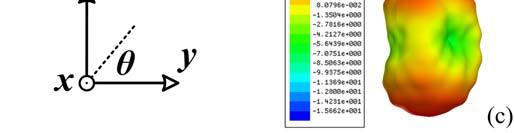
322 Figure 6.21 Simulated gain patterns in x-z and y-z planes for the circularly polarized case at (a) 16 GHz, (b) 20 GHz, and (c) 24 GHz. Figure 6.22 Simulated 3D radiation patterns for the circularly polarized case at (a) 16 GHz, (b) 20 GHz, and (c) 24 GHz. 284


323 Figure 6.23 Simulated electric field distribution at 20 GHz for the CP case at different stages in time domain. The electrical field is plotted along the metal where only the vertical component exists. Figure 6.24 Simulated AR in y-z plane at four different frequencies. Figure 6.25 Simulated AR versus frequency at θ = 0 and 180 point (Z-axis). 285
324 (a) Figure 6.26 Simulated performance for the three-section branch-line 90 coupler. (a) S- parameters; (b) Phase performance. The structure is shown in the inset. (b) 20 GHz. It is seen that the ground also participates in the radiation. A left-hand (clockwise) rotated field is detected which reveals its left-handed circular polarization nature. Figure 6.24 shows the simulated axial ratio (AR) in y-z plane at four different frequencies. Good CP mode is observed in ±z directions with an average 3-dB AR beam width around 80. Figure 6.25 shows the simulated AR versus frequency at ±z axis points. CP radiation is achieved with a 3-dB bandwidth of 53.7%. 286
325 6.2.4 Feeding Circuit Design To obtain the feedings with 90 phase difference and equal power division, a broadband three-stage branch-line coupler is designed and optimized covering the frequency range from 17 GHz to 26 GHz [26]. The configuration of the coupler is presented in the inset of Figure 6.26(b). It is synthesized on the Rogers 5880 substrate with a thickness of mm. It consists of four vertical and six horizontal λg / 4 lines whose impedances are optimized to exhibit a good wideband matching over the interested band [26]. The corresponding line impedances shown in the figure are Z 1 = Ω, Z 2 = 43.7 Ω, Z 3 = 91.2 Ω, Z 4 = 40.2 Ω, and Z 0 = 50 Ω. The overall coupler size is around 25 mm 22 mm. The simulated S-parameters and phase response are displayed in Figure Small reflection (below -15 db), good amplitude imbalance (less than 0.5 db), small phase variation (less than ±2 ), and large isolation (better than 14 db) are realized across the designed frequency range Experimental Results Here we only experimentally verified the circularly polarized case which has the most complicated scenario. Generally speaking, the linearly polarized cases would work as long as the feasibility of the circularly polarized case is proved. The broadband branchline coupler and the antenna are integrated together and fabricated on the mm Rogers 5880 substrate. Figure 6.27 shows a photograph of the fabricated device. The S- parameters measured using a network analyzer are presented in Figure 6.28 compared with the simulated results. Good matching and isolation are observed. The antenna was then measured in a near-field chamber in our department to obtain its radiation 287

 and")

 AR versus")
326 Figure 6.27 Photograph of the fabricated polarization diversity antenna. Figure 6.28 Measured (dotted line) and simulated (solid line) S-parameters of the antenna shown in Figure Figure 6.29 Measured (solid line) and simulated (dotted line) AR versus frequency at θ = 0 and 180 point (z-axis). 288


327 Figure 6.30 Measured (right) and simulated (left) normalized radiation patterns in x-z and y-z planes at (a) 20 GHz, and (b) 24 GHz. performance. Figure 6.29 shows the measured AR in ±z directions at different frequencies. Good CP performance is detected from 19 GHz to 25 GHz. The discrepancy compared with the simulation may come from several aspects such as the influence of the fabrication error and the connectors. Figure 6.30 shows the measured normalized radiation patterns at 20 and 24 GHz. The measured antenna peak gain is approximately 3.0 dbi at 20 GHz and 4.2 dbi at 24 GHz. Figure 6.31 shows the measured and simulated AR at 24 GHz in x-z and y-z planes for the antenna. CP radiation is observed but the measured 3-dB AR beam width decreases compared with the simulated data which are 289

 Front side, and (b) Back side.")


328 (a) Figure 6.31 Measured and simulated AR in x-z and y-z planes at 24 GHz. (a) Front side, and (b) Back side. (b) probably due to the fabrication error and the influence of the branch-line coupler. Overall the measured results verify that this proposed antenna is able to provide polarization diversity performance in Ku- and K-band. 290
A MINIATURIZED UWB BPF BASED ON NOVEL SCRLH TRANSMISSION LINE STRUCTURE
 Progress In Electromagnetics Research Letters, Vol. 19, 67 73, 2010 A MINIATURIZED UWB BPF BASED ON NOVEL SCRLH TRANSMISSION LINE STRUCTURE J.-K. Wang and Y.-J. Zhao College of Information Science and
Miniaturization of Branch-Line Coupler Using Composite Right/Left-Handed Transmission Lines with Novel Meander-shaped-slots CSSRR
 66 H. Y. ZENG, G. M. WANG, ET AL., MINIATURIZATION OF BRANCH-LINE COUPLER USING CRLH-TL WITH NOVEL MSSS CSSRR Miniaturization of Branch-Line Coupler Using Composite Right/Left-Handed Transmission Lines
Compact Circularly Polarized Patch Antenna Using a Composite Right/Left-Handed Transmission Line Unit-Cell
 286 LIN GENG, GUANG-MING WANG, ET AL., COMPACT CP PATCH ANTENNA USING A CRLH TL UNIT-CELL Compact Circularly Polarized Patch Antenna Using a Composite Right/Left-Handed Transmission Line Unit-Cell Lin
RF AND MICROWAVE ENGINEERING
 RF AND MICROWAVE ENGINEERING FUNDAMENTALS OF WIRELESS COMMUNICATIONS Frank Gustrau Dortmund University of Applied Sciences and Arts, Germany WILEY A John Wiley & Sons, Ltd., Publication Preface List of
Compact Broadband End-Fire Antenna with Metamaterial Transmission Line
 Progress In Electromagnetics Research Letters, Vol. 73, 37 44, 2018 Compact Broadband End-Fire Antenna with Metamaterial Transmission Line Liang-Yuan Liu * and Jing-Qi Lu Abstract A broadband end-fire
Keywords: Array antenna; Metamaterial structure; Microstrip antenna; Split ring resonator
 International Journal of Technology (2016) 4: 683-690 ISSN 2086-9614 IJTech 2016 LEFT-HANDED METAMATERIAL (LHM) STRUCTURE STACKED ON A TWO- ELEMENT MICROSTRIP ANTENNA ARRAY Fitri Yuli Zulkifli 1*, Nugroho
ELECTROMAGNETIC METAMATERIALS: TRANSMISSION LINE THEORY AND MICROWAVE APPLICATIONS
 ELECTROMAGNETIC METAMATERIALS: TRANSMISSION LINE THEORY AND MICROWAVE APPLICATIONS The Engineering Approach CHRISTOPHE CALOZ Ecole Polytechnique de Montreal TATSUO ITOH University of California at Los
Two-dimensional beam steering array using planar eight-element composite right/left-handed leaky-wave antennas
 RADIO SCIENCE, VOL. 43,, doi:10.1029/2007rs003800, 2008 Two-dimensional beam steering array using planar eight-element composite right/left-handed leaky-wave antennas Atsushi Sanada 1 Received 4 December
CHAPTER 2 MICROSTRIP REFLECTARRAY ANTENNA AND PERFORMANCE EVALUATION
 43 CHAPTER 2 MICROSTRIP REFLECTARRAY ANTENNA AND PERFORMANCE EVALUATION 2.1 INTRODUCTION This work begins with design of reflectarrays with conventional patches as unit cells for operation at Ku Band in
Single-Fed Low-Profile Circularly Polarized Antenna Using Quarter-Mode Substrate Integrated Waveguide with Enhanced Bandwidth
 Progress In Electromagnetics Research C, Vol. 84, 135 145, 18 Single-Fed Low-Profile Circularly Polarized Antenna Using Quarter-Mode Substrate Integrated Waveguide with Enhanced Bandwidth Ni Wang 1, *,
DESIGN OF LEAKY WAVE ANTENNA WITH COM- POSITE RIGHT-/LEFT-HANDED TRANSMISSION LINE STRUCTURE FOR CIRCULAR POLARIZATION RADIA- TION
 Progress In Electromagnetics Research C, Vol. 33, 109 121, 2012 DESIGN OF LEAKY WAVE ANTENNA WITH COM- POSITE RIGHT-/LEFT-HANDED TRANSMISSION LINE STRUCTURE FOR CIRCULAR POLARIZATION RADIA- TION M. Ishii
Electromagnetic Band Gap Structures in Antenna Engineering
 Electromagnetic Band Gap Structures in Antenna Engineering FAN YANG University of Mississippi YAHYA RAHMAT-SAMII University of California at Los Angeles Hfl CAMBRIDGE Щ0 UNIVERSITY PRESS Contents Preface
TABEL OF CONTENTS. vii CHAPTER TITLE PAGE. TITLE i DECLARATION ii DEDICATION. iii ACKNOWLEDGMENT. iv ABSTRACT. v ABSTRAK vi TABLE OF CONTENTS
 vii TABEL OF CONTENTS CHAPTER TITLE PAGE TITLE i DECLARATION ii DEDICATION iii ACKNOWLEDGMENT iv ABSTRACT v ABSTRAK vi TABLE OF CONTENTS vii LIST OF TABLES xii LIST OF FIGURES xiii LIST OF SYMBOLS xvi
A NOVEL DUAL-BAND PATCH ANTENNA FOR WLAN COMMUNICATION. E. Wang Information Engineering College of NCUT China
 Progress In Electromagnetics Research C, Vol. 6, 93 102, 2009 A NOVEL DUAL-BAND PATCH ANTENNA FOR WLAN COMMUNICATION E. Wang Information Engineering College of NCUT China J. Zheng Beijing Electro-mechanical
DESIGN OF A DUAL-BAND METAMATERIAL BAND- PASS FILTER USING ZEROTH ORDER RESONANCE
 Progress In Electromagnetics Research C, Vol. 12, 149 162, 2010 DESIGN OF A DUAL-BAND METAMATERIAL BAND- PASS FILTER USING ZEROTH ORDER RESONANCE G. Jang and S. Kahng Department of Information and Telecommunication
A Compact Band-selective Filter and Antenna for UWB Application
 PIERS ONLINE, VOL. 3, NO. 7, 7 153 A Compact Band-selective Filter and Antenna for UWB Application Yohan Jang, Hoon Park, Sangwook Jung, and Jaehoon Choi Department of Electrical and Computer Engineering,
RCS Reduction of Patch Array Antenna by Complementary Split-Ring Resonators Structure
 Progress In Electromagnetics Research C, Vol. 51, 95 101, 2014 RCS Reduction of Patch Array Antenna by Complementary Split-Ring Resonators Structure Jun Zheng 1, 2, Shaojun Fang 1, Yongtao Jia 3, *, and
METAMATERIAL BASED NOVEL DUAL BAND ANTENNA
 METAMATERIAL BASED NOVEL DUAL BAND ANTENNA Er.Maninder Singh 1, Er.Ravinder Kumar 2, Er.Neeraj Kumar Sharma 3 1, 2 & 3 Assistant Professor at Department of ECE, Saint Soldier Institute of Engineering &
GPS Patch Antenna Loaded with Fractal EBG Structure Using Organic Magnetic Substrate
 Progress In Electromagnetics Research Letters, Vol. 58, 23 28, 2016 GPS Patch Antenna Loaded with Fractal EBG Structure Using Organic Magnetic Substrate Encheng Wang * and Qiuping Liu Abstract In this
Circular Patch Antenna with CPW fed and circular slots in ground plane.
 Circular Patch Antenna with CPW fed and circular slots in ground plane. Kangan Saxena, USICT, Guru Gobind Singh Indraprastha University, Delhi-75 ---------------------------------------------------------------------***---------------------------------------------------------------------
DESIGN OF A NOVEL WIDEBAND LOOP ANTENNA WITH PARASITIC RESONATORS. Microwaves, Xidian University, Xi an, Shaanxi, China
 Progress In Electromagnetics Research Letters, Vol. 37, 47 54, 2013 DESIGN OF A NOVEL WIDEBAND LOOP ANTENNA WITH PARASITIC RESONATORS Shoutao Fan 1, *, Shufeng Zheng 1, Yuanming Cai 1, Yingzeng Yin 1,
A NOVEL VIA LESS RESONANT TYPE ANTENNA BA- SED ON COMPOSITE RIGHT/LEFT-HANDED TRANS- MISSION LINE (CRLH-TL) UNIT CELL WITH DE- FECTED GROUND STRUCTURE
 UNIT CELL WITH DE- FECTED GROUND STRUCTURE") Progress In Electromagnetics Research Letters, Vol. 38, 55 64, 213 A NOVEL VIA LESS RESONANT TYPE ANTENNA BA- SED ON COMPOSITE RIGHT/LEFT-HANDED TRANS- MISSION LINE (CRLH-TL) UNIT CELL WITH DE- FECTED
Progress In Electromagnetics Research Letters, Vol. 38, 55 64, 213 A NOVEL VIA LESS RESONANT TYPE ANTENNA BA- SED ON COMPOSITE RIGHT/LEFT-HANDED TRANS- MISSION LINE (CRLH-TL) UNIT CELL WITH DE- FECTED
A COMPACT MULTIBAND MONOPOLE ANTENNA FOR WLAN/WIMAX APPLICATIONS
 Progress In Electromagnetics Research Letters, Vol. 23, 147 155, 2011 A COMPACT MULTIBAND MONOPOLE ANTENNA FOR WLAN/WIMAX APPLICATIONS Z.-N. Song, Y. Ding, and K. Huang National Key Laboratory of Antennas
Compact Triple-Band Monopole Antenna with Inverted-L Slots and SRR for WLAN/WiMAX Applications
 Progress In Electromagnetics Research Letters, Vol. 55, 1 6, 2015 Compact Triple-Band Monopole Antenna with Inverted-L Slots and SRR for WLAN/WiMAX Applications Yuan Xu *, Cilei Zhang, Yingzeng Yin, and
Design of Low-Index Metamaterial Lens Used for Wideband Circular Polarization Antenna
 Progress In Electromagnetics Research Letters, Vol. 68, 93 98, 2017 Design of Low-Index Metamaterial Lens Used for Wideband Circular Polarization Antenna Yong Wang and Yanlin Zou * Abstract A novel low-index
ON THE STUDY OF LEFT-HANDED COPLANAR WAVEGUIDE COUPLER ON FERRITE SUBSTRATE
 Progress In Electromagnetics Research Letters, Vol. 1, 69 75, 2008 ON THE STUDY OF LEFT-HANDED COPLANAR WAVEGUIDE COUPLER ON FERRITE SUBSTRATE M. A. Abdalla and Z. Hu MACS Group, School of EEE University
A VARACTOR-TUNABLE HIGH IMPEDANCE SURFACE FOR ACTIVE METAMATERIAL ABSORBER
 Progress In Electromagnetics Research C, Vol. 43, 247 254, 2013 A VARACTOR-TUNABLE HIGH IMPEDANCE SURFACE FOR ACTIVE METAMATERIAL ABSORBER Bao-Qin Lin *, Shao-Hong Zhao, Qiu-Rong Zheng, Meng Zhu, Fan Li,
Broadband Circular Polarized Antenna Loaded with AMC Structure
 Progress In Electromagnetics Research Letters, Vol. 76, 113 119, 2018 Broadband Circular Polarized Antenna Loaded with AMC Structure Yi Ren, Xiaofei Guo *,andchaoyili Abstract In this paper, a novel broadband
ENHANCEMENT OF PRINTED DIPOLE ANTENNAS CHARACTERISTICS USING SEMI-EBG GROUND PLANE
 J. of Electromagn. Waves and Appl., Vol. 2, No. 8, 993 16, 26 ENHANCEMENT OF PRINTED DIPOLE ANTENNAS CHARACTERISTICS USING SEMI-EBG GROUND PLANE F. Yang, V. Demir, D. A. Elsherbeni, and A. Z. Elsherbeni
A Wideband Magneto-Electric Dipole Antenna with Improved Feeding Structure
 ADVANCED ELECTROMAGNETICS, VOL. 5, NO. 2, AUGUST 2016 ` A Wideband Magneto-Electric Dipole Antenna with Improved Feeding Structure Neetu Marwah 1, Ganga P. Pandey 2, Vivekanand N. Tiwari 1, Sarabjot S.
DESIGN OF A NOVEL MICROSTRIP-FED DUAL-BAND SLOT ANTENNA FOR WLAN APPLICATIONS
 Progress In Electromagnetics Research Letters, Vol. 13, 75 81, 2010 DESIGN OF A NOVEL MICROSTRIP-FED DUAL-BAND SLOT ANTENNA FOR WLAN APPLICATIONS S. Gai, Y.-C. Jiao, Y.-B. Yang, C.-Y. Li, and J.-G. Gong
A Compact Miniaturized Frequency Selective Surface with Stable Resonant Frequency
 Progress In Electromagnetics Research Letters, Vol. 62, 17 22, 2016 A Compact Miniaturized Frequency Selective Surface with Stable Resonant Frequency Ning Liu 1, *, Xian-Jun Sheng 2, and Jing-Jing Fan
Quad-Band Circularly Polarized Patch Antenna for UWB/5G Applications
 International Journal of Computer Engineering in Research Trends Multidisciplinary, Open Access, Peer-Reviewed and fully refereed Research Paper Volume-6, Issue-3, 2019 Regular Edition ISSN: 2349-7084
Novel High-Selectivity Dual-Band Substrate Integrated Waveguide Filter with Multi-Transmission Zeros
 Progress In Electromagnetics Research Letters, Vol. 47, 7 12, 214 Novel High-Selectivity Dual-Band Substrate Integrated Waveguide Filter with Multi-Transmission Zeros Guo-Hui Li *, Xiao-Qi Cheng, Hao Jian,
Planar Leaky-Wave Antennas Based on Microstrip Line and Substrate Integrated Waveguide (SIW)
") Forum for Electromagnetic Research Methods and Application Technologies (FERMAT) Planar Leaky-Wave Antennas Based on Microstrip Line and Substrate Integrated Waveguide (SIW) Dr. Juhua Liu liujh33@mail.sysu.edu.cn
Forum for Electromagnetic Research Methods and Application Technologies (FERMAT) Planar Leaky-Wave Antennas Based on Microstrip Line and Substrate Integrated Waveguide (SIW) Dr. Juhua Liu liujh33@mail.sysu.edu.cn
Compact Microstrip Magnetic Yagi Antenna and Array with Vertical Polarization Based on Substrate Integrated Waveguide
 Progress In Electromagnetics Research C, Vol. 59, 135 141, 215 Compact Microstrip Magnetic Yagi Antenna and Array with Vertical Polarization Based on Substrate Integrated Waveguide Zhao Zhang *, Xiangyu
QUADRI-FOLDED SUBSTRATE INTEGRATED WAVEG- UIDE CAVITY AND ITS MINIATURIZED BANDPASS FILTER APPLICATIONS
 Progress In Electromagnetics Research C, Vol. 23, 1 14, 2011 QUADRI-FOLDED SUBSTRATE INTEGRATED WAVEG- UIDE CAVITY AND ITS MINIATURIZED BANDPASS FILTER APPLICATIONS C. A. Zhang, Y. J. Cheng *, and Y. Fan
Metamaterial Inspired CPW Fed Compact Low-Pass Filter
 Progress In Electromagnetics Research C, Vol. 57, 173 180, 2015 Metamaterial Inspired CPW Fed Compact Low-Pass Filter BasilJ.Paul 1, *, Shanta Mridula 1,BinuPaul 1, and Pezholil Mohanan 2 Abstract A metamaterial
A Dual-Polarized MIMO Antenna with EBG for 5.8 GHz WLAN Application
 Progress In Electromagnetics Research Letters, Vol. 51, 15 2, 215 A Dual-Polarized MIMO Antenna with EBG for 5.8 GHz WLAN Application Xiaoyan Zhang 1, 2, *, Xinxing Zhong 1,BinchengLi 3, and Yiqiang Yu
COMPACT SLOT ANTENNA WITH EBG FEEDING LINE FOR WLAN APPLICATIONS
 Progress In Electromagnetics Research C, Vol. 10, 87 99, 2009 COMPACT SLOT ANTENNA WITH EBG FEEDING LINE FOR WLAN APPLICATIONS A. Danideh Department of Electrical Engineering Islamic Azad University (IAU),
Miniature Multiband Antenna for WLAN and X-Band Satellite Communication Applications
 Progress In Electromagnetics Research Letters, Vol. 75, 13 18, 2018 Miniature Multiband Antenna for WLAN and X-Band Satellite Communication Applications Ruixing Zhi, Mengqi Han, Jing Bai, Wenying Wu, and
A Broadband Reflectarray Using Phoenix Unit Cell
 Progress In Electromagnetics Research Letters, Vol. 50, 67 72, 2014 A Broadband Reflectarray Using Phoenix Unit Cell Chao Tian *, Yong-Chang Jiao, and Weilong Liang Abstract In this letter, a novel broadband
A Compact Microstrip Patch Antenna Based on Metamaterials for Wi-Fi and WiMAX Applications
 JOURNAL OF ELECTROMAGNETIC ENGINEERING AND SCIENCE, VOL. 18, NO. 3, 182~187, JUL. 2018 https://doi.org/10.26866/jees.2018.18.3.182 ISSN 2234-8395 (Online) ISSN 2234-8409 (Print) A Compact Microstrip Patch
Planar Wideband Balun with Novel Slotline T-Junction Transition
 Progress In Electromagnetics Research Letters, Vol. 64, 73 79, 2016 Planar Wideband Balun with Novel Slotline T-Junction Transition Ya-Li Yao*, Fu-Shun Zhang, Min Liang, and Mao-Ze Wang Abstract A planar
Design and Development of a 2 1 Array of Slotted Microstrip Line Fed Shorted Patch Antenna for DCS Mobile Communication System
 Wireless Engineering and Technology, 2013, 4, 59-63 http://dx.doi.org/10.4236/wet.2013.41009 Published Online January 2013 (http://www.scirp.org/journal/wet) 59 Design and Development of a 2 1 Array of
DUAL-BAND LOW PROFILE DIRECTIONAL ANTENNA WITH HIGH IMPEDANCE SURFACE REFLECTOR
 Progress In Electromagnetics Research Letters, Vol. 25, 67 75, 211 DUAL-BAND LOW PROFILE DIRECTIONAL ANTENNA WITH HIGH IMPEDANCE SURFACE REFLECTOR X. Mu *, W. Jiang, S.-X. Gong, and F.-W. Wang Science
Determination of Transmission and Reflection Parameters by Analysis of Square Loop Metasurface
 Determination of Transmission and Reflection Parameters by Analysis of Square Loop Metasurface Anamika Sethi #1, Rajni *2 #Research Scholar, ECE Department, MRSPTU, INDIA *Associate Professor, ECE Department,
The Basics of Patch Antennas, Updated
 The Basics of Patch Antennas, Updated By D. Orban and G.J.K. Moernaut, Orban Microwave Products www.orbanmicrowave.com Introduction This article introduces the basic concepts of patch antennas. We use
ADVANCES in NATURAL and APPLIED SCIENCES
 ADVANCES in NATURAL and APPLIED SCIENCES ISSN: 1995-0772 Published BYAENSI Publication EISSN: 1998-1090 http://www.aensiweb.com/anas 2017 May 11(7):pages 52-56 Open Access Journal Design and Modeling of
A CPW-fed Microstrip Fork-shaped Antenna with Dual-band Circular Polarization
 Machine Copy for Proofreading, Vol. x, y z, 2016 A CPW-fed Microstrip Fork-shaped Antenna with Dual-band Circular Polarization Chien-Jen Wang and Yu-Wei Cheng * Abstract This paper presents a microstrip
Metamaterial-Inspired Miniaturized Multi-Band Microwave Filters and Power Dividers
 Utah State University DigitalCommons@USU All Graduate Theses and Dissertations Graduate Studies 5-2010 Metamaterial-Inspired Miniaturized Multi-Band Microwave Filters and Power Dividers Alper Genc Utah
METAMATERIAL ANTENNAS USED FOR WIRELESS APPLICATIONS
 METAMATERIAL ANTENNAS USED FOR WIRELESS APPLICATIONS N. R. Indira 1 and A. Thenmozhi 2 1 Department of Electronics and Communication Engineering, Sethu Institute of Technology, Madurai, India 2 Department
DESIGN OF COMPACT MICROSTRIP LOW-PASS FIL- TER WITH ULTRA-WIDE STOPBAND USING SIRS
 Progress In Electromagnetics Research Letters, Vol. 18, 179 186, 21 DESIGN OF COMPACT MICROSTRIP LOW-PASS FIL- TER WITH ULTRA-WIDE STOPBAND USING SIRS L. Wang, H. C. Yang, and Y. Li School of Physical
Meta-Loaded Circular Sector Patch Antenna
 Progress In Electromagnetics Research, Vol. 156, 37 46, 2016 Meta-Loaded Circular Sector Patch Antenna Sen Yan * and Guy A. E. Vandenbosch Abstract A circular sector patch antenna loaded with a periodic
Lines and Slotlines. Microstrip. Third Edition. Ramesh Garg. Inder Bahl. Maurizio Bozzi ARTECH HOUSE BOSTON LONDON. artechhouse.
 Microstrip Lines and Slotlines Third Edition Ramesh Garg Inder Bahl Maurizio Bozzi ARTECH HOUSE BOSTON LONDON artechhouse.com Contents Preface xi Microstrip Lines I: Quasi-Static Analyses, Dispersion Models,
HYBRID ARRAY ANTENNA FOR BROADBAND MILLIMETER-WAVE APPLICATIONS
 Progress In Electromagnetics Research, PIER 83, 173 183, 2008 HYBRID ARRAY ANTENNA FOR BROADBAND MILLIMETER-WAVE APPLICATIONS S. Costanzo, I. Venneri, G. Di Massa, and G. Amendola Dipartimento di Elettronica,
COMPACT FRACTAL MONOPOLE ANTENNA WITH DEFECTED GROUND STRUCTURE FOR WIDE BAND APPLICATIONS
 COMPACT FRACTAL MONOPOLE ANTENNA WITH DEFECTED GROUND STRUCTURE FOR WIDE BAND APPLICATIONS 1 M V GIRIDHAR, 2 T V RAMAKRISHNA, 2 B T P MADHAV, 3 K V L BHAVANI 1 M V REDDIAH BABU, 1 V SAI KRISHNA, 1 G V
Broadband and Gain Enhanced Bowtie Antenna with AMC Ground
 Progress In Electromagnetics Research Letters, Vol. 61, 25 30, 2016 Broadband and Gain Enhanced Bowtie Antenna with AMC Ground Xue-Yan Song *, Chuang Yang, Tian-Ling Zhang, Ze-Hong Yan, and Rui-Na Lian
NOVEL PLANAR MULTIMODE BANDPASS FILTERS WITH RADIAL-LINE STUBS
 Progress In Electromagnetics Research, PIER 101, 33 42, 2010 NOVEL PLANAR MULTIMODE BANDPASS FILTERS WITH RADIAL-LINE STUBS L. Zhang, Z.-Y. Yu, and S.-G. Mo Institute of Applied Physics University of Electronic
Novel Substrate Integrated Waveguide Filters and Circuits
 Novel Substrate Integrated Waveguide Filters and Circuits Liwen Huang Submitted in accordance with the requirements for the degree of Doctor of Philosophy The University of Leeds School of Electrical and
Gain Enhancement and Wideband RCS Reduction of a Microstrip Antenna Using Triple-Band Planar Electromagnetic Band-Gap Structure
 Progress In Electromagnetics Research Letters, Vol. 65, 103 108, 2017 Gain Enhancement and Wideband RCS Reduction of a Microstrip Antenna Using Triple-Band Planar Electromagnetic Band-Gap Structure Yang
A Compact Dual Band-Notched Ultrawideband Antenna with λ/4 Stub and Open Slots
 Progress In Electromagnetics Research C, Vol. 49, 133 139, 2014 A Compact Dual Band-Notched Ultrawideband Antenna with λ/4 Stub and Open Slots Jian Ren * and Yingzeng Yin Abstract A novel compact UWB antenna
A RECONFIGURABLE HYBRID COUPLER CIRCUIT FOR AGILE POLARISATION ANTENNA
 A RECONFIGURABLE HYBRID COUPLER CIRCUIT FOR AGILE POLARISATION ANTENNA F. Ferrero (1), C. Luxey (1), G. Jacquemod (1), R. Staraj (1), V. Fusco (2) (1) Laboratoire d'electronique, Antennes et Télécommunications
Antenna Theory and Design
 Antenna Theory and Design Antenna Theory and Design Associate Professor: WANG Junjun 王珺珺 School of Electronic and Information Engineering, Beihang University F1025, New Main Building wangjunjun@buaa.edu.cn
Designs of Substrate Integrated Waveguide (SIW) and Its Transition to Rectangular Waveguide. Ya Guo
 and Its Transition to Rectangular Waveguide. Ya Guo") Designs of Substrate Integrated Waveguide (SIW) and Its Transition to Rectangular Waveguide by Ya Guo A thesis submitted to the Graduate Faculty of Auburn University in partial fulfillment of the requirements
Designs of Substrate Integrated Waveguide (SIW) and Its Transition to Rectangular Waveguide by Ya Guo A thesis submitted to the Graduate Faculty of Auburn University in partial fulfillment of the requirements
Improvement of Antenna Radiation Efficiency by the Suppression of Surface Waves
 Journal of Electromagnetic Analysis and Applications, 2011, 3, 79-83 doi:10.4236/jemaa.2011.33013 Published Online March 2011 (http://www.scirp.org/journal/jemaa) 79 Improvement of Antenna Radiation Efficiency
2017 IEEE. Personal use of this material is permitted. Permission from IEEE must be obtained for all other uses, in any current or future media,
 2017 IEEE. Personal use of this material is permitted. Permission from IEEE must be obtained for all other uses, in any current or future media, including reprinting/republishing this material for advertising
Compact UWB Planar Antenna with Triple Band EMI Reduction Characteristics for WiMAX/WLAN/X-Band Satellite Downlink Frequency
 Progress In Electromagnetics Research M, Vol. 1, 13 131, 17 Compact UWB Planar Antenna with Triple Band EMI Reduction Characteristics for WiMAX/WLAN/X-Band Satellite Downlink Frequency Priyanka Usha *
A Miniaturized Directional Coupler Using Complementary Split Ring Resonator and Dumbbell-Like Defected Ground Structure
 Progress In Electromagnetics Research Letters, Vol. 63, 53 57, 216 A Miniaturized Directional Coupler Using Complementary Split Ring Resonator and Dumbbell-Like Defected Ground Structure Lizhong Song 1,
Double Negative Left-Handed Metamaterials for Miniaturization of Rectangular Microstrip Antenna
 J. Electromagnetic Analysis & Applications, 2010, 2, 347-351 doi:10.4236/jemaa.2010.26044 Published Online June 2010 (http://www.scirp.org/journal/jemaa) 347 Double Negative Left-Handed Metamaterials for
Serrated Circular Fractal Coplanar Wave Guide Fed Antennas for Wideband and Ultra Wideband Applications
 Serrated Circular Fractal Coplanar Wave Guide Fed Antennas for Wideband and Ultra Wideband Applications Serrated Circular Fractal Coplanar Wave Guide Fed Antennas for Wideband and Ultra Wideband Applications
Compact Complementary Folded Triangle Split Ring Resonator Triband Mobile Handset Planar Antenna for Voice and Wi-Fi Applications
 Progress In Electromagnetics Research C, Vol. 91, 53 64, 19 Compact Complementary Folded Triangle Split Ring Resonator Triband Mobile Handset Planar Antenna for Voice and Wi-Fi Applications P. Rajalakshmi
White Rose Research Online URL for this paper: Version: Accepted Version
 This is a repository copy of Compact half-mode substrate integrated waveguide bandpass filters with capacitively loaded complementary single split ring resonators. White Rose Research Online URL for this
A Novel Dual-Band SIW Filter with High Selectivity
 Progress In Electromagnetics Research Letters, Vol. 6, 81 88, 216 A Novel Dual-Band SIW Filter with High Selectivity Yu-Dan Wu, Guo-Hui Li *, Wei Yang, and Tong Mou Abstract A novel dual-band substrate
Chapter 7 Design of the UWB Fractal Antenna
 Chapter 7 Design of the UWB Fractal Antenna 7.1 Introduction F ractal antennas are recognized as a good option to obtain miniaturization and multiband characteristics. These characteristics are achieved
DUAL-MODE SPLIT MICROSTRIP RESONATOR FOR COMPACT NARROWBAND BANDPASS FILTERS. Federal University, Krasnoyarsk , Russia
 Progress In Electromagnetics Research C, Vol. 23, 151 160, 2011 DUAL-MODE SPLIT MICROSTRIP RESONATOR FOR COMPACT NARROWBAND BANDPASS FILTERS V. V. Tyurnev 1, * and A. M. Serzhantov 2 1 Kirensky Institute
A PERTURBED CIRCULAR MONOPOLE ANTENNA WITH CIRCULAR POLARIZATION FOR ULTRA WIDEBAND APPLICATIONS
 A PERTURBED CIRCULAR MONOPOLE ANTENNA WITH CIRCULAR POLARIZATION FOR ULTRA WIDEBAND APPLICATIONS Diptimayee Konhar #1, Debasis Mishra *2 # Dept. Of Electronics and Telecomm Engineering, Veer SurendraSai
DIVERSITY MONOPULSE ANTENNA BASED ON A DUAL-FREQUENCY AND DUAL MODE CRLH RAT- RACE COUPLER
 Progress In Electromagnetics Research B, Vol. 14, 87 106, 2009 DIVERSITY MONOPULSE ANTENNA BASED ON A DUAL-FREQUENCY AND DUAL MODE CRLH RAT- RACE COUPLER D. de Castro Galán,L.E.García Muñoz and D. Segovia
A NOVEL MICROSTRIP LC RECONFIGURABLE BAND- PASS FILTER
 Progress In Electromagnetics Research Letters, Vol. 36, 171 179, 213 A NOVEL MICROSTRIP LC RECONFIGURABLE BAND- PASS FILTER Qianyin Xiang, Quanyuan Feng *, Xiaoguo Huang, and Dinghong Jia School of Information
Citation Electromagnetics, 2012, v. 32 n. 4, p
 Title Low-profile microstrip antenna with bandwidth enhancement for radio frequency identification applications Author(s) Yang, P; He, S; Li, Y; Jiang, L Citation Electromagnetics, 2012, v. 32 n. 4, p.
A New UWB Antenna with Band-Notched Characteristic
 Progress In Electromagnetics Research M, Vol. 74, 201 209, 2018 A New UWB Antenna with Band-Notched Characteristic Meixia Shi, Lingzhi Cui, Hui Liu, Mingming Lv, and Xubao Sun Abstract A new coplanar waveguide
Dielectric Filled Printed Gap Waveguide for Millimeter Wave Applications
 Dielectric Filled Printed Gap Waveguide for Millimeter Wave Applications Jing Zhang A Thesis In the Department of Electrical and Computer Engineering Presented in Partial Fulfillment of the Requirements
COMPACT WIDE-SLOT TRI-BAND ANTENNA FOR WLAN/WIMAX APPLICATIONS
 Progress In Electromagnetics Research Letters, Vol. 18, 9 18, 2010 COMPACT WIDE-SLOT TRI-BAND ANTENNA FOR WLAN/WIMAX APPLICATIONS Q. Zhao, S. X. Gong, W. Jiang, B. Yang, and J. Xie National Laboratory
UCLA UCLA Previously Published Works
 UCLA UCLA Previously Published Works Title A novel patch antenna with switchable slot (PASS): Dual-frequency operation with reversed circular polarizations Permalink https://escholarship.org/uc/item/0cz5761t
FILTERING ANTENNAS: SYNTHESIS AND DESIGN
 FILTERING ANTENNAS: SYNTHESIS AND DESIGN Deepika Agrawal 1, Jagadish Jadhav 2 1 Department of Electronics and Telecommunication, RCPIT, Maharashtra, India 2 Department of Electronics and Telecommunication,
Fully Integrated Solar Panel Slot Antennas for Small Satellites
 Fully Integrated Solar Panel Slot Antennas for Small Satellites Mahmoud N. Mahmoud, Reyhan Baktur Department of Electrical and Computer Engineering Utah State University, Logan, UT Robert Burt Space Dynamics
A Folded SIR Cross Coupled WLAN Dual-Band Filter
 Progress In Electromagnetics Research Letters, Vol. 45, 115 119, 2014 A Folded SIR Cross Coupled WLAN Dual-Band Filter Zi Jian Su *, Xi Chen, Long Li, Bian Wu, and Chang-Hong Liang Abstract A compact cross-coupled
A Wideband Dual-polarized Modified Bowtie Antenna for 2G/3G/LTE Base-station Applications
 Progress In Electromagnetics Research Letters, Vol. 61, 131 137, 2016 A Wideband Dual-polarized Modified Bowtie Antenna for 2G/3G/LTE Base-station Applications Zhao Yang *, Cilei Zhang, Yingzeng Yin, and
Dielectric Resonator Antenna Design For UWB Applications
 Presentation description of LAPC paper / poster entitled Dielectric Resonator Antenna Design For UWB Applications F. Elmegri, A. H. Al-Qaysi, C.H. See, R.A. Abd-Alhameed, C. Zebiri and P.S. Excell This
Design of Substrate-Integrated Waveguide Slot Antenna with AZIM Coating
 Design of Substrate-Integrated Waveguide Slot Antenna with Coating Pomal Dhara Anantray 1, Prof. Satish Ramdasji Bhoyar 2 1 Student, Electronics and Telecommunication, Rajiv Gandhi Institute of Technology,
UWB ANTENNA WITH DUAL BAND REJECTION FOR WLAN/WIMAX BANDS USING CSRRs
 Progress In Electromagnetics Research Letters, Vol. 26, 69 78, 2011 UWB ANTENNA WITH DUAL BAND REJECTION FOR WLAN/WIMAX BANDS USING CSRRs H.-Y. Lai *, Z.-Y. Lei, Y.-J. Xie, G.-L. Ning, and K. Yang Science
A Phase Diversity Printed-Dipole Antenna Element for Patterns Selectivity Array Application
 Progress In Electromagnetics Research Letters, Vol. 78, 105 110, 2018 A Phase Diversity Printed-Dipole Antenna Element for Patterns Selectivity Array Application Fukun Sun *, Fushun Zhang, and Chaoqiang
A COMPACT WIDEBAND BANDPASS FILTER USING NOVEL CSRR LOADED QMSIW RESONATOR WITH HIGH SELECTIVITY
 Progress In Electromagnetics Research C, Vol. 41, 239 254, 2013 A COMPACT WIDEBAND BANDPASS FILTER USING NOVEL CSRR LOADED QMSIW RESONATOR WITH HIGH SELECTIVITY Hailin Cao 1, 2, *, Sijia He 1, Hao Li 1,
STUDY OF ARTIFICIAL MAGNETIC MATERIAL FOR MICROWAVE APPLICATIONS
 International Journal of Advances in Materials Science and Engineering (IJAMSE) Vol., No.,July 3 STUDY OF ARTIFICIAL MAGNETIC MATERIAL FOR MICROWAVE APPLICATIONS H. Benosman, N.Boukli Hacene Department
Tunable Microstrip Bandpass Filters Based on Planar Split Ring Resonators
 Tunable Microstrip Bandpass Filters Based on Planar Split Ring Resonators Alper Genc and Reyhan Baktur Department of Electrical and Computer Engineering Utah State University, Logan, UT Introduction Most
Compact Wide-Beam Circularly Polarized Antenna with Stepped Arc-Shaped Arms for CNSS Application
 Progress In Electromagnetics Research C, Vol. 71, 141 148, 2017 Compact Wide-Beam Circularly Polarized Antenna with Stepped Arc-Shaped Arms for CNSS Application Can Wang *, Fushun Zhang, Fan Zhang, Yali
MICROSTRIP PHASE INVERTER USING INTERDIGI- TAL STRIP LINES AND DEFECTED GROUND
 Progress In Electromagnetics Research Letters, Vol. 29, 167 173, 212 MICROSTRIP PHASE INVERTER USING INTERDIGI- TAL STRIP LINES AND DEFECTED GROUND X.-C. Zhang 1, 2, *, C.-H. Liang 1, and J.-W. Xie 2 1
Broadband and High Efficiency Single-Layer Reflectarray Using Circular Ring Attached Two Sets of Phase-Delay Lines
 Progress In Electromagnetics Research M, Vol. 66, 193 202, 2018 Broadband and High Efficiency Single-Layer Reflectarray Using Circular Ring Attached Two Sets of Phase-Delay Lines Fei Xue 1, *, Hongjian
Transmitarrays, reflectarrays and phase shifters for wireless communication systems. Pablo Padilla de la Torre Universidad de Granada
 Transmitarrays, reflectarrays and phase shifters for wireless communication systems Pablo Padilla de la Torre Universidad de Granada Outline 1. Introduction to Transmitarray and Reflectarray structures
Dual Feed Microstrip Patch Antenna for Wlan Applications
 IOSR Journal of Electronics and Communication Engineering (IOSR-JECE) e-issn: 2278-2834,p- ISSN: 2278-8735.Volume 10, Issue 5, Ver. I (Sep - Oct.2015), PP 01-05 www.iosrjournals.org Dual Feed Microstrip