Characteristics Evaluation of Multi-Stage Optical Amplifier EDFA
|
|
|
- Damian Blake
- 5 years ago
- Views:
Transcription


1 British Journal of Applied Science & Technology 19(4): 1-20, 2017; Article no.bjast ISSN: , NLM ID: SCIENCEDOMAIN international Characteristics Evaluation of Multi-Stage Optical Amplifier EDFA Mohamed B. El-Mashade 1* and A. Mohamed 1 1 Department of Electrical Engineering, Faculty of Engineering, Al Azhar University, Nasr City, Cairo, Egypt. Authors contributions This work was carried out in collaboration between both authors. Both authors read and approved the final manuscript. Article Information DOI: /BJAST/2017/31911 Editor(s): (1) Harry E. Ruda, Stan Meek Chair Professor in Nanotechnology, University of Toronto, Director, Centre for Advanced Nanotechnology, University of Toronto, Canada. Reviewers: (1) Tomas Ivaniga, University of Kosice, Kosice, Slovakia. (2) Gaurav Soni, Amritsar College of Engineering & Technology, Amritsar, India. (3) Pinar kirci, Istanbul University, Turkey. Complete Peer review History: Original Research Article Received 30 th January 2017 Accepted 24 th February 2017 Published 22 nd March 2017 ABSTRACT In optical fiber communication systems, the non-perfectly transparent material of the fiber causes the visible-light or infrared beams to be attenuated as they travel through it. This necessitates the use of optical amplifier in order to remedy this signal attenuation. In this regard, the fiber amplifier is a key enabling technology for high speed optical communications. The EDFA is a successful optical amplifier that represents a significant factor in the rapid deployment of optical fiber networks. It uses proven erbium-doped fiber (EDF) technology to allow amplification of an optical signal without the need of costly regenerative repeater stations. Its large gain bandwidth, which allows simultaneous amplification of a numerous number of channels at different wavelengths within the spectrum of nearly constant gain, is very attractive in many practical applications. This property is very useful in WDM which is widely used in optical fiber data links owing to its dominant role that it plays in the next generation of high speed networks. Additionally, it may be positioned as a booster, pre-amp or in-line position to allow the amplification of the signal along any point of the optical network. Moreover, it can efficiently amplify light in the 1.5 μm wavelength region, where telecom fibers have their minimum loss. This paper is intended to the evaluation of multi-stage EDFA performance for different EDF lengths, the two commonly used pumping wavelengths (980 nm & 1480 nm), and the distinct configurations *Corresponding author: MohamedElMashade@Gmail.com, ElMashade@yahoo.com;
2 of pumping mechanism. The gain and noise characteristics of different number of stages are computed and compared through simulation. Our attention is specially paid towards the optimum values of the system parameters that will give highest gain and lowest noise figure as well as minimum bit error rate in order to achieve the longest propagation length without signal degradation. Keywords: Optical communication systems; erbium-doped fiber amplifiers; multi-stage EDFA; optical gain; noise figure; bit error rate. 1. INTRODUCTION To cope with the increase of bandwidth demand and solve the saturation issues in the networks, carriers have to be pushed for increasing the capacity of the already installed communication networks. This requirement is based on the wellknown phenomenon that the greater the carrier frequency leads to more bandwidth along with more information capacity of the underlined system. On the other hand, as the number of users is increasing significantly, there is a growing demand for bandwidth in mobile communication. Therefore, the next-generation wireless communication systems should be able to offer higher capacity to support various broadband wireless services. The currently in use technologies including copper and coaxial cables, wireless internet access, and broadband radio frequency (RF)/microwave have limitations such as congested spectrum, lower data rate, expensive licensing, security issues and high cost of installation and accessibility to all. The development of optical fiber communication, fueled by the need for rapidly increasing volumes of information transfer and by new requirements that are far less predictable than they have been for telephony, moves ever forward. These optical systems have revolutionized the telecommunications industry and have played a major role in the advent of the information age since their emergence. Nowadays, they constitute a key enabler for broadband internet access and services, as well as the main transporter of the internet protocol traffic. Owing to their merits over electrical transmission, optical fibers have been largely deployed in core networks. However, in rural areas, the installation of buried optical fiber cable to provide a high-speed network is not an economic proposition. Additionally, the migration of mobile services to applications requiring broadband services will put increasing demands on mobile network infrastructure. Current systems and base station separations employing the microwave radio technology to provide data links or mobile backhaul network cannot deal with higher data rates and thus leading to the data throughput backhaul bottleneck. The third- and fourth- generation (3G and 4G) wireless communication systems will provide omnipresent connectivity, ranging from high-mobility cellular systems to the fixed and low-mobility indoor environments. Optical wireless communication (OWC) is an age-long technology that entails the transmission of information-laden optical radiation through the free-space channel. OWC technology is one of the most promising alternative schemes for addressing the last mile bottleneck in the emerging broadband access markets. It is an emerging and dynamic research area that has generated a vast number of interesting solutions to very complicated communication challenges such as high data rate, high capacity and minimum interference links for different applications of communication. OWC offers a flexible networking solution that delivers the truly broadband services. Only the OWC technology provides the essential combination of virtues vital to bring the high-speed traffic to the optical fiber backbone. That is offering a license-free spectrum with almost an unlimited data rate, a low cost of development, along with ease and speediness of installation. However, OWC operating at the near-ir region of nm has most of the physical properties of the visible light, except that it is at the lower part of the optical frequency spectrum making it invisible to the human eye which is very sensitive to this wavelength range and therefore must be protected by limiting the transmission intensity. At the higher wavelength region of 1550 nm, the eye is less sensitive to light and, therefore, the eye safety requirement is more relaxed and the interference due to ambient light sources (sun, fluorescence, etc) is considerably reduced. This wavelength is also compatible with the third window backbone optical fiber communication network. Despite the modern technology of fiber fabrication, optical fiber communication losses such as fiber loss and splice loss still occur. Thus, in order to prevent signal degradation over long distance communication, an optical amplifier with good gain and flat gain bandwidth 2
3 is needed. On the other hand, 1550 nm denotes the wavelength of minimum attenuation in optical fibers and represents a wavelength for which an excellent optical amplifier can be built. Of particular importance is the fact that the amplifier may be realized as an optical fiber with a small concentration of erbium atoms in the core. In this regard, Erbium Doped Fiber Amplifier (EDFA) comes into play. EDFA s have the major advantage of being optical amplifiers, with no conversion of the optical signal into electrical signal. It is the crucial element in optical fiber communications today. Whereas electronics today can provide an amplifier bandwidth of a few tens of GHz, the EDFA provides 4 THz of bandwidth in a single amplifier, allowing several wavelength division multiplexed (WDM) channels to be amplified with a single amplifier. Additionally, even though the center frequency depends on temperature, the temperature sensitivity is not sufficient to permit the frequency to be controlled by temperature, considering that the entire bandwidth of an EDFA must be covered. There are plenty of advantages of using EDFAs as optical amplifiers in optical fiber networks. Before the advent of EDFAs, optoelectronic regenerators that include both a receiver and a transmitter were required to compensate attenuation in the middle of a transmission system. With EDFAs, light wave signals are amplified purely in the optical domain: optical signals are amplified directly in optical format without the need for O/E/O conversion, thereby greatly reducing the complexity and cost of systems. Second, EDFAs can be applied to both CW signals and modulated signals if the modulation speed is greater than 1Mbit/s due to the long lifetime of erbium ions in the upper state. Moreover, EDFA exhibits a number of very attractive properties such as high signal gain, wideband amplification, high saturation power, ideal noise performance, low crosstalk between different signals, data bitrate independent, polarization insensitive, low non-linear effect, being a silica fiber, easy to connect to transmission fibers, and being driven by a diode laser very similar to the sources used for optical transmission. These are its characteristics which cannot be achieved by ordinary electronics based amplifiers and thus making the optical amplifier very important in DWDM networks. Furthermore, the ready available of laser diodes as a pump source makes it even more viable; hence, making the optical amplifier devices compact and suitable for low spatial and cost effective applications. Practically, EDFA is compatible with current WDM optical networks that utilize silica-based optical fiber, thereby making the device integration process seamless. Generally, EDFAs can be used as power amplifiers to boost the transmitter power, as in-line amplifiers to increase system reach, or as preamplifiers to enhance receiver sensitivity. All of these applications are indispensable components for realizing long-haul transmission [1-5]. Owing to the importance of fiber amplifier EDFA in practical applications, careful theoretical analysis is required to optimize the performance of such type of fiber amplifiers and to estimate the influence of its physical parameters on its behavior in amplifying the optical signals. This paper is devoted to study the characteristics of multi-stage EDFA scheme for varying values of the interesting parameters, two pumping wavelengths, and different techniques of directional pumping with the object of finding the optimum characteristics of this optical device to achieve the highest benefit of its using in optical networks. The rest of the paper is organized as follows. Section II discusses the principles of operation of EDFA device, section III is concerned with the simulation results to assess the performance of the underlined system, and finally our concluded remarks are summarized in section IV. 2. EDFA PHYSICAL BACKGROUND 2.1 Optical Amplifiers Optical transmission systems are either attenuation or dispersion limited. In this regard, as the optical signal moves along a standard single mode fiber, it gets attenuated and if the data speed is high enough, it gets distorted due to chromatic and polarization dispersions. The loss limitation can be partially canceled out by the introduction of optical amplifiers which are used extensively in fiber optic data links. From this point of view, there are three ways in which optical amplifiers can be used to enhance the performance of such type of data links. A booster amplifier is utilized to increase the output of an optical transmitter just before the signal enters an optical fiber. Since the optical signal is attenuated as it travels along the fiber, an inline amplifier is applied to restore (regenerate) the optical signal to its original power level. Finally, an optical pre-amplifier is included at the end of the fiber link in order to increase the sensitivity of an optical receiver. Practically, we can have systems with the use of all the above mentioned 3
4 kinds of amplifiers, especially in long-haul networks. This indicates that the optical amplifiers play an important role in transferring information from one place to another through the optical data links. The amplification process is performed through the use of different types of optical devices each with special merits depending on physical medium and properties of the propagated signal. Generally, the objective of all amplifiers is to achieve higher gain, maximum bandwidth, and better flatness. Due to the directly amplification of the information-carrying signals in the optical domain without the need of conversion to the electrical domain and their easily spliced to the telecommunication fiber link with minimal insertion losses, optical devices are quickly replacing conventional amplification techniques in a variety of applications [6]. The guidance of light in fibers/rods is accomplished through the total internal reflection which occurs in glass and plastic fibers with a high refractive index core surrounded by a lower refractive index cladding. Based on this principal, the use of such fiber waveguides as laser cavities for achieving excellent beam quality was suggested. Simultaneously, the use of rare-earth ions as dopants also gained interest when stimulated emission at optical wavelengths was observed from such ions in various host media. These ions were embedded in glass fibers in order to fabricate rare-earth-doped fiber laser and amplifier. This fiber amplifier represents the key element for high speed optical communication, where fiber attenuation limits the strength of optical signal. This optical device carries out an in-line amplification of optical signal by effecting stimulated emission of photons through the implantation of rare earth ions in the core of optical fiber. The development of such type of fiber amplifiers, which is known as EDFA, provides a major growth in communication system capacity. EDFAs become common and popular now, because erbium atoms realize light amplification over the range of wavelengths nm. Additionally, the amplification process is entirely occurred in optical domain. Moreover, it fulfills high power transfer efficiency from pump to signal power. Furthermore, the amplification is independent of data rate and the gain is relatively flat so that they can be cascaded for long distance use. However, large device's size, gain saturation, and presence of amplified spontaneous emission are considered on the debit side of EDFA system [7]. 2.2 EDFA Structure In general, EDFA is made of short lengths (a few meters) of optical silica fiber, which is generally of quartz glass, doped with erbium (Er +3 ) ions that can transfer photon energy from separate pump laser diode to the signal wavelength for the purpose of amplification. The optimum fiber length used depends upon pump power, input signal power, amount of erbium doping and pumping wavelength. The pumping process of this amplifier is achieved with the aid of a laser beam the wavelength of which is chosen in such a way that its light is irradiated into the Er-doped fiber. In this situation, the laser diode output and the incoming signal are combined through a wavelength division coupler (WDC) and are launched into an erbium-doped fiber. Pump photons excite the erbium ions which in turn provide signal amplification in the 1.55 μm wavelength region. The schematic of a singleclad co-pumped linear-cavity fiber amplifier is shown in Fig. 1. The pump and seed light are both confined in the single-mode core by total internal reflection, which results in excellent overlap between pump and seed. The pumping mechanism represents an interesting factor that plays an important role in the performance of fiber amplifiers. Based on the direction of pump propagation with respect to seed/laser propagation, the pump schemes are classified into three categories: forward, backward, and bidirectional, as Fig. 2 demonstrates. Optical isolators are used at the input and output ends to protect the seed and pump sources from back reflections. In other words, these isolators prevent the amplified signal from reflecting back into the device, where it could increase the amplifier noise and consequently decrease the amplifier efficiency. In forward pumping (co-pumped) configuration, the WDM coupler in front of the EDF combines the input and pump signals to co-propagate with each other. So, these signals propagate through the fiber in the same direction, which means copumped. In EDF, the ions are excited due to pump signal and the absorbed energy is transferred to the input signal in such a way that this signal becomes amplified. For preventing back reflections inside the fiber and making sure that the signal will travel only in one direction through the fiber, isolators must be included. A forward pumped scheme will ensure high gain and low amplified spontaneous emission (ASE) noise, which is known to be the major EDFA noise contributor. This is due to the high population inversion at the input of the EDFA 4
5 which will guarantee less spontaneous emission. In backward pumping (counter-pumped) scheme, on the other hand, the input signal and pump signal are propagate in the opposite directions inside the fiber, that is meant by counter-pumped. This type of pumping will have high ASE noise but also high output power. However, in bi-directional pumping (dualpumped) technique, two driving signals are employed to pump in both directions of propagation. One pump signal travels with the underlined signal in the same direction whilst the other is pumped in opposite direction of the input signal. Therefore, the dual pumped mechanism combines the two previous schemes and thus providing an optimized version. The gain and noise of an EDFA are greatly influenced by pump direction because this process of excitation changes the gain dynamics of the amplifier. Additionally, the EDFA's performance is affected by the pump wavelength. From this point of view, pumping can be done at 660 nm, 820nm, 980nm and 1480 nm. The most widely used wavelengths are 980 nm and 1480 nm. A pump wavelength of 980 nm gives high population inversion and this in turn leads to high gain and low noise. However, the pumping at 1480nm wavelength provides a better power conversion efficiency. Generally, pumping at 980nm is preferred since it produces less noise and achieves larger population inversion than pumping at 1480 nm [8]. The erbium-doped glass optical gain medium amplifies light at wavelengths that are in the neighborhood of 1550 nm which represent the optical wavelengths that suffer minimum attenuation in optical fibers. Additionally, EDFA enjoys several merits such as: it is an all fiber device, it is easy to couple light in and out of fiber, and it introduces no crosstalk when amplifying WDM signals. These advantages have made EDFA an attractive choice in many practical applications that require optical amplification. 2.3 EDFA Principles of Operation EDFA is a device that boosts the signal in an optical fiber. It was a major factor in the rapid development of optical networks because it extended the distance between costly regenerators. The basic principle for amplification in an erbium doped fiber amplifier is stimulated emission. In stimulated emission process, the light wave signal itself acts as a stimulator for the emission of light. The doping agent used in EDFA for silica fiber core is trivalent erbium ions. Erbium exhibits minimum attenuation because it possesses an active transition at 1550 nm wavelength. Wavelength selective coupler is employed to mix a high powered beam of light, of either 980 nm or 1480 nm wavelength from pumping source, with the input signal. The mixed light is guided into a section of fiber with erbium ions included in its core. Through the pumping, the erbium ions are excited to a long lifetime intermediate state as shown in Fig. 3. When the photons belonging to the signal (at a different wavelength from the pump source) hit the excited erbium ions, the erbium ions give up some of their energy to the signal and return to their lower-energy state. In this situation, the giving up of energy of erbium ions is accomplished in the form of photons of exactly the same phase and direction as the input signal being amplified. This energy transfer from the pump wavelength to the signal wavelength through the erbium ions will result in signal amplification. To get a phenomenological understanding of how an EDFA works, it is needed to look at the energy level structure of erbium [5]. The excited atoms in silica are Er 3+ ions, which are erbium atoms that have deprived three of their outer electrons. The two principal levels for telecommunication applications are the metastable level 4 I 13/2 and the 4 I 11/2 pump level. The characteristic of 4 I 13/2 state is that the lifetimes for transitions from it to the ground state are very long in comparison with the lifetimes of the states that lead to it. These principal levels along with the ground state are actually bands of closely spaced energy levels that form a manifold due to the stark splitting effect. Furthermost, each stark level is broadened by thermal effects into an almost continuous band. Referring to Fig. 3, it is noted that the pump band exists at 1.27eV separation from the bottom 4 I 15/2 ground state, which corresponds to 1980nm wavelength. Moreover, the top of 4 I 13/2 metastable state band is separated from the bottom of ground state band by 0.841eV and this is consistent with 1480 nm wavelength. Furthermore, the bottom of 4 I 13/2 metastable state band is separated from the bottom of 4 I 15/2 ground state band by about 0.775eV which is in agreement with 1600 nm wavelength. This means that the possible pump wavelengths are 980 & 1480 nm. In this situation the emitted photons during the transition of electrons between possible energy levels in the metastable and ground state bands ranges from 1530 to 1600 nm [9]. 5
6 Fig. 1. Schematic of co-pumped fiber amplifier a) Co-directional Pumping b) Counter-directional Pumping c) Bi-directional Pumping Fig. 2. Forward, backward & bidirectional pumping structures of EDFA system 6

7 Fig. 3. Levels of energy in EDFA amplifier In normal operation, a pump laser emitting 980 nm photons is used to excite ions from the ground state to the pump state. These excited ions decay very quickly in about 1 s from the pump band to the metastable. During this decay, the excess energy is released as photons or equivalently, mechanical vibration in the fiber. Within the metastable band, the electrons of the excited ions tend to populate the lower end of the band. These electrons are characterized by a very long fluorescence time of about 10 ms. In the case of another possible wavelength, on the other hand, the energy of the pump photons is very similar to the signal photon energy but slightly higher. The absorption of a 1480 nm pump photon excites an electron from the ground state directly to the lightly populated top of the metastable level. These electrons tend to move down to the more populated lower end of that level. Some of these ions sitting at the metastable level can decay back to the ground state in the absence of an externally stimulating photon flux. This decay phenomenon, which is known as spontaneous emission, represents the main source of noise in the EDFA performance. Pump can also take place at 1480 nm to excite the ions directly to the level E 2. In this case, rapid relaxation would occur to the lowest sublevel within the group of levels from which laser action would occur. If there is no signal enter the fiber, Er +3 ions will transit from E 2 to E 1 due to spontaneous emission. In this situation, if a signal of wavelength lying in nm band is injected into the fiber, it will be amplified by stimulated emission from E 2 to E 1 levels. 2.4 Rate Equations In order to obtain a mechanism of amplification, we need a population inversion between states E 1 and E 2. Since state E 1 is the ground state, at least half of the total population of erbium ions needs to be excited to level E 2 to have population inversion. If the pump power is sufficiently large then the majority of ions will be found at E 2, thus forming a population inversion between E 2 and E 1 (N 2 > N 1 ). As a result of this population inversion, an optical gain can be accomplished in such type of fiber. In the absence of any radiation, the Er +3 ions are stayed in their ground state E 1. If an appropriate frequency light beam is incident upon this system of atoms, the ions will be excited to the higher energy levels. In other words, with the aid of an optical beam of wavelength 980 nm, the electrons can be pumped from the ground state 4 I 15/2 into the intermediate energy state 4 I 11/2 which has lifetime of approximately 1 s. Because of the relaxation process, the excited electrons will quickly fall into the metastable energy state 4 I 13/2. Due to the 10 s lifetime of this energy state, which is relatively large, a high population inversion will be achieved even with moderate pumping power level and consequently a stimulated amplification is feasible. 7
8 If W P is the pumping rate, W S is the rate of absorption of photons from the signal and is the lifetime of spontaneous emission from the i th state to the j th state, the amplification process can be described with the following rate equations: dn1 N 2 W s N dt 21 N2 N1 W p N1 3 (1) dn 2 N 3 N 2 W s N dt dn3 N 3 W p N dt 32 N 2 1 (2) N1 3 (3) Population inversion implies that N 2 > N 1. Since the lifetime of the state E 3 is much smaller than the lifetime of the state E 2, the population of the excited state N 3 is essentially given by the Boltzmann distribution E3 E2 2 (4) N 3 N 2 exp N KT At steady state conditions, Eq. (1) becomes N 2 21 Ws N 2 N1 W p N1 N3 (5) Eq. (5) can be simplified, with the aid of Eq.(4), to give the inversion level (population inversion factor) as nsp N2 N2 N1 21 W p W s W p The inversion level is thus related to both the pump and signal powers through the factors W P & W S, and to the pump wavelengths by the Boltzmann factor " ". Eq. (6) is the basic formula which represents an important parameter in calculating both the gain and ASE noise in fiber amplifier. The factor explains why 980 nm pumping is more effective in achieving population inversion than 1480 nm pumping. It was seen that because of small lifetime of the level E 3, the ions thermalize to the level E 2. For 980 nm pumping, the pump band (state 3) is much higher above state E 2 and the energy difference between these two levels is approximately of 0.4eV and (6) as a result of this difference, tends to be vanished. In the case of 1480 nm pumping, on the other hand, the thermalization occurs to the lowest energy sub-level within the group 2 and this will cause to be greater than zero ( 0.4). It is well-known that the noise figure (NF) is used as a measurement of the noise that introduced on the signal as a result of its propagation through a specified system. Therefore, the noise performance of an optical amplifier is quantified through NF parameter. In the case of EDFA, it can be easily deduced that NF=2n sp. For strong pumping (W p τ 21» 1) and small signal (W s 0), the inversion factor n sp in the case of 980nm pumping is close to unity (n sp 1), which means that full population inversion can be achieved. Therefore, the noise figure attains its minimum value which is close to 2. For 1480 nm pumping case, the best value that can be obtained is about 1.6 (n sp 1.6) which indicates that full population inversion cannot be achieved and noise is 1.6 (2dB) times worse in comparison with the previously mentioned case. On the other hand, the principal source of noise in EDFAs is the amplified spontaneous emission (ASE). It has a spectrum of approximately the same extension as that of the gain spectrum of the amplifier. The gain spectrum can be made extremely flat by optimizing the wavelength and pump power. Greater is the spontaneous emission, the greater will be the ASE. As the nature of spontaneous emission is incoherent, the amplified signal is noisier than the input signal. So, it is of importance to reduce the noise figure of EDFA as we can. Erbium randomly emits photons between 1520 and 1570 nm. Spontaneous emission (SE) is neither polarized nor coherent and like any photon, the spontaneously emitted photon stimulates emission of other photons. When there is no input signal, eventually all optical energy is consumed into ASE and contributes as a considerable source of noise in EDFA. The most important feature of EDFA is the gain factor. The gain of EDFA can vary from amplifier to amplifier. It can be changed over a wide range depending on the amplifier length. The shape of gain spectrum is considerably affected by the nature of erbium ions. A fast increase in the value of gain occurs as the input power decreases or the pump power increases. An erbium doped amplifier can amplify light wavelength ranging from 1500 nm to more than 1600 nm. Two such bands are in use today. One 8
9 is the C-band (Conventional band) which occupies the spectrum from 1530 nm to 1560 nm and the second is L-band (Long wavelength band) which extends from 1560 nm to 1610 nm. Most EDFA works in the C-band. From this point of view, the gain evaluation represents the main characteristic of an optical amplifier whilst the noise constitutes its second most important feature. 3. PROCESSOR PERFORMANCE ASSESSMENT 3.1 EDFA Simulation Setup The software Optisystem is used to design an EDFA for the WDM system. The system consists of 16 input signals (channels), an ideal multiplexer, an isolator, a pump laser, erbium doped fiber, de-multiplexer, PIN photo-detector, low pass Bessel filter and 3R regenerator as depicted in Fig. 4. The wavelength selective coupler couples both the pump and signal optical power efficiently into the fiber amplifier. The optical isolator prevents the amplified signal from reflecting back into the device. The presence of such element in the EDFA circuit may increase the amplifier noise and consequently its efficiency may be decreased. The following characteristics have been preassigned in simulating the optisystem: bit rate is chosen to be 10 Gbits/sec, sequence length is selected to be 128 bits, samples per bit is assumed to be 64, and the number of samples is supposed to be In addition, the subsequent parameter values are set for the EDFA device: length of fiber is assumed to take different values as 5, 10, 15, 20 m, Er metastable lifetime is taken as 10 ms, Er ion density is chosen as10 25 m -3 (100ppm), numerical aperture is set to 0.24, and an attenuation coefficient of 0.2dB/km is assigned. Moreover, a WDM transmitter of 16 output channels has been used with center wavelength of nm, wavelength spacing of 2 nm and input power level of -26 dbm. 3.2 Single Stage EDFA The variations of gain and noise figure are outlined here for forward, backward, and bidirectional pumping techniques for single stage EDFA. Fig. 5 depicts a comparison of the gain (G) spectrum obtained from an EDFA system of 20 m length and excited by 980 nm and 1480 nm pumping source for different pumping configurations and several pumping power levels. According to the shown curves, it is seen that the gain is not the same at different signal wavelengths and it attains its maximum at around 1560 nm. Additionally, it is increased as the pumping power increases. Moreover, the bidirectional configuration of pumping exhibits the best results of gain and the backward pumping gives the worst results whilst the forward technique of pumping presents an intermediate values between the two pumping procedures. In comparison with the gain values at 980nm pumping wavelength, the displayed results demonstrate that it is possible to get higher gain values, for the same power level, if the pumping wavelength is taken as 1480 nm. Additionally, for the same wavelength, a maximum gain of 57.5 db can be obtained in the case of bidirectional dual pumping configuration at a pumping power level of 0.75W. Fig. 6 illustrates the variation of the noise figure (NF) as a function of the operating wavelength at the three configurations of pumping. The observed results indicate that the forward and dual configurations have almost the same NF characteristics at different signal wavelengths whilst the backward technique has a NF which is varied with the signal wavelengths. In addition, it increases as the pumping power increases, in the case of forward and bidirectional configurations with little higher values at dual pump as compared with the forward pump, but it decreases with the increased pumping power in the case of backward configuration of pumping. Furthermore, forward and bidirectional pumping configurations give minimum NF and backward pumping presents the worst results where the NF values are higher than those corresponding to the other techniques of pumping. From the pumping wavelength point of view, the displayed results reveal that the obtained NF values at λ=980 nm are lower than those achieved at λ=1480 nm, for a wider range of wavelengths, especially when forward and dual pumping configurations are practically used. A minimum NF of (3.9 db to 4.8 db) is attained in the case of 980 nm forward pumping configuration. Now, let us take an idea about the effect of the fiber length on the performance of the EDFA system. Fig. 7 displays the gain characteristics of the underlined device supplied by 980nm pumping wavelength in forward and backward techniques for different values of fiber length at a pumping power level of 150 mw. A big insight on the behavior of the two pumping mechanisms demonstrates that the optimum length, which 9

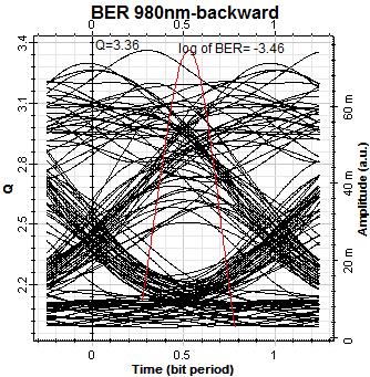
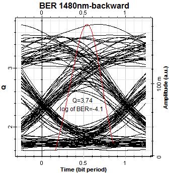
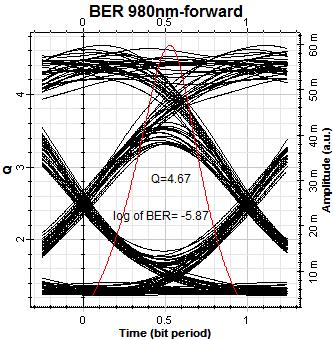
10 has high gain values, lies in the range of m and the forward structure gives better gain than the backward. For the same pumping wavelength, Fig. 8 exhibits the noise figure variation against the operating wavelength given that the fiber length is held constant at the same values as taken in Fig. 7. For backward pumping, we notice that the NF is approximately fixed for 5m length and this is the optimum value for the fiber length to achieve a minimum NF. As the length increases, the NF increases rapidly specially for lower wavelengths and fastly decayed as the wavelength increases. In the case of forward pumping, on the other hand, NF is approximately the same for the chosen lengths with minor variations. As a concluded remark, for the same parameter values, forward pumping gives lower NF as well as higher gain values, especially in the band around 1560 nm, in comparison with those obtained in the case of backward pumping. Figs. 9 & 10 repeat the same characteristics, as Figs. 7 & 8, for the EDFA device with the exception that the pumping wavelength is modified to become 1480 nm. In comparing the results drawn in these figures with those presented in the previous plots, one deduces that the pumping at 1480 nm gives higher gain values than that obtained by pumping at 980 nm. Additionally, lower NF is achieved in the case of 1480 nm than in the case of 980 nm when the two pumping wavelengths operate in backward configuration whilst the opposite is noticed in forward pumping configuration where 1480 nm provides higher NF than 980 nm given that the selected parameter values are kept unchanged in the two situations. Since the eye diagram is a useful tool for understanding signal impairments in the physical layer of high speed digital data systems, we use it here as a measure of the purity of the optical signal at the output of the EDFA amplifier. The eye diagram, Q-factor, and BER are drawn for different pumping wavelengths as well as several mechanisms of pumping for 20 m-edfa length. Fig. 11 and Table 1 represent a comparison of Q-factor, BER and eye height among the different configurations of pumping. The exhibited results demonstrate that the pumping at 1480 nm has better performance than that at 980 nm wavelength. Additionally, the 1480 nm forward pumping configuration has the highest performance whilst the backward pumping configuration gives the worst parameter values for BER, Q-factor, and eye diagram. Fig. 4. One-stage 980 nm backward pumping of 20 m EDFA length 10


11 Fig. 5. Gain spectrum at 980 nm and 1480 nm backward & forward & dual pump of 20 m EDFA length Fig. 6. Noise figure spectrum at 980 nm & 1480 nm backward & forward & dual pump of 20m EDFA length Table 1. Q-factor, BER and eye height for different configurations in one-stage-edfa EDFA Q-factor BER log of BER Eye height 980-backward * forward * dual * backward * forward * dual *

 of dual pumping configuration for the two interested pumping wavelengths as forward")


12 Fig. 7. Gain spectrum at 980 nm backward & forward pumping mechanisms for different lengths of EDFA device Fig. 8. NF spectrum at 980 nm backward & forward pumping mechanisms for different lengths of EDFA device The object of Fig. 12 is to make a comparison, from the gain and noise figure points of view, among the different combinations ( , , and ) of dual pumping configuration for the two interested pumping wavelengths as forward and backward. A big insight in the outlined results demonstrates that the obtained gain is nearly the same at different configurations and little high at pumping combination. For the NF performance, we noticed that it has its smallest value at pumping combination, comes next, then , and finally it attains its highest value at situation. En conclusion, it is seen that the gain is highest at case but the NF is lowest 12


13 Fig. 9. Gain spectrum at 1480 nm backward & forward pumping mechanisms for several lengths of EDFA system Fig. 10. NF spectrum at 1480 nm backward & forward pumping mechanisms for several lengths of EDFA system at situation, and the best configuration, for obtaining high gain and low noise figure, can be achieved through the configuration in which the 980 nm is chosen for forward pumping while the backward pumping is carried out at 1480 nm. 3.3 Double-stage EDFA The gain and noise figure of an EDFA device can be enhancement by using its double stage configuration. Therefore, we use two-stage EDFA device to benefice the maximum gain from 1480 nm as well as the minimum NF from 980 nm pumping wavelengths. By forward pumping the first stage at 980 nm and the second one at 1480 nm pump, we obtain the results that are displayed in Fig. 13. This figure illustrates that the gain and NF are improved as EDFA length is increased. Through the using of 13
14 small length for the first stage, we will get minimum NF, where NF decreases as the length of the first stage decreases. A maximum gain of 59.4 db and a minimum NF of db can be achieved by adjusting the first stage at 4 m- length and the second one at 15 m-length. Fig. 14 as well as Table 2 exhibits some numerical values of the Q-factor, Min log of BER and eye diagram for different lengths of twostage EDFA device. The examination of the shown results illustrates that the Q-factor and BER of different 2-stage-lengths are almost the same, but the best result (0.32) of eye height is obtained for 4 m-15 m combination of stage lengths. However, high gain and low NF are attained in the case of 4 m-20 m stage lengths with the drawback of low eye height in comparison with 4-15 m stage lengths situation. So, for best result of gain, NF and eye diagram, the situation of 4 m length for the first-stage and 15 m for the second-stage EDFA configuration can be adopted. 3.4 Three-stage EDFA In this situation of operating conditions, we constitute three-stage EDFA configuration in which the first stage is forward pumped at 980 nm wavelength whilst the second and third ones are supplied by 1480 nm pumping wavelength. Fig. 15 depicts a comparison between different 3-stage-lengths for gain and NF. The curves of this scene illustrate that the gain is increased as EDFA-length is increased. Additionally, by reducing the length of the first stage, the NF can be minimized, where the NF is decreased as first stage-length is decreased. Hence, a maximum gain (of 64.6 db) and a minimum NF (in the range db) can be realized by adjusting the lengths of the stages to become 4, 10, and 15 m for the first, second, and third stage, respectively. Fig. 16 and Table 3 display some numerical values for the more important parameters that distinguish one EDFA system over another. These parameters include Q, G, NF, and BER along with the eye-diagram. The underlined plot shows the variation of G and NF, as a function of the operating wavelength, for several lengths of the different stages of the EDFA device under examination, whilst the considered Table depicts, numerically, the underlined parameters in an explicit manner. The presented results demonstrate that the Q-factor and BER are almost the same and the best result (0.53) of eye height is attained in the case of 4 m-10 m-5 m stage lengths. On the other hand, high gain and low NF are accomplished through the combination of m for the stages of the EDFA optical amplifier. For achieving an EDFA system for which the gain, NF, and eye diagram are practically acceptable, the length of the first stage is chosen to be 4 m whilst the second and third stages are fixed at 10 m length. Table 2. Q-factor, BER and eye height for different double-stage EDFA system lengths EDFA-lengths Q-factor BER Eye height Max - min gain Max - min NF 5-5 m * m * m * m * m * m * m * m * m * m * Table 3. Q-factor, BER and eye height for different three-stage EDFA construction EDFA-lengths Q-factor BER Eye height Max - min gain Max - min NF m * m * m * m * m * m *
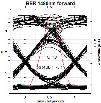
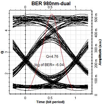
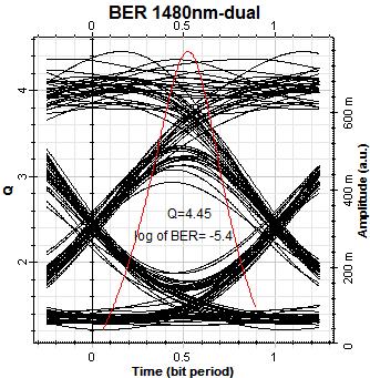
15 Fig. 11. Eye-diagram, Q-factor, and BER at 1480 nm backward & forward pump at 20 m-edfa length 15


![17. In this regard, four-stage 980 nm- backward pump EDFA of 5m-length each was used in [2] to obtain a maximum gain of 61.](/docs-images/90/104448085/images/16-3.jpg "04 db, a NF of (Min 3.9 db and max 5 db), an eye height of 0.44, and a BER of 6.65*10-7.")
16 Fig. 12. Comparison of gain and noise figure of dual pump configuration of 20 m-edfa device Fig. 13. Gain and noise figure spectrum of two-stage EDFA forward pumping at 0.75 W pump 3.5 Four-stage EDFA By using the software Optisystem, we can construct a four-stage EDFA system in the same manner as we have previously established in the single-stage version of the device under examination and the block diagram of the resulting system is exhibited in Fig. 17. In this regard, four-stage 980 nm- backward pump EDFA of 5m-length each was used in [2] to obtain a maximum gain of db, a NF of (Min 3.9 db and max 5 db), an eye height of 0.44, and a BER of 6.65*10-7. We can further increase the gain and decrease the NF in this arrangement of EDFA system through the use of different configuration of pumping as well as 16


17 varying the optical lengths of the selected stages. In this regard, we construct four-stage EDFA scheme with forward pumping; the first stage is pumped by 980 nm wavelength whilst the other three stages are pumped through 1480 nm wavelength. Fig. 18 illustrates the gain as well as NF spectrum for different constructions of 4-stage EDFA system. According to the curves of this plot, it is noted that we can get a maximum gain of 67.7 db and a minimum NF of 3.2 db by setting 4 m, 10 m, 10 m, and 15 m lengths for the first, second, third, and fourth stage of EDFA system, respectively. Fig. 14. Eye-diagram, Q-factor and BER of two-stage forward-pumping EDFA system Fig. 15. Gain and noise figure spectrum of three-stage EDFA forward pumping at 0.75 W pump 17
: 1-20, 2017;")


18 El-Mashade and Mohamed; BJAST, 19(4): 1-20, 2017; Article no.bjast Fig. 16. Eye-diagram, Q-factor and BER of three-stage forward-pumping EDFA Fig. 17. Four-stage 980 nm backward pumping of 20 m EDFA length 18


19 Fig. 18. Gain and noise figure spectrum of 4-stage EDFA device Fig. 19. Eye-diagram, Q-factor and BER of 4-stage EDFA system Table 4. Q-factor, BER and eye height for different lengths of four-stage EDFA scheme EDFA-lengths Q-factor BER Eye height Max - min gain Max - min NF m * m * m * m * m * Fig. 19 and Table 4 visualize a comparison of Q-factor, Min log of BER along with the eye diagram of different 4-stage EDFA arrangements. It is shown that the Q-factor and BER are almost the same for all the tested combinations. However, the best result (0.66) of eye height is carried out through the stage lengths of m, whilst the high gain and 19
20 low NF are fulfilled by choosing stage lengths of m for the EDFA mechanism. So, the best values of gain, NF, and eye diagram can be accomplished through the use of four-stage EDFA system with stage lengths of 4 m-10 m-5 m-10 m or 4 m-10 m-10 m-8 m. 4. CONCLUSIONS We have characterized and simulated the performance of EDFA device using pumping source of 980 nm and 1480 nm wavelengths. The calculated results were discussed and compared with the object of searching the optimum parameter values for each situation of multi-stage construction of EDFA system. It is of importance to attain the desired range of wavelengths in which the EDFA system provides efficient results. Along with the source wavelength, other parameters like length, pump power, and signal power are changed in such a way that the optimized values of gain and noise figure are recorded with the aid of software Optisystem. Additionally, a comparison was made among the three pumping configurations, forward, backward, and bidirectional at different pump power levels. By analyzing the gain and noise figure spectrums of the EDFA under different pump powers, it was concluded that the pump power of 750 mw gives the most favorable results. For such case of power level, 1480 nm pumping wavelength gives the maximum gain whilst 980 nm forward pumping leads to minimum NF. So, to enhance the gain and NF, the best possible construction of EDFA system is to use 980 nm forward pumping as first stage and 1480 nm pumping for other additional stages. As a general concluded remark, the EDFA features good gain flatness, low noise figure, and wide operating wavelength range along with its ability to good network control interface. COMPETING INTERESTS REFERENCES 1. Shukla MP, Kaur KP. Performance analysis of EDFA for different pumping configurations at high data rate. Global Journal of Researches in Engineering Electrical and Electronics Engineering. 2013;13(9) version 1.0: Kumar G, Sadhu I, Sangeetha N. Gain and noise figure analysis of erbium doped fiber amplifier by four stage enhancement and analysis. International Journal of Scientific and Research Publications. 2014;4(4): Gujral J, Goel V. Analysis of augmented gain EDFA systems using single and multi-wavelength sources. International Journal of Computer Applications. 2012;47(4): Kaur U. Performance analysis of transient aspects for EDFA amplifiers. MSc Thesis, Thapar Institute of Engineering and Technology, Deemed University, Patiala; Venkataramanan V. Optical ampalifiers. Institute for Optical Sciences, University of Toronto, Lecture Notes. 6. Jiang C, Zeng Q, Liu H, Tang X, Yang X. Advance in optical fiber amplifier. In Rare- Earth-Doped Materials and Devices IV, Shibin Jiang, Proceedings of SPIE. 2000;3942: Govind P Agrawal. Fiber-Optic communication systems. John Wiley & Sons, Inc., Publication; Sharma KK, Sharma V, Sharma B. Analysis of 2-stage erbium doped fibre amplifier with optimum parameters. IJEE. 2013;5(2): Chen P, Feng S, An L, Song H, Zhao X, Xu C. Crystal fiber based erbium doped amplifiers and their gain. International Journal of Future Computer and Communication. 2012;1(1): Authors have declared that no competing interests exist El-Mashade and Mohamed; This is an Open Access article distributed under the terms of the Creative Commons Attribution License ( which permits unrestricted use, distribution, and reproduction in any medium, provided the original work is properly cited. Peer-review history: The peer review history for this paper can be accessed here: 20
Performance analysis of Erbium Doped Fiber Amplifier at different pumping configurations
 Performance analysis of Erbium Doped Fiber Amplifier at different pumping configurations Mayur Date M.E. Scholar Department of Electronics and Communication Ujjain Engineering College, Ujjain (M.P.) datemayur3@gmail.com
Performance Analysis of EDFA for Different Pumping Configurations at High Data Rate
 Global Journal of Researches in Engineering Electrical and Electronics Engineering Volume 13 Issue 9 Version 1.0 Year 2013 Type: Double Blind Peer Reviewed International Research Journal Publisher: Global
Optical Fibre Amplifiers Continued
 1 Optical Fibre Amplifiers Continued Stavros Iezekiel Department of Electrical and Computer Engineering University of Cyprus ECE 445 Lecture 09 Fall Semester 2016 2 ERBIUM-DOPED FIBRE AMPLIFIERS BASIC
Optical Amplifiers Photonics and Integrated Optics (ELEC-E3240) Zhipei Sun Photonics Group Department of Micro- and Nanosciences Aalto University
 Zhipei Sun Photonics Group Department of Micro- and Nanosciences Aalto University") Photonics Group Department of Micro- and Nanosciences Aalto University Optical Amplifiers Photonics and Integrated Optics (ELEC-E3240) Zhipei Sun Last Lecture Topics Course introduction Ray optics & optical
Photonics Group Department of Micro- and Nanosciences Aalto University Optical Amplifiers Photonics and Integrated Optics (ELEC-E3240) Zhipei Sun Last Lecture Topics Course introduction Ray optics & optical
Advanced Optical Communications Prof. R. K. Shevgaonkar Department of Electrical Engineering Indian Institute of Technology, Bombay
 Advanced Optical Communications Prof. R. K. Shevgaonkar Department of Electrical Engineering Indian Institute of Technology, Bombay Lecture No. # 27 EDFA In the last lecture, we talked about wavelength
Chapter 12: Optical Amplifiers: Erbium Doped Fiber Amplifiers (EDFAs)
") Chapter 12: Optical Amplifiers: Erbium Doped Fiber Amplifiers (EDFAs) Prof. Dr. Yaocheng SHI ( 时尧成 ) yaocheng@zju.edu.cn http://mypage.zju.edu.cn/yaocheng 1 Traditional Optical Communication System Loss
Chapter 12: Optical Amplifiers: Erbium Doped Fiber Amplifiers (EDFAs) Prof. Dr. Yaocheng SHI ( 时尧成 ) yaocheng@zju.edu.cn http://mypage.zju.edu.cn/yaocheng 1 Traditional Optical Communication System Loss
Chapter 8. Wavelength-Division Multiplexing (WDM) Part II: Amplifiers
 Part II: Amplifiers") Chapter 8 Wavelength-Division Multiplexing (WDM) Part II: Amplifiers Introduction Traditionally, when setting up an optical link, one formulates a power budget and adds repeaters when the path loss exceeds
Chapter 8 Wavelength-Division Multiplexing (WDM) Part II: Amplifiers Introduction Traditionally, when setting up an optical link, one formulates a power budget and adds repeaters when the path loss exceeds
Fiberoptic Communication Systems By Dr. M H Zaidi. Optical Amplifiers
 Optical Amplifiers Optical Amplifiers Optical signal propagating in fiber suffers attenuation Optical power level of a signal must be periodically conditioned Optical amplifiers are a key component in
S-band gain-clamped grating-based erbiumdoped fiber amplifier by forward optical feedback technique
 S-band gain-clamped grating-based erbiumdoped fiber amplifier by forward optical feedback technique Chien-Hung Yeh 1, *, Ming-Ching Lin 3, Ting-Tsan Huang 2, Kuei-Chu Hsu 2 Cheng-Hao Ko 2, and Sien Chi
EDFA-WDM Optical Network Analysis
 EDFA-WDM Optical Network Analysis Narruvala Lokesh, kranthi Kumar Katam,Prof. Jabeena A Vellore Institute of Technology VIT University, Vellore, India Abstract : Optical network that apply wavelength division
EDFA WDM Optical Network using GFF
 EDFA WDM Optical Network using GFF Shweta Bharti M. Tech, Digital Communication, (Govt. Women Engg. College, Ajmer), Rajasthan, India ABSTRACT This paper describes the model and simulation of EDFA WDM
Performance Analysis of WDM Network Based On EDFA Amplifier with Different Pumping Techniques
 Performance Analysis of WDM Network Based On EDFA Amplifier with Different Pumping Techniques Varsha Honde* varshahonde@gmail.com* Anuja Mhatre anujamhatre93@yahoo.com Sourabh Tonde sourabhtonde2511@gmail.com
Erbium-Doper Fiber Amplifiers
 Seminar presentation Erbium-Doper Fiber Amplifiers 27.11.2009 Ville Pale Presentation Outline History of EDFA EDFA operating principle Stimulated Emission Stark Splitting Gain Gain flatness Gain Saturation
Performance Analysis of Designing a Hybrid Optical Amplifier (HOA) for 32 DWDM Channels in L-band by using EDFA and Raman Amplifier
 for 32 DWDM Channels in L-band by using EDFA and Raman Amplifier") Performance Analysis of Designing a Hybrid Optical Amplifier (HOA) for 32 DWDM Channels in L-band by using EDFA and Raman Amplifier Aied K. Mohammed, PhD Department of Electrical Engineering, University
Performance Analysis of Designing a Hybrid Optical Amplifier (HOA) for 32 DWDM Channels in L-band by using EDFA and Raman Amplifier Aied K. Mohammed, PhD Department of Electrical Engineering, University
ESTIMATION OF NOISE FIGURE USING GFF WITH HYBRID QUAD PUMPING
 IJCRR Vol 05 issue 13 Section: Technology Category: Research Received on: 19/12/12 Revised on: 16/01/13 Accepted on: 09/02/13 ESTIMATION OF NOISE FIGURE USING GFF WITH HYBRID QUAD PUMPING V.R. Prakash,
Gain Flattening Improvements With Two Cascade Erbium Doped Fiber Amplifier In WDM Systems
 International Academic Institute for Science and Technology International Academic Journal of Science and Engineering Vol. 3, No. 1, 2016, pp. 36-42. ISSN 2454-3896 International Academic Journal of Science
PERFORMANCE ANALYSIS OF WDM AND EDFA IN C-BAND FOR OPTICAL COMMUNICATION SYSTEM
 www.arpapress.com/volumes/vol13issue1/ijrras_13_1_26.pdf PERFORMANCE ANALYSIS OF WDM AND EDFA IN C-BAND FOR OPTICAL COMMUNICATION SYSTEM M.M. Ismail, M.A. Othman, H.A. Sulaiman, M.H. Misran & M.A. Meor
EDFA-WDM Optical Network Design System
 Available online at www.sciencedirect.com Procedia Engineering 53 ( 2013 ) 294 302 Malaysian Technical Universities Conference on Engineering & Technology 2012, MUCET 2012 Part -1 Electronic and Electrical
Analysis of Gain and NF using Raman and hybrid RFA-EDFA
 Analysis of Gain and NF using Raman and hybrid RFA-EDFA Abdallah M. Hassan 1, Ashraf Aboshosha 2, Mohamed B. El_Mashade 3 Electrical Engineering Dept., Faculty of Engineering, Al-Azhar University, Nasr
Optical Fiber Amplifiers. Scott Freese. Physics May 2008
 Optical Fiber Amplifiers Scott Freese Physics 262 2 May 2008 Partner: Jared Maxson Abstract The primary goal of this experiment was to gain an understanding of the basic components of an Erbium doped fiber
Photonics and Optical Communication Spring 2005
 Photonics and Optical Communication Spring 2005 Final Exam Instructor: Dr. Dietmar Knipp, Assistant Professor of Electrical Engineering Name: Mat. -Nr.: Guidelines: Duration of the Final Exam: 2 hour You
Introduction Fundamental of optical amplifiers Types of optical amplifiers
 ECE 6323 Introduction Fundamental of optical amplifiers Types of optical amplifiers Erbium-doped fiber amplifiers Semiconductor optical amplifier Others: stimulated Raman, optical parametric Advanced application:
Investigation of Performance Analysis of EDFA Amplifier. Using Different Pump Wavelengths and Powers
 Investigation of Performance Analysis of EDFA Amplifier Using Different Pump Wavelengths and Powers Ramandeep Kaur, Parkirti, Rajandeep Singh ABSTRACT In this paper, an investigation of the performance
FIBER OPTICS. Prof. R.K. Shevgaonkar. Department of Electrical Engineering. Indian Institute of Technology, Bombay. Lecture: 37
 FIBER OPTICS Prof. R.K. Shevgaonkar Department of Electrical Engineering Indian Institute of Technology, Bombay Lecture: 37 Introduction to Raman Amplifiers Fiber Optics, Prof. R.K. Shevgaonkar, Dept.
Optical Communications and Networking 朱祖勍. Oct. 9, 2017
 Optical Communications and Networking Oct. 9, 2017 1 Optical Amplifiers In optical communication systems, the optical signal from the transmitter are attenuated by the fiber and other passive components
FIBER OPTICS. Prof. R.K. Shevgaonkar. Department of Electrical Engineering. Indian Institute of Technology, Bombay. Lecture: 26
 FIBER OPTICS Prof. R.K. Shevgaonkar Department of Electrical Engineering Indian Institute of Technology, Bombay Lecture: 26 Wavelength Division Multiplexed (WDM) Systems Fiber Optics, Prof. R.K. Shevgaonkar,
Research Article Output Signal Power Analysis in Erbium-Doped Fiber Amplifier with Pump Power and Length Variation Using Various Pumping Techniques
 ISRN Electronics Volume 213, Article ID 31277, 6 pages http://dx.doi.org/1.1155/213/31277 Research Article Output Signal Power Analysis in Erbium-Doped Fiber Amplifier with Power and Length Variation Using
Design Coordination of Pre-amp EDFAs and PIN Photon Detectors For Use in Telecommunications Optical Receivers
 Paper 010, ENT 201 Design Coordination of Pre-amp EDFAs and PIN Photon Detectors For Use in Telecommunications Optical Receivers Akram Abu-aisheh, Hisham Alnajjar University of Hartford abuaisheh@hartford.edu,
Chirped Bragg Grating Dispersion Compensation in Dense Wavelength Division Multiplexing Optical Long-Haul Networks
 363 Chirped Bragg Grating Dispersion Compensation in Dense Wavelength Division Multiplexing Optical Long-Haul Networks CHAOUI Fahd 3, HAJAJI Anas 1, AGHZOUT Otman 2,4, CHAKKOUR Mounia 3, EL YAKHLOUFI Mounir
PERFORMANCE ANALYSIS OF 4 CHANNEL WDM_EDFA SYSTEM WITH GAIN EQUALISATION
 PERFORMANCE ANALYSIS OF 4 CHANNEL WDM_EDFA SYSTEM WITH GAIN EQUALISATION S.Hemalatha 1, M.Methini 2 M.E.Student, Department Of ECE, Sri Sairam Engineering College,Chennai,India1 Assistant professsor,department
Performance Analysis of 4-Channel WDM System with and without EDFA
 Performance Analysis of 4-Channel WDM System with and without EDFA 1 Jyoti Gujral, 2 Maninder Singh 1,2 Indo Global College of Engineering, Abhipur, Mohali, Punjab, India Abstract The Scope of this paper
DESIGN TEMPLATE ISSUES ANALYSIS FOR ROBUST DESIGN OUTPUT. performance, yield, reliability
 DESIGN TEMPLATE ISSUES performance, yield, reliability ANALYSIS FOR ROBUST DESIGN properties, figure-of-merit thermodynamics, kinetics, process margins process control OUTPUT models, options Optical Amplification
AN EFFICIENT L-BAND ERBIUM-DOPED FIBER AMPLIFIER WITH ZIRCONIA-YTTRIA-ALUMINUM CO-DOPED SILICA FIBER
 Journal of Non - Oxide Glasses Vol. 10, No. 3, July - September 2018, p. 65-70 AN EFFICIENT L-BAND ERBIUM-DOPED FIBER AMPLIFIER WITH ZIRCONIA-YTTRIA-ALUMINUM CO-DOPED SILICA FIBER A. A. ALMUKHTAR a, A.
Performance of Digital Optical Communication Link: Effect of In-Line EDFA Parameters
 PCS-7 766 CSDSP 00 Performance of Digital Optical Communication Link: Effect of n-line EDFA Parameters Ahmed A. Elkomy, Moustafa H. Aly, Member of SOA, W. P. g 3, Senior Member, EEE, Z. Ghassemlooy 3,
Gain Flattened L-Band EDFA -Raman Hybrid Amplifier by Bidirectional Pumping technique
 Gain Flattened L-Band EDFA -Raman Hybrid Amplifier by Bidirectional Pumping technique Avneet Kour 1, Neena Gupta 2 1,2 Electronics and Communication Department, PEC University of Technology, Chandigarh
ANALYSIS OF THE CROSSTALK IN OPTICAL AMPLIFIERS
 MANDEEP SINGH AND S K RAGHUWANSHI: ANALYSIS OF THE CROSSTALK IN OPTICAL AMPLIFIERS DOI: 10.1917/ijct.013.0106 ANALYSIS OF THE CROSSTALK IN OPTICAL AMPLIFIERS Mandeep Singh 1 and S. K. Raghuwanshi 1 Department
is a method of transmitting information from one place to another by sending light through an optical fiber. The light forms an electromagnetic
 is a method of transmitting information from one place to another by sending light through an optical fiber. The light forms an electromagnetic carrier wave that is modulated to carry information. The
Performance Limitations of WDM Optical Transmission System Due to Cross-Phase Modulation in Presence of Chromatic Dispersion
 Performance Limitations of WDM Optical Transmission System Due to Cross-Phase Modulation in Presence of Chromatic Dispersion M. A. Khayer Azad and M. S. Islam Institute of Information and Communication
Multi-wavelength laser generation with Bismuthbased Erbium-doped fiber
 Multi-wavelength laser generation with Bismuthbased Erbium-doped fiber H. Ahmad 1, S. Shahi 1 and S. W. Harun 1,2* 1 Photonics Research Center, University of Malaya, 50603 Kuala Lumpur, Malaysia 2 Department
International Journal of Advanced Research in Computer Science and Software Engineering
 ISSN: 2277 128X International Journal of Advanced Research in Computer Science and Software Engineering Research Paper Available online at: Performance Analysis of WDM/SCM System Using EDFA Mukesh Kumar
To investigate effects of extinction ratio on SOA based wavelength Converters for all Optical Networks
 289 To investigate effects of extinction ratio on SOA based wavelength Converters for all Optical Networks Areet Aulakh 1, Kulwinder Singh Malhi 2 1 Student, M.Tech, ECE department, Punjabi University,
Overview Of EDFA for the Efficient Performance Analysis
 IOSR Journal of Engineering (IOSRJEN) ISSN (e): 2250-3021, ISSN (p): 2278-8719 Vol. 04, Issue 03 (March. 2014), V4 PP 01-08 www.iosrjen.org Overview Of EDFA for the Efficient Performance Analysis Anuja
International Association of Scientific Innovation and Research (IASIR) (An Association Unifying the Sciences, Engineering, and Applied Research)
 (An Association Unifying the Sciences, Engineering, and Applied Research)") International Association of Scientific Innovation and Research (IASIR) (An Association Unifying the Sciences, Engineering, and Applied Research) International Journal of Emerging Technologies in Computational
International Association of Scientific Innovation and Research (IASIR) (An Association Unifying the Sciences, Engineering, and Applied Research) International Journal of Emerging Technologies in Computational
Ultra High Capacity Wavelength Division Multiplexed Optical Wireless Communication System
 Ultra High Capacity Wavelength Division Multiplexed Optical Wireless Communication System 1 Meenakshi, 2 Gurinder Singh 1 Student, 2 Assistant Professor 1 Electronics and communication, 1 Ludhiana College
Basic concepts. Optical Sources (b) Optical Sources (a) Requirements for light sources (b) Requirements for light sources (a)
 Optical Sources (a) Requirements for light sources (b) Requirements for light sources (a)") Optical Sources (a) Optical Sources (b) The main light sources used with fibre optic systems are: Light-emitting diodes (LEDs) Semiconductor lasers (diode lasers) Fibre laser and other compact solid-state
Optical Sources (a) Optical Sources (b) The main light sources used with fibre optic systems are: Light-emitting diodes (LEDs) Semiconductor lasers (diode lasers) Fibre laser and other compact solid-state
Optical Amplifiers. Continued. Photonic Network By Dr. M H Zaidi
 Optical Amplifiers Continued EDFA Multi Stage Designs 1st Active Stage Co-pumped 2nd Active Stage Counter-pumped Input Signal Er 3+ Doped Fiber Er 3+ Doped Fiber Output Signal Optical Isolator Optical
Study of Multiwavelength Fiber Laser in a Highly Nonlinear Fiber
 Study of Multiwavelength Fiber Laser in a Highly Nonlinear Fiber I. H. M. Nadzar 1 and N. A.Awang 1* 1 Faculty of Science, Technology and Human Development, Universiti Tun Hussein Onn Malaysia, Johor,
The Report of Gain Performance Characteristics of the Erbium Doped Fiber Amplifier (EDFA)
") The Report of Gain Performance Characteristics of the Erbium Doped Fiber Amplifier (EDFA) Masruri Masruri (186520) 22/05/2008 1 Laboratory Setup The laboratory setup using in this laboratory experiment
The Report of Gain Performance Characteristics of the Erbium Doped Fiber Amplifier (EDFA) Masruri Masruri (186520) 22/05/2008 1 Laboratory Setup The laboratory setup using in this laboratory experiment
RZ BASED DISPERSION COMPENSATION TECHNIQUE IN DWDM SYSTEM FOR BROADBAND SPECTRUM
 RZ BASED DISPERSION COMPENSATION TECHNIQUE IN DWDM SYSTEM FOR BROADBAND SPECTRUM Prof. Muthumani 1, Mr. Ayyanar 2 1 Professor and HOD, 2 UG Student, Department of Electronics and Communication Engineering,
OBSERVATION AND MITIGATION OF POWER TRANSIENTS IN 160Gbps OPTICAL BACKHAUL NETWORKS
 OBSERVATION AND MITIGATION OF POWER TRANSIENTS IN 160Gbps OPTICAL BACKHAUL NETWORKS Vikrant Sharma Anurag Sharma Electronics and Communication Engineering, CT Group of Institutions, Jalandhar Dalveer Kaur
A Novel Design Technique for 32-Channel DWDM system with Hybrid Amplifier and DCF
 Research Manuscript Title A Novel Design Technique for 32-Channel DWDM system with Hybrid Amplifier and DCF Dr.Punal M.Arabi, Nija.P.S PG Scholar, Professor, Department of ECE, SNS College of Technology,
Design of an Optical Submarine Network With Longer Range And Higher Bandwidth
 Design of an Optical Submarine Network With Longer Range And Higher Bandwidth Yashas Joshi 1, Smridh Malhotra 2 1,2School of Electronics Engineering (SENSE) Vellore Institute of Technology Vellore, India
EDFA SIMULINK MODEL FOR ANALYZING GAIN SPECTRUM AND ASE. Stephen Z. Pinter
 EDFA SIMULINK MODEL FOR ANALYZING GAIN SPECTRUM AND ASE Stephen Z. Pinter Ryerson University Department of Electrical and Computer Engineering spinter@ee.ryerson.ca December, 2003 ABSTRACT A Simulink model
Available online at ScienceDirect. Procedia Computer Science 93 (2016 )
") Available online at www.sciencedirect.com ScienceDirect Procedia Computer Science 93 (016 ) 647 654 6th International Conference On Advances In Computing & Communications, ICACC 016, 6-8 September 016,
Available online at www.sciencedirect.com ScienceDirect Procedia Computer Science 93 (016 ) 647 654 6th International Conference On Advances In Computing & Communications, ICACC 016, 6-8 September 016,
Performance Evaluation of 32 Channel DWDM System Using Dispersion Compensation Unit at Different Bit Rates
 Performance Evaluation of 32 Channel DWDM System Using Dispersion Compensation Unit at Different Bit Rates Simarpreet Kaur Gill 1, Gurinder Kaur 2 1Mtech Student, ECE Department, Rayat- Bahra University,
Spectral Response of FWM in EDFA for Long-haul Optical Communication
 Spectral Response of FWM in EDFA for Long-haul Optical Communication Lekshmi.S.R 1, Sindhu.N 2 1 P.G.Scholar, Govt. Engineering College, Wayanad, Kerala, India 2 Assistant Professor, Govt. Engineering
Optical Fiber Amplifiers
 Optical Fiber Amplifiers Yousif Ahmed Omer 1 and Dr. Hala Eldaw Idris 2 1,2 Department of communication Faculty of Engineering, AL-Neelain University, Khartoum, Sudan Publishing Date: June 15, 2016 Abstract
Analysis and Review of EDFA
 918 Analysis and Review of EDFA 1 Dipika Pradhan, 2 Vivekanand Mishra 1, 2 Department of Electronics and Communication Engineering, S. V. National Institute of Technology Surat, India Abstract - Optical
OPTI510R: Photonics. Khanh Kieu College of Optical Sciences, University of Arizona Meinel building R.626
 OPTI510R: Photonics Khanh Kieu College of Optical Sciences, University of Arizona kkieu@optics.arizona.edu Meinel building R.626 Announcements HW #5 is assigned (due April 9) April 9 th class will be in
Photonics and Optical Communication
 Photonics and Optical Communication (Course Number 300352) Spring 2007 Dr. Dietmar Knipp Assistant Professor of Electrical Engineering http://www.faculty.iu-bremen.de/dknipp/ 1 Photonics and Optical Communication
International Journal of Computational Intelligence and Informatics, Vol. 2: No. 4, January - March Bandwidth of 13GHz
 Simulation and Analysis of GFF at WDM Mux Bandwidth of 13GHz Warsha Balani Department of ECE, BIST Bhopal, India balani.warsha@gmail.com Manish Saxena Department of ECE,BIST Bhopal, India manish.saxena2008@gmail.com
Effect of ASE on Performance of EDFA for 1479nm-1555nm Wavelength Range
 Effect of ASE on Performance of EDFA for 1479nm-1555nm Wavelength Range Inderpreet Kaur, Neena Gupta Deptt. of Electrical & Electronics Engg. Chandigarh University Gharuan, India Dept. of Electronics &
Phase Modulator for Higher Order Dispersion Compensation in Optical OFDM System
 Phase Modulator for Higher Order Dispersion Compensation in Optical OFDM System Manpreet Singh 1, Karamjit Kaur 2 Student, University College of Engineering, Punjabi University, Patiala, India 1. Assistant
Optical Fiber Communication
 A Seminar report On Optical Fiber Communication Submitted in partial fulfillment of the requirement for the award of degree Of Mechanical SUBMITTED TO: www.studymafia.org SUBMITTED BY: www.studymafia.org
Gain-clamping techniques in two-stage double-pass L-band EDFA
 PRAMANA c Indian Academy of Sciences Vol. 66, No. 3 journal of March 2006 physics pp. 539 545 Gain-clamping techniques in two-stage double-pass L-band EDFA S W HARUN 1, N Md SAMSURI 2 and H AHMAD 2 1 Faculty
DESIGN AND CHARACTERIZATION OF HIGH PERFORMANCE C AND L BAND ERBIUM DOPED FIBER AMPLIFIERS (C,L-EDFAs)
") DESIGN AND CHARACTERIZATION OF HIGH PERFORMANCE C AND L BAND ERBIUM DOPED FIBER AMPLIFIERS (C,L-EDFAs) Ahmet Altuncu Arif Başgümüş Burçin Uzunca Ekim Haznedaroğlu e-mail: altuncu@dumlupinar.edu.tr e-mail:
DESIGN AND CHARACTERIZATION OF HIGH PERFORMANCE C AND L BAND ERBIUM DOPED FIBER AMPLIFIERS (C,L-EDFAs) Ahmet Altuncu Arif Başgümüş Burçin Uzunca Ekim Haznedaroğlu e-mail: altuncu@dumlupinar.edu.tr e-mail:
Comparative Analysis of Various Optimization Methodologies for WDM System using OptiSystem
 Comparative Analysis of Various Optimization Methodologies for WDM System using OptiSystem Koushik Mukherjee * Department of Electronics and Communication, Dublin Institute of Technology, Ireland E-mail:
Performance Evaluation of Hybrid (Raman+EDFA) Optical Amplifiers in Dense Wavelength Division Multiplexed Optical Transmission System
 Optical Amplifiers in Dense Wavelength Division Multiplexed Optical Transmission System") Performance Evaluation of Hybrid (Raman+EDFA) Optical Amplifiers in Dense Wavelength Division Multiplexed Optical Transmission System Gagandeep Singh Walia 1, Kulwinder Singh 2, Manjit Singh Bhamrah 3
Performance Evaluation of Hybrid (Raman+EDFA) Optical Amplifiers in Dense Wavelength Division Multiplexed Optical Transmission System Gagandeep Singh Walia 1, Kulwinder Singh 2, Manjit Singh Bhamrah 3
Analysis of four channel CWDM Transceiver Modules based on Extinction Ratio and with the use of EDFA
 Analysis of four channel CWDM Transceiver Modules based on Extinction Ratio and with the use of EDFA P.P. Hema [1], Prof. A.Sangeetha [2] School of Electronics Engineering [SENSE], VIT University, Vellore
PERFORMANCE ANALYSIS OF OPTICAL TRANSMISSION SYSTEM USING FBG AND BESSEL FILTERS
 PERFORMANCE ANALYSIS OF OPTICAL TRANSMISSION SYSTEM USING FBG AND BESSEL FILTERS Antony J. S., Jacob Stephen and Aarthi G. ECE Department, School of Electronics Engineering, VIT University, Vellore, Tamil
Practical Aspects of Raman Amplifier
 Practical Aspects of Raman Amplifier Contents Introduction Background Information Common Types of Raman Amplifiers Principle Theory of Raman Gain Noise Sources Related Information Introduction This document
O. Mahran 1,2 and A.A.Samir 1
 International Journal of Scientific & Engineering Research, Volume 6, Issue 1, January-2015 1306 The Effect of the Amplifier Length on the Gain and Noise Figure of the Er/Yb Co-Doped Waveguide Amplifiers
Notes on Optical Amplifiers
 Notes on Optical Amplifiers Optical amplifiers typically use energy transitions such as those in atomic media or electron/hole recombination in semiconductors. In optical amplifiers that use semiconductor
Progress In Electromagnetics Research C, Vol. 15, 37 48, 2010 TEMPERATURE INSENSITIVE BROAD AND FLAT GAIN C-BAND EDFA BASED ON MACRO-BENDING
 Progress In Electromagnetics Research C, Vol. 15, 37 48, 2010 TEMPERATURE INSENSITIVE BROAD AND FLAT GAIN C-BAND EDFA BASED ON MACRO-BENDING P. Hajireza Optical Fiber Devices Group Multimedia University
Absorption: in an OF, the loss of Optical power, resulting from conversion of that power into heat.
 Absorption: in an OF, the loss of Optical power, resulting from conversion of that power into heat. Scattering: The changes in direction of light confined within an OF, occurring due to imperfection in
TECHNICAL ARTICLE: DESIGN BRIEF FOR INDUSTRIAL FIBRE OPTICAL NETWORKS
 TECHNICAL ARTICLE: DESIGN BRIEF FOR INDUSTRIAL FIBRE OPTICAL NETWORKS Designing and implementing a fibre optical based communication network intended to replace or augment an existing communication network
Performance Analysis of dispersion compensation using Fiber Bragg Grating (FBG) in Optical Communication
 in Optical Communication") Research Article International Journal of Current Engineering and Technology E-ISSN 2277 416, P-ISSN 2347-5161 214 INPRESSCO, All Rights Reserved Available at http://inpressco.com/category/ijcet Performance
Research Article International Journal of Current Engineering and Technology E-ISSN 2277 416, P-ISSN 2347-5161 214 INPRESSCO, All Rights Reserved Available at http://inpressco.com/category/ijcet Performance
New pumping scheme for high gain and low noise figure in an erbium-doped fiber amplifier
 New pumping scheme for high gain and low noise figure in an erbium-doped fiber amplifier V. Sinivasagam, 1,3a) Mustafa A. G. Abushagur, 1,2 K. Dimyati, 3 and F. Tumiran 1 1 Photronix (M) Sdn. Bhd., G05,
Examination Optoelectronic Communication Technology. April 11, Name: Student ID number: OCT1 1: OCT 2: OCT 3: OCT 4: Total: Grade:
 Examination Optoelectronic Communication Technology April, 26 Name: Student ID number: OCT : OCT 2: OCT 3: OCT 4: Total: Grade: Declaration of Consent I hereby agree to have my exam results published on
Application Instruction 001. The Enhanced Functionalities of Semiconductor Optical Amplifiers and their Role in Advanced Optical Networking
 The Enhanced Functionalities of Semiconductor Optical Amplifiers and their Role in Advanced Optical Networking I. Introduction II. III. IV. SOA Fundamentals Wavelength Conversion based on SOAs The Role
Elements of Optical Networking
 Bruckner Elements of Optical Networking Basics and practice of optical data communication With 217 Figures, 13 Tables and 93 Exercises Translated by Patricia Joliet VIEWEG+ TEUBNER VII Content Preface
Optical Amplifiers (Chapter 6)
") Optical Amplifiers (Chapter 6) General optical amplifier theory Semiconductor Optical Amplifier (SOA) Raman Amplifiers Erbium-doped Fiber Amplifiers (EDFA) Read Chapter 6, pp. 226-266 Loss & dispersion
Optical Amplifiers (Chapter 6) General optical amplifier theory Semiconductor Optical Amplifier (SOA) Raman Amplifiers Erbium-doped Fiber Amplifiers (EDFA) Read Chapter 6, pp. 226-266 Loss & dispersion
Performance Comparison of Pre-, Post-, and Symmetrical Dispersion Compensation for 96 x 40 Gb/s DWDM System using DCF
 Performance Comparison of Pre-, Post-, and Symmetrical Dispersion Compensation for 96 x 40 Gb/s DWDM System using Sabina #1, Manpreet Kaur *2 # M.Tech(Scholar) & Department of Electronics & Communication
A novel 3-stage structure for a low-noise, high-gain and gain-flattened L-band erbium doped fiber amplifier *
 Journal of Zhejiang University SCIENCE ISSN 9-9 http://www.zju.edu.cn/jzus E-mail: jzus@zju.edu.cn A novel -stage structure for a low-noise, high-gain and gain-flattened L-band erbium doped fiber amplifier
Optical systems have carrier frequencies of ~100 THz. This corresponds to wavelengths from µm.
 Introduction A communication system transmits information form one place to another. This could be from one building to another or across the ocean(s). Many systems use an EM carrier wave to transmit information.
Wideband Rare-earth-doped Fiber Amplification Technologies Gain Bandwidth Expansion in the C and L bands
 Wideband Rare-earth-doped Fiber Amplification Technologies Gain Bandwidth Expansion in the C and L bands Tadashi Sakamoto, Atsushi Mori, Hiroji Masuda, and Hirotaka Ono Abstract We are expanding the gain
UNIT-II : SIGNAL DEGRADATION IN OPTICAL FIBERS
 UNIT-II : SIGNAL DEGRADATION IN OPTICAL FIBERS The Signal Transmitting through the fiber is degraded by two mechanisms. i) Attenuation ii) Dispersion Both are important to determine the transmission characteristics
Study of All-Optical Wavelength Conversion and Regeneration Subsystems for use in Wavelength Division Multiplexing (WDM) Telecommunication Networks.
 Telecommunication Networks.") Study of All-Optical Wavelength Conversion and Regeneration Subsystems for use in Wavelength Division Multiplexing (WDM) Telecommunication Networks. Hercules Simos * National and Kapodistrian University
Study of All-Optical Wavelength Conversion and Regeneration Subsystems for use in Wavelength Division Multiplexing (WDM) Telecommunication Networks. Hercules Simos * National and Kapodistrian University
Contents for this Presentation. Multi-Service Transport
 Contents for this Presentation SDH/DWDM based Multi-Service Transport Platform by Khurram Shahzad ad Brief Contents Description for this of Presentation the Project Development of a Unified Transport Platform
Performance Evaluation of Different Hybrid Optical Amplifiers for 64 10, and Gbps DWDM transmission system
 Performance Evaluation of Different Hybrid Optical Amplifiers for 64 10, 96 10 and 128 10 Gbps DWDM transmission system Rashmi a, Anurag Sharma b, Vikrant Sharma c a Deptt. of Electronics & Communication
Power penalty caused by Stimulated Raman Scattering in WDM Systems
 Paper Power penalty caused by Stimulated Raman Scattering in WDM Systems Sławomir Pietrzyk, Waldemar Szczęsny, and Marian Marciniak Abstract In this paper we present results of an investigation into the
Chapter 9 GUIDED WAVE OPTICS
 [Reading Assignment, Hecht 5.6] Chapter 9 GUIDED WAVE OPTICS Optical fibers The step index circular waveguide is the most common fiber design for optical communications plastic coating (sheath) core cladding
S Optical Networks Course Lecture 2: Essential Building Blocks
 S-72.3340 Optical Networks Course Lecture 2: Essential Building Blocks Edward Mutafungwa Communications Laboratory, Helsinki University of Technology, P. O. Box 2300, FIN-02015 TKK, Finland Tel: +358 9
Current Trends in Unrepeatered Systems
 Current Trends in Unrepeatered Systems Wayne Pelouch (Xtera, Inc.) Email: wayne.pelouch@xtera.com Xtera, Inc. 500 W. Bethany Drive, suite 100, Allen, TX 75013, USA. Abstract: The current trends in unrepeatered
BER Evaluation of FSO Link with Hybrid Amplifier for Different Duty Cycles of RZ Pulse in Different Conditions of Rainfall
 I.J. Wireless and Microwave Technologies, 2017, 1, 1-12 Published Online January 2017 in MECS(http://www.mecs-press.net) DOI: 10.5815/ijwmt.2017.01.01 Available online at http://www.mecs-press.net/ijwmt
Class 4 ((Communication and Computer Networks))
)") Class 4 ((Communication and Computer Networks)) Lesson 3... Transmission Media, Part 1 Abstract The successful transmission of data depends principally on two factors: the quality of the signal being transmitted
Class 4 ((Communication and Computer Networks)) Lesson 3... Transmission Media, Part 1 Abstract The successful transmission of data depends principally on two factors: the quality of the signal being transmitted
Optimisation of DSF and SOA based Phase Conjugators. by Incorporating Noise-Suppressing Fibre Gratings
 Optimisation of DSF and SOA based Phase Conjugators by Incorporating Noise-Suppressing Fibre Gratings Paper no: 1471 S. Y. Set, H. Geiger, R. I. Laming, M. J. Cole and L. Reekie Optoelectronics Research
Design and Performance Analysis of Optical Transmission System
 IOSR Journal of Engineering (IOSRJEN) ISSN (e): 2250-3021, ISSN (p): 2278-8719 Vol. 04, Issue 05 (May. 2014), V3 PP 22-26 www.iosrjen.org Design and Performance Analysis of Optical Transmission System
Performance Analysis Of Hybrid Optical OFDM System With High Order Dispersion Compensation
 Performance Analysis Of Hybrid Optical OFDM System With High Order Dispersion Compensation Manpreet Singh Student, University College of Engineering, Punjabi University, Patiala, India. Abstract Orthogonal
Optical Transport Tutorial
 Optical Transport Tutorial 4 February 2015 2015 OpticalCloudInfra Proprietary 1 Content Optical Transport Basics Assessment of Optical Communication Quality Bit Error Rate and Q Factor Wavelength Division