HF TRANSCEIVERTS-440S
|
|
|
- Olivia Boyd
- 5 years ago
- Views:
Transcription


1 HF TRANSCEIVERTS-440S KENWOOD CORPORATION PRINTED IN JAPAN B (K, M, T, W) 89/ /

2 Thank you for purchasing the new TS-440S transceiver. Please read this instruction manual carefully before placing your transceiver in service. This unit has been carefully engineered and manufactured to rigid quality standards, and should give you satisfactory and dependable operation for many years. This Instruction Manual covers the TS-440S, with and without AT (Automatic Antenna Tuner) unit. When there are differences in operation, separate instructions will be given for each model. Illustrations show the TS-440S with AT unit. The following explicit definitions apply in this manual: Note: If disregarded, inconvenience only, no risk of equipment damage or personal injury. Caution: Equipment damage may occur, but not personal injury. CONTENTS 1. FEATURES CIRCUIT DESCRIPTION INSTALLATION GENERAL DESCRIPTION PRECAUTIONS TRANSMITTER SECTION '...'.'.'.' FIXED STATION RECEIVER SECTION, Interconnection CIRCUIT BOARD DESCRIPTION Grounding RF unit (X ), Antenna IF unit (X ) Key connection Control unit (X ) MOBILE PLL unit (X ) Mounting bracket installation Final unit (X ), Power supply connection Filter unit (X ) OPERATION xt5)..., OPERATING CONTROLS 6 5. MAINTENANCE AND ADJUSTMENT Front panel Rear panel GENERAL INFORMATION, Top cover ".".'."..'.'."."'.'..'.".'."."'" SERVICE RECEIVE CLEANING Initial setting IN CASE OF DIFFICULTY CW zero-beat operation MICROPROCESSOR BACK-UP Direct keyboard frequency entry 13 LITHIUM BATTERY AM reception MICROPROCESSOR RESET TRANSMIT ORDERING SPARE PARTS SSB (LSB, USB) mode ADJUSTMENTS CW mode ( a ) S eml-au. t oma t. IC b rea k -In over 8 21 CI remova I., I 23 u II -automatic. rea k -In nterna 8 3 D.. views I d. I I.b t. (b) F b mo 3 e 5 --.Iglta 8 4 O. 3 3 FM d 14 ISp ay ca I ra Ion.u S bau d.bl I e tone ptlona CW zero beat z frequency ISp ay reso selection u Ion, I 1 0 H d. I I t AM mode AUTOMATIC ANTENNA TUNER I S. Beep de tone Ieve selection I..: DUAL DIGITAL VFO's Beep tone level Why two VFO's Tuning dial torque Split frequency Linear amplifier control 26 (a) A=B switch OPTIONAL ACCESSORIES 27 (b) A/B switc.h CRYSTAL FILTER INSTALLATION 27 (c) SPLIT SWltC VOICE SYNTHESIZER UNIT VS (d) T -F SET switch.'..'.""""""..'..'.'."." MEMORY INSTALLATION INTERFACE IC KIT IC Memory entry Transferring memory information to the INSTALLATION 29 VFO OTHER ACCESSORIES Transferring data between memory 7. BLOCK DIAGRAM 33 channels SCHEMATIC DIAGRAM Entering/Transferring data in the split --9. SPECIFICATIONS AND ACCESSORIES Clearing frequency a channels memory channel.1 / 9-1. SPECIFICATIONS Memory recall ACCESSORIES SCAN ' REFERENCE Memory scan ANTENNA INSTALLATION Program scan Fixed station Scan speed Mobile Memory channel lockout MOBILE OPERATION AFSK Installation Reception Noise reduction Transmit Battery capacity, AMTOR operation RADIO FREQUENCY ALLOCATION OPERATION WITH A LINEAR AMPLIFIER.19 2

3 1 1. Wide dynamic range New advances in circuit design have made a 102 db dynamic range (500 Hz IF bandwidth) possible. 2. General coverage reception from 100 khz to 30 MHz In addition to transmission and reception on all amateur bands from 1.8 to 28 MHz, the TS-440S provides a continuous tuning general coverage receiver with a range of 100 khz to 30 MHz. 3. Automatic antenna tuner The optional, built-in automatic antenna tuner will operate from 3.5 to 28 MHz. 4. All-mode operation USB, LSB, CW, AM, FM, and AFSK modes are provided % continuous duty transmit Transmission at a 100% duty cycle is possible for relatively long durations (one hour or less) in any mode, including FM and AFSK. 6. CW full break-in Full break-in operation is possible in the CW mode. Rapid transmit/receive switching also makes the radio suitable for data communications in the SSB mode, such as AMTOR. 7. Build-in XIT XIT (Transmitter incremental tuning) allows fine tun ing of the transmitter frequency. 8. Switchable IF bandwidth The IF bandswitch allows you to tailor the receiver bandwidth to the operating conditions. Several selections are provided; AUTO, W (Wide), M 1 (Medium 1), M2 (Medium 2) and N (Narrow). When the AUTO position has been selected the radio will select the optimum bandwidth for the selected mode of operation. 9. Switchable AGC time constant A switch is provided to select either FAST or SLOW AGC action. 10. All mode squelch 11. Built-in RF power/swr meter 12. Versatile frequency control.accurate frequency selection is possible due to the use of a single reference oscillator circuit..continuous tuning of all frequencies thru the use of digital VFO technology. The basic 10Hz step tuning rate is modified, according to the selected mode, for optimum tuning speed and accuracy. An automatic fast scan function is also provided..dual, digital VFO's (A/B) enable crossband, cross mode operation..100-channel memory (including 10 odd-split channels) stores the frequency, band, and mode..memory scan and two programmable scan ranges..direct entry of the desired frequency using the front panel numeric keypad is also possible..a memory scroll function allows review of the memory channel contents..selection of the desired memory channel fs possible using either the TUNING dial or microphone UP/DOWN pushbuttons..the T -F SET function is useful for split frequency operation..an optional tone unit TU-8 may be used in conjunction with the odd-split memory channels to allow 10 meter repeater operations with CTCSS access..optional computer interface..built-in long-life memory back-up battery..2-color fluorescent display tube indicates frequency and other operational data. 13. Front panel control of the TUNING dial torque is provided. C'dS-rO,..-?ER SEJt»VICE" 1-3/0-6.19'- 7/o 3


4 PRECAUTION 1. A void direct sunlight, and select a dry, well ventilated location. 2. Since the heat sink is on the rear panel, avoid placing the equipment with the bottom and rear sides close to a wall or desk. 3. When installing the equipment in an automobile, ensure adequate ventilation. Install the equipment in a location where the rear does not make direct contact with the seat, and is not directly exposed to vibration. 4. A void installing the equipment in front of the car heater air outlet. 5. The standard operating voltage of the equipment is 13.8 V. Do not operate below 12 V or over 16 V FIXED STATION Interconnection The TS-440S requires more than 18A at 13.8 VDC when transmitting at full power. Use the PS-50 or PS-430 power supply for fixed stations. Note: The PS-50 base station supply is needed for continuous transmission operation. PS-50 PS-430 Key :.::::::: S -44 S The transceiver can be elevated for operating convenience. C. autlon: Do not use the bail to carry the transceiver. SP = To AC outlet To antenna / Ground Grounding Caution: Never use a gas pipe or electrical conduit pipe. Notes: - 1. A ground connection that is a 1/4 wavelength or its multiple may provide a good DC ground, but it will not provide a good RF ground. 2. A city water pipe cannot be used as a good earth in some cases. OK Making a good earth connection is important for preventing dangers such as electric shock and for emitting a high quality signal with minimum spurious radiation. Bury a commercially available ground rod or copper plate under the ground and connect it to the GND terminal of the TS-440S. A thick wire, cut as short as possible, should be used for the connection. To make a good earth connection, connect the GND terminal to a grounded metal water pipe. GAS 4


5 Antenna Caution: Protect your equipment-use a LIGHTNING AR- RESTOR. Any of the common antenna systems designed for use on the high frequency amateur bands may be used with the TS-440S provided the input impedance of the transmission line is not outside the capability of the Automatic Antenna Tuner. The transmission line should be coaxial cable. An antenna system which shows a SWR (Standing Wave Ratio) of less than 1.5 : 1 when using 50 ohm coaxial transmission line, or a system that results in a transmission line input impedance that is essentially resistive, and between 20 and 150 ohms will take power from the transceiver through the AT unit Key connection Your key should be connected as illustrated in the figure below. When using an electronic keyer. make sure that polarity is set for positive. Always use shielded line from the key to transceiver Power supply connection Cautions: 1. Turn POWER switch OFF before connecting/disconnecting the power cable. 2. Observe battery polarity. 3. When charging your vehicle battery, or when jumpstarting a dead battery, ALWAYS disconnect the power cable from the back of the transceiver, or damage may result to the transceiver. Connect the TS-440S power cable to the battery terminals, with consideration to current requirements and noise prevention. The maximum current drawn by the TS-440S reaches between 18 and 20A when transmitting. Therefore, the cable should be made as short as possible, using the specified fuse. Also, confirm that the power system of the car (including the battery and generator or alternator) will handle the increased load of the TS-440S. e mum Fuse 1 2V Battery terminal Use short heavy leads...'" be as close to the battery as possible MOBILE Being compact in design, this transceiver is ideal for mobile operation. Satisfactory mobile operation is achieved through proper power and antenna connection, and thoughtful transceiver installation and adjustment Mounting bracket installation Secure the TS-440S under the dashboard using an optional MB-430 mounting bracket. As an alternative, use strapping, making sure that the TS-440S will not slip out of place while operating the vehicle. Notes: - 1. Do not install the TS-440S near the heater outlet. 2. Allow sufficient space behind the TS-440S to ensure proper ventilation.

![,-',_, Lt. U I Ii=!a II ::J. RIT o q 0 ol -,,,. q, I 9 1 1';::'.1'-'./1 I, :t a q 0: l1l q 1 I' =I 0 q 0 ol q 0 I' :::I. -,, -,., I [[3 q::l qal9 S 9 EQ;]o l.](/docs-images/90/104366170/images/6-4.jpg "xit control When the RIT/XIT control is rotated with the XIT switch depressed the transmit frequency can be varied + / -1.2 khz without affecting the receiver frequency.")


6 rotating the IF SHIFT control in the e direction. This will cause the resulting audio frequencies to appear a little on the high side, again just the opposite of the USB mode..cw mode The operation of the IF SHIFT control is similar to that for USB with the exception that you can control the tone of the CW note by using the RIT control. VFO D 0 I/. U " II n n' I I CJ.,-',_, Lt. U I Ii=!a II ::J. RIT o q 0 ol -,,,. q, I 9 1 1';::'.1'-'./1 I, :t a q 0: l1l q 1 I' =I 0 q 0 ol q 0 I' :::I. -,, -,., I [[3 q::l qal9 S 9 EQ;]o l.xit control When the RIT/XIT control is rotated with the XIT switch depressed the transmit frequency can be varied + / -1.2 khz without affecting the receiver frequency. Pressing the RF gain control again releases the XIT function. This control adjusts the gain of the receiver highfrequency amplifier section. For normal receiver performance, and maximum gain, this control should be in the full clockwise position. If you are having trouble copying the desired signal make a note of the stations peak S-meter reading. Then, adjust the RF control counterclockwise, so that the meter needle is stationary at this level. Now, all signals that were less than the desired signal will be attenuated, such as static noise, etc., making the completion of the OSO RIT/XIT control control When the transmit frequency of the distant station drifts a little bit during the OSO, but you do not wish to alter your transmit frequency to compensate, you may wish to make use of the RIT control function. This control allows shifting the receive frequency without shifting the transmit frequency. The RIT control allows you to shift the receiver frequency + / -1.2 khz. This control is also useful for pileups when the OX station is transmitting a little above or below his receive frequency. Notes: 1. The RrT offset is displayed on the main display. You can therefore preset the offset before you actually need to use it. When you move to another station make sure you turn OFF the RIT switch. 2. The figure at the right illustrates that the RIT display and the VFO display may not agree exactly in all instances since the RIT and VFO tune in 10Hz steps. The normal resolution of the VFO is 100 Hz, so if the RIT or VFO is turned slowly the associated display may not update immediately. You will have to tune 100 Hz to see the display actually change. If the incoming signal pegs the S-meter you can also reduce the receiver gain by counterclockwise rotation of the RF control. The S-meter pointer will always advance up-scale as the RF control is rotated counterclockwise, as a visual reminder that the gain of the radio has been AF gain control Turn the inside knob to increase or decrease the volume. SELECTIVITY switch When an optional filter is installed, the radio's passband can be switched to one of four different bandwidths. The switch has five pqsitions; AUTO, N, M 1, M2 and W, that are used to select the bandwidth. The M 1, and N positions are not active until the optional filters are installed, see the accompanying chart. This switch should normally be set to the AUTO position. The IF bandwidth will then be selected for optimum receiver characteristics, according to the MODE that has been selected. Manual override is possible by simple rotation of the SELECTIVITY control.
7 The table in section 6-1, CRYSTAL FILTER INST AL- LA TION on page 27 shows the bandwidth of each switch setting. Note the differences when the optional filters are installed. The YK-88C is used in the "N" position and the YK-88SN in the "M 1" position. Notes: - 1. During transmit the wide filter position is selected regardless of the position of the SELECTIVITY switch. 2. When in the FM mode the bandwidth is always 15 khz, regardless of the position of the SELECTIVI- TY switch. 3. When the SELECTIVITY switch is set to N or M 1, and no optional filters have been installed, be no sound from the speaker. there will Refer to the optional filter installation procedure in the rear of this manual for information on installation of these AGC switch This switch selects the operating time constant of the AGC (Automatic Gain Control) circuit during receive. When the AGC switch is set to SLOW, the receiver gain and S-meter readings will react slowly to large input changes, and when set to FAST, the receiver gain and S-meter will react quickly to changes in the input signal level. The normal position when using all modes is the SLOW position. When working weak signals, or high speed CW you might wish to use the FAST position. Note: This switch is disabled during FM NOTCH switch When this switch is ON, the notch filter is PROC (Processor) switch Effective transmit power output will increase when the PROC switch is turned ON during USB, LSB, AFSK, or FM mode 1 MHz step switch This switch is used to determine if the UP/DOWN switches will function in 1 MHz steps or only thru the amateur bands. When the 1 MHz step position is selected, the 1 MHz indicator will TUNING dial (VFO) Rotate the knob to select the desired frequency. Fast tuning is possible by rotating the knob rapidly. This control may also be used to select the desired memory channel. The dial drag is adjustable by holding the outside knob and turning the inside knob clockwise to increase drag, and counterclockwise to decrease Program keys M"'V: Used to recall a frequency from memory to the VFO. SCAN: Pressing during VFO operation will initiate program scan, and pressing during memory operation will initiate memory scan. Pressing during scan operation will cause the scan speed to toggle between 2 speeds, fast and slow. CLEAR: Used to cancel memory storage operations, or to cancel an entry during direct keyboard entry of frequency using the ENT key. VFO/M: Used to switch between memory or VFO operations. M.IN: Used to enter data into a memory channel. ENT: Used to directly enter a frequency from the PHONES jack keypad. Output terminal for MIC jack Connector for a microphone. When the speech processor function is used in the USB, LSB, or AFSK mode it is possible to overdrive transmitter: An easy way to check for excessive modulation is to monitor the ALC meter. If the needle is over the ALC zone you are overmodulating. the Reduce the MIC gain control setting until the needle remains in the ALC zone on voice F.LOCK switch The selected dial frequency is locked and cannot be changed except thru the use of the RIT/XIT controls, when this switch is ON. UP/DOWN switches Pressing the UP switch increases the frequency, and pressing the DOWN switch decreases it. MIC AT TUNE switch (Front view) When this switch is turned ON with the AUTO/THRU switch is placed in the AUTO position, the automatic tuner will be engaged and the tuner will try to match the AUTO/THRU switch AUTO: THRU: The auto antenna tuner is used in transmit. The auto antenna tuner is not used in transmit. I:!

8 @ Standby switch This switch is used when you want to manually con. trol transmit or receive. SEND: REC: Places the radio into transmit. Places the radio into receive. The Standby switch is also used to clear an entry during direct entry of VFO frequencies, or when entering a memory channel. ALC/PWR/SWR meter switch ALC meter Used to monitor modes. the drive level in USB, LSB, and AFSK PWR meter Used to indicate the output power. Note that this meter is a peak reading meter, not an average reading meter. SWR meter Used to indicate the Standing Wave Ratio of the antenna and feedline connected to the ANT connector when the AUTO/THRU switch is in the THRU ATT (Attenuator) switch The incoming receive signal level is attenuated by ap proximately 20 db when this switch is activated. When the incoming receive signal is very strong (20 db over 5-9), the signal should be attenuated to prevent distortion of the signal, thereby stabilizing the receiver performance. This is easily done by activating the A TT switch. This control is also useful when a strong signal is near your desired signal, while some loss will occur to the desired signal as well as the undesired signal, the use of the attenuator allow you to complete the NB {Noise Blanker} switch will sometimes When pulsating noise, such as that caused by automobile ignitions is encountered, place the NB switch ON. This will provide approximately 40 db's of attenuation to this interfering signal. If there is no noise present, the switch should be in the OFF position. This switch will not help to eliminate atmospheric or line noises, only pulse type VOICE switch When the optional VS-1 voice synthesizer unit is installed the operating frequency will announced whenever the VOICE switch is depressed. For a dial frequency of the frequency will be announced as; "one", "four", "point", "two", "zero", "zero", "zero", "zero". Please refer to page 28 for installation instructions concerning the VS-1 Voice Synthesizer. 9


 jack of an external speaker. This is used to connect the DC power supply.")
9 CD ACC 3 terminal Spare RCA type terminal. No internal connections have been VOX GAIN control This control adjusts the sensitivity of the VOX amplifier. Adjust this control for your personal AFSK IN terminal AFSK input AFSK OUT terminal Constant level AF output terminal for AFSK operation, CD ACC 1 jack VOX GAIN ANTI VOX control vox operations are sometimes difficult with high speaker volume control settings. The ANTI VOX control is used to reduce the tendency of the VOX to activate from inputs from the speaker. The ANTI VOX control is not active when headphones are connected, for obvious reasons! This jack is designed for connection of the 6-pin DIN connector supplied with the optional interface EXT. SP (External This jack is for DC power connector speaker) jack of an external speaker. This is used to connect the DC power KEY jack Using shielded line, connect a 1/4" phone plug to this jack for CW operation. Open-terminal voltage is approximately 5.5 DELAY control This control adjusts the "hang-time" that the radio will remain keyed after voice input has stopped. DELAY {( )\ ([j) ANT (Antenna) connector This UHF connector should be attached to a suitable antena for transmitting and receiving. The antenna cable should be 50-ohm coax, terminated with a PL-259 GND (Ground) terminal To prevent electric shock, as well as RFI and BCI, connect the transceiver to a good earth ground..,cd 10
== 13-pin DIN plug Application No connection No connection Output level is fixed regardless of the AF control setting.")
 5 6 7 8 9 10 11 NC NC NC GND MIC mute NC No connection No connection No connection Grounding Signal input from the MIC jack is muted. Grounding mutes signal.")
 12 GND Grounding (The shielded wire of the audio input is connected here.")
 operation is possible in LSB, USB, FM or AFSK mode operations.")
10 ACC 2 jack Terminal numbers and their applications are as follows: Internal wiring =\GND!Pin No NC NC Pin Name Data output ", t3\ fz"\ ' I'.. '-" View from the rear panel. ajj)== 13-pin DIN plug Application No connection No connection Output level is fixed regardless of the AF control setting. Output voltage: 300 mv or more at maximum receiving input with 4.7 ko load. 4 GND Grounding (The shielded wire of the audio output terminal is connected here.) NC NC NC GND MIC mute NC No connection No connection No connection Grounding Signal input from the MIC jack is muted. Grounding mutes signal. No connection Data input Input terminal for data communication. In SSg. MIC gain can be controlled by the MIC control. Input voltage: 500 mv or less (SSB: Voltage starts deflecting ALC FM: Voltage providing :I: 3.0 khz modulation ratio.) 12 GND Grounding (The shielded wire of the audio input is connected here.) 13 Standby Standby terminal Grounding transmits Top cover VOX/BREAK CW :tiii1 VOX OFF ON IN switch VOX (Voice Operated Switch) operation is possible in LSB, USB, FM or AFSK mode operations. To activate the VOX circuitry place the VOX switch ON. This control is also used to select either Full or Semi automatic P I'f K;r""" TT KEP break-in. SrlIEl.D w#/ rr g """I:>W;(/ G.R!'EE rd KEH(POOV r /,It/..S' 9 4'/..1',Z" 1-'1" 1.2 /# II PIN "1,PI' //..1 I J{Cf 1.1{ 1:;110&;> REMOTE connector PAGE' /9 Note: When the control relay is used refer to section
 OFF 3-2-1.")
 3. The meter will illuminate and a frequency will appear in the display. 4.")


11 3-2. RECEIVE POWER switch: OFF. SQL control: Fully counte!clockwise. -NO'",_. I ',.,., ;;;;:...- va' B I_--8_'8, a'" I Standby switch: REC. --' ='=---= = = = I "- RF gain control: -,u"u.- Fully clockwise., -= -= I "'-_SOE'VER = -. ", ''li11 or OO AF gain control: Fully counterclockwise. II l I II I AGO SE' CT,""' MODE keys RIT switch: I TUNING dial (VFO) OFF Initial setting 1. Preset the controls as shown in the accompanying illustration above. 2. Place the POWER switch to ON. (During fixedstation operation you must first turn ON your DC power supply, the PS-50 is recommended.) 3. The meter will illuminate and a frequency will appear in the display. 4. Set the BAND switches for the desired band. If you desire to tune a frequency other than one of the amateur radio frequencies, place the 1 MHz switch ON. With the 1 MHz switch ON the UP/DOWN switches will advance the frequency in 1 MHz steps, rather than thru the amateur radio bands. 5. Select the desired MODE using one of the mode switches. Notes: 1. By international convention amateur radio frequencies below.10 MHz utilize the LSB (Lower Sideband) mode, and frequencies of 10 MHz and above use USB (Upper Sideband). 2. The TS-440S automatically selects the normal mode for you. The exact changeover point is 9.5 MHz. You can override this selection by pressing the desired mode switch CW zero-beat operation Zero-beat operation with a station during CW mode operation 1. Set the RIT/XIT switches to OFF. 2. When an optional filter is not used, tune the TUN- ING dial so that the receive beat frequency is approximately 800 Hz. You can check this by turning the VOX OFF, and then closing your CW key. Then by using the sidetone oscillator, and the incoming receive signal you can zero-beat by turning the TUNING dial until the two tones are the same frequency. 3. When the YK-88C filter is used the simplest method to use is to adjust the TUNING dial for a maximum S-meter deflection. Reception at the desired pitch after zero-beat operation. 1. After zero-beating turn the RIT switch ON, and adjust the RIT control for the desired pitch. 2. Adjust the IF SHIFT control for the strongest signal level. 6. Adjust the AF gain control tor the desired volume. 7. Slowly rotate the TUNING dial until the desired signal can be heard clearly. 8. The desired receive frequency can also be entered directly by using the numeric keypad. For details of this operation please refer to the "Direct keyboard frequency entry" section on page 13. E 12 -,=;;

.")

12 Direct keyboard frequency entry Direct keyboard entry of the frequency is possible using the numeric keypad on the TS-440S. This allows rapid changes in frequency without the delays encountered when using other tuning methods. 1. Select the VFO mode. 2. Press the ENT key. " ",, The display will indicate 3. Enter the desired operating frequency from Most Significant Digit to the Least Significant Digit. You do not have to enter trailing zeros, but you must enter a leading zero for frequencies between 1 and MHz or two leading zeros for frequencies between 0.1 and MHz. ( MHz). "."'0 3'- --,.--, 4. After the last digit has been entered press the ENT key again to signify you want the radio to change frequency. If you entered the frequency down to the nearest 10Hz a beep will sound and the radio will automatically change to the new frequency without the need of pressing the ENT key for the second time AM reception There are cases during AM broadcast reception, where interference in noticeable when SELECTIVITY is W, but the intelligibility is poor with the radio in the M2 position, due to a lack of high frequency response. If this condition occurs place the SELECTIVITY switch to M2 and rotate the TUNING dial + / -1 khz from the center frequency. It should be possible to find a point where the interference will be a little greater, intelligibility should be improved. Another method utilize.s the execellent receiver stability of the TS-440S by selecting USB or LSB and tuning to one of the sidebands of the AM signal. The only disadvantage to this method is that a 5 Hz beat tone might be detected 3-3. TRANSMIT along with the desired receive signal SSB (USB. LSB) mode 1. Set the MODE keys to USB or LSB. By international convention frequencies below 10 MHz utilize the LSB (Lower Sideband) mode, and frequencies above 10 MHz use USB (Upper Sideband). The actual switchover point on the TS-440S is 9.5 MHz. The TS-440S will select the proper mode when you tune to the desired frequency. You can override this by simply pressing the desired mode key. 2. Set the Meter switch to ALC ALC PWR SWR C::::DJ:r::J i "; :,.. A v'a t 1ir;;, '-' II,-,,-,,-,,,,,. '-' '-',_,. LI 3. Press the microphone PTT switch, or set the Stand For example: To enter MHz there are two methods: Method one: Press [ENT], [1], [4], [2], [ENT]. Method two: [ENT], [1], [4], [2], [0], [0], [0], [0]. Note: Attempting to enter a frequency outside the tuning range of the radio will cause the display to return to"..". by switch from REC to SEND. 4. Speak into the microphone and adjust the MIC gain control so that the meter deflection does not exceed the ALC zone on voice peaks. Note:- Adjustment using the ALC meter provides greater accuracy than if you try and use the power meter for adjustment. Never adjust for ALC deflection above the ALC zone, as this will cause distortion udio signal. of the transmit- 5. If you make a mistake while entering the frequency and have not yet pressed the ENT key, or entered the final digit. you may cancel the input by pressing either the CLEAR key or standby switch. ALC zone ::::::J 13


13 CW mode Set MODE keys to CW and set the Meter switch toalc. ALC PWR SWR c::::m:1:::j Placing the Standby switch to send and depressing the CW key will cause the radio to transmit. Transmission is also possible when in the SEMI or FULL break-in mode by simply depressing the key, with the Standby switch in the REC position. Adjust the CAR control until the meter deflection is within the ALC zone. (b) Full-automatic break-in Depressing the CW key will automatically place the transceiver into the transmit mode. Releasing the CW key will return the radio to receive immediately enabling reception between characters. Caution: The TL-922A/922 linear amplifer is not designed for full break-in type operation. Attempting to use this accessory in the FULL break-in mode cause damage to occur to the linear amplifier. On occasion an electronic keyer may be used that has no method of producing a continuous transmit condition. In order to obtain a continuous carrier for tuning simply place the Standby switch to the SEND position. ALC zone FM mode Select the desired frequency within the 28 MHz amateur radio band. Place the MODE key to FM and the Meter switch to ALC..SEMI and FULL break-in Two break-in methods are provided with the TS-440Stransceiver, ALC PWR SWR SEMI and FULL break-in. With either breakin operation depressing the CW key will cause the radio to transmit without the need for manually switching the SEND/REC switch. The difference between FULL and SEMI break-in is that during FULL break-in operation it is possible to listen between dots and dashes, and that during SEMI break-in it is not. Note: With either SEMI or FULL break-in operation, cross band/cross mode operation is not possible. Additionally, when you are using FULL break-in operation you should not work cross band splits, only in the same band. The T also provides a side-tone oscillator circuit to allow monitoring of your CW signal during transmission. (a) Semi-automatic break-in Depressing the CW key will automatically place the 14 transceiver into the transmit mode. Transmit mode will be maintained for a period determined by the setting of the VOX DELAY control on the rear panel of the transceiver, even after the CW key is released. c:::::m:1::j Press the microphone PTT switch or place the Stand. by switch to SEND. Adjust the CAR control until the meter deflection is within the ALC zone. This will provide full pqwer FM mode. To decrease the power, place the Meter switch in the to PWR and while observing the meter rotate the CAR control counterclockwise until the desired output level is obtained. s 1 3 b I LU 4U IjU I / / / / /db ALC PWR SWR PW [:::rmj::j SW luw ALl.; zone Notes: 1. The FM power output may fluctuate if running less than full output. 2. Ensure that an antenna with a low 5WR is used. The T provides several protection circuits, continually loading into an antenna with a high 5WR (3 to 1 or greater) will eventually cause damage to the final amplifiers. 3. The PWR meter reading may not be accurate with high SWR values. Use a good antenna for the most accurate readings. W

 The automatic antenna tuner operates within the amateur radio bands from 3.5 thru 29.7 MHz. 1.")

14 .Subaudible tone An optional subaudible tone unit TU-8 is available for installation in the TS-440S for accessing 10 meter FM repeaters. This tone is activated whenever the TS-440S is in the SPLIT mode AM mode 1. Set the Meter switch to PWR. 2. Set the MODE key to AM. 3. Place the Standby switch to SEND. 4. Adjust the CAR control so that the meter indicates 25 watts. 5. Place the Meter switch to ALC. 6. Adjust the MIC gain control so that the meter deflection does not exceed ALC zone on voice peaks AUTOMATIC ANTENNA TUNER (The AT unit AT -440 is required this function.) The automatic antenna tuner operates within the amateur radio bands from 3.5 thru 29.7 MHz. 1. Ensure that an antenna designed for use within the band you intend to operate on is properly connected to the antenna terminal. for 2. Set the AUTO/THRU switch to the AUTO position, 3. Place the A T TUNE switch to the ON position. The AT TUNE indicator will light and the tuner will begin tuning. Then the CW mode indicator will light. 4. After a short period the ATTUNE indicator will go OFF and the motors will stop turning. 5. Place the ATTUNE switch to OFF 6. Tuning is now completed. You may now carry out normal communications. Notes: 1. When the AT TUNE switch is ON and the AT indicator lights but then goes out immediately it is an indication that the antenna was not that far off resonance and that tuning has been completed. 2. Normal operation is not possible until the ATTUNE switch has been turned OFF. 3.If the motors do not stop turning after approximately 30 seconds, place the AT TUNE switch to OFF, and then back to ON again. The tuner will attempt to tune again, and should find a good match. If the tuner will not stop after several tries it indicates some problem exists with the antenna system. Readjust the antenna and feedline before attempting to tune again DUAL DIGITAL VFO's Operational convenience can be enhanced thru the use of both VFO A and VFO B Why two VFO's Occasionally OX stations will utilize an operational procedure known as split frequency operation. When the OX station is in this mode he will be transmitting on one frequency and receiving on another. This is done in order for the OX station to be able to recognize the calls of stations during pile-ups. Older transceivers required the use of an external VFO to allow this split frequency operation. The TS-440S, thru the use of microprocessor controls, effectively provides two separate VFOs in the same package. Several different controls and switches have been provided to increase the operators convenience when faced with this type of operation. The use of these controls is discussed below Split frequency (a) A=B switch Depressing this switch causes the data contained in the inactive VFO (the VFO that is not currently being displayed) to change to the same data contained in the active VFO (the one currently displayed). Both the frequency and mode are changed. For example: VFO A is set at 7 MHz in LSB, and VFO B is 21 MHz in USB. VFO A is the active VFO (show on the display). Depressing the A = B switch will cause VFO B to change to 7 MHz in LSB. (b) A/B switch Allows selection of the desired active VFO. Each time this switch is depressed the active VFO will alternate between VFO A and VFO B. (c) SPLIT switch Allows the use of one VFO for transmit, and the other for receive (Split Frequency operation). For example: VFO A is the active VFO, and VFO B is the inactive VFO. Depressing the SPLIT switch will cause the TS-440S to receive on VFO A and transmit on VFO B. The mode of reception and transmission will follow the mode contained in the appropriate VFO memory. It is possible to work cross band, cross mode if desired. To avoid confusion during contest, or pile-up operations we recommend VFO B for transmit. (d) T -F SET switch using VFO A for receive and Depressing this switch will allow you to rapidly set or check the transmit frequency, during SPLIT operations, without the need of actually transmitting. This switch is especially convenient when you are trying to locate the transmit frequency of the station currently in contact with the OX station, since 15


15 depressing this switch allows you to receive on the transmit frequency as long as the switch is held depressed. The TUNING dial is active when this switch is depressed, so it is easy to change your transmitter frequency at the same time, if necessary. Releasing the switch will return you to the original receive frequency. b. Enter a two digit channel number using the numeric keypad, being sure to include the leading zero for channels 00 through 09. Pressing the CLEAR key or the standby switch before pressing the second digit will return you to the original channel. :::::J MEMORY The TS-440S incorporates a convenient 100 channel memory that can be used to store and recall commonly used frequencies. These channels can be subdivided into 10 user-defined groups to tailor the TS-440S for optimum operation in a particular application. You can, for instance, assign channels 10 through 19 to the 160 meter band, channels 20 through 29 to the 80 meter band, channels 30 through 39 to the 40 meter band (LSB), channels 40 through 49 to the 20 meter band (USB), channels 50 through 59 to the 15 meter band, channels 60 to 69 to the 10 meter band (FM), channels 70 through 79 to the 12 meter band, and channels 80 through 89 to various shortwave bands. Channels 90 through 99 could then be assigned as split frequency channels. After completing channel assignments, you can then use the convenient memory scan function to automatically recall the stored frequencies on a group basis Memory Entry 1. With the TS-440S in the VFO mode, select the desired operating frequency and mode as described in previous sections. I,,-; VF,,-,-, I ; '-l ;, :/. I_I 2. Press the M.IN switch. The radio will enter the Memory Scroll (M.SCR) mode. The current memory channel number (M.CH), frequency and mode will be displayed, but the actual operating frequency and mode will remain unchanged allowing uninterrupted reception. i,,j CH t.' a 3. Select the desired memory channel using one of the three methods described below. a. Turn the TUNING dial until the desired channel number is displayed (One revolution of the dial cover about 10 channels). 16 A, '-' VFa ",:-,-,, I. I I _,.,_, c, Use the UP/DOWN switches and/or microphone UP/DOWN switches to scroll thru the different memory positions. When the desired memory channel is displayed, press the M.IN key again. The current frequency and mode will be stored, the scroll mode will be cancelled, and the T will return to the operating mode and frequency that was displayed before the M.IN key was pressed initially. Note that if RIT was selected prior to step 2, the actual frequency stored will be the indicated frequency plus or minus the RIT variable Transferring memory information to the VFO, 1. Press the VFO/M key to select the memory mode, "j ",,",f ".r, -I 2. Select a channel using any of the methods discussed under the Memory Entry section. Press the M"'V key. The stored data will be transferred to the active VFO allowing you to begin tuning from that point. The TS-440S automatically returns to the VFO mode when the M"'V key is depressed. A "'U :J 0 0 II II 1/,- L/. '-' '-',_,. U Notes:- 1. The RIT/XIT status will be copied from the memory to the VFO when the M.-V key is depressed. 2. When data is transferred from the split frequency memory, the active VFO is loaded with the receive data and the inactive VFO will be loaded with the transmit data. The TS-440S will then automatically enter the SPLIT mode. 3. This operation will not function if no data is con- --' I


16 , Transferring data between memory channels 1. With the TS-440S in the memory mode, press the M.IN key and scroll to the channel that you want the data to be transferred to. 2. Select the desired memory channel using the methods described under Memory Entry section. M CH n, ILl,-,cn '-',,,. 1, _,. U 2. Press the M.IN key. The frequency and mode of the memory channel that appeared before you pressed the M.IN key will duplicated in the new channel Entering/Transferring data in the split frequency channels Separate transmit and receive frequencies may be entered into memory channels 90 through 99. The procedure is similar to that given for the other channels with the following exception: 1. The active VFO frequency and mode is stored in the receive memory, and the inactive VFO frequency and mode is stored in the transmit memory, regardless of whether the SPLIT function is ON or OFF. 2. The RIT offset is stored in the receive memory, and the XIT offset in the transmit memory. 3. When data is transferred from the general memory section into the split frequency memory section the transmit and receive frequencies will be the same. 4. Only the receive memory will be transferred into general memory during transfer operations from the split memory area Clearing a memory channel Two methods may be used to clear a memory channel: 1. M.IN switch Transferring information from a vacant channel, i.e. one that has no stored information, thru the use of the M.IN switch, as described previously in section is one method of "clearing" a memory channel. 2. ENT switch Data may also be erased by depressing the ENT key while depressing the CLEAR key Memory recall Fixed channel type recall is possible when using the VFO/M key to recall memory channel information. The stored frequency cannot be changed, although the RIT/XIT function is active. 3. To return to the VFO mode, press the VFO/M key again., (; i: % t':j;;))!j'i 3-7. SCAN Memory scan Memory scan operates from memory channel 00 thru memory channel 99 at approximately 3-4 second intervals, or you may specify which memory groups you want to scan. Only these memory channels with data entered are scanned. To initiate memory scan of all memory channels 1. Press the VFO/M key to select the memory mode. 2. Press the SCAN key. Scan will begin at memory channel 00, or the lowest numbered channel containing data. 3. You can stop scanning by pressing the CLEAR or microphone PTT switch. Pressing the PTT switch will allow you to continue scanning from the point that you stopped, and pressing the CLEAR key will allow you to start scanning from the beginning. 4. To resume scan press the SCAN key again. To initiate memory scan of specific memory channel groups 1. Press the VFO/M key to select the memory mode. 2. Press and hold the SCAN key. 3. You may specify which memory groups you want to scan by depressing the key that corresponds to the ten position of the memory channel group... 0=].. Memory channels 00 thru 09, Memory channels 10 thru 19, Memory channels 20 thru Press the VFO/M key. The memory channel number, mode, and stored frequency data will be displayed. If a channel contains no data, only the channel number will be displayed. Memory channels 90 thru 99 I :"-''-l VF, OVFO I 7 -'C,-, 5.,,.,, -'. U Notes: 1. RIT/XIT will be cancelled when the T is switched from the VFO mode to the memory mode, but will be restored when the T returns to the VFO mode. 2. When the T is switched from the memory mode to the VFO mode, the VFO will be set to the RIT/XIT variable specified when the data was programmed in to memory. 17

17 In example 1 we want to scan only Group 2, so we would press the 2 key. In example 2 we want to scan Group 1 and Group 2, so we would press the 1 key and then the 2 key. Example 1 Example 2 Group 2 Group 1 Group 2. GH1U CH3U ljm"" I.;M"\1 -oj - L;H1II--.-- t 4. You can stop scanning, or resume scan using the same methods described above for the entire memory scan Program scan Two programmable scan ranges are provided on the TS-440S transceiver. PG.S-1 (Program Scan range 1) utilizes memory channels 06 and 07 to specify the upper and lower scan limits. PG.S-2 (Program Scan range 2) utilizes memory channels 08 and 09 to specify the upper and lower scan limits. To initiate PG.S 1. Press the VFO/M key to select VFO operation. Press and hold the SCAN key 3. To initiate PG.S 1 press the 6 key, and then release both the 6 and the SCAN keys. Scan will begin on the frequency programmed in memory channel number 6 and proceed in 10Hz steps to the upper limit stored in memory channel 7, then return to channel 6 and begin again.,-pgs-1---, CH6 CH CWI' I.; L, 4. To initiate PG.S 2 press the 8 key, and then release both the 8 and the SCAN key. Scan will proceed in the limits specified in memory channels 8 and 9, just as for PG.S 1.,--Pu.S-2 ---, CH8 CH use.. -"' Note: -,'j The TS-440S microprocessor remembers the variou scan parameters that you have specified and will follow whatever you have entered the next time you press the SCAN key. Example 1: Memory mode Previously programmed memory scan data was to scan channels and To scan this same range again simply press the SCAN Example 2: VFO mode key. Previously entered program scan data was to scan both PG.S1 and PG.S2. To initiate program scan over these two ranges again simply press the SCAN key. The TS-440S will continue to execute scan according to the above parameters until you manually change the information. This saves a lot of key strokes if you always scan the same ranges, etc Scan speed Two scan speeds are available with the T To change the speed press the 5CAN key after you have initiated scan. You will be able to toggle between fast and slow each time you press the key. Note: The scan step size depends upon the mode that has been selected for S5B, CW and AF5K the step size is 10Hz, for FM and AM the step size is 100 Hz Memory channel lockout This transceiver has a memory channel lockout function which allows you to temporarily skip unwanted memory channels during memory scan. 1. Press the VFO/M key to enter the memory mode. 2. Select the memory channel that you want to skip using the numeric keypad, the TUNING knob, or the UP/DOWN microphone or BAND switches. 3. Press the CLEAR switch. 5. If you want to scan both ranges PG.S 1 and PG.S 2, press the 6and then the 8 key while holding the SCAN key down, and then release the SCAN key. Scan will proceed thru the limits in memory channels 6 and 7, thru the limits in memory channels 8 and 9, and then return to begin the process again.,-pg.s-1--, CH6 CH7 CW l r- P(:i.-;!-. CH8 CH9 u 6. To stop scanning press the Pi] switch, or the CLEAR key. Pressing the SCAN key allows scan to resume from the point you stopped. A decimal point will appear in the M.CH display to indicate that the channel will be skipped.,-,,:-n,, _,. u 5. To cancel the lockout, select the desired channel and then press the CLEAR switch. The decimal point will go out indicating that the channel will again be scanned


 of the TS-440S. (See page 11 for the REMOTE terminal pin configuration.) 3. Place the MODE key on the TS-440S to AFSK, and the Meter switch to ALC. 4.")
18 3-8. AFSK Reception Note: An RTTY terminal is required to receive and display/print the RTTY signal. 1. The AFSK mode utilizes the LSB carrier frequency, which conforms to international conventions. 2. When the optional YK-88C filter is installed, the normal receiver bandwidth is 500 Hz when the SELEC- TIVITY switch is set to the AUTO position, and the MODE switch is in AFSK. The accompanying diagram illustrates the relationship between the carrier and the passband width. 3. The demodulated AFSK signal is sent from the AFSK OUT terminal on the rear panel. 4. This completes the preparation for using the AFSK mode. Note: - Before connecting the terminal you should review the contents of the instruction manual provided with that terminal unit. -z- -z- RTTY wave (F1 ) of the TS-440S. (See page 11 for the REMOTE terminal pin configuration.) 3. Place the MODE key on the TS-440S to AFSK, and the Meter switch to ALC. 4. To transmit, either place the SEND/REC switch on the TS-440S to SEND, or use the PTT signal from your terminal unit. 5. When using AFSK, you can also apply your transmit signal tones to pin number connector, 1 of the microphone if you do not wish to use the two jacks on the rear of the TS-440S. To adjust the power output in AFSK, increase or decrease the MIC gain control setting. A mid-scale ALC reading will yield full power output. Notes: 1. AFSK operation requires terminal unit designed to supply this type of operation. You cannot use FSK tones with an AFSK jack! 2. The AFSK oscillator circuit should provide audio tones of 2125 and 2295 Hz. Lower tones may cause spurious output due to the higher harmonic content present with these lower frequencies. 3. The TS-440S and RTTY terminal unit should use separate power supplies, in order to prevent RFI (Radio Frequency Interference). 4. During AFSK mode operation, the microphone switch should be OFF or ground pin No.9 of the ACC 2 jack, or the microphone disconnected, if you are using the AFSK jacks on the rear panel. 5. The AFSK input level should be less than 100 mv. The figure below shows the frequencies relationship. 2295Hz AMTOR operation For AMTOR operation, you should reverse the transmit/receive input polarity on your AMTOR terminal, since AFSK on the TS-440S operates in the LSB mode. If you cannot reverse the polarity, you should select the USB mode on the TS-440S. During AMTOR operation, the microphone switch should be OFF, or ground pin No.9 of the ACC 2 jack, orthe microphone disconnected, if you are using AFSK IN/OUT jacks on the rear panel. \ Transmit Note: Key down periods of 1 hour will require q cool down period of approximately 30 minutes. The PS-50 heavy-duty supply is recommended for continuous duty transmission. 1. Ensure that your terminal is set up for AFSK type keying. 2. Connect the terminal units AFSK output jack to TS-440S AFSK IN jack, and the terminal unit's AFSK input jack to the TS-440S AFSK OUT jack on the rear panel of the transceiver. The terminal units standby (PTT) terminal should be connected to the standby terminal on the REMOTE connector 3-9. OPERATION WITH A LINEAR AMPLI- FIER The TS-440S may be operated with any conventional linear amplifier which will accept up to approximately 125 watts of RF drive, has a low current DC operated keying circuit, and returns approximately -8 to -1 VDC ALC back to the exciter. Please note that in order to operate full ask (FULL break-in) the linear amplifier must also be ask capable. Refer to the REMOTE connector diagram on page 11 and section Initial linear amplifier tune-up should be performed with the TS-440S set for approximately 50 watts output to reduce wear and tear on both the linear, and the TS-440S. Use of a dummy load is strongly recommended, since the bands are already sufficiently crowded. 19

 is used in the 1 st transmitter mixer and 2SK 1 22' s are used in the 2nd and 3rd mixers.")

19 GENERAL DESCRIPTION The TS-440S utilizes double-conversion for FM transmissions, and triple-conversion for all other transmission modes, and for all modes in receive. The intermediate frequencies are MHz, 8.83 MHz and 455 khz. A wide dynamic range is made possible thru the use of 2SK 125 junction FET's in the receiver section's 1 st and 2nd mixers, and by a 3SK 73 dual-gate MOS FET in the 3rd mixer. An integrated circuit balanced modulator (AN612) is used in the 1 st transmitter mixer and 2SK 1 22' s are used in the 2nd and 3rd mixers. The PLL circuit, consisting of 5 loops, and the digital VFO are controlled by a single reference oscillator circuit. IF SHIFT and 10 Hz tuning steps are provided thru the use of this system TRANSMITTER SECTION The incoming microphone audio is routed to the IF unit where it is amplified by the microphone amplifier and then distributed to the SSB, FM and VOX circuits. The SSB signal is applied to the balanced modulator, then amplified and converted to the 1 st IF frequency of 455 khz. This DSB (Double Side Band) signal is filtered to obtain the SSB signal. The SSB signal is mixed with the local oscillator frequency of MHz in the 1st mixer to obtain the 2nd IF signal of 8.83 MHz. This signal is filterd by a CF (Ceramic Filter) to remove the unwanted by-products of the mixing action. The filtered output is applied to the RF unit. In the RF unit the signal is mixed with the HET OSC frequency of MHz by the 2nd mixer to obtain a frequency of MHz. This signal is combined with the VCO signal in the 3rd mixer to obtain the transmit frequency which is applied to the Final unit via a LPF (Low Pass Filter). The Final unit amplifies signal to the desired power level and then routes the signal thru an additional LPF to the antenna terminal, or the Antenna Tuner, if installed RECEIVER SECTION The incoming signal for the antenna is fed to the receive band-pass filters in the RF unit, via a front panel controlled attenuator circuit. Selection of the desired BPF is accomplished thru data supplied from the Control unit. Signals from the BPF are mixed with the VCO signal in the 1 st RX mixer to obtain the 1 st IF frequency of MHz This signal is filtered by a MCF (Monolithic Crystal Filter) and applied to the 2nd RX mixer. This mixer combines the 1 st IF frequency with the HET OSC frequency of MHz to obtain the 2nd IF frequency of 8.83 MHz. The 2nd IF frequency is split into two paths, one to the noise blanker circuits, the and the other past the noise blanking gate to the 2nd IF filter. The signal that is taken from the output of the 2nd IF filter is applied to the 3rd RX mixer, via a buffer amplifier, where it is mixed with the local oscillator frequency of MHz, to obtain the 3rd IF frequency of 455 khz. This 3rd IF frequency is either amplified and then demodulated by the FM detector IC, for FM operation, or applied to the 455kHz filter. After filtering the signal is amplified and applied either to the SSB or AM detector circuits CIRCUIT BOARD DESCRIPTION The TS-440S contains the following major units: RF unit, IF unit, Control unit, PLL unit, Filter unit, AT unit, etc. A brief description of these units follows RF unit (X ) The receive section of this unit includes the BPF's for each band, the 1 st RX mixer, a MHz MCF, the 2nd RX mixer, noise blanker circuits, and an 8.83 MHz MCF. The transmit section includes the 2nd TX mixer, 3rd TX mixer, amplifier circuits, FM microphone amplifier circuit, microphone limiter circuits, and four VCQ's required to cover the frequencies from 100 khz to 30 MHz IF unit (X ) The receive section of this unit contains the 8.83 MHz filter, 3rd RX mixer, 455 khz filter, detector, and low frequency amplifiers. The transmit section contains the microphone amplifier, balanced modulator, 1st TX mixer, 8.83 MHz filter, etc. This unit also includes the timing circuit which controls the CW break-in circuit, and the MHz local oscillator circuit Control unit (X ) The unit is centered around the main microprocessor, and provides a wide variety of control signals for all the various units PLL unit (X ) Five PLL loops are provided, as well as the reference crystal oscillator (36 MHz) Final unit (X ) This unit amplifies the TX RF signal for transmission. TS-440S has an output of 100 W. This is accomplished by utilizing a three-stage final amplifier section having a relatively low collector loss figure, and a high efficiency cooling system Filter unit IX Provides for a high quality transmitter output by reducing unwanted harmonic emissions. This unit also detects the forward and reflected power sensing circuits for ALC, SWR and Antenna Tuner circuits Automatic Antenna Tuner unit (X ) This unit consists of the tuner and control sections. The tuner section consists of three coils and motor driven variable capacitors which form the actual tuning circuit. The control section takes the information provided by the filter unit, as well as band and frequency data provided by the RFunit to control the variable capacitors, and switching off the coil. The automatic antenna tuner operates from 3.5 thru 29.7 MHz. 20


20 GENERAL INFORMATION Your transceiver has been factory aligned and tested to specification before shipment. Under normal circumstances the transceiver will operate in accordance with these operating instructions. All adjustable trimmers and coils in your transceiver were preset at the factory and should only be readjusted by a qualified technician with proper test equipment. Attempting service or alignment without factory authorization can void the transceiver's warranty. When operated properly, the transceiver can give years of service without requiring realignment. The information in this section gives some general service procedures which can be accomplished without sophisticated 5-2. SERVICE test equipment. Should it ever become necessary to return the equipment to your dealer or service center for repair, pack in its original box and packing, and include a full description of the problems involved. Also include your telephone number. You need not return accessory items unless directly related to the service problem. You may return your radio for service to the Authorized TRIO-KENWOOD Dealer from whom you purchased it. A copy of the service report will be returned with the unit. Please do not send sub-assemblies or printed circuit boards. Send the complete unit, in its original boxes and packing. Tag all returned items with your name and call for identification. Please mention the model and serial number of your radio in any correspondence, whether phone or written. For future reference, record this in- formation in the space provided on the back cover of this manual. Service note: Dear OM, if you desire to correspond on a technical or operational problem, please make your note short, complete, and to the point. And PLEASE make it readable. Please list: Model and serial number. The question or problem you are having. Please give sufficient detail to diagnose: other equipment in the station, meter readings and anything you feel might be useful in attempting diagnosis. Notes: Record the date of purchase, serial number and dealer from whom purchased. 2. For your own information, retain a written record of any maintenance performed on the unit. 3. When claiming warranty service, please include a photocopy of the bill of sale, or other proof of purchase showing the date of sale CLEANING The knobs, front panel and cabinet of the transceiver are likely to become soiled after extended use. The knobs should be removed from the transceiver and cleaned with a neutral soap and warm water. Use a neutral soap (not harsh chemicals) and damp cloth to clean the cabinet and front panel IN CASE OF DIFFICUL TV The problems described in this table are failures caused in general by improper operation or connection of the RECEPTION transceiver, not by defective components. Examine and check according to the following table. If the problem persists, contact an authorized agent or service station. Symptom Probable cause Corrective action Indicators do not light and no receiver noise is heard when the POWER switch is turned on. Nothing is displayed or wrong digits are displayed when the POWER switch is turned on. I'JO signal IS received even when the antenna is connected. An antenna is connected, but no sig nal is received and the S-meter fully deflects. 1. Bad power cable or connections, 2. Blown power supply fuse. 3. Power supply is OFF. The microprocessor malfunctions. ThiS; occurs when the battery is old or the supply voltage drops extremely on the occa-i sion of consuming large current. Check cables and connections. Check for the cause of the blown fuse and replace the fuse. 1. Adjust the supply voltage to nominal voltage :f: 10V with use of a boosting transformer. Use a 12 to 16V battery. 2. Turn the POWER switch on again. 1. UL control tully clockwise. 1. Turn the SQL control counter- 2. Microphone PTT switch is in the trans- clockwise. mit position, and the TS440S is in the 2.. Set the PTT switch to the receive transmit mode. positon. 3. SELECTIVITY switch is set to "N" or 3. Ensure the SELECTIVITY switch is set "M 1" and no optional filter is installed. to either "AUTO", "M2", or "W" tit- control IS too low. decreasing the high requency circuit gain.! I urn the RF gain control fully clockwise. 21

21 I Symptom The S-meter deflects and stays at a certain position even with no signal. Probable cause 1. Low AC line voltage. 2. RF gain control closed. 1. Use a step-up transformer to raise the line voltage. Use a 12 to 16V battery.. Turn the RF gain control fully clockwise. Signal is received, but no sound is heard. SSB received signal is extremely high cut or low cut. MODE key position is incorrect Change the MODE key to the correct mode. IF SHIFT control is wrong adjusted. rrequency is not changed by pressing LOCK switch is ON the BAND switch or turning the tuning control. - Program scan fails Memory channel is 6 and 7 or 8 and 9 are empty. Memory scan fails. Display goes out with VFO/M ON Memory is empty. When nothing is stored in the memory Store the frequency channel, a channel is displayed and blanked with only the decima! point displayed. Set the control to the center (click po. sition). Set F. LOCK switch to OFF. TRANSMISSION Symptom No output in sse (RF and ALC meters do not deflect.) VOX does not operate. VOX trips by speaker output. Probable cause 1. Open microphone cable or bad microphone. 2. Low microphone gain. 1. VOX GAIN control too low. 2. ANTI VOX control requires ad. justment. ANTI VOX control requires adjustment. I\JO output in CW I The key plug is incompletely inserted or Linear amplifier does not key. KEY contact failure..internal connector was not moved. 2.. REMOTE connector is miswired, or has a poor contact. Corrective action 1. Check the microphone. 2. Increase the MIC gain control. See section 3-1-2, VOX GAIN control See section 3-1-2, ANTI VOX control. 1. Insert the key plug fully. 2. Turn the CAR control clockwise. 11. Move the connector as described ir. section C;; i;.' I 5-5. MICROPROCESSOR BACK-UP LITHIUM BATTERY A lithium battery is contained in the transceiver to retain memory. Turning off and POWER switch, disconnecting the power cable, or a power failure will not erase the memory. The battery should last for approximately five years. When the battery discharges, an erroneous display may appear in the display. Lithium battery replacement should be performed by an authorized KENWOOD service facility; either your KENWOOD dealer, or the factory, since this unit contains CMOS type circuitry. Notes: 1. When the lithium battery is replaced, the microprocessor must be reset, using the procedure in section When the lithium battery fails. the radio's microcoded functions are NOT affected. Only information stored in memory will be cleared MICROPROCESSOR RESET When the microprocessor has functioned erroneously or when setting the transceiver in the initial state, switch on the power with the A = B switch pressed ORDERING SPARE PARTS When ordering replacement or spare parts for your equipment, be sure to specify the following: Model and serial number of your transceiver. Schematic number of the part. Printed circuit board number on which the part is located, part number and name, if known, and quantity desired. Part numbers for most replacement parts is contained in the service manual (available as an option from your dealer). 22
22 5-8. ADJUSTMENTS Cover removal Cautions: 1. Before removing the cover, turn the DC power supply's power switch OFF and disconnect the power cable. 2. Do not pinch wiring when opening or closing cases. Removing the covers Remove the top cover (9 screws), filter unit cover (3 screws) and the bottom covers (8 screws) from radio. (B) Bottom view 23
23 """ Digital display calibration 1. Removing the top cover, filter unit cover and the bottom covers from radio, and place the radio on its side with the antenna tuner area down. 2. Remove the two screws that secure the rear of the IF unit to the chassis and raise the IF unit up towards the front panel. Connect the two pin end of the supplied calibration cable to connector number 8 on the PLL unit, as shown in,the figure. 3. Connect the single pin end of the cable to the CAL terminal pin that is located along the back edge of the RF unit, near the large shielded area. 4. Connect your antenna and tune to WWV. 5. Using a small flat bladed screwdriver adjust trimmer capacitor TC 1, near connector 8 of the PLL unit, for zero beat. Zero beat is the point where the two audio tones are oscillating at the slowest rate Optional 10Hz display resolution If you would like 10Hz resolution instead of the supplied 100 Hz display resolution, cut 066 as shown on the Control unit. 1. Remove the top and bottom covers from the radio. 2. Remove the countersink screws (2 on each side) that secure the front panel to the chassis and gently pull the front panel forwards. 3. Remove the 5 small round head screws that secure the shield plate (2 on the top and 3 on the bottom) to the front panel, and remove the shield plate. 4. Cut the lead of diode 066 located below the dip switch on the control unit. 5. Reverse steps to reassemble the radio. Notes: 1. When reassembling the radio make sure that you do not cut or pinch any wires between the chassis and front panel! - 2. Do not alter the settings of the dip switch. They are factory adjusted, and damage or misoperation may result. unit CW zero beat frequency selection You may select between 800 Hz and 400 Hz zero beat adjustments in the CW mode by cutting diode 073 on the control unit. ""'" 1. Remove the top and bottom covers from the radio. 2. Remove the countersink screws (2 on each side) that secure the front panel to the chassis and gently pull the front panel forwards. 3. Remove the 5 small round head screws that secure the shield plate (2 on the top and 3 on the bottom) to the front panel, and remove the shield plate. 4. Cut the lead of diode 073 located below the dip switch on the control unit. 5. Reverse steps to reassemble the radio. Notes: 1. When reassembling the radio make sure that you do not cut or pinch any wires between the chassis and front panel! 2. Do not alter the settings of the dip switch. They are factory adjusted, and damage or misoperation may result.

24 4. Cut the lead of diode 065 located below the dip switch on the control unit. 5. Reverse steps to reassemble the radio. Notes: 1. When reassembling the radio make sure that you do not cut or pinch any wires between the chassis and front panel! 2. Do not alter the settings of the dip switch. They are factory adjusted, and damage or misoperation may result Side tone level 1. Remove the top cover. 2. Adjust VR-9 for your reference 3. Replace the top cover. '" CO"t, Beep tone level 1.Remove the top cover. 2. Adjust VR-l0 for your reference. 3. Replace the top cover Beep tone selection The audio oscillator that provides the Morse Code signal when you press a mode key may be changed to provide only a single confirmation tone by cutting diode 065 on the Control unit. 1. Remove the top and bottom covers from the radio. 2. Remove the countersink screws (2 on each side) that secure the front panel to the chassis and gently pull the front panel forwards. 3. Remove the 5 small round head screws that secure the shield plate (2 on the top and 3 on the bottom) to the front panel, and remove the shield plate. 25


25 TUNING dial torque Turn the VFO knob while holding the silver ring. As the VFO knob is turned clockwise. drag will be increased linear amplifier control As delivered from the factory, the external keying relay for control of a linear amplifier is disabled. If you want to connect a linear amplifier connect the jumper wire on the Switch unit to the ON terminal as shown in the accompanying figure. Rear panel 26

, and a high quality rosin core solder. Do not use acid core solder as this will eventually cause damage to the circuit board.")

 1.")
26 6. The following accessories are available for more sophisticated operation of your transceiver CRYSTAL FILTER INSTALLATION 1. Remove the top cover from the radio. Be careful of the speaker lead, which may be unplugged., 2. Remove the seven screws securing the IF unit to the chassis. 3. Install the crystal filter in the appropriate location on the IF unit. The SSB filter goes towards the center and the CW filter towards the ec;jge of the board. Solder the filter in place, and cut off the excess lead lengths. Note: When soldering use a low wattage iron (40 watts or less), and a high quality rosin core solder. Do not use acid core solder as this will eventually cause damage to the circuit board. Solder quickly, but ensure that you have a good solder connection. If the connection is dull, or looks crystalized you will have to remove the solder and try again. 4. When installing the optional crystal filter, move the white or blue lead, or both to the appropriate terminal as shown in the chart on page Replace the IF unit and secure with the seven screws removed in step Reattach the speaker lead, and replace the top cover. Note: Two terminals are provided for the WIDE and SSB jumper. Either of the two terminals may be used..yk-88c CW FILTER Center frequency Passband width Attenuation bandwidth Guaranteed attenuation 8,830.7 khz 500 Hz (-6 db) 1.5 khz (-60 db) More than 80 db YK-88C.YK-88CN CW NARROW FILTER Center frequency : 8,830.7 khz Passband width : 270 Hz (- 6 db) Attenuation bandwidth: 1.1 khz (- 60 db) Guaranteed attenuation: More than 80 db YK-88CN.YK-88SN SSB NARROW FILTER Center frequency : 8,830.0 khz Passband width : 1.8 khz (- 6 db) A ttenuation bandwidth: 3.3 khz (- 60 db) Guaranteed attenuation: More than 80 db.yk-88s SSB FILTER Center frequency Passband width Attenuation bandwidth Guaranteed attenuation : 8,830.0 khz : 2.4 khz (-6dB) : 4.2 khz (-60 db) : More than 80 db YK-88SN 27


27 -==-- AUTO No optional Terminal connection cw LSB FILTER COMBINATION FSK AM 2.2 khz White lead 6 khz No sound from the speaker - filter FM 12 khz WIDE WIDE 12 khz SSB SSB 12 khz sse SSB 12 khz cw WIDE 12 khz cw WIDE 12 khz cw SSB 12 khz cw SSB 12 khz cw sse 12 khz cw sse 12 khz cw 55B 's'-'r 2..t 2 khz 6 khz 2.1 khz No sound from the speaker 2.1 khz YK-88S 2.2 khz,.6khz 1.8 khz o sound from the speaker YK-88SN 1.8 khz 2.2 khz., 6 khz 2.2 khz r 500 Hz 500 Hz No sound from the speaker. YK-88C f 2.2 khz 2.2 khz 6kHz Hz 6 khz YK-88CN YK-88S and YK-88C 2.1 khz YK-88S M1 and YK-88CN I M2 i I W YK-88SN and YK-88C AUTO N M1 M2 W 1.8 khz.,, AUTO N YK-88SN YK-88C T 1.8 khz 6 Hz M1 M2 W and YK-88CN AUTO N and YK-88CN 6 khz 500 Hz M1 500 Hz M2 W 6-2. VOICE SYNTHESIZER UNIT VS-1 INSTALLATION 1. Remove 2. Remove 3. the top cover from the radio. the two screws on the rear of the IF unt and raise the unit to allow access to the PLL unit. Install the VS-1 in the area at the left rear of the PLL unit using the three screws provided with the VS ' : MODE OPTIO:; SELECTIVITYI""POSITION USB I 28 Install the a-pin plug 3-pin plug on connector on connector JO2. JO1 and the 5. Select the desired language that you want with switch S-1 on the VS-1. ENG for English, or JA for Japanese. 6. Install the 4-pin plug on 05 the IF unit. 7. Reverse step Turn on the power switch and press the VOICE switch. The frequency will be announced. Adjust VR-1 for the desired audio output level.

 to the front panel, and remove the shield plate. 4.")
28 .Programming and recall of VFO A and VFO B frequency.mr (Memory Recall) and M.IN (Memory Input).Microphone UP/DOWN frequency control disable.control of the F.LOCK switch.memory channel selection.mode selection.control of RIT/XIT.Selection of RIT/XIT frequency.scan operation.review of transceiver status Installation 1. Remove the top and bottom covers from the radio. 2. Remove the countersink screws (2 on each side) that secure the front panel to the chassis and gently pull the front panel forwards. 3. Remove the 5 small round head screws that secure the shield plate (2 on the top and 3 on the bottom) to the front panel, and remove the shield plate. 4. Install the IC's into the vacant sockets on the Control unit. Orientation of this component is critical for proper operation of the radio, and interface. Caution: Install the IC's so that the notch in the end is on the same end as the notch in the IC socket. Control unit IC54 IC55,uPD8251AC (NEC) or equivalent TC4040BP (Toshiba) or equivalent 6-3. INTERFACE IC KIT IC-10 INSTALLATION Installing the optionallc-1 0 kit will allow control of the radio from a personal computer. The following operations are possible: 5. Reverse steps to reassemble the radio. Caution: Do not pinch and stretch any wires Operation Refer to the instruction manual provided with the IC-1 0 Interface IC Kit. 29

. Since terminals for 13.")


 The MC-85 is a unidirectional high-class electret condenser microphone provided with the output")


29 6-4. OTHER ACCESSORIES.PS-50 HEAVY DUTY DC POWER SUPPLY Designed to match the TS-440S. Supplies regulated 13.8 VDC at 20 A with built-in cooling fan and protection circuits for maximum relliability..ps-430 DC POWER SUPPLY The PS-430 is a regulated DC power supply with high current capability. The output is 13.8 VDC/20 A (intermittent). Since terminals for 13.8 VDC/1 0 A are also provided, in addition to an output power cable for use with the TS-440S, the PS-430 can be used as the power source for another low power mobile transceiver such as a 2-meter rig..at -440 AUTOMATIC ANTENNA TUNER UNIT The AT -440 Automatic Antenna Tuner unit can be installed in the TS-440S. The tuner covers all amateur bands from 80 through 10 meters, including the new WARC bands. Matching capability is 20 to 150 ohms, unbalanced..at -250 AUTOMATIC ANTENNA TUNER The AT -250 Automatic Antenna Tuner covers 160 through 10 meters bands..at -230 ANTENNA TUNER The AT -230 Antenna Tuner covers 160 through 10 meters bands..mc-85 MICROPHONE (8-pin) The MC-85 is a unidirectional high-class electret condenser microphone provided with the output selective switch, audio level compensation circuit, low cut filter, level meter, PTT and LOCK switches. An 8-pin cable is provided, with optional cables, up to three outputs are possible..mc-80 MICROPHONE (8-pin) The MC-80 is an omnidirectional electret condenser microphone provided with UP/DOWN switches, volume adjustment for output level, PTT and LOCKswitches, built-in pre-amplifier..mc-60a MICROPHONE (S-pin) The zinc die-cast base provides high stability, and the MC-60A is complete with PTT and LOCK switches, UP/DOWN switches, and impedance selector switch and a built-in pre-amplifier..mc-55 MOBILE MICROPHONE (8-pin) The MC-55 provides UP/DOWN switches, LED display for switching transmit or receive, adjustable microphone gain, automatic receive returning circuit (approx. 5 minutes) and many functions..mc-42s UP/DOWN HAND MICROPHONE The MC-42S is handy dynamic microphone with PTT switch and UP/DOWN switches..at-130 ANTENNA TUNER The AT -130 Antenna Tuner covers 80 through 10 meters bands..lf-30a LOW PASS FILTER AT -250 MC-60A PS-50 MC-85 MC-55 PS-430 MC-80 MC-42S 30


.")
 The TL-922A/922 is an HF linear amplifier operating at maximum legal power, and employing")


30 .MB-430 MOBILE MOUNT The Mobile Mount MB-430 allows easy installation and removal of the TS-440S. The MB-430 can either be suspended from the dashboard or attached to the transmission tunnel or a center console. The transceiver tilt angle can be adjusted 5 steps..pg-2c DC POWER CABLE.MA-5 5 BAND HELICAL TYPE HF MOBILE ANTENNA.VP-1 BUMPER MOUNT FOR MA-5.SP-430 EXTERNAL SPEAKER The SP-430 is an attractive, compact external speaker. This low-distortion speaker provides clear reproduction of the high-quality audio obtained from the transceiver..sp-50 MOBilE SPEAKER (8 ohms) Compact and smart high quality external speaker provides flexibility of installation for maximum convenience..sp-41 COMPACT MOBILE SPEAKER (4 ohms).tl-922a/tl-922 HF LINEAR AMPLIFIER (Not for ask operation.) The TL-922A/922 is an HF linear amplifier operating at maximum legal power, and employing a pair of 3-500l high performance transmitting tubes. TL-922A (without 10 meter band) is available only in U.S.A..SM-220 STATION MONITOR Built around a basic 10 MHz oscilloscope, the SM-220 station monitor features, in combination with a builtin two-tone generator, a variety of waveform-observing capabilities..pc-1a PHONE PATCH (Available only where phone patch operation legal.) Hybrid phone patch with VU meter for null and audio gain measurements. The PC-l A Phone Patch provides interface between the transceiver and telephone line. Providing excellent performance, it is designed with high isolation between receive input and transmit output. Its compact design permits easy installation in a limited space. (FCC Part 68 registered) "," SP-41 MB-430 SM-220 S P-430 SP-50 TL-922A/TL


.")
31 .TU-8 SUBAUDIBLE TONE UNIT 38 CTCSS tone frequencies can be selected by set.hs-7 MICRO HEADPHONES (16 OHMS) ting of the dip switch..hs-6 COMMUNICATIONS HEADPHONES (12.5.IF-232C INTERFACE The IF-232C Interface is the adapter for connection between the RS-232C terminal of a personal computer and the interface terminal of the TS-440S..IC-10 INTERFACE IC KIT.SW-2000 SWR/POWER METER SWR/POWER meters cover MHz in range of 0-200/2000 W, full scale for base station use..sw-200a SWR/POWER METER SW-200 A supplied with SWC-1. Selectable Peakreading/RMS. SWR/POWER meters cover MHz in range of 0-20/200 W full scale for base station use. OHMS) Deluxe, very light-weight headphones designed for communications equipment..hs-5 COMMUNICATIONS HEADPHONES (8 OHMS) Headphones designed for communications equipment. These light-weight open air-type headphones remain comfortable during extended operation. Easily attached earpads are provided..hs-4 COMMUNICATIONS HEADPHONES (8 OHMS).SW-100A SWR/POWER METER Compact and lightweight SWR/POWERNOL T meters cover MHz in range of 150 W full scale for mobile use. f {/, HS-6 HS-5,- 32
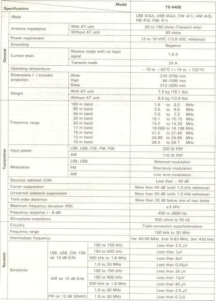
32 9-1. SPECIFICATIONS 9. 41
 cable cable.")

33 9-2. ACCESSORIES Dynamic microphone (Except Europe and U.K power assembly DC Calibration Fuse Knob (20A) cable cable. DIN Instruction Warranty plug (7-pin) card manual T E E , F K E B pc. 1 pc. 1 pc. 1 pc. 1 pc. 1 pc. 1 copy 1 copy 42
34 10. REFERENCE Antenna installation Fixed station For HF fixed-station operation, an antenna specifically designed for amateur operation is recommended. Antenna types include wire antennas, verticals, rotary beams, and other antenna types. (Fig. 10-1) HF antennas are quite large and must be installed strong wind, heavy rain, etc. to withstand Any antenna used with the TS-440S should be of 50-ohm impedance and should be connected using an appropriate coaxial cable such as RG-8/U. Impedance matching is important. Impedance mismatching will result in a high VSWR and power loss, or can cause unwanted harmonic radiation and interference (TVI, BCI). The impedance match can be checked with an SWR meter. Generally, satisfactory operation is assured when the VSWR (Voltage Standing Wave Ratio) is less than 1.5: 1. A rotary beam antenna is very effective for OX communication in the 14,21 and 28 MHz bands. (Fig. 10-2) If open wire or balanced type transmission line is used with the antenna, a suitable antenna tuner with balun is recommended between the transceiver and the feed line. Methods of construction and operating such tuners are described in detail in the ARRL Antenna Handbook, or similar publications. For operation on the 160,75 and 40 meter bands, a simple dipole antenna, cut to resonance in the most used portion of the band, will perform satisfactorily. For operation on the 10,15 and 20 meter bands, the efficiency of the station will be greatly increased if a good directional rotary antenna is used. Remember that even the most sophisticated transceiver is useless without a good antenna Mobile (1) Antenna Use a sturdy mount for the mobile antenna since HF antennas are larger (and have more wind load) and are heavier than VHF antennas. A bumper mount is recommended for general use. The ground side of the mount must be well grounded to the car body, since the body itself functions as the ground plane for the mobile antenna. (Refer to Fig. 10-4) Notes: 1. Some cars have plastic bumpers. For such cars, ground the antenna mount to the body. 2. When tuning a newly installed antenna, use the following procedure:.turn the CAR control fully counter-clockwise for minimum transmit power..with the transceiver in transmit mode. raise transmit power output slowly by rotaing the CAR control clockwise. The antenna should be adjusted with minimum power..transmitting with full power is recommended only after the antenna has been adjusted for a VSWR below 1.5:1. 3. Antenna installation is critical for successful mobile operation. For further information refer to THE RADIO AMATEUR'S HANDBOOK, RADIO HAND- BOOK, or other texts. Ground plane antenna (2) Coaxial cable connection When the antenna is mounted on the behicles bumper, the coaxial cable from the antenna can be routed through a drain hole in the trunk. When the antenna is roof mounted pass the cable between the body and door. Leave a driploop at the lowest point in the cable before entry into the vechicle to prevent water from entering the car. Fig Dipole antenna (3) Adjustment Some mobile antennas are not designed at 50-ohm impredance. In this case, impedance matching between the antenna and the coaxial cable (500) is required. This can be achieved by using an antenna matching device or coupler. 43
 The VSWR should preferably be less than 1.5: 1 for stisfactory operation. For antenna adjustment refer to the antenna instruction manual.")
35 --J I,-- The antenna to be used should first be checked with a dip meter to insure that it is designed for your operating band, then the impedance matching should be checked with an SWR meter. (Fig. 10-3) The VSWR should preferably be less than 1.5: 1 for stisfactory operation. For antenna adjustment refer to the antenna instruction manual. (4) Antenna matching In general, mobile antennas have a lower impedance than the 50-ohm coaxial cable used to feed them, resulting in a mismatch between the antenna and the coax. Such trouble can be eliminated by using an antenna tuner between the transceiver and the coaxial cable. 0 Matching circuit examples 10-2.MOBll OPERATION Installation Route battery and ANTENNA leads away from all high voltage secondary circuits to prevent ignition noise in- terference. Loading coil, Antenna -, Antenna must.., contact. --- j To antenna terminal./ / DraCKet Co bracket '" grommet Example of (power cord) wiring 44 Antenna bracket must have good metal to metal contact -,/I Since an HF antenna is large and heavy, it must be installed to withstand high wind stress. Pass coaxial cable through the drain hole. Fig. 10-4
36 Noise reduction In motor vehicles, noise is generated by the ignition system. Other sources of noise include the wiper and heater motors. Although the transceiver is equipped with a noise blanker to minimize ignition noise, it is imperative that some preventiye measures be taken to reduce the noise to the lowest possible level. ( 1) Antenna location selection Since ignition noise is generated by the vehicles en gine, the antenna must be installed as far from the en gine as possible. (2) Bonding The component parts of motor vehicles, such as the engine, transmission, muffler system, accelerator, etc., are coupled to one another at DC and low frequencies, but are isolated at high frequencies. By connecting these parts using heavy, braided ground straps, ignition noise can be reduced. This connection is called "bonding". (3) Use ignition suppressor cable or suppressor spark plugs Noise can be reduced by using spark plugs with internal resistors, or resistive suppressor ignition cable Battery capacity The power system of a motor vehicle is comprised of a battery and an alternator (which generates power while the engine is running) to supply current to loads or to charge the battery. Since the transceiver draws high current during transmit, care should be exercised so the power system is not overloaded. When using the transciever, the following points should be observed from the viewpont of battery maintenance: 1. Turn the transceiver OFF when the lights, heater, wipers and other high-draw accessories are used. 2. Avoid transceiver operation when the engine is not running. 3. If necessary. use an ammeter and/or a voltmeter to check battery condition. 45

 2nd Zone: South and North America 3rd Zone: Asia and Oceania (Soviet Russia. Turkey and Mongolia excluded).in some countries.")
37 10-3. RADIO FREQUENCY AllOCATION MHz 1st 2nd 3rd Zone Zone Zone 30 m amateur band g: gf ':"':':':':' 25 m broadcast band m amateur band "..'..."' m "...1 broa d cast ban d 17.55C , ,000 17m amateur band - 15 m ,...,..' amateur band ;13m,.broadcast band : :,:.:.:.:..:.:.:.:.:.:.:.:.: m amateur band 11m broadcast 28, m amateur band I band 1st Zone: Europe and Africa (Soviet Russia. Turkey and Mongolia included) 2nd Zone: South and North America 3rd Zone: Asia and Oceania (Soviet Russia. Turkey and Mongolia excluded).in some countries. table ---Standard frequencies allocations 0 time frequency Tropicalbroadcastband 0 Otherstations do not accord with this General broadcast band -Amateur band Radio Frequency Allocation Frequency distribution in the broadcast and amateur bands Notes: 1. Radio stations WORLD The general coverage receiver covers from 100 khz to 30 MHz, to receive international broadcast and communication As shown services. in the frequency 2. allocation chart, above figure, broadcast and amateur radio station frequencies are allocated in specific bands expressed in megahertz (MHz) or wavelength in meters (m). Also in the above figure the frequencies of "other stations" are assigned for fixed station business use, marine mobile, aviation mobile, land mobile, radio beacon stations, etc. :::.:.:.:.) 46 throughout RADIO cations. Antennas the world are listed in the TV HANDBOOK designed for or similar ham band operation pubilwill generally provide satisfactory reception for SW stations near the ham bands. For antenna construction details, or similar see the ARRL ANTENNA publications. HANDBOOK,
Elmer Session Hand Out for 3/3/11 de W6WTI. Some Common Controls Found On Amateur Radio Transceivers. (From ARRL web site tutorial)
") Elmer Session Hand Out for 3/3/11 de W6WTI Some Common Controls Found On Amateur Radio Transceivers. (From ARRL web site tutorial) The placement of the controls may vary from manufacturer to manufacturer
Elmer Session Hand Out for 3/3/11 de W6WTI Some Common Controls Found On Amateur Radio Transceivers. (From ARRL web site tutorial) The placement of the controls may vary from manufacturer to manufacturer
CON NEX HP. OWNER'S MANUAL Full Channel AM/FM Amateur Mobile Transceiver TABLE OF CONTENTS TUNING THE ANTENNA FOR OPTIMUM S.W.R..
 TABLE OF CONTENTS PAGE SPECIFICATIONS... 2 INSTALLATION... 3 LOCATION... 3 CON NEX - 4300HP MOUNTING THE RADIO... 3 IGNITION NOISE INTERFERENCE... 4 ANTENNA... 4 TUNING THE ANTENNA FOR OPTIMUM S.W.R..
QUICK REFERENCE GUIDE
 QUICK REFERENCE GUIDE Installation 1. Install a ground system for DC noise suppression and RFI suppression 2. Install your DC power supply 3. Install lightning protection. This will help protect more than
SUBELEMENT T4. Amateur radio practices and station set up. 2 Exam Questions - 2 Groups
 SUBELEMENT T4 Amateur radio practices and station set up 2 Exam Questions - 2 Groups 1 T4A Station setup: connecting microphones; reducing unwanted emissions; power source; connecting a computer; RF grounding;
INSTALLATION AND CONNECTIONS
 INSTALLATION AND CONNECTIONS 3 Unpacking After unpacking, immediately report any damage to the delivering carrier or dealer. Keep the shipping cartons. For a description and a diagram of accessory equipment
The amazing evolution of the 706 series
 The amazing evolution of the 706 series The IC-706MKIIG carries on the 706 series tradition of base station performance and features in a mobile reg-sized package. Building on this legacy, frequency coverage
i78 INSTRUCTION MANUAL HF TRANSCEIVER
 INSTRUCTION MANUAL HF TRANSCEIVER i78 This device complies with Part 15 of the FCC rules. Operation is subject to the following two conditions: (1) This device may not cause harmful interference, and (2)
DX AM FM SSB CW PA Amateur Base Station Transceiver OWNER S MANUAL RX / TX 2 4 POWER NF CHANNEL MODE RF POWER OFF CAL OFF OFF CALIBRATE
 1 2 3 6 4050 ULA 6070 TI 80 90 100 9 DX 2517 2517 RX / TX 0 2 4 SWR WATTS SET 81012 22 1 010 3 2030 5 MOD 7 ON dbover 9 SIGNAL +20 +40+60 PA FM AM USB LSB CW POWER ON SWR NB / ANL R.BEEP +10KHz NF CHANNEL
GRAND STRAND AMATEUR RADIO CLUB
 The GRAND STRAND AMATEUR RADIO CLUB (GSARC) Myrtle Beach SC is offering used amateur related equipment for sale. Written bids may be submitted to the GSARC up to Friday, November 23 rd, 2018. Only currently
Icom IC-9100 HF/VHF/UHF transceiver
 263 Walsall Road, Great Wyrley, Walsall, WS6 6DL Established 1997. Open Monday - Friday 9am - 5pm and Saturday 9.30am - 4pm Tel: 01922 414 796 Fax: 01922 417829 Skype: radioworld_uk Icom IC-9100 HF/VHF/UHF
TS-590SG HF/ 50MHz All-Mode TRANSCEIVER_
 New Product Release Information Oct 2014 TS-590SG HF/ 50MHz All-Mode TRANSCEIVER_ Kenwood introduces Updated to new G version new HF/50MHz All-Mode Transceiver Four years ago we launched our best-selling
Operation Manual. SlJPER ST AR Channel Mobile 5-Mode Transceiver -----~- --:.. KTSS200NXX ,, I
 Operation Manual!.,, SlJPER ST AR 2000 200 Channel Mobile 5-Mode Transceiver -----~- --:.. KTSS200NXX General Description l Frequency/Channel Chart The Super Star -2000 is a combination transmitter-receiver
KENWOOD SKY COMMAND SYSTEM
 KENWOOD SKY COMMAND SYSTEM Operation Manual KENWOOD COMMINICATIONS CORPORATION KENWOOD COMMUNICATIONS CORPORATION This operation manual is used for the KENWOOD SKY COMMAND SYSTEM (hereinafter referred
Technician License Course Chapter 5. Lesson Plan Module 11 Transmitters, Receivers and Transceivers
 Technician License Course Chapter 5 Lesson Plan Module 11 Transmitters, Receivers and Transceivers Generalized Transceiver Categories Mobile Single Band Dual Band All Band Multimode Handheld (HT) VHF/UHF
LnR Precision, Inc. 107 East Central Avenue, Asheboro, NC
 LD5 CW/SSB QRP Transceiver Quick guide manual Description: At the development base of the digital signal processing unit, an algorithm is embedded for IQ processing of the channels with phase suppression
INSTALLATION AND CONNECTIONS Section 2
 STLLTION ND CONNECTIONS Section Unpacking - ntenna jumper cable connection - Selecting a location - Rack mounting handle attachment - Grounding -3 ntenna connection -3 CF (Compact Flash) memory card -3
INSTRUCTION MANUAL VHF/UHF ALL MODE TRANSCEIVER. i910h
 INSTRUCTION MANUAL VHF/UHF ALL MODE TRANSCEIVER i910h IMPORTANT EXPLICIT DEFINITIONS READ THIS INSTRUCTION MANUAL CAREFULLY before attempting to operate the transceiver. SAVE THIS INSTRUCTION MANUAL. This
DX 73V OWNER S MANUAL FULL FEATURED AM/FM MOBILE TRANSCEIVER. WARRANTY This radio is covered by a two year limited parts and labor warranty.
 WARRANTY This radio is covered by a two year limited parts and labor warranty. Limited means that we will repair problems caused by factory defects or normal use at no charge. Before returning a radio
FT-897 Alignment. Local Oscillator Adjustment. PLL Adjustment
 FT-897 Local Oscillator Adjustment Reference Frequency Adjustment a. Connect a frequency counter to TP1032. b. Adjust the trimmer capacitor (TC5001) for 67.875000MHz ±5Hz on the frequency counter. c. Connect
DX 33HML. Full Channel AM/FM Mobile Transceiver OWNER S MANUAL. Printed In Malaysia AT H PD000802
 DX 33HML Full Channel AM/FM Mobile Transceiver Printed In Malaysia AT3601014H PD000802 OWNER S MANUAL TABLE OF CONTENTS Page Specification.................................... 2 Installation Location.....................................
LD5 CW/SSB QRP Transceiver SDR /DSP
 LD5 CW/SSB QRP Transceiver SDR /DSP Quick guide manual Description: At the development base of the digital signal processing unit, an algorithm is embedded for IQ processing of the channels with phase
Transceiver selection and Specs.
 Transceiver selection and Specs. Transceivers 1956-2018 From TUBES to SDR Covers 20-10 meters in 100Khz segments, 10 available, crystal needed for each. Plug in crystal holder. 100 Watts output, final
INSTRUCTION MANUAL. HF/ 50 MHz ALL MODE TRANSCEIVER TS-590S
 INSTRUCTION MANUAL HF/ 50 MHz ALL MODE TRANSCEIVER TS-590S NOTIFICATION This equipment complies with the essential requirements of Directive 1999/5/EC. The use of the warning symbol means the equipment
TS-590S INSTRUCTION MANUAL. HF/ 50 MHz ALL MODE TRANSCEIVER
 INSTRUCTION MANUAL HF/ 50 MHz ALL MODE TRANSCEIVER TS-590S NOTIFICATION This equipment complies with the essential requirements of Directive 1999/5/EC. The use of the warning symbol means the equipment
DX 33HP. 10 Meter Amateur Mobile Transceiver OWNER S MANUAL. Download this Manual Free of Charge at
 DX 33HP SIG 1 3 TX PWR 5 7 9+30dB POWER HI NB/ANL MED LO HI LO BAND ECHO RX/TX VOL SQ MIC RF FM PA AM D/A E/B F/C ECHO TIME BAND 10 Meter Amateur Mobile Transceiver Download this Manual Free of Charge
SPECS FEATURES SUPPLIED ACCESSORIES. HF All Band Transceiver
 718 HF All Band Transceiver RX 0.030-29.999999MHz* TX 1.800-1.999999 MHz** 3.500-3.999999 MHz** 7.000-7.300000 MHz 10.100-10.150000 MHz 14.000-14.350000 MHz 18.068-18.168000 MHz 21.000-21.450000 MHz 24.890-24.990000
The 21st Century R-390A/URR Reference Y2K-R3 Edited 7/09: No Technical Changes Chapter 2 - Operation. Page Table Of Contents 2-1
 Edited 7/09: No Technical Changes Chapter 2 - Operation Page Table Of Contents 2-1 2.1 Introduction. 2-2 2.2 Controls and Indicators 2-2 2.3 Operating Instructions And Control Settings 2-9 2.3.1 Pre-operational
DELUXE 18CHANNEL SSB/AM CB TRANSCEIVER OWNER'S GUIDE
 DELUXE 18CHANNEL SSB/AM CB TRANSCEIVER OWNER'S GUIDE General Description The Bush Ranger is a combination transmitter and receiver designed for use in the Australian 27 MHz Citizens radio service. It is
18-CHANNEL MOBILE CB TRANSCEIVER MODEL CB-845
 18-CHANNEL MOBILE CB TRANSCEIVER MODEL CB-845 INSTRUCTION HANDBOOK RAll JEFFERSOn CITIZEN BAND RADIO MESSAGE TO THE OWNER CONGRATULATIONS! As the new owner of Ray Jefferson Model CB-845 CB Mobile Transceiver,
OWNER'S MANUAL Channels All-Mode AM/FM/USB/LSB Built in Frequency Counter Mobile Transceiver with Roger Beep
 SUPER STAR 7QOODX OWNER'S MANUAL 3360 Channels All-Mode AM/FM/USB/LSB Built in Frequency Counter Mobile Transceiver with Roger Beep TABLE OF CONTENTS Page Specifications... 2 Installation Location... 4
ADJUSTING YOUR HF RECEIVER
 ADJUSTING YOUR HF RECEIVER N5KIP January 31, 2017 Disclaimers What works on one model of radio might not work well on another CW (narrow bandwidth) and SSB (wider bandwidth) will require different receiver
SUPERSTAR TABLE OF CONTENTS AM/FM/USB/LSB/CW AMATEUR MOBILE TRANSCEIVER WITH BUILT-IN FREQUENCY COUNTER OWNER S MANUAL
 SUPERSTAR TABLE OF CONTENTS AM/FM/USB/LSB/CW AMATEUR MOBILE TRANSCEIVER WITH BUILT-IN FREQUENCY COUNTER PAGE CHAPTER 1 Specifications............................................... 2 CHAPTER 2 Installation.................................................
KWM-2/2A Transceiver THE COLLINS KWM-2/2A TRANSCEIVER
 KWM-2/2A Transceiver Click the photo to see a larger photo Click "Back" button on browser to return Courtesy of Norm - WA3KEY THE COLLINS KWM-2/2A TRANSCEIVER Unmatched for versatility, dependability and
Installation... 3 Installing The Radio... 3 Ignition Noise Interference... 4 Antenna... 4 External Speaker... 4 Public Address...
 TABLE OF CONTENTS CHAPTER 1 Specifications.............................................. 2 PAGE BIG RIG SERIES S 1 MOD PW R 20 0 3 SW R 40 1 5 5 60 1.5 7 10 2 9 20 80 3 30 +20 40 50 +40 100% MAX db +60
CONTENTS SPECIFICATIONS...
 You are the owner of our latest product the new TS-780 Duo Band Transceiver. This unit has been carefully engineered and manufactured to rigid quality Standards, and should give you satisfactory and dependable
hallicrafters PERFORMANCE SPECIFICATIONS MODEL: SR-2000 LATEST REVISION: 18 JAN 66 Code ident # Specification #
 hallicrafters PERFORMANCE SPECIFICATIONS MODEL: SR-2000 LATEST REVISION: 18 JAN 66 Code ident # 26916 Specification # 093-002154 I. GENERAL A. Power input 117V 50-60 cycles from a source capable of delivering
INSTRUCTION MANUAL ALL MODE MULTI-BAND TRANSCEIVER TS-2000 TS-2000X TS-B2000
 B6--50 (K, E) 09 08 07 06 05 ALL MODE MULTI-BAND TRANSCEIVER TS-000 TS-000X TS-B000 INSTRUCTION MANUAL NOTIFICATION This equipment complies with the essential requirements of Directive 999/5/EC. The use
Operating Station Equipment
 Amateur Radio License Class Operating Station Equipment Presented by Steve Gallafent October 3, 2007 Operating Station Equipment Modulation Modulation is the process of adding information to a radio signal
Application for FCC / IC FCC ID: K X50 IC: 511B HF/50 MHz Transceiver FT-410 Operation Manual YAESU MUSEN CO., LTD. Tennozu Parkside Build
 HF/50 MHz Transceiver FT-410 Operation Manual YAESU MUSEN CO., LTD. Tennozu Parkside Building 2-5-8 Higashi-Shinagawa, Shinagawa-ku, Tokyo 140-0002 Japan YAESU USA 6125 Phyllis Drive, Cypress, CA 90630,
DX 99V OWNER S MANUAL. Full Channel AM/FM/SSB Mobile Built in Frequency Counter with Roger Beep
 WARRANTY This radio is covered by a two year limited parts and labor warranty. Limited means that we will repair problems caused by factory defects or normal use at no charge. Before returning a radio
Downloaded from
 TABLE OF CONTENTS Installation... 2 Location... 2 Mounting the Connection... 2 Ignition Noise Interference... 2 Antenna... 2 Tuning the Antenna for Optimum SWR... 3 External Speaker... 4 Replacing fuse...
INSTRUCTION MANUAL HF ALL BAND TRANSCEIVER. i718
 INSTRUCTION MANUAL HF ALL BAND TRANSCEIVER i718 IMPORTANT EXPLICIT DEFINITIONS READ ALL INSTRUCTIONS carefully and completely before using the transceiver. SAVE THIS INSTRUCTION MANUAL This instruction
Cat. No OWNER S MANUAL. HTX-212 Two-Meter Mobile Transceiver. Please read before using this transceiver.
 19-1125.fm Page 1 Tuesday, August 3, 1999 9:47 AM Cat. No. 19-1125 OWNER S MANUAL HTX-212 Two-Meter Mobile Transceiver Please read before using this transceiver. 19-1125.fm Page 2 Tuesday, August 3, 1999
RCI-6300F25/150. Owner's Manual. AM/FM Amateur Transceiver With Built-in Frequency Counter. Table of Contents. Downloaded from
 Table of Contents RCI-6300F25/150 AM/FM Amateur Transceiver With Built-in Frequency Counter PAGE Chapter 1 Specifications...... 2 Chapter 2 Installation...... 3 Installing the Radio... 3 Ignition Noise
INSTRUCTION MANUAL. HF/50 MHz TRANSCEIVER. i7200
 INSTRUCTION MANUAL HF/ MHz TRANSCEIVER i IMPORTANT R E A D T H I S I N S T RU C T I O N M A N UA L CAREFULLY before attempting to operate the transceiver SAVE THIS INSTRUCTION MANUAL This manual contains
Midland 248XL I NSTRUCTION GUI DE
 Midland 248XL I NSTRUCTION GUI DE INDEX Introduction...2 Function and location of the controls...3 Installation...7 Power supply...7 Installing an antenna...7 How to use your Midland 248XL...8 Frequency
DX 29HP. 10 Meter Amateur Mobile Transceiver OWNER S MANUAL PRINTED IN MALAYSIA PN:A412308CNA
 DX 29HP 10 Meter Amateur Mobile Transceiver OWNER S MANUAL PRINTED IN MALAYSIA PN:A412308CNA TABLE OF CONTENTS Page Specification.................................... 2 Installation Location.....................................
Chapter 15: Serial Controlled (HF) Radio Support
 Radio Support") 15-1 Chapter 15: Serial Controlled (HF) Radio Support This section describes the controller's interface for serial controlled radios. Most such radios are for the HF bands, but some such as the FT-736
15-1 Chapter 15: Serial Controlled (HF) Radio Support This section describes the controller's interface for serial controlled radios. Most such radios are for the HF bands, but some such as the FT-736
MIRAGE BD-35 DUAL BAND POWER AMPLIFIER
 MIRAGE BD-35 DUAL BAND POWER AMPLIFIER INTRODUCTION: The Mirage BD-35 is a 45/35 watt dual band power amplifier for use with today's dual band handie talkies operating in the 144/440MHz bands. We have
TOA NEW 900 SERIES MIXER PREAMPLIFIER M-900A
 Operation Instruction Manual TOA NEW 900 SERIES MIXER PREAMPLIFIER M-900A Features General Description 1 6-channel mixer preamplifier 2 Wide frequency response; 20 20,000Hz, ±1dB 3 Low distortion and noise
AM/FM/SSB/CW 12 & 10 METER MOBILE AMATEUR TRANSCEIVER OWNER S MANUAL
 AM/FM/SSB/CW 12 & 10 METER MOBILE AMATEUR TRANSCEIVER OWNER S MANUAL TABLE OF CONTENTS Warranty...2 Introduction...3 Installation... 4-5 Front Panel Controls... 6-8 Microphone...8 Menu Settings... 9-11
I.D.A. Operation manual
 TRX-200 Wide ide Band Receiver Operation manual Thank you for purchasing the TRX-200 all modes wide band monitoring receiver. Please read this operating manual carefully to avoid miss operation of the
ir2 INSTRUCTION MANUAL COMMUNICATIONS RECEIVER
 INSTRUCTION MANUAL COMMUNICATIONS RECEIVER ir2 This device complies with Part 15 of the FCC rules. Operation is subject to the following two conditions: (1) This device may not cause harmful interference,
DX 66V OWNER S MANUAL. Full Channel AM/FM Mobile Transceiver Built in Frequency Counter with Roger Beep
 WARRANTY This radio is covered by a two year limited parts and labor warranty. Limited means that we will repair problems caused by factory defects or normal use at no charge. Before returning a radio
IC-F7000. Advanced selective call and ALE make HF communication easier than ever!
 Page 1 of 5 HF TRANSCEIVER IC-F7000 Advanced selective call and ALE make HF communication easier than ever! The IC-F7000 is an HF land mobile transceiver especially designed forlong distance communications.
User Manual. Specifications...3. Control and Operation Microphone...8. Installation...9. Installation of Main Unit...9
 Contents Specifications...3 Control and Operation...4-7 Microphone...8 Installation...9 Installation of Main Unit...9 Antenna Installation...9 Operational test...9 Frequency Bands Table...10 Frequency
INSTRUCTION MANUAL. COMMUNICATIONS RECEIVER ir10
 INSTRUCTION MANUAL COMMUNICATIONS RECEIVER ir10 This device complies with Part 15 of the FCC rules. Operation is subject to the following two conditions: (1) This device may not cause harmful interference,
HF Receivers, Part 3
 HF Receivers, Part 3 Introduction to frequency synthesis; ancillary receiver functions Adam Farson VA7OJ View an excellent tutorial on receivers Another link to receiver principles NSARC HF Operators HF
TK-D740 TK-D740H TK-D740HV TK-D840 TK-D840H TK-D840HU
 TK-D740 TK-D740H TK-D740HV TK-D840 TK-D840H TK-D840HU VHF DIGITAL TRANSCEIVER UHF DIGITAL TRANSCEIVER USER MANUAL B5A 0925-00/01 Contents PREPARATION... 4 Connecting the power cable... 4 Installing the
Radio Receivers. Al Penney VO1NO
 Radio Receivers Al Penney VO1NO Role of the Receiver The Antenna must capture the radio wave. The desired frequency must be selected from all the EM waves captured by the antenna. The selected signal is
DX 93T OWNER S MANUAL. 10 Meter Amateur Mobile Transceiver With Built-in Frequency Counter & StarLite Face Plate TABLE OF CONTENTS CHAPTER 1 CHAPTER 2
 PAGE CHAPTER 1 Specifications.............................................. 2 Twin Turbine S 1 PW R 3 20 0 SW R 40 1 5 5 60 1.5 7 10 2 9 20 80 3 30 +20 40 50 DX 93T +40 100% MAX db +60 DX 93T B A SW R
Amateur Radio License. Radios, Power, RFI
 Amateur Radio License Radios, Power, RFI Todays Topics Types of Modulation : Chapter 2 Radio Equipment : Chapter 5 Radios Digital Communications Power Supplies and Batteries RF Interference, Grounding
WORLD BAND RADIO. AM/FM/SW/L W/AIR Band /SSB radio with LCD backlight OWNER S MANUAL
 WORLD BAND RADIO AM/FM/SW/L W/AIR Band /SSB radio with LCD backlight display and keypad direct entry OWNER S MANUAL WARNING Do not expose this appliance to rain or moisture Do not submerge or expose to
E L E C R A F T K 2 R E V I S I O N 2 F I R M W A R E
 E L E C R A F T K 2 R E V I S I O N 2 F I R M W A R E Installation and Reference Manual Rev. B, August 28, 2001 Summary of Changes... 2 Computer Control (KIO2)... 2 Transverter Bands... 2 RTTY/Data Mode
1. Your new Eagle 599 3
 Table of Contents 1. Your new Eagle 599 3 1.1. Unpacking Eagle 599 3 1.2. About this Manual 3 1.3. Accessory package 3 1.4. Connection to Antenna & Power Supply 4 1.5. A word about grounding 4 1.6. Philosophy
Radio Station Setup and Electrical Principles
 Radio Station Setup and Electrical Principles Covers sections: T4A-T5D Seth Price, N3MRA February 20, 2016 Outline 4.1 Station Setup 4.2 Operating Controls 4.3 Electronic Principles 4.4 Ohm s Law 4.5 Power
INSTRUCTION MANUAL VHF FM TRANSCEIVER TK-7102H UHF FM TRANSCEIVER TK-8102H KENWOOD CORPORATION B (M)
") INSTRUCTION MANUAL VHF FM TRANSCEIVER TK-7102H UHF FM TRANSCEIVER TK-8102H KENWOOD CORPORATION B62-1596-00 (M) 09 08 07 06 05 04 03 02 01 00 THANK YOU! We are grateful you chose KENWOOD for your personal
INSTRUCTION MANUAL VHF FM TRANSCEIVER TK-7102H UHF FM TRANSCEIVER TK-8102H KENWOOD CORPORATION B62-1596-00 (M) 09 08 07 06 05 04 03 02 01 00 THANK YOU! We are grateful you chose KENWOOD for your personal
ic-f1020 ic-f2020 INSTRUCTION MANUAL VHF LAND MOBILE RADIO UHF LAND MOBILE RADIO
 INSTRUCTION MANUAL VHF LAND MOBILE RADIO ic-f1020 UHF LAND MOBILE RADIO ic-f2020 This device complies with Part 15 of the FCC Rules. Operation is subject to the condition that this device does not cause
Frequency Coverage MHz RF Power Output 30W SSB / 9W AM/ 30W FM Dual Finals on Heat Sink Modes AM, FM, USB, LSB Microprocessor
 MAGNUM M-257 30W AM/ /FM/SSB 10--11 Meterr Mobile Trranscei ivverr n Prri iiccee: : US$ 250..00 eexx ssttoocckk JJaakkaarrttaa (Arrrri ( iivvi iinngg 2 d weeeekk iinn i Maarrcchh) ) SPECIFICATIONS Frequency
Lesson 9: Base Stations
 Lesson 9: Base Stations Preparation for Amateur Radio Technician Class Exam Topics Home Stations Basic Station Layout RTTY and Data Communications Station Accessories Wavelengths Feed Lines Impedance-matching
Zeon PDF Driver Trial
 401 W. 35th Street, Suite B National City, CA 91950 (800)446-5778. FAX( 619)426-3788 Email : rci@rangerusa.com http : //www.rangerusa.com Printed In Malaysia AT6960A11A PD000619 TR-936 SOLID STATE CITIZENS
MFJ-969 Versa Tuner II Instruction Manual
 MFJ-969 Versa Tuner II Instruction Manual General Information The MFJ-969 is a 300 watt RF output power antenna tuner that will match any transmitter or transceiver to virtually any antenna. Peak or average
Technician Licensing Class. Lesson 4. presented by the Arlington Radio Public Service Club Arlington County, Virginia
 Technician Licensing Class Lesson 4 presented by the Arlington Radio Public Service Club Arlington County, Virginia 1 Quiz Sub elements T6 & T7 2 Good Engineering Practice Sub element T8 3 A Basic Station
Introduction. CONT N NT S Cautions Before Operation 2. Major Features 3. Operating Controls and Functions 4. How to use Keyboard 6
 Introduction Congratulations! Now you are the owner of the most advanced state of the art VHF FM transceiver available today. Please read this manual carefully before attempting to operate your PCS 6000
INSTRUCTION MANUAL COMMUNICATIONS RECEIVER. ir75
 INSTRUCTION MANUAL COMMUNICATIONS RECEIVER ir75 IMPORTANT READ THIS INSTRUCTION MANUAL CAREFULLY before attempting to operate the receiver. SAVE THIS INSTRUCTION MANUAL. This manual contains important
HR MHZ AM-FM AMATEUR RADIO HF TRANSCEIVER OWNER'S MANUAL. Content of the packaging
 HR-2800 28 MHZ AM-FM AMATEUR RADIO HF TRANSCEIVER OWNER'S MANUAL NOTICE! It is recommended to carefully read this owner s manual before using the product. This will also help to prevent illegal use of
MFJ-752C SIGNAL ENHANCER II
 MFJ-752C SIGNAL ENHANCER II INTRODUCTION The improved MFJ-752C SIGNAL ENHANCER II is comprised of two tunable audio filtering systems designed to clarity and remove interfering signals from both voice
OM1006 Solid State 50 MHz Power Amplifier
 Instruction Manual OM1006 Solid State 50 MHz Power Amplifier OM POWER, s. r. o. 930 30 Báč 126 SLOVAKIA E-mail: om-power@om-power.com TABLE OF CONTENTS 1. GENERAL INFORMATION 1.1. Introduction.. 4 1.2.
AE 497 W (25-30 W-Version)
") User Manual AE 497 W (25-30 W-Version) 10-Meter Amateur Radio Base Station Legal notes and general information This amateur radio base station complies to the minimum requirements of the EU directives
User Manual AE 497 W (25-30 W-Version) 10-Meter Amateur Radio Base Station Legal notes and general information This amateur radio base station complies to the minimum requirements of the EU directives
INSTRUCTION MANUAL VHF FM TRANSCEIVER TK-6110 B (K,K2)
") INSTRUCTION MANUAL VHF FM TRANSCEIVER TK-6110 B62-1216-20 (K,K2) 09 08 07 06 05 04 03 02 THANK YOU! We are grateful you chose KENWOOD for your land mobile applications. We believe this easy-to-use transceiver
INSTRUCTION MANUAL VHF FM TRANSCEIVER TK-6110 B62-1216-20 (K,K2) 09 08 07 06 05 04 03 02 THANK YOU! We are grateful you chose KENWOOD for your land mobile applications. We believe this easy-to-use transceiver
Downloaded from
 Owner s Manual AM/FM 40 CHANNEL & TONE SQUELCH CITIZENS BAND TRANSCEIVER Downloaded from www.cbradio.nl Characteristics of C-Five 1. Improved audio sensitivity by adopting audio compressing and decompressing
ELECRAFT KX3 EXTENDED VFO TEMPERATURE COMPENSATION PROCEDURE Copyright 2012 Elecraft LLC Rev. A9, November 14, 2012
 ELECRAFT KX3 EXTENDED VFO TEMPERATURE COMPENSATION PROCEDURE Copyright 2012 Elecraft LLC Rev. A9, November 14, 2012 Introduction The KX3 standard VFO temperature compensation is entirely adequate for most
Zeon PDF Driver Trial
 401 W. 35th Street, Suite B National City, CA 91950 (800)446-5778. FAX( 619)426-3788 Email : rci@rangerusa.com http : //www.rangerusa.com Printed In Malaysia AT6960A11B PD000619 TR-966 SOLID STATE CITIZENS
TABLE OF CONTENTS 8 SOFTWARE MENU MODE SETTINGS SOFTWARE MENU QUICK GUIDE SERVICE MODE... 24
 1 TABLE OF CONTENTS 1. TABLE OF CONTENTS......................... 2 2. INTRODUCTION............................. 3 3. SPECIFICATIONS............................ 4 4. ACCESSORY PACKAGE.......................
AM/FM 10 METER MOBILE AMATEUR TRANSCEIVER OPERATING MANUAL
 AM/FM 10 METER MOBILE AMATEUR TRANSCEIVER OPERATING MANUAL INTRODUCTION Congratulations on your purchase of a Magnum S-6 AM/FM 10 meter transceiver. Your Magnum S-6 is designed to provide years of enjoyment
MFJ-949E. tuner antenowy skrzynka antenowa. Instrukcja obsługi. importer:
 Instrukcja obsługi MFJ-949E tuner antenowy skrzynka antenowa importer: PRO-FIT Centrum Radiokomunikacji InRadio ul. Puszkina 80 92-516 Łódź tel: 42 649 28 28 e-mail: biuro@inradio.pl www.inradio.pl MFJ-949E
AR-147 AR-247 AR-447 TMA-281A COMMANDO 246 BM
 AR-147 AR-247 AR-447 TMA-281A COMMANDO 246 BM MOBILE TRANSCEIVER USER'S MANUAL Thank you for purchasing this VHF/UHF mobile transceiver. IMPORTANT Please read this instruction manual carefully before attempting
Amateur Radio Examination EXAMINATION PAPER No. 275 MARKER S COPY
 01-6-(d) An Amateur Station is quoted in the regulations as a station: a for training new radio operators b using amateur equipment for commercial purposes c for public emergency purposes d in the Amateur
Radio Receivers. Al Penney VO1NO
 Radio Receivers Role of the Receiver The Antenna must capture the radio wave. The desired frequency must be selected from all the EM waves captured by the antenna. The selected signal is usually very weak
TS-590S ADJUSTMENT. Updating the Firmware. Required Test Equipment. Preparation
 Updating the Firmware The firmware of the main MCU and DSP can be updated using the TS590 Update update software. Update the firmware according to the procedure displayed in update software. Refer to the
WARNING: DO NOT PROCEED WITHOUT READING THIS PAGE.
 WARNING: DO NOT PROCEED WITHOUT READING THIS PAGE. The B-1030-G produces at least 300 watts of VHF R.F. power and is not to be taken lightly. Severe R.W. burns can be sustained at this power level! Power
MFJ-784B Instruction Manual. Contents. Fast Start...1 Before Reading This Manual...iv
 Contents Fast Start...1 Before Reading This Manual...iv Chapter 1 Introduction...1-1 Introduction to DSP...1-2 Product Overview...1-3 Block Diagram...1-4 Front Panel Layout...1-5 Back Panel Layout...1-6
INSTRUCTION MANUAL. HF/50 MHz TRANSCEIVER. i7410
 INSTRUCTION MANUAL HF/0 MHz TRANSCEIVER i0 i FOREWORD Thank you for making the IC-0 your radio of choice. We hope you agree with Icom s philosophy of technology first. Many hours of research and development
Rotary tuning knob /Fine tuning Clarify. Music/Normal /News Tone control SSB fine tune. Telescopic Antenna Earphones socket
 Control Locations Power/Sleep Power On/off/Alarm off/sleep function Display Switch between radio frequency and time while radio is power on Mode Mode set up (please see below mode button set up) Radio
TR 7800 TRIO KENWOOD VHF TRANSCEIVER
 TR 7800 TRIO KENWOOD VHF TRANSCEIVER SECTION 1 INSTALLATION 1-1 INTERCONNECTION Connect the antenna and power supply as shown in Fig. 1-1 for fixed station. 1-2 FIXED STATION Installation, [general] Power
INTRODUCTION OPERATING INSTRUCTIONS
 INTRODUCTION Welcome to the world of effortless CW, with the MFJ-403 you ll have a professional sounding fist in no time! Whether you re a Novice or seasoned Extra, the MFJ-403 has the features you ve
MIRAGE BD-38-G DUAL BAND POWER AMPLIFIER
 MIRAGE BD-38-G DUAL BAND POWER AMPLIFIER MIRAGE BD-38-G Dual Band Amplifier INTRODUCTION: The Mirage BD-38-G is a 80/60 watt dual band power amplifier for use with today's dual band handie talkies operating
ICOM INSTRUCTION MANUAL. Icom Inc. HF ALL BAND TRANSCEIVER GENERAL COVERAGE RECEIVER I C 735 NEIN. . ma FeTRANSCE!EP IC-715.
 Icom Inc. 0 ICOM INSTRUCTION MANUAL HF ALL BAND TRANSCEIVER GENERAL COVERAGE RECEIVER I C 735 PliONES MIC FeTRANSCE!EP IC-715 NEIN,-77111. ma. 7.1111 AM,MO WWI, SCAN, DOWN NI-C1.1 UP FOREWORD Thank you
PLL SYNTHESIZED RECEIVER FM STEREO / MW / LW / SW-SSB / AIR BAND OPERATION MANUAL TECSUN PL-660. Shortwave BW
 PL-660 PLL SYNTHESIZED RECEIVER FM STEREO / MW / LW / SW-SSB / AIR BAND OPERATION MANUAL TECSUN Shortwave BW FAST khz SYNC USB PL-660 AM SYNCHRONOUS DETECTOR FM STEREO/LW/MW/SW-SSB/AIR PLL SYNTHESIZED
WARNING: DO NOT PROCEED WITHOUT READING THIS PAGE.
 WARNING: DO NOT PROCEED WITHOUT READING THIS PAGE. The B-2530-G produces at least 300 watts of VHF R.F. power and is not to be taken lightly. Severe R.W. burns can be sustained at this power level! Power