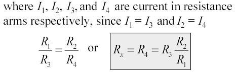
EE ELECTRICAL ENGINEERING AND INSTRUMENTATION
|
|
|
- Norma Cummings
- 5 years ago
- Views:
Transcription
1 EE ELECTRICAL ENGINEERING AND INSTRUMENTATION UNIT V ANALOG AND DIGITAL INSTRUMENTS Digital Voltmeter (DVM) It is a device used for measuring the magnitude of DC voltages. AC voltages can be measured after rectification and conversion to DC forms. DC/AC currents can be measured by passing them through a known resistance (internally or externally connected) and determining the voltage developed across the resistance (V=IxR). The result of the measurement is displayed on a digital readout in numeric form as in the case of the counters. Most DVMs use the principle of time period measurement. Hence, the voltage is converted into a time interval t first. No frequency division is involved. Input range selection automatically changes the position of the decimal point on the display. The unit of measure is also highlighted in most devices to simplify the reading and annotation. The block diagram shown below illustrates the principle of operation of a digital voltmeter. It is composed of an amplifier/attenuator, an analog to digital converter, storage, display and timing
2 circuits. There is also a power supply to provide the electrical power to run electronic components. The circuit components except the analog to digital converter circuits are similar to the ones used in electronic counters. The input range selection can be manually switched between ranges to get most accurate reading or it can be auto ranging that switches between ranges automatically for best reading. (i) Ramp type Digital Voltmeter Fig. 5.1 DVM Block Diagram Functional block diagram of a positive ramp type DVM is shown below. It has two major sections as the voltage to time conversion unit and time measurement unit. The conversion unit has a ramp generator that operates under the control of the sample rate oscillator, two comparators and a gate control circuitry. The internally generated ramp voltage is applied to two comparators. The first comparator compares the ramp voltage into the input signal and produces a pulse output as the coincidence is achieved (as the ramp voltage becomes larger than the input voltage). The second comparator compares the ramp to the ground voltage (0 volt) and produces an output pulse at the coincidence. The input voltage to the first comparator must be between Vm. The ranging and attenuation section scales the DC input voltage so that it will be within the dynamic range. The decimal point in the output display automatically positioned by the ranging circuits. Fig. 5.2 Ramp type Digital Voltmeter
3 Block Diagram of Ramp Type (Single Slope) DVM (ii) Dual slope integrating type Digital Voltmeter The ramp type DVM (single slope) is very simple yet has several drawbacks. The major limitation is the sensitivity of the output to system components and clock. The dual slope techniques eliminate the sensitivities and hence the mostly implemented approach in DVMs. The operation of the integrator and its output waveform are shown below. Fig. 5.3 Integrator and output waveforms The integrator works in two phases as charging and discharging. In phase-1, the switch connects the input of the integrator to the unknown input voltage ( Vin) for a predetermined time T and the integrator capacitor C charges through the input resistor R. The block diagram of the dual-slope type DVM is below. The figure illustrates the effects of the input voltage on charging and discharging phases of the converter. The total conversion time is the sum of the charging and discharging times. Yet, only the discharging time is used for the measurement and it is independent of the system components R and C, and the clock frequency. Fig. 5.4 Dual-Slope Type DVM
4 Introduction It is a common & important laboratory instrument. It is used to measure AC/DC voltage, AC/DC current and resistance with digital display. It gives digital display, which is very accurate. It has an advantage of very high input resistance. It also provides over ranging indicator. How digital multimeter works? The block diagram of DMM is given below. The working of each block to measure different types of electrical quantities is as follows. How to measure resistance? Connect an unknown resistor across its input probes. Keep rotary switch in the position-1 (refer block diagram below). The proportional current flows through the resistor, from constant current source. According to Ohm s law voltage is produced across it. This voltage is directly proportional to its resistance. This voltage is buffered and fed to A-D converter, to get digital display in Ohms. Fig. 5.5 DMM Block diagram of DMM How to measure AC voltage? Connect an unknown AC voltage across the input probes. Keep rotary switch in position-2. The voltage is attenuated, if it is above the selected range and then rectified to convert it into proportional DC voltage. It is then fed to A-D converter to get the digital display in Volts.
5 How to measure AC current? Current is indirectly measured by converting it into proportional voltage. Connect an unknown AC current across input probes. Keep the switch in position-3. The current is converted into voltage proportionally with the help of I-V converter and then rectified. Now the voltage in terms of AC current is fed to A-D converter to get digital display in Amperes. How to measure DC current? The DC current is also measured indirectly. Connect an unknown DC current across input probes. Keep the switch in position-4. The current is converted into voltage proportionally with the help of I-V converter. Now the voltage in terms of DC current is fed to A-D converter to get the digital display in Amperes. How to measure DC voltage? Connect an unknown DC voltage across input probes. Keep the switch in position-5. The voltage is attenuated, if it is above the selected range and then directly fed to A-D converter to get the digital display in Volts. Oscilloscopes also come in analog and digital types. An analog oscilloscope works by directly applying a voltage being measured to an electron beam moving across the oscilloscope screen. The voltage deflects the beam up and down proportionally, tracing the waveform on the screen. This gives an immediate picture of the waveform as described in previous sections. In contrast, a digital oscilloscope samples the waveform and uses an analog-to-digital converter (or ADC) to convert the voltage being measured into digital information. It then uses this digital information to reconstruct the waveform on the screen For many applications either an analog or digital oscilloscope will do. However, each type does possess some unique characteristics making it more or less suitable for specific tasks. People often prefer analog oscilloscopes when it is important to display rapidly varying signals in "real time" (or as they occur). Digital oscilloscopes allow us to capture and view events that may happen only once. They can process the digital waveform data or send the data to a computer for processing. Also, they can store the digital waveform data for later viewing and printing. Necessity for DSO and its Advantages If an object passes in front of our eyes more than about 24 times a second over the same trajectory, we cannot follow the trace of the object and we will see the trajectory as a continuous line of action. Hence, the trajectory is stored in our physiological system. This principle is used in obtaining a stationary trace needed to study waveforms in conventional oscilloscopes. This is however, is not possible for slowly varying signals and transients that occur once and then disappear. Storage oscilloscopes have been developed for this purpose.
6 Digital storage oscilloscopes came to existence in 1971 and developed a lot since then. They provide a superior method of trace storage. The waveform to be stored is digitized, stored in a digital memory, and retrieved for displayed on the storage oscilloscope. The stored waveform is continuously displayed by repeatedly scanning the stored waveform. The digitized waveform can be further analyzed by either the oscilloscope or by loading the content of the memory into a computer. They can present waveforms before, during and after trigger. They provide markers, called the cursors, to help the user in measurements in annotation (detailing) of the measured values. Principles of Operation A simplified block diagram of a digital storage oscilloscope is shown below. The input circuitry of the DSO and probes used for the measurement are the same as the conventional oscilloscopes. The input is attenuated and amplified with the input amplifiers as in any oscilloscope. This is done to scale the input signal so that the dynamic range of the A/D converter can be utilized maximally. Many DSOs can also operate in a conventional mode, bypassing the digitizing and storing features. The output of the input amplifier drives the trigger circuit that provides signal to the control logic. It is also sampled under the control of the control logic. The sample and hold circuit takes the sample and stores it as a charge on a capacitor. Hence, the value of the signal is kept constant during the analog to digital conversion. The analog to digital converter (A/D) generates a binary code related to the magnitude of the sampled signal. The speed of the A/D converter is important and flash converters are mostly used. The binary code from the A/D converter is stored in the memory. The memory consists of a bank of random access memory (RAM) integrated circuits (ICs). Fig. 5.6 Digital Storage Oscilloscope
7 Block diagram of a digital storage oscilloscope The Time-Base Circuit The control logic generates a clock signal applied to the binary counter. The counter accumulates pulses and produces a binary output code that delivered to a digital to analog (D/A) converter to generate the ramp signal applied to the horizontal deflection amplifier. The horizontal deflection plates are supplied with this ramp signal to let the electron to travel across the screen horizontally at a constant speed. The speed of the transition of electron depends upon the slope of the ramp that is controlled by the clock rate. The capacity of the counter is taken to have the maximum number accumulated corresponding to the rightmost position on the screen. With the next clock pulse, the binary output of the counter drops to all zeros yielding the termination of the ramp. The Displayed Signal Meanwhile, the data currently in the store is read out sequentially and the samples pass to the second D/A converter. There they are reconstructed into a series of discrete voltage levels forming a stepwise approximation of the original waveform. This is fed to the vertical deflection plates via the vertical deflection amplifier. For a multi-trace oscilloscope, each channel has the same circuitry and outputs of the D/A converters are combined in the vertical deflection amplifier. The delay line used in conventional oscilloscopes for synchronization is not needed in digital storage oscilloscopes since this function can be easily handled by the control logic. The read out and display of samples constituting the stored waveform need not occur at the same sample rate that was used to acquire the waveform in the first place. It is sufficient to use a display sample rate adequate to ensure that each and every trace displayed is rewritten fifty or more times a second to prevent the flicker of the display. Eventually, the time interval of the signal on the display is not Td of the input signal. Assume that we have a sampling rate of 1000 samples per second and we use 1000 samples for the display. The time referred to the input signal is Td = 1 second and it takes 1 second for the DSO to store the information into the memory. Writing to the memory and reading from the memory are independent activities. Once the information is stored, it can be read at any rate.. Current Trends The DSOs can work at low sweep rates allowing utilization of cheaper CRTs with wider screen and deflection yoke (coils that provide magnetic field instead of electrical field produced by the deflection plates). In some current DSOs, even liquid crystal displays (LCDs) are used with television like scanning techniques. This allows the development of hand-held and battery operated instruments. Some of these techniques will be dealt with in the section for display technologies. Content Signal Analog Analog signal is a continuous signal which represents physical measurements. Digital Digital signals are discrete time signals generated by digital modulation.
8 Waves Denoted by sine waves Denoted by square waves Example Human voice in air, analog electronic devices. Computers, CDs, DVDs, and other digital electronic devices. Representation Uses continuous range of values to represent information Uses discrete or discontinuous values to represent information Flexibility Analog hardware is not flexible. Digital hardware is flexible in implementation. Uses Can be used in analog devices Best suited for Computing and digita only. Best suited for audio an electronics. video transmission. Applications Thermometer PCs, PDAs Bandwidth Analog signal processing can be done in real time and Consumes less bandwidth. There is no guarantee that digital signal processing can be done in rea time and consumes more bandwidth t carry out the same information Stored in the form of binary bit Memory Stored in the form of wave signal Power Analog instrument draws Digital instrument draws only large power negligible power Cost Low cost and portable Cost is high and not easily portable Impedance Low High order of 100 mega ohm Errors Analog instruments usually have a scale which is cramped at lower end and give considerable observational errors. Digital instruments are free from observational errors like parallax and approximation errors. It is suitable for moderate resistance values: 1 ohm to 10 M ohm. Balanced condition, no potential difference across the galvanometer (there is no current through the galvanometer). Fig. 5.7 Wheat Stone Bridge
9
10 It is suitable for moderate resistance values: 1 ohm to ohm. Fig. 5.8 Kelvin s Double Bridge
11 Definition Schering Bridge is a bridge circuit used for measuring an unknown electrical capacitance and its dissipation factor. The dissipation factor of a capacitor is the ratio of its resistance to its capacitive reactance. The Schering Bridge is basically a four arm alternating-current (AC) bridge circuit whose measurement depends on balancing the loads on its arms. Explanation Fig Schering Bridge In the Schering Bridge above, the resistance values of resistors R1 and R2 are known, while the resistance value of resistor R3 is unknown. The capacitance values of C1 and C2 are also known, while the capacitance of C3 is the value being measured. To measure R3 and C3, the values of C2 and R2 are fixed, while the values of R1 and C1 are adjusted until the current through the ammeter between points A and B becomes zero. This happens when the voltages at points A and B are equal, in which case the bridge is said to be 'balanced'.
12 When the bridge is balanced, Z1/C2 = R2/Z3, where Z1 is the impedance of R1 in parallel with C1 and Z3 is the impedance of R3 in series with C3. In an AC circuit that has a capacitor, the capacitor contributes a capacitive reactance to the impedance. Z1 = R1/[2πfC1((1/2πfC1) + R1)] = R1/(1 + 2πfC1R1) while Z3 =1/2πfC3 + R3. 2πfC2R1/ (1+2πfC1R1) = R2/(1/2πfC3 + R3); or 2πfC2 (1/2πfC3 + R3) = (R2/R1) (1+2πfC1R1); or C2/C3 + 2πfC2R3 = R2/R1 + 2πfC1R2. When the bridge is balanced, the negative and positive reactive components are equal and cancel out, so 2πfC2R3 = 2πfC1R2 or R3 = C1R2 / C2. Similarly, when the bridge is balanced, the purely resistive components are equal, so C2/C3 = R2/R1 or C3 = R1C2 / R2. Note that the balancing of a Schering Bridge is independent of frequency. Advantages: Balance equation is independent of frequency Used for measuring the insulating properties of electrical cables and equipments
ANALOG AND DIGITAL INSTRUMENTS
 ANALOG AND DIGITAL INSTRUMENTS Digital Voltmeter (DVM) Used to measure the ac and dc voltages and displays the result in digital form. Types: Ramp type DVM Integrating type DVM Potentiometric type DVM
4. Digital Measurement of Electrical Quantities
 4.1. Concept of Digital Systems Concept A digital system is a combination of devices designed for manipulating physical quantities or information represented in digital from, i.e. they can take only discrete
Table of Contents...2. About the Tutorial...6. Audience...6. Prerequisites...6. Copyright & Disclaimer EMI INTRODUCTION Voltmeter...
 1 Table of Contents Table of Contents...2 About the Tutorial...6 Audience...6 Prerequisites...6 Copyright & Disclaimer...6 1. EMI INTRODUCTION... 7 Voltmeter...7 Ammeter...8 Ohmmeter...8 Multimeter...9
MAHARASHTRA STATE BOARD OF TECHNICAL EDUCATION (Autonomous) (ISO/IEC Certified) SUMMER 14 EXAMINATION Model Answer
 (ISO/IEC Certified) SUMMER 14 EXAMINATION Model Answer") MAHARASHTRA STATE BOARD OF TECHNICAL EDUCATION (Autonomous) (ISO/IEC 27001 2005 Certified) SUMMER 14 EXAMINATION Model Answer Subject Code : 17317 Page No: 1 Important Instructions to examiners: 1) The
MAHARASHTRA STATE BOARD OF TECHNICAL EDUCATION (Autonomous) (ISO/IEC 27001 2005 Certified) SUMMER 14 EXAMINATION Model Answer Subject Code : 17317 Page No: 1 Important Instructions to examiners: 1) The
SHRI ANGALAMMAN COLLEGE OF ENGINEERING & TECHNOLOGY (An ISO 9001:2008 Certified Institution) SIRUGANOOR,TRICHY
 SIRUGANOOR,TRICHY") SHRI ANGALAMMAN COLLEGE OF ENGINEERING & TECHNOLOGY (An ISO 9001:2008 Certified Institution) SIRUGANOOR,TRICHY-621105. DEPARTMENT OF ELECTRICAL AND ELECTRONICS ENGINEERING EI 1306-MEASUREMENT AND INSTRUMENTATION
SHRI ANGALAMMAN COLLEGE OF ENGINEERING & TECHNOLOGY (An ISO 9001:2008 Certified Institution) SIRUGANOOR,TRICHY-621105. DEPARTMENT OF ELECTRICAL AND ELECTRONICS ENGINEERING EI 1306-MEASUREMENT AND INSTRUMENTATION
Number of Lessons:155 #14B (P) Electronics Technology with Digital and Microprocessor Laboratory Completion Time: 42 months
 Electronics Technology with Digital and Microprocessor Laboratory Completion Time: 42 months") PROGRESS RECORD Study your lessons in the order listed below. Number of Lessons:155 #14B (P) Electronics Technology with Digital and Microprocessor Laboratory Completion Time: 42 months 1 2330A Current
PROGRESS RECORD Study your lessons in the order listed below. Number of Lessons:155 #14B (P) Electronics Technology with Digital and Microprocessor Laboratory Completion Time: 42 months 1 2330A Current
CHAPTER 6 DIGITAL INSTRUMENTS
 CHAPTER 6 DIGITAL INSTRUMENTS 1 LECTURE CONTENTS 6.1 Logic Gates 6.2 Digital Instruments 6.3 Analog to Digital Converter 6.4 Electronic Counter 6.6 Digital Multimeters 2 6.1 Logic Gates 3 AND Gate The
Electronic Instrumentation & Automation. ET-7th semester. By : Rahul Sharma ET & TC Deptt. RCET, Bhilai
 Electronic Instrumentation & Automation ET-7th semester By : Rahul Sharma ET & TC Deptt. RCET, Bhilai UNIT: III Voltage and Current Measurements Digital Voltmeters: Non-Integrating type, Integrating Type,
Laboratory Exercise 6 THE OSCILLOSCOPE
 Introduction Laboratory Exercise 6 THE OSCILLOSCOPE The aim of this exercise is to introduce you to the oscilloscope (often just called a scope), the most versatile and ubiquitous laboratory measuring
Bhoj Reddy Engineering College for Women, Hyderabad Department of Electronics and Communication Engineering Electrical and Electronics Instrumentation
 Bhoj Reddy Engineering College for Women, Hyderabad Department of Electronics and Communication Engineering Electrical and Electronics Instrumentation Academic Year: 2016-17 III B Tech II Semester Branch:
Digital multimeter IENGINEERS- CONSULTANTS LECTURE NOTES SERIES ELECTRONICS ENGINEERING 1 YEAR UPTU. Page 1
 Digital multimeter Measurement of any quantity is a result of comparison between the quantity to be measured and a definite world wide standard. The instruments which are used for such comparison are called
MAHARASHTRA STATE BOARD OF TECHNICAL EDUCATION (Autonomous) (ISO/IEC Certified) SUMMER 2013 EXAMINATION
 (ISO/IEC Certified) SUMMER 2013 EXAMINATION") MAHARASHTRA STATE BOARD OF TECHNICAL EDUCATION (Autonomous) (ISO/IEC 27001 2005 Certified) SUMMER 2013 EXAMINATION Subject Code: 12117 Model Answer Page No: 1 Important Instructions to examiners: 1) The
MAHARASHTRA STATE BOARD OF TECHNICAL EDUCATION (Autonomous) (ISO/IEC 27001 2005 Certified) SUMMER 2013 EXAMINATION Subject Code: 12117 Model Answer Page No: 1 Important Instructions to examiners: 1) The
MAHARASHTRA STATE BOARD OF TECHNICAL EDUCATION (Autonomous) (ISO/IEC Certified)
 (ISO/IEC Certified)") Q. No. WINTER 16 EXAMINATION (Subject Code: 17317) Model Answer Important Instructions to examiners: 1) The answers should be examined by key words and not as word-to-word as given in the model answer
Q. No. WINTER 16 EXAMINATION (Subject Code: 17317) Model Answer Important Instructions to examiners: 1) The answers should be examined by key words and not as word-to-word as given in the model answer
Test No. 1. Introduction to Scope Measurements. Report History. University of Applied Sciences Hamburg. Last chance!! EEL2 No 1
 University of Applied Sciences Hamburg Group No : DEPARTMENT OF INFORMATION ENGINEERING Laboratory for Instrumentation and Measurement L: in charge of the report Test No. Date: Assistant A2: Professor:
Associate In Applied Science In Electronics Engineering Technology Expiration Date:
 PROGRESS RECORD Study your lessons in the order listed below. Associate In Applied Science In Electronics Engineering Technology Expiration Date: 1 2330A Current and Voltage 2 2330B Controlling Current
DEPARTMENT OF INFORMATION ENGINEERING. Test No. 1. Introduction to Scope Measurements. 1. Correction. Term Correction. Term...
 2. Correction. Correction Report University of Applied Sciences Hamburg Group No : DEPARTMENT OF INFORMATION ENGINEERING Laboratory for Instrumentation and Measurement L: in charge of the report Test No.
UNIT 2. Q.1) Describe the functioning of standard signal generator. Ans. Electronic Measurements & Instrumentation
 Describe the functioning of standard signal generator. Ans. Electronic Measurements & Instrumentation") UNIT 2 Q.1) Describe the functioning of standard signal generator Ans. STANDARD SIGNAL GENERATOR A standard signal generator produces known and controllable voltages. It is used as power source for the
UNIT 2 Q.1) Describe the functioning of standard signal generator Ans. STANDARD SIGNAL GENERATOR A standard signal generator produces known and controllable voltages. It is used as power source for the
Elizabethtown College Department of Physics and Engineering PHY104. Lab # 9- Oscilloscope and RC Circuit
 Elizabethtown College Department of Physics and Engineering PHY104 Lab # 9- Oscilloscope and RC Circuit Introduction This lab introduces you to very important tools, the oscilloscope and the waveform generator.
EEE312: Electrical measurement & instrumentation
 University of Turkish Aeronautical Association Faculty of Engineering EEE department EEE312: Electrical measurement & instrumentation Digital Electronic meters BY Ankara March 2017 1 Introduction The digital
Rayat Shikshan Sanstha s Karmaveer Bhaurao Patil Polytechnic, Satara. Sub: Electrical Engineering Assignment No: 1
 Assignment No: 1 1) Define Precision and Dead zone 2) Define 1) Speed of response 2) Lag 3) Fidelity 4)dynamic error 3) Define Standard and State its classification 4) What is Calibration & State its necessity
MAHARASHTRA STATE BOARD OF TECHNICAL EDUCATION (Autonomous) (ISO/IEC Certified) MODEL ANSWER
 (ISO/IEC Certified) MODEL ANSWER") MODEL ANSWER SUMMER 17 EXAMINATION Subject Title: Electronic Instruments and Measurements Subject Code: Important Instructions to examiners: 1) The answers should be examined by key words and not as word-to-word
MODEL ANSWER SUMMER 17 EXAMINATION Subject Title: Electronic Instruments and Measurements Subject Code: Important Instructions to examiners: 1) The answers should be examined by key words and not as word-to-word
Using Circuits, Signals and Instruments
 Using Circuits, Signals and Instruments To be ignorant of one s ignorance is the malady of the ignorant. A. B. Alcott (1799-1888) Some knowledge of electrical and electronic technology is essential for
Laboratory 3 (drawn from lab text by Alciatore)
") Laboratory 3 (drawn from lab text by Alciatore) The Oscilloscope Required Components: 1 10 resistor 2 100 resistors 2 lk resistors 1 2k resistor 2 4.7M resistors 1 0.F capacitor 1 0.1 F capacitor 1 1.0uF
Laboratory 3 (drawn from lab text by Alciatore) The Oscilloscope Required Components: 1 10 resistor 2 100 resistors 2 lk resistors 1 2k resistor 2 4.7M resistors 1 0.F capacitor 1 0.1 F capacitor 1 1.0uF
332:223 Principles of Electrical Engineering I Laboratory Experiment #2 Title: Function Generators and Oscilloscopes Suggested Equipment:
 RUTGERS UNIVERSITY The State University of New Jersey School of Engineering Department Of Electrical and Computer Engineering 332:223 Principles of Electrical Engineering I Laboratory Experiment #2 Title:
Lab E5: Filters and Complex Impedance
 E5.1 Lab E5: Filters and Complex Impedance Note: It is strongly recommended that you complete lab E4: Capacitors and the RC Circuit before performing this experiment. Introduction Ohm s law, a well known
Definitions. Spectrum Analyzer
 SIGNAL ANALYZERS Spectrum Analyzer Definitions A spectrum analyzer measures the magnitude of an input signal versus frequency within the full frequency range of the instrument. The primary use is to measure
PHY152 Experiment 4: Oscillations in the RC-Circuits (Measurements with an oscilloscope)
") PHY152 Experiment 4: Oscillations in the RC-Circuits (Measurements with an oscilloscope) If you have not used an oscilloscope before, the web site http://www.upscale.utoronto.ca/generalinterest/harrison/oscilloscope/oscilloscope.html
PHY152 Experiment 4: Oscillations in the RC-Circuits (Measurements with an oscilloscope) If you have not used an oscilloscope before, the web site http://www.upscale.utoronto.ca/generalinterest/harrison/oscilloscope/oscilloscope.html
Basic Analog Circuits
 Basic Analog Circuits Overview This tutorial is part of the National Instruments Measurement Fundamentals series. Each tutorial in this series, will teach you a specific topic of common measurement applications,
b) State the types of standards of measurement. 2M
 State the types of standards of measurement. 2M") MODEL ANSWER WINTER 17 EXAMINATION Subject Title: Electronic Instruments & Measurements Subject Code: 17317 I m p o r t a n t I n s t r u c t i o n s t o e x a m i n e r s : 1) The answers should be examined
MODEL ANSWER WINTER 17 EXAMINATION Subject Title: Electronic Instruments & Measurements Subject Code: 17317 I m p o r t a n t I n s t r u c t i o n s t o e x a m i n e r s : 1) The answers should be examined
electrical noise and interference, environmental changes, instrument resolution, or uncertainties in the measurement process itself.
 MUST 382 / EELE 491 Spring 2014 Basic Lab Equipment and Measurements Electrical laboratory work depends upon various devices to supply power to a circuit, to generate controlled input signals, and for
Basic Communication Laboratory Manual. Shimshon Levy&Harael Mualem
 Basic Communication Laboratory Manual Shimshon Levy&Harael Mualem September 2006 CONTENTS 1 The oscilloscope 2 1.1 Objectives... 2 1.2 Prelab... 2 1.3 Background Theory- Analog Oscilloscope...... 3 1.4
CHAPTER 6. Motor Driver
 CHAPTER 6 Motor Driver In this lab, we will construct the circuitry that your robot uses to drive its motors. However, before testing the motor circuit we will begin by making sure that you are able to
Name Date: Course number: MAKE SURE TA & TI STAMPS EVERY PAGE BEFORE YOU START EXPERIMENT 10. Electronic Circuits
 Laboratory Section: Last Revised on September 21, 2016 Partners Names: Grade: EXPERIMENT 10 Electronic Circuits 1. Pre-Laboratory Work [2 pts] 1. How are you going to determine the capacitance of the unknown
1 Second Time Base From Crystal Oscillator
 1 Second Time Base From Crystal Oscillator The schematic below illustrates dividing a crystal oscillator signal by the crystal frequency to obtain an accurate (0.01%) 1 second time base. Two cascaded 12
EE283 Electrical Measurement Laboratory Laboratory Exercise #7: Digital Counter
 EE283 Electrical Measurement Laboratory Laboratory Exercise #7: al Counter Objectives: 1. To familiarize students with sequential digital circuits. 2. To show how digital devices can be used for measurement
Data acquisition and instrumentation. Data acquisition
 Data acquisition and instrumentation START Lecture Sam Sadeghi Data acquisition 1 Humanistic Intelligence Body as a transducer,, data acquisition and signal processing machine Analysis of physiological
University of Jordan School of Engineering Electrical Engineering Department. EE 204 Electrical Engineering Lab
 University of Jordan School of Engineering Electrical Engineering Department EE 204 Electrical Engineering Lab EXPERIMENT 1 MEASUREMENT DEVICES Prepared by: Prof. Mohammed Hawa EXPERIMENT 1 MEASUREMENT
Test No. 2. Advanced Scope Measurements. History. University of Applied Sciences Hamburg. Last chance!! EEL2 No 2
 University of Applied Sciences Hamburg Group No : DEPARTMENT OF INFORMATION ENGINEERING Laboratory for Instrumentation and Measurement L1: in charge of the report Test No. 2 Date: Assistant A2: Professor:
Contents. Acknowledgments. About the Author
 Contents Figures Tables Preface xi vii xiii Acknowledgments About the Author xv xvii Chapter 1. Basic Mathematics 1 Addition 1 Subtraction 2 Multiplication 2 Division 3 Exponents 3 Equations 5 Subscripts
Data Converters. Dr.Trushit Upadhyaya EC Department, CSPIT, CHARUSAT
 Data Converters Dr.Trushit Upadhyaya EC Department, CSPIT, CHARUSAT Purpose To convert digital values to analog voltages V OUT Digital Value Reference Voltage Digital Value DAC Analog Voltage Analog Quantity:
10. Chapter: A/D and D/A converter principles
 Punčochář, Mohylová: TELO, Chapter 10: A/D and D/A converter principles 1 10. Chapter: A/D and D/A converter principles Time of study: 6 hours Goals: the student should be able to define basic principles
SUMMER 15 EXAMINATION
 SUMMER 15 EXAMINATION Subject Code: 17317 Model Answer Important Instructions to examiners: 1) The answers should be examined by key words and not as word-to-word as given in the model answer scheme. 2)
B. Equipment. Advanced Lab
 Advanced Lab Measuring Periodic Signals Using a Digital Oscilloscope A. Introduction and Background We will use a digital oscilloscope to characterize several different periodic voltage signals. We will
MEASUREMENTS & INSTRUMENTATION ANALOG AND DIGITAL METERS
 MEASUREMENTS & INSTRUMENTATION ANALOG AND DIGITAL METERS ANALOG Metering devices Provides monotonous (continuous) movement. ELECTRICAL MEASURING INSTRUMENTS ANALOG METERS A d Arsonval galvanometer (Moving
Electronic Measurements & Instrumentation UNIT What are the basic performance characteristics of a system?
 UNIT-1 1. What are the basic performance characteristics of a system? Ans: STATIC CHARACTE RISTICS The static characteristics of an instrument are, in general, considered for instruments which are used
ELECTRONICS ADVANCED SUPPLEMENTARY LEVEL
 ELECTRONICS ADVANCED SUPPLEMENTARY LEVEL AIMS The general aims of the subject are : 1. to foster an interest in and an enjoyment of electronics as a practical and intellectual discipline; 2. to develop
EXPERIMENT 1 PRELIMINARY MATERIAL
 EXPERIMENT 1 PRELIMINARY MATERIAL BREADBOARD A solderless breadboard, like the basic model in Figure 1, consists of a series of square holes, and those columns of holes are connected to each other via
ME 365 EXPERIMENT 1 FAMILIARIZATION WITH COMMONLY USED INSTRUMENTATION
 Objectives: ME 365 EXPERIMENT 1 FAMILIARIZATION WITH COMMONLY USED INSTRUMENTATION The primary goal of this laboratory is to study the operation and limitations of several commonly used pieces of instrumentation:
UNIT-3. Electronic Measurements & Instrumentation
 UNIT-3 1. Draw the Block Schematic of AF Wave analyzer and explain its principle and Working? ANS: The wave analyzer consists of a very narrow pass-band filter section which can Be tuned to a particular
Chapter 2 Signal Conditioning, Propagation, and Conversion
 09/0 PHY 4330 Instrumentation I Chapter Signal Conditioning, Propagation, and Conversion. Amplification (Review of Op-amps) Reference: D. A. Bell, Operational Amplifiers Applications, Troubleshooting,
ENGR 210 Lab 12: Analog to Digital Conversion
 ENGR 210 Lab 12: Analog to Digital Conversion In this lab you will investigate the operation and quantization effects of an A/D and D/A converter. A. BACKGROUND 1. LED Displays We have been using LEDs
Analog I/O. ECE 153B Sensor & Peripheral Interface Design Winter 2016
 Analog I/O ECE 153B Sensor & Peripheral Interface Design Introduction Anytime we need to monitor or control analog signals with a digital system, we require analogto-digital (ADC) and digital-to-analog
B.E. SEMESTER III (ELECTRICAL) SUBJECT CODE: X30902 Subject Name: Analog & Digital Electronics
 SUBJECT CODE: X30902 Subject Name: Analog & Digital Electronics") B.E. SEMESTER III (ELECTRICAL) SUBJECT CODE: X30902 Subject Name: Analog & Digital Electronics Sr. No. Date TITLE To From Marks Sign 1 To verify the application of op-amp as an Inverting Amplifier 2 To
B.E. SEMESTER III (ELECTRICAL) SUBJECT CODE: X30902 Subject Name: Analog & Digital Electronics Sr. No. Date TITLE To From Marks Sign 1 To verify the application of op-amp as an Inverting Amplifier 2 To
ET1210: Module 5 Inductance and Resonance
 Part 1 Inductors Theory: When current flows through a coil of wire, a magnetic field is created around the wire. This electromagnetic field accompanies any moving electric charge and is proportional to
AME140 Lab #2 INTRODUCTION TO ELECTRONIC TEST EQUIPMENT AND BASIC ELECTRONICS MEASUREMENTS
 INTRODUCTION TO ELECTRONIC TEST EQUIPMENT AND BASIC ELECTRONICS MEASUREMENTS The purpose of this document is to guide students through a few simple activities to increase familiarity with basic electronics
Lecture 3: Sensors, signals, ADC and DAC
 Instrumentation and data acquisition Spring 2010 Lecture 3: Sensors, signals, ADC and DAC Zheng-Hua Tan Multimedia Information and Signal Processing Department of Electronic Systems Aalborg University,
Q.1 a) Attempt any SIX of the following: 12M. (i) Give comparison between active transducer and passive transducer. Ans:- (Any Two) 1M each
 Attempt any SIX of the following: 12M. (i) Give comparison between active transducer and passive transducer. Ans:- (Any Two) 1M each") Page 1 of 26 Important Instructions to examiners: 1) The answers should be examined by key words and not as word-to-word as given in the Model answer scheme. 2) The model answer and the answer written
Page 1 of 26 Important Instructions to examiners: 1) The answers should be examined by key words and not as word-to-word as given in the Model answer scheme. 2) The model answer and the answer written
11. AC-resistances of capacitor and inductors: Reactances.
 11. AC-resistances of capacitor and inductors: Reactances. Purpose: To study the behavior of the AC voltage signals across elements in a simple series connection of a resistor with an inductor and with
Dedan Kimathi University of technology. Department of Electrical and Electronic Engineering. EEE2406: Instrumentation. Lab 2
 Dedan Kimathi University of technology Department of Electrical and Electronic Engineering EEE2406: Instrumentation Lab 2 Title: Analogue to Digital Conversion October 2, 2015 1 Analogue to Digital Conversion
Lab 2 Revisited Exercise
 Lab 2 Revisited Exercise +15V 100k 1K 2N2222 Wire up led display Note the ground leads LED orientation 6.091 IAP 2008 Lecture 3 1 Comparator, Oscillator +5 +15 1k 2 V- 7 6 Vin 3 V+ 4 V o Notice that power
Navy Electricity and Electronics Training Series
 NONRESIDENT TRAINING COURSE SEPTEMBER 1998 Navy Electricity and Electronics Training Series Module 9 Introduction to Wave- Generation and Wave-Shaping NAVEDTRA 14181 DISTRIBUTION STATEMENT A: Approved
DLVP A OPERATOR S MANUAL
 DLVP-50-300-3000A OPERATOR S MANUAL DYNALOAD DIVISION 36 NEWBURGH RD. HACKETTSTOWN, NJ 07840 PHONE (908) 850-5088 FAX (908) 908-0679 TABLE OF CONTENTS INTRODUCTION...3 SPECIFICATIONS...5 MODE SELECTOR
Chapter 2 Analog-to-Digital Conversion...
 Chapter... 5 This chapter examines general considerations for analog-to-digital converter (ADC) measurements. Discussed are the four basic ADC types, providing a general description of each while comparing
EE 241 Experiment #7: NETWORK THEOREMS, LINEARITY, AND THE RESPONSE OF 1 ST ORDER RC CIRCUITS 1
 EE 241 Experiment #7: NETWORK THEOREMS, LINEARITY, AND THE RESPONSE OF 1 ST ORDER RC CIRCUITS 1 PURPOSE: To verify the validity of Thevenin and maximum power transfer theorems. To demonstrate the linear
EE 201 Function / Arbitrary Waveform Generator and Oscilloscope Tutorial
 EE 201 Function / Arbitrary Waveform Generator and Oscilloscope Tutorial 1 This is a programmed learning instruction manual. It is written for the Agilent DSO3202A Digital Storage Oscilloscope. The prerequisite
UNIT I LINEAR WAVESHAPING
 UNIT I LINEAR WAVESHAPING. High pass, low pass RC circuits, their response for sinusoidal, step, pulse, square and ramp inputs. RC network as differentiator and integrator, attenuators, its applications
DEPARTMENT OF ELECTRICAL ENGINEERING LAB WORK EE301 ELECTRONIC CIRCUITS
 DEPARTMENT OF ELECTRICAL ENGINEERING LAB WORK EE301 ELECTRONIC CIRCUITS EXPERIMENT : 1 TITLE : Half-Wave Rectifier & Filter OUTCOME : Upon completion of this unit, the student should be able to: i. Construct
DEPARTMENT OF ELECTRICAL ENGINEERING
 DEPARTMENT OF ELECTRICAL ENGINEERING LAB MANUAL SUBJECT: EMI B.TECH -3 RD SEM KCT COLLEGE OF ENGG & TECH FATEHGARH PUNJAB TECHNICAL UNIVERSITY Prepared by:- Er. Prince Munjal (AP) B.Tech (EE) M.Tech( EE)
Mechatronics. Analog and Digital Electronics: Studio Exercises 1 & 2
 Mechatronics Analog and Digital Electronics: Studio Exercises 1 & 2 There is an electronics revolution taking place in the industrialized world. Electronics pervades all activities. Perhaps the most important
FYSP1110/K1 (FYSP110/K1) USE OF AN OSCILLOSCOPE
 USE OF AN OSCILLOSCOPE") FYSP1110/K1 (FYSP110/K1) USE OF AN OSCILLOSCOPE 1 Introduction In this exercise you will get basic knowledge about how to use an oscilloscope. You ll also measure properties of components, which you are
FYSP1110/K1 (FYSP110/K1) USE OF AN OSCILLOSCOPE 1 Introduction In this exercise you will get basic knowledge about how to use an oscilloscope. You ll also measure properties of components, which you are
Combinational logic: Breadboard adders
 ! ENEE 245: Digital Circuits & Systems Lab Lab 1 Combinational logic: Breadboard adders ENEE 245: Digital Circuits and Systems Laboratory Lab 1 Objectives The objectives of this laboratory are the following:
Spectrum analyzer for frequency bands of 8-12, and MHz
 EE389 Electronic Design Lab Project Report, EE Dept, IIT Bombay, November 2006 Spectrum analyzer for frequency bands of 8-12, 12-16 and 16-20 MHz Group No. D-13 Paras Choudhary (03d07012)
Oscilloscope Measurements
 PC1143 Physics III Oscilloscope Measurements 1 Purpose Investigate the fundamental principles and practical operation of the oscilloscope using signals from a signal generator. Measure sine and other waveform
HIGH LOW Astable multivibrators HIGH LOW 1:1
 1. Multivibrators A multivibrator circuit oscillates between a HIGH state and a LOW state producing a continuous output. Astable multivibrators generally have an even 50% duty cycle, that is that 50% of
1. A) Attempt any six of the following: [12M]
![1. A) Attempt any six of the following: [12M]](/thumbs/95/125538661.jpg "1. A) Attempt any six of the following: [12M]") Subject Code: 17435 Model Answer Page 1 of 29 Important Instructions to examiners: 1) The answers should be examined by key words and not as word-to-word as given in the Model answer scheme. 2) The model
Subject Code: 17435 Model Answer Page 1 of 29 Important Instructions to examiners: 1) The answers should be examined by key words and not as word-to-word as given in the Model answer scheme. 2) The model
DE59 ELECTRONIC INSTRUMENTATION & MEASUREMENT 2012
 Q.2 a. Define the terms: Ans. (i) Accuracy: It is the closeness with which an instrument reading approaches the true value of the quantity being measured. Accuracy (in percent) =100 - %ε r (ii) (iii) (iv)
SYLLABUS MODULE 1: Measurement and Error: Definitions, Accuracy and Precision, Significant Figures, Types of Error, Statistical Analysis, Probability
 SYLLABUS MODULE 1: Measurement and Error: Definitions, Accuracy and Precision, Significant Figures, Types of Error, Statistical Analysis, Probability of Errors, Limiting Errors. Relevant problems. Ammeters:
For the filter shown (suitable for bandpass audio use) with bandwidth B and center frequency f, and gain A:
 with bandwidth B and center frequency f, and gain A:") Basic Op Amps The operational amplifier (Op Amp) is useful for a wide variety of applications. In the previous part of this article basic theory and a few elementary circuits were discussed. In order to
Basic Op Amps The operational amplifier (Op Amp) is useful for a wide variety of applications. In the previous part of this article basic theory and a few elementary circuits were discussed. In order to
Making sense of electrical signals
 Making sense of electrical signals Our thanks to Fluke for allowing us to reprint the following. vertical (Y) access represents the voltage measurement and the horizontal (X) axis represents time. Most
DIPLOMA COURSE IN ELECTRONICS AND COMMUNICATION ENGINEERING
 Department of Technical Education DIPLOMA COURSE IN ELECTRONICS AND COMMUNICATION ENGINEERING Third Semester ELECTRONIC MEASUREMENTS AND INSTRUMENTATION Contact Hours/Week : 04 Contact Hours/Semester :
Electronic Instrumentation
 June - 0 Third Semester B.E. Degree Examination Time: 3 hrs. Max. Marks: 00 Note:. Answer any FIVE full questions, selecting at least TWO questions from each part. PAT - A. (a) De ne the following terms:
Electronic Measurements & Instrumentation. 1. Draw the Maxwell s Bridge Circuit and derives the expression for the unknown element at balance?
 UNIT -6 1. Draw the Maxwell s Bridge Circuit and derives the expression for the unknown element at balance? Ans: Maxwell's bridge, shown in Fig. 1.1, measures an unknown inductance in of standard arm offers
ANALOG TO DIGITAL (ADC) and DIGITAL TO ANALOG CONVERTERS (DAC)
 and DIGITAL TO ANALOG CONVERTERS (DAC)") COURSE / CODE DIGITAL SYSTEM FUNDAMENTALS (ECE421) DIGITAL ELECTRONICS FUNDAMENTAL (ECE422) ANALOG TO DIGITAL (ADC) and DIGITAL TO ANALOG CONVERTERS (DAC) Connecting digital circuitry to sensor devices
COURSE / CODE DIGITAL SYSTEM FUNDAMENTALS (ECE421) DIGITAL ELECTRONICS FUNDAMENTAL (ECE422) ANALOG TO DIGITAL (ADC) and DIGITAL TO ANALOG CONVERTERS (DAC) Connecting digital circuitry to sensor devices
Maltase cross tube. D. Senthilkumar P a g e 1
 Thermionic Emission Maltase cross tube Definition: The emission of electrons when a metal is heated to a high temperature Explanation: In metals, there exist free electrons which are able to move around
Method for Static and Dynamic Resistance Measurements of HV Circuit Breaker
 Method for Static and Dynamic Resistance Measurements of HV Circuit Breaker Zoran Stanisic Megger Sweden AB Stockholm, Sweden Zoran.Stanisic@megger.com Abstract S/DRM testing methods usually use long,
ENGINEERING TRIPOS PART II A ELECTRICAL AND INFORMATION ENGINEERING TEACHING LABORATORY EXPERIMENT 3B2-B DIGITAL INTEGRATED CIRCUITS
 ENGINEERING TRIPOS PART II A ELECTRICAL AND INFORMATION ENGINEERING TEACHING LABORATORY EXPERIMENT 3B2-B DIGITAL INTEGRATED CIRCUITS OBJECTIVES : 1. To interpret data sheets supplied by the manufacturers
Exp. #2-6 : Measurement of the Characteristics of,, and Circuits by Using an Oscilloscope
 PAGE 1/14 Exp. #2-6 : Measurement of the Characteristics of,, and Circuits by Using an Oscilloscope Student ID Major Name Team No. Experiment Lecturer Student's Mentioned Items Experiment Class Date Submission
Lab E5: Filters and Complex Impedance
 E5.1 Lab E5: Filters and Complex Impedance Note: It is strongly recommended that you complete lab E4: Capacitors and the RC Circuit before performing this experiment. Introduction Ohm s law, a well known
P a g e 1 ST985. TDR Cable Analyzer Instruction Manual. Analog Arts Inc.
 P a g e 1 ST985 TDR Cable Analyzer Instruction Manual Analog Arts Inc. www.analogarts.com P a g e 2 Contents Software Installation... 4 Specifications... 4 Handling Precautions... 4 Operation Instruction...
DC and AC Circuits. Objective. Theory. 1. Direct Current (DC) R-C Circuit
 R-C Circuit") [International Campus Lab] Objective Determine the behavior of resistors, capacitors, and inductors in DC and AC circuits. Theory ----------------------------- Reference -------------------------- Young
[International Campus Lab] Objective Determine the behavior of resistors, capacitors, and inductors in DC and AC circuits. Theory ----------------------------- Reference -------------------------- Young
PH213 Chapter 26 solutions
 PH213 Chapter 26 solutions 26.6. IDENTIFY: The potential drop is the same across the resistors in parallel, and the current into the parallel combination is the same as the current through the 45.0-Ω resistor.
Question Bank SENSORS AND INSTRUMENTATION [EE-305/405]
![Question Bank SENSORS AND INSTRUMENTATION [EE-305/405]](/thumbs/95/124646158.jpg "Question Bank SENSORS AND INSTRUMENTATION [EE-305/405]") UNIT-1 1. Discuss liquid in glass thermometers? 2. Write a short note on strain gauges. 3. Mention the various temperature scales and relation between them. 4. An experiment is conducted to calibrate a
UNIT-1 1. Discuss liquid in glass thermometers? 2. Write a short note on strain gauges. 3. Mention the various temperature scales and relation between them. 4. An experiment is conducted to calibrate a
UNIVERSITY OF TECHNOLOGY, JAMAICA SCHOOL OF ENGENEERING. Electrical Engineering Science. Laboratory Manual
 UNIVERSITY OF TECHNOLOGY, JAMAICA SCHOOL OF ENGENEERING Electrical Engineering Science Laboratory Manual Table of Contents Experiment #1 OHM S LAW... 3 Experiment # 2 SERIES AND PARALLEL CIRCUITS... 8
Jawaharlal Nehru Engineering College, Aurangabad.
 Jawaharlal Nehru Engineering College, Aurangabad. Laboratory Manual ELECTRICAL MEASUREMENT & TEACHNIQUES [EMT] For Second Year (EEP) Students Manual made by- Prof. J.S.Solanke FORWARD It is my great pleasure
 VIDYARTHIPLUS - ANNA UNIVERSITY ONLINE STUDENTS COMMUNITY UNIT 1 DC MACHINES PART A 1. State Faraday s law of Electro magnetic induction and Lenz law. 2. Mention the following functions in DC Machine (i)
TEACHING & EXAMINATION SCHEME For the Examination 2015 ELECTRONICS. B.Sc. Part - I
 TEACHING & EXAMINATION SCHEME For the Examination 2015 ELECTRONICS THEORY B.Sc. Part - I Elec. 101 Paper I Circuit Elements and Networks Pd/W Exam. Max. (45mts.) Hours Marks 150 2 3 50 Elec. 102 Paper
Entry Level Assessment Blueprint Electronics Technology
 Blueprint Test Code: 4135 / Version: 01 Specific Competencies and Skills Tested in this Assessment: Safety Practices Demonstrate safe working procedures Explain the purpose of OSHA and how it promotes
i Intelligent Digitize Emulated Achievement Lab
 Electronics Circuits Equipment Intelligent Digitize Emulated Achievement Lab intelligent digitize emulated achievement lab is a digitized-based training system, which utilizes integrated Hardware Platform,
EMBEDDED SYSTEM DESIGN FOR A DIGITAL MULTIMETER USING MOTOROLA HCS12 MICROCONTROLLER
 EMBEDDED SYSTEM DESIGN FOR A DIGITAL MULTIMETER USING MOTOROLA HCS12 MICROCONTROLLER A Thesis Submitted in partial Fulfillment Of the Requirements of the Degree of Bachelor of Technology In Electronics
Field Effect Transistors
 Field Effect Transistors Purpose In this experiment we introduce field effect transistors (FETs). We will measure the output characteristics of a FET, and then construct a common-source amplifier stage,