DEMO MANUAL DC2002A. LTC3774EUHE High Efficiency Dual Output Step-Down Converter with Very Low DCR Inductor. Description. Performance Summary
|
|
|
- Belinda Chandler
- 5 years ago
- Views:
Transcription
1 Description LTC3774EUHE High Efficiency Dual Output Step-Down Converter with Very Low DCR Inductor Demonstration circuit DC2002A is a dual output synchronous buck converter featuring the LTC3774EUHE. The demo board supplies two rails of 1.5V / 30A and 1.2V / 30A. The power stage for each rail consists of a 0.33µH 0.32mΩ DCR inductor with a 11mm 11mm footprint and a 6mm 6mm DrMOS driven by the PWM outputs of the LTC3774EUHE at a switching frequency of 400kHz. The inductor, DrMOS and the local ceramic input and output capacitors forms the core converter which occupies a area on the top layer. The control circuit is directly underneath on the bottom layer and occupies an area of The result is a two sided core converter with a current density of 50A per square inch and a full load efficiency of 91.1% for the 1.5V rail and 90.0% for the 1.2V rail. Additional features of this demo board include: Remote Sensing for Each Output PLLIN and CLKOUT Pins PGOOD, RUN and TRK/SS Pins for Each Output Optional Resistors to Tie the Two Outputs Together Optional Footprint for Hot Swap FET on the Input of Each Phase for MOSFET Failure Protection Optional Footprint for an LTC4449 Gate Driver and Discrete MOSFETs Optional Footprint for a Dual Phase Delta Power Block Design files for this circuit board are available at L, LT, LTC, LTM, Linear Technology and the Linear logo are registered trademarks and Hot Swap is a trademark of Linear Technology Corporation. All other trademarks are the property of their respective owners. Performance Summary Specifications are at T A = 25 C, No Airflow PARAMETER CONDITIONS VALUE Minimum Input Voltage 7V Maximum Input Voltage 14V Output Voltage V OUT1 I OUT1 = 0A TO 30A, V IN = 7V to 14V 1.5V ±2% Output Voltage V OUT2 I OUT2 = 0A TO 30A, V IN = 7V to 14V 1.2V ±2% V OUT1 Maximum Output Current, I OUT1 V IN = 7V to 14V, V OUT1 = 1.5V 30A V OUT2 Maximum Output Current, I OUT2 V IN = 7V to 14V, V OUT2 = 1.2V 30A Nominal Switching Frequency 400kHz Efficiency V OUT1 = 1.5V, I OUT1 = 30A, V IN = 12V 91.1% Typical See Figures 2 and 3 V OUT2 = 1.2V, I OUT2 = 30A, V IN = 12V 90.0% Typical 1
2 Quick Start Procedure Demonstration circuit 2002A is easy to set up to evaluate the performance of the LTC3774EUHE. Please refer to Figure 1 for proper measurement equipment setup and follow the procedure below. 1. With power off, connect the input supply, load and meters as shown in Figure 1. Preset the load to 0A and V IN supply to be 0V. For both assemblies, place the jumpers in the following positions: JP1 RUN1 ON JP2 RUN2 ON JP5 MODE CCM 2. Adjust the input voltage to be between 7V and 14V. V OUT1 should be 1.5V ±2%. V OUT2 should be 1.2V ±2%. 3. Next, apply 30A load to each output and re-measure V OUT. 4. Once the DC regulation is confirmed, observe the output voltage ripple, load step response, efficiency and other parameters. Note 1. Use the BNC connectors labeled V OUT1 or V OUT2 to measure the output voltage ripple. Note 2. Do not connect load from the V + OS1 turret to the V OS1 turret or from the V + OS2 turret to the V OS2 turret. This could damage the converter. Only apply load across the stud connectors on the edge of the board. Dynamic Load Circuit (Optional) Demonstration circuit 2002A provides a simple load step circuit consisting of a MOSFET and sense resistor for each rail. To apply a load step, follow the steps below. 1. Pre-set the amplitude of a pulse generator to 0.0V and the duty cycle to 5% or less. 2. Connect the scope to the V OUT1 /V OUT2 BNC connectors for the rail under test with a coax cable. To monitor the load step current, connect the scope probe across the ISTEP± turrets for that rail. 3. Connect the output of the pulse generator to the PULSE GEN turret for the rail under test and connect the return to the adjacent GND turret. 4. With the converter running, slowly increase the amplitude of the pulse generator output to provide the desired load step pulse height. The scaling for the load step signal is 5mV/Amp. Single Output/Dual Phase Operation A single output/dual phase converter may be preferred for higher output current applications. The optional components required to tie the phases together are found on the lower left of the 1st sheet. To tie the two outputs together, make the following modifications: 1. Tie the two V OUT shapes together with a piece of copper or a 0mΩ jumper at R47 and R36. One part to consider is Tepro RN Tie V OSNS1 to V OSNS2 by stuffing a 0Ω resistor at R53 and tie V OS1 to V OS2 by stuffing a 0Ω resistor at R Tie ITH1 to ITH2 by stuffing a 0Ω resistor at R Tie RUN1 to RUN2 by stuffing a 0Ω resistor at R Tie TK/SS1 to TK/SS2 by stuffing a 0Ω resistor at R48. Paralleling Boards Up to 6 DC2002A demo boards can be paralleled to produce a single output, 12 phase converter. To connect two or more DC2002A boards together, first tie the two phases together as described in the Single Output/Dual Phase Operation section. Next, place the boards side by side such that header J8 of one board mates with socket J9 of the other. This will connect the common control signals together which are the V OSNS, V OS, ITH, RUN and TK/SS signals. It will also tie the CLKOUT signal of one phase to the PLLIN input of the other phase. Next, tie the V OUT, V IN and GND of the boards together using the exposed copper on the edges of the board. Figure 6 shows how to tie 2 boards together for a single output, 4 phase converter. 2
3 Quick Start Procedure V IN1 *B + V OUT *A + I IN I OUT1 V OUT1 LOAD + + V IN SUPPLY I OUT2 + V OUT2 LOAD + V IN2 *B + V OUT2 *A *A MONITOR THE OUTPUT VOLTAGE ACROSS EITHER COUT4 OR COUT9 FOR ACCURATE EFFICIENCY MEASUREMENTS. *B MONITOR THE VOLTAGE AT VIN1 WHEN MEASURING THE EFFICIENCY OF PHASE 1 AND VIN2 WHEN MEASURING THE EFFICIENCY OF PHASE 2. Figure 1. Proper Measurement Equipment Setup 3
4 Quick Start Procedure V/30A Rail, CCM, f SW = 400kHz V IN = 7V 90 V IN = 14V V IN = 12V Efficiency (%) L = Würth µH, DCR = 0.32mΩ TYP FDMF6820A DrMOS Load Current (Amps) Figure 2. Efficiency Curves for the 1.5V Rail at V IN = 12V, 14V and 7V in CCM V/30A Rail, CCM, f SW = 400kHz V IN = 7V 90 V IN = 14V V IN = 12V Efficiency (%) L = Würth µH, DCR = 0.32mΩ TYP FDMF6820A DrMOS Load Current (Amps) Figure 3. Efficiency Curves for the 1.2V Rail at V IN = 12V, 14V and 7V in CCM. 4
5 Quick Start Procedure 50µs/DIV 144mV 1.5V(AC) 50mV/DIV 30A LOAD STEP 5A/DIV 15A DC2002A F04 Figure 4. 50% to 100% to 50% Load Step Response of the 1.5V Rail. C OUT = 3 Sanyo 2R5TPE330M µF X5R 1206, L = Würth (0.33µH), f SW = 400kHz. 50µs/DIV 1.2V(AC) 50mV/DIV 136mV 30A LOAD STEP 5A/DIV 15A DC2002A F05 Figure 5. 50% to 100% to 50% Load Step Response of the 1.2V Rail. C OUT = 3 Sanyo 2R5TPE330M µF X5R 1206, L = Würth (0.33µH), f SW = 400kHz. 5
6 Quick Start Procedure TOP LAYER BOARD #1 BOARD #2 VOUT VIN BOTTOM LAYER BOARD #2 BOARD #1 GND GND = COPPER FOIL Figure 6. How to Parallel Two Boards for a Single Output, 4 Phase Converter 6
7 Parts List ITEM QTY REFERENCE PART DESCRIPTION MANUFACTURER/PART NUMBER Required Circuit Components 1 2 C IN1, C IN2 CAP, 180µF, 20%, 16V, OSCON SANYO, 16SVP180MX 2 4 C IN3, C IN4, C IN5, C IN6 CAP, 22µF, 20%, 16V, X5R 1210 MURATA, GRM32ER61C226KE20L 3 6 C OUT1 -C OUT3, C OUT6 -C OUT8 CAP, 330µF, 20%, 2.5V, 7343 SANYO, 2R5TPE330M9 4 4 C OUT4, C OUT5, C OUT9, C OUT10 CAP, 100µF, 20%, 6.3V, X5R 1206 MURATA, GRM31CR60J107ME39L 5 6 C1, C9, C36, C37, C38, C40 CAP, 0.22µF, 10%, 25V, X7R 0603 AVX, 06033C224KAT2A 6 2 C2, C13 CAP, 0.1µF, 10%, 25V, X7R 0603 AVX, 06033C104KAT2A 7 4 C3, C11, C34, C35 CAP, 2.2µF, 10%, 16V, X7R 0603 MURATA, GRM188R61C225KE15D 8 2 C5, C10 CAP, 0.01µF, 10%, 25V, X7R 0603 AVX, 06033C103KAT2A 9 2 C6, C14 CAP, 2200pF, 5%, 25V, X7R 0603 AVX 06033C222JAT2A 10 2 C7, C41 CAP, 330pF, 10%, 50V, NPO 0603 AVX 06035A331KAT 11 1 C8 CAP, 4.7µF, 10%, 16V, X7R 0805 AVX, 0805YC475KAT2A 12 1 C12 CAP, 1µF, 20%, 25V, X5R 0603 AVX, 06033D105MAT2A 13 2 C46, C47 CAP, 22pF, 10%, 25V, NPO 0603 AVX, 06033A220KAT2A 14 2 C28, C29 CAP, 10µF, 20%, 6.3V, X5R 0805 AVX, 08056D106MAT2A 15 2 L1, L2 IND., 0.33µH, 0.325mΩ, DCR 20% WÜRTH, R1, R45 RES, 40.2k, 1%, 1/10W, 0603 VISHAY, CRCW060340K2FKEA 17 3 R2, R25, R35 RES, 2.2Ω, 1%, 1/10W, 0603 VISHAY, CRCW06032R20FKEA 18 2 R3, R26 RES, 1Ω, 1%, 1/10W, 0603 VISHAY, CRCW06031R00FKEA R4-R7, R9, R29, R30, R40, R41, RES, 10k, 1%, 1/10W, 0603 VISHAY, CRCW060310K0FKEA R46, R85, R R8 RES, 15k, 1%, 1/10W, 0603 VISHAY, CRCW060315K0FKEA 21 4 R11, R18, R39, R43 RES, 10Ω, 1%, 1/10W, 0603 VISHAY, CRCW060310R0FKEA 22 3 R12, R21, R22 RES, 0Ω, JUMPER 0603 VISHAY, CRCW Z0EA 23 2 R20, R42 RES, 4.64k, 1%, 1/10W, 0603 VISHAY, CRCW06034K64FKEA 24 1 R23 RES, 37.4k, 1%, 1/10W, 0603 VISHAY, CRCW060337K4FKEA 25 2 R38, R51 RES, 931Ω, 1%, 1/10W, 0603 VISHAY, CRCW RFKEA 26 2 R49, R50 RES, 0.001Ω, 2512, 5% PANASONIC ERJM1WTJMOU 27 2 R73, R88 RES, 100K 1% 1/10W 0603 VISHAY, CRCW KFKEA 28 1 U1 LTC3774EUHE LINEAR TECH., LTC3774EUHE#PBF 29 2 U2, U3 MOSFET, DrMOS DC/DC 3.3V PWM FAIRCHILD, FDMF6820A 30 2 R19, R37 RES, 8.06k, 1%, 1/16W, 0603 VISHAY, CRCW06038K06FKEA 5V BIAS (for DrMOS) 1 1 R59 RES, 0Ω, JUMPER 1206 VISHAY, CRCW Z0EA 2 1 U4 I.C., BUCK REGULATOR LT3470ETS8 LINEAR TECH., LT3470ETS8#PBF 3 1 C17 CAP, 0.22µF, 10%, 25V, X7R 0603 AVX, 06033C224KAT2A 4 2 C18, C26 CAP, 1µF, 20%, 25V, X5R 0603 AVX, 06033D105MAT2A 5 1 L3 IND., 33µH, -53DLC TOKO, A914BYW-330M=P3 6 1 C19 CAP, 22µF, 20%, 16V, X5R 1210 MURATA, GRM32ER61C226KE20L 7 1 C21 CAP, 22pF, 10%, 25V, NPO 0603 AVX, 06033A220KAT2A 8 1 R61 RES, 604k, 1%, 1/10W, 0603 VISHAY, CRCW KFKEA 9 1 R63 RES, 200k, 1%, 1/10W, 0603 VISHAY, CRCW KFKEA 7
8 Parts List ITEM QTY REFERENCE PART DESCRIPTION MANUFACTURER/PART NUMBER Dynamic Load Circuits 1 2 R56, R58 RES, 10k, 1%, 1/10W, 0603 VISHAY, CRCW060310K0FKEA 2 2 Q1, Q2 MOSFET, N-Channel 30-V VISHAY, SUD50N03-12P-E3 3 2 R57, R60 RES 0.005Ω, 1%, 0.5W, 2010 VISHAY, WSL20105L000FEA Additional Components 1 0 C IN7 -C IN12, C IN13, C IN14, C25 CAP, 1210 OPT 2 0 C OUT15 -C OUT20 (OPT) CAP, 7343 OPT 3 0 C OUT11 -C OUT14 CAP, 1206 OPT 4 0 C16 CAP, 0805 OPT 5 0 C15, C20, C22-C24, C27, C30-C33, CAP, 0603 OPT C39, C42, C43, C44-C D1 DIODE SOT23 OPT 7 0 D2, D3 DIODE SOD-323 OPT 8 0 L4 IND, -53DLC OPT 9 0 PB1 POWER BLOCK, D12S1R845A OPT 10 0 Q3, Q4, Q5, Q6, Q7, Q8, Q9, Q10 MOSFET, PG-TDSON-8 OPT 11 0 RN1, RN2 RES, NTC, 0805 OPT 12 0 R10, R14, R15, R24, R27, R28, RES, 0603 OPT R31, R33, R44, R48, R52-R55, R62, R65-R72, R74-R84, R86, R87, R90, R91, R R16, R32, R17, R34 RES, 0603 OPT 14 0 R36, R47 RES, 2512 OPT 15 0 R64 RES, 1206 OPT 16 0 U5 OPT, BUCK REGULATOR LT3470ETS8 OPT 17 0 U8, U9 GATE DRIVER, LTC4449EDCB OPT 18 0 E28 OPT, TESTPOINT, TURRET,.095" OPT 19 0 JP4 HEADER, 3 PIN, SINGLE ROW OPT Hardware 1 25 E1-E13, E16-E25, E29, E30 TESTPOINT, TURRET,.095" MILL MAX, JP1, JP2, JP3, JP5 HEADER, 3 PIN SINGLE ROW SULLINS, NRPN031PAEN-RC 3 4 XJP1, XJP2, XJP3, XJP5 SHUNT,.079" CENTER SAMTEC, 2SN-BK-G 4 6 J1, J2, J3, J4, J5, J6 STUD, TEST PIN PEM, KFH (J1, J2, J3, J4, J5, J6)x2 NUT, BRASS PL #10-32 ANY, 10-32M/S BR PL 6 6 J1, J2, J3, J4, J5, J6 RING, LUG #10 KEYSTONE, J1, J2, J3, J4, J5, J6 WASHER, TIN PLATED BRASS ANY, #10EXT BZ TN 8 2 J7, J10 CON, BNC, 5 PINS CONNEX, , 7 Trays 9 1 J8 Header, Dbl Row, RT Angle, 2 4, 8 Pin MILL-MAX, J9 Socket, Dbl Row, RT Angle, 2 4, 8 Pin MILL-MAX,

9 DEMO MANUAL DC2002A Schematic Diagram 9

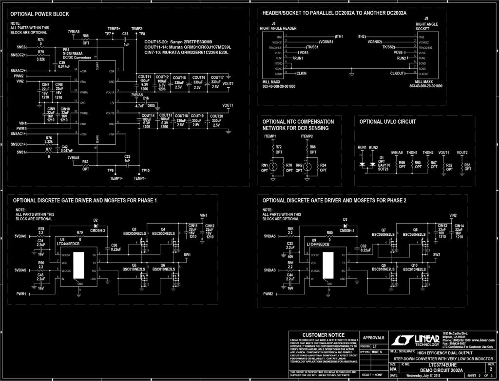
10 Schematic Diagram 10

11 Schematic Diagram Information furnished by Linear Technology Corporation is believed to be accurate and reliable. However, no responsibility is assumed for its use. Linear Technology Corporation makes no representation that the interconnection of its circuits as described herein will not infringe on existing patent rights. 11
12 DEMONSTRATION BOARD IMPORTANT NOTICE Linear Technology Corporation (LTC) provides the enclosed product(s) under the following AS IS conditions: This demonstration board (DEMO BOARD) kit being sold or provided by Linear Technology is intended for use for ENGINEERING DEVELOPMENT OR EVALUATION PURPOSES ONLY and is not provided by LTC for commercial use. As such, the DEMO BOARD herein may not be complete in terms of required design-, marketing-, and/or manufacturing-related protective considerations, including but not limited to product safety measures typically found in finished commercial goods. As a prototype, this product does not fall within the scope of the European Union directive on electromagnetic compatibility and therefore may or may not meet the technical requirements of the directive, or other regulations. If this evaluation kit does not meet the specifications recited in the DEMO BOARD manual the kit may be returned within 30 days from the date of delivery for a full refund. THE FOREGOING WARRANTY IS THE EXCLUSIVE WARRANTY MADE BY THE SELLER TO BUYER AND IS IN LIEU OF ALL OTHER WARRANTIES, EXPRESSED, IMPLIED, OR STATUTORY, INCLUDING ANY WARRANTY OF MERCHANTABILITY OR FITNESS FOR ANY PARTICULAR PURPOSE. EXCEPT TO THE EXTENT OF THIS INDEMNITY, NEITHER PARTY SHALL BE LIABLE TO THE OTHER FOR ANY INDIRECT, SPECIAL, INCIDENTAL, OR CONSEQUENTIAL DAMAGES. The user assumes all responsibility and liability for proper and safe handling of the goods. Further, the user releases LTC from all claims arising from the handling or use of the goods. Due to the open construction of the product, it is the user s responsibility to take any and all appropriate precautions with regard to electrostatic discharge. Also be aware that the products herein may not be regulatory compliant or agency certified (FCC, UL, CE, etc.). No License is granted under any patent right or other intellectual property whatsoever. LTC assumes no liability for applications assistance, customer product design, software performance, or infringement of patents or any other intellectual property rights of any kind. LTC currently services a variety of customers for products around the world, and therefore this transaction is not exclusive. Please read the DEMO BOARD manual prior to handling the product. Persons handling this product must have electronics training and observe good laboratory practice standards. Common sense is encouraged. This notice contains important safety information about temperatures and voltages. For further safety concerns, please contact a LTC application engineer. Mailing Address: Linear Technology 1630 McCarthy Blvd. Milpitas, CA Copyright 2004, Linear Technology Corporation 12 LT 0713 PRINTED IN USA Linear Technology Corporation 1630 McCarthy Blvd., Milpitas, CA (408) FAX: (408) LINEAR TECHNOLOGY CORPORATION 2013
DEMO MANUAL DC1889A. LTM4624EY 4A Step-Down µmodule Regulator. Description. Performance Summary
 Description Demonstration circuit 1889A features the LTM 62EY µmodule regulator, a tiny high performance high efficiency step-down regulator. The LTM62EY has an operating input voltage range of V to 1V
DEMO MANUAL DC1771A LTC3867EUF Synchronous Buck Converter with Remote Sensing DESCRIPTION
 LTC3867EUF Synchronous Buck Converter with Remote Sensing DESCRIPTION Demonstration circuit 1771A is a single output synchronous buck converter featuring the LTC 3867EUF with a 24-lead 4mm 4mm QFN package.
Specifications are at T A = 25 C
 DESCRIPTION Demonstration circuit 1729A is a 2.1A low dropout adjustable linear regulator featuring the LT 3086. The device is designed with multiple features and operates over a wide 1.4V to 40V input
DEMO MANUAL DC1414B-B LTM4601AHV 5V IN to 28V IN, 12A Step-Down µmodule Regulator DESCRIPTION
 LTM4601AHV 5V IN to 28V IN, 12A Step-Down µmodule Regulator DESCRIPTION Demonstration circuit 1414B-B features the LTM 4601AHVEV, the high efficiency, high density switch mode step-down power module. The
Specifications are at T A = 25 C
 DESCRIPTION Demonstration circuit 1737A is a current-mode inverting DC/DC converter featuring the LTC 3863. The board operates from an input range of 4.5V to 16V, and provides a 5.2V, 1.7A output or a
DEMO MANUAL DC1392A LTM4604A 2.375V IN(MIN), 4A Step-Down µmodule Regulator DESCRIPTION
, 4A Step-Down µmodule Regulator DESCRIPTION") LTM4604A 2.375V IN(MIN), 4A Step-Down µmodule Regulator DESCRIPTION Demonstration circuit 1392A features the LTM 4604AEV, the high efficiency, high density switch mode step-down μmodule regulator. The
LTM4604A 2.375V IN(MIN), 4A Step-Down µmodule Regulator DESCRIPTION Demonstration circuit 1392A features the LTM 4604AEV, the high efficiency, high density switch mode step-down μmodule regulator. The
DEMO MANUAL DC1261A LTM V, 1A Step-Down µmodule Regulator DESCRIPTION
 LTM8022 36V, 1A Step-Down µmodule Regulator DESCRIPTION Demonstration circuit 1261A features the LTM 8022 stepdown μmodule regulator delivering a 3.3V output from a 4.5V to 36V input supply. As a step-down
Specifications are at T A = 25 C
 LT3580EDD Boost/ Inverting Regulator DESCRIPTION Demonstration circuits 1144A-A and 1144A-B feature the LT 3580EDD in Boost/Inverting Regulator configurations. The demo circuits demonstrate small size
DEMO MANUAL DC2172A. LTC7138 High Efficiency, High V IN, Step-Down Regulator. Description. Performance Summary
 DEMO MANUAL DC7A Description Demonstration circuit 7A is a high input voltage, 4mA step-down regulator featuring the LTC78. The output of the regulator can be programmed for either 5V,.V or.8v with on-board
Specifications are at T A = 25 C
 DESCRIPTION Demonstration circuit 258A is a 2V, 1.5A micropower synchronous step-down regulator featuring the LT 8608. The demo board is designed for 5V output from a 5.5V to 2V input. The wide input range
DEMO MANUAL DC2171A-B LTM4625 5A Small Footprint Step-Down µmodule Regulator DESCRIPTION PERFORMANCE SUMMARY BOARD PHOTO
 DESCRIPTION Demonstration circuit 7A-B features the LTM 6 µmodule regulator, a tiny low profile high performance step-down regulator. The LTM6 has an operating input voltage range of V to 0V and is able
DEMO MANUAL DC2389A. LTM V, 3A Silent Switcher μmodule Regulator. Description
 Description Demonstration circuit 2389A is a 60V, 3A step-down μmodule regulator featuring the LTM 8073. The demo board is designed for 5V output from a 7V to 60V input. The wide input range allows a variety
DEMO MANUAL DC2129A. LTC3119UFD 18V, 5A Synchronous Buck-Boost DC/DC Converter. Description. Performance Summary Specifications are at T A = 25 C
 Description LTC3119UFD 18V, 5A Synchronous Buck-Boost DC/DC Converter Demonstration circuit 2129A features the LTC 3119, an 18V, 5A synchronous buck/boost DC/DC converter. The DC2129A has been designed
Specifications are at T A = 25 C
 DEMO MANUAL DCA Description LT871 Synchronous Four-Quadrant Converter Demonstration circuit A is a synchronous fourquadrant converter featuring the LT 871 switching controller. The LT871 can regulate to
DEMO MANUAL DC1453A LTM4619EV: 4.5V-28V, Dual 4A Step-Down µmodule Regulator DESCRIPTION
 DEMO MANUAL DC5A LTM69EV:.5V-8V, Dual A Step-Down µmodule Regulator DESCRIPTION Demonstration circuit 5A features the LTM 69EV, the high input voltage, high effi ciency, high density, dual A step-down
Specifications are at T A = 25 C
 DEMO MANUAL DC66A LT590 48V Buck-Mode LED Driver WARNING! DO NOT LOOK DIRECTLY AT OPERATING LED This Circuit Produces Light that Can Damage Eyes. DESCRIPTION Demonstration circuit 66A is a 48V Buck-Mode
DEMO MANUAL DC1560A LTM8048 Isolated µmodule DC/DC Converter with LDO Post Regulator DESCRIPTION BOARD PHOTO
 DESCRIPTION Demo circuit 156A is an isolated flyback μmodule DC/DC converter with LDO post regulator featuring LTM 848. The demo circuit is designed for a 6V flyback output and a 5V post regulator output
I LOAD LOAD R IN V + LT6110 IMON DC2033 F01. Figure 1. One Cable/Wire Compensation (One Wire to a Load Sharing the Regulator s Ground) LT6110
 LT6110") + Description The DC2033A demo board features the LT 6110 cable/ wire drop compensator IC. The is a precision high side current sense that monitors load current via a sense resistor and converts the sense
+ Description The DC2033A demo board features the LT 6110 cable/ wire drop compensator IC. The is a precision high side current sense that monitors load current via a sense resistor and converts the sense
DEMO MANUAL DC1425A LTC3859AIFE Triple Output Synchronous Step-Up/Dual Step-Down Supply DESCRIPTION
 LTC3859AIFE Triple Output Synchronous Step-Up/Dual Step-Down Supply DESCRIPTION Demonstration circuit DC1425A is a triple output synchronous step-up/dual step-down supply featuring the LTC 3859AIFE. The
DEMO MANUAL DC2257A LTM V IN, 38V OUT Boost µmodule LED Driver with 40V Switch DESCRIPTION BOARD PHOTO
 DESCRIPTION Demonstration circuit 2257A features the LTM 8005 a 38V IN, 38V OUT boost μmodule LED driver that can disconnect the output to protect against faults and provides spread spectrum switching
Specifications are at T A = 25 C. PARAMETER CONDITIONS/NOTES VALUE Input Voltage Range, V IN (BSTIN) 3V to 30V (See Table 1) I LED
 3V to 30V (See Table 1) I LED") DESCRIPTION Demonstration circuits 1511A-A and 1511A-B feature the LTM 8042 and the LTM8042-1, which are respectively complete 1A and 350mA µmodule LED drivers. The demonstration circuits are assembled
DESCRIPTION Demonstration circuits 1511A-A and 1511A-B feature the LTM 8042 and the LTM8042-1, which are respectively complete 1A and 350mA µmodule LED drivers. The demonstration circuits are assembled
Specifications are at T A = 25 C
 Description LT3042EDD 20V, 200mA, Ultralow Noise Ultrahigh PSRR RF LDO Regulator DC2246A is a linear regulator featuring the LT 3042EDD, which is a 200mA, ultralow noise, and ultrahigh power supply rejection
DEMO MANUAL DC1307B LTM8027: 60V, 4A DC/DC µmodule Regulator Description
 LTM807: 60V, 4A DC/DC µmodule Regulator Description Demonstration circuit 07B features the LTM 807 configured to deliver V from a 6V to 60V input. The wide input range of the LTM807 allows a variety of
Specifications are at T A = 25 C
 DEMO MANUAL DC548A Description Demonstration circuit 548A is an active rectifier with reverse protection featuring the LT 867. The demo board is designed for 5A load current. The input voltage range of
DEMO MANUAL DC1743A LTM4613 8A, High Voltage Power µmodule Regulator Description
 DEMO MANUAL DC74A LTM46 8A, High Voltage Power µmodule Regulator Description Demonstration circuit DC74A features the LTM 46EV, an EN550 class B certified, high input and output voltage, high efficiency,
Specifications are at T A = 25 C
 LTC3245EMSE Wide V IN Range, Low Noise 250mA Buck-Boost Charge Pump Description Demonstration circuit DC1802A is a wide V IN range, low noise, 250mA buck-boost charge pump featuring the LTC 3245EMSE. Design
DEMO MANUAL DC2568A LTM4622A Ultrathin Dual 2A Step-Down µmodule Regulator DESCRIPTION BOARD PHOTO
 DESCRIPTION Demonstration circuit 568A features the LTM 46A µmodule regulator, a tiny low profile high performance high efficiency dual step-down regulator. The LTM46A has an operating input voltage range
Specifi cations are at T A = 25 C. PARAMETER CONDITIONS VALUE Maximum Input Voltage
 DESCRIPTION The demo circuit 7A is a dual current mode PWM step-down DC/DC converter featuring LT 99. The demo circuit is designed for V and.v outputs from a 7V to 60V input. The current capability of
DEMO MANUAL DC2141A LTM A DC/DC Step-Down µmodule Regulator DESCRIPTION BOARD PHOTO
 DESCRIPTION Demonstration circuit A features the LTM 67EY, a A high efficiency, switch mode step-down power µmodule regulator. The input voltage range is from 6V to 5V. To use DCA for input voltage range
Specifications are at T A = 25 C
 LTC6090 High Voltage CMOS Amplifier Description Demonstration circuit 1979A is a high voltage CMOS amplifier featuring the LTC 6090. An onboard isolated flyback converter provides ±62V power to the LTC6090
OUT to. Specifications are at T A = 25 C. PARAMETER CONDITIONS MIN TYP MAX UNITS Input Voltage V Output Voltage
 DESCRIPTION LT80 Micropower No-Opto Isolated Flyback Converter with 50V/A Switch Demonstration circuit 9A is a micropower no-opto isolated flyback converter featuring the LT 80. This demo circuit outputs
Specifications are at T A = 25 C
 Description Demonstration circuit 0A is a V, A micropower synchronous step-down Silent Switcher with spread spectrum frequency modulation featuring the LT 860. The demo board is designed for V output from
DEMO MANUAL DC2013A. LT3952EFE 60V LED Driver with Internal 4A Switch. Description
 Description Demonstration Circuit DC2013A is a 60V LED driver with internal 4A switch featuring the LT 3952 monolithic LED driver. It accepts an input voltage from 5V to 36V (with transient to 42V) and
DEMO MANUAL DC1797A LTC3536 1A, Low Noise, Wide V IN Buck-Boost DC/DC Converter Description
 DEMO MANUAL DC797A LTC56 A, Low Noise, Wide V IN Buck-Boost DC/DC Converter Description Demonstration circuit 797A is a combined step-up and step-down DC/DC converter using the LTC 56 monolithic synchronous
Specifications are at T A = 25 C. PARAMETER CONDITIONS MIN TYP MAX UNITS Input Voltage Range V Output Voltage
 DESCRIPTION Demonstration circuit 1694B is an isolated flyback converter featuring the LT 748. The demo circuit is designed for a 12V output from a 22V to 75V DC input. The output current is up to 2.5A.
DEMO MANUAL DC2020A LT3955EUHE 60V IN 80V OUT LED Driver. Description
 LT3955EUHE 60V IN 80V LED Driver Description Demonstration circuit 2020A is a 60V IN, 80V LED driver. It generates its own PWM waveform from its internal PWM generator for accurate PWM dimming with up
DEMO MANUAL DC2079A LT V IN 40V OUT LED Driver. Description
 LT3954 40V IN 40V LED Driver Description Demonstration circuit 2079A is a 40V IN, 40V LED driver. It generates its own PWM waveform from its internal PWM generator for accurate PWM dimming with up to 33:1
Specifications are at T A = 25 C
 DESCRIPTION LTC65EDHC Low Noise Dual Supply with Boost and Inverting Charge Pumps Demonstration Circuit 5A has boost and inverting charge pumps each with a low noise LDO post regulator featuring the LTC
DEMO MANUAL DC1083A-A LTM4603 Synchronizable 20V, 6A Step-Down µmodule Regulator DESCRIPTION
 LTM460 Synchronizable 0V, 6A Step-Down µmodule Regulator DESCRIPTION Demonstration circuit DC08A-A features the LTM 460, the high efficiency, high density step-down μmodule regulator. The input voltage
NUMBER DEMO CIRCUIT NUMBER DESCRIPTION
 DEMO MANUAL DC9A LTC66 Fully Differential Amplifier Description The LTC 66 is a low power, low noise differential op amp with rail-to-rail output swing and good DC accuracy. The amplifier may be configured
DEMO MANUAL DC2473A LTC6419 Dual Differential Amplifier/ADC Driver DESCRIPTION
 DESCRIPTION Demonstration circuit 7A features the LTC 9 Dual Differential Amplifier/ADC Driver. It incorporates a variety of passive components to support configurations for varied applications. These
DEMO MANUAL DC2328A LTM4651 EN55022B Compliant 58V, 24W Inverting-Output DC/DC µmodule Regulator
 Description DEMO MANUAL DC8A LTM465 EN550B Compliant 58V, 4W Inverting-Output DC/DC µmodule Regulator Demonstration circuit 8A is an inverting buck-boost converter with V to 4V input voltage, 4V output
Specifications are at T A = 25 C
 DESCRIPTION Demonstration circuit 0A is a A, bidirectional charger/ regulator featuring the LTC 6, a bidirectional synchronous step-up charger and step-down converter. DC0A implements backup by charging
Specifications are at T A = 25 C
 DESCRIPTION Demonstration circuit 23A is a 42V, 6A micropower synchronous step-down second generation Silent Switcher with spread spectrum frequency modulation featuring the LT864S. The demo board is designed
DEMO MANUAL DC2247A LT V 2A Synchronous 2MHz Boost LED Driver. Description
 Description Demonstration circuit DC2247A is a 36V 2A synchronous 2 boost LED driver featuring the LT 3922. It drives a single string of LEDs at 3mA up to 34V when V IN is between 7V and 28V. It runs down
DEMO MANUAL DC780B Constant-Current/ Constant-Voltage 1.4MHz Step-Up DC/DC Converter DESCRIPTION
 Constant-Current/ Constant-Voltage.MHz Step-Up DC/DC Converter DESCRIPTION Demonstration circuit 780B is a Constant-Current Constant- Voltage.MHz Step-up DC/DC Converter featuring the LT 68. DC780B demonstrates
DEMO MANUAL DC1588A LTM4611EV: Ultralow V IN 15A Step-Down Power µmodule Regulator DESCRIPTION PERFORMANCE SUMMARY BOARD PHOTO
 DESCRIPTION Demonstration circuit DC88A features the LTM 6EV, a low input voltage A step-down power module. The operating input voltage range is.v to.v with an output voltage range from 0.8V to V. DC88A
DEMO MANUAL DC241B LTC1535 Full Duplex, Isolated RS485 Transceiver with Slew Limiting DESCRIPTION
 DESCRIPTION Demonstration circuit 241B showcases the LTC 1535 isolated RS485 transceiver. The LTC1535 features 2,500V isolation; the left-half of the chip contains familiar RS485 logic functions and an
DEMO MANUAL DC777A LTC Bit Rail-to-Rail V OUT DAC DESCRIPTION PERFORMANCE SUMMARY
 LTC2601 16-Bit Rail-to-Rail V OUT DAC DESCRIPTION Demonstration circuit DC777A features the LTC 2601 16-bit DAC. This device establishes a new board-density benchmark for 16-bit DACs and advances performance
DEMO MANUAL DC579A LTC2600 Octal 16-Bit DAC DESCRIPTION PERFORMANCE SUMMARY BOARD PHOTO
 LTC2600 Octal 16-Bit DAC DESCRIPTION Demonstration circuit 579A features the LTC2600 octal 16-bit DAC. This device establishes a new board density benchmark for 16-bit DACs and advances performance standards
DEMO MANUAL DC2468A LT8645S 65V, 8A Micropower Synchronous Step-Down Silent Switcher 2 DESCRIPTION
 DESCRIPTION Demonstration circuit 2468A is a 6V, 8A micropower synchronous step-down second generation Silent Switcher with spread spectrum frequency modulation featuring the LT864S. The demo board is
Specifications are at T A = 25 C
 Description Demonstration circuit 1961A features the LT 8309, a secondary synchronous driver in an isolated, no optocoupler, flyback converter. It regulates a 12V, 5A output from a 36V to 72V input source.
DEMO MANUAL DC1477A LTM4609EV: 36V IN, 34V OUT Buck-Boost DC/DC µmodule Regulator DESCRIPTION
 LTM4609EV: 6V IN, 4V OUT Buck-Boost DC/DC µmodule Regulator DESCRIPTION Demonstration circuit DC1477A features the LTM 4609EV, a high voltage, high efficiency, high density switch mode buck-boost power
DEMO MANUAL DC1498A LTM4620EV High Efficiency, Dual 13A Step-Down Power µmodule Regulator Description
 DEMO MANUAL DC98A LTM6EV High Efficiency, Dual A Step-Down Power µmodule Regulator Description DC98A features the LTM 6EV, the high efficiency, high density, dual A, switch mode step-down power module
DEMO MANUAL DC1181B LTM4608: Low V IN, 8A DC/DC µmodule with Tracking, Margining and Frequency Synchronization DESCRIPTION
 LTM4608: Low V IN, 8A DC/DC µmodule with Tracking, Margining and Frequency Synchronization DESCRIPTION Demonstration circuit DC8B features the LTM 4608EV, the high efficiency, high density switch mode
DEMO MANUAL DC1780A-B. LTM4620EV: High Efficiency, PolyPhase 75A Step-Down Power µmodule Regulator DESCRIPTION BOARD PHOTO
 DEMO MANUAL DC780A-B DESCRIPTION Demonstration circuit 780A-B features PolyPhase design using the LTM 60EV, the high efficiency, high density, dual A, switch mode step-down power module regulator. The
DEMO MANUAL DC2345A LT8391EFE 60V Synchronous 4-Switch Buck-Boost Led Controller with Spread Spectrum
 DESCRIPTION DEMO MANUAL DC2345A LT8391EFE 60V Synchronous 4-Switch Buck-Boost Led Controller with Spread Spectrum Demonstration circuit 2345A is a 60V synchronous 4-switch buck-boost LED controller with
DEMO MANUAL DC1319B-A/DC1319B-B LT3756-2/LT High Voltage LED Controller DESCRIPTION
 LT3756-2/LT3756-1 High Voltage LED Controller DESCRIPTION Demonstration circuit 1319B-A/1319B-B is a high voltage and high current LED driver controller. The V IN pin input voltage is as high as 100V,
DEMO MANUAL DC1660B LTC GHz Low Noise Differential 16-Bit ADC Buffer Description
 DEMO MANUAL DC66B LTC67.6GHz Low Noise Differential 6-Bit ADC Buffer Description Demonstration circuit 66B features the LTC 67 differential 6-bit ADC buffer. The demo board incorporates a variety of passive
DEMO MANUAL DC823B-B LTM4600HV: 28V, 10A Step-Down Power µmodule Regulator DESCRIPTION
 DEMO MANUAL DC8B-B LTM4600HV: 8V, 0A Step-Down Power µmodule Regulator DESCRIPTION Demonstration circuit DC8B-B features the LTM 4600HVEV, a 0A high efficiency, high density switch mode step-down power
DEMO MANUAL DC1923A LTC V, 200mA Synchronous Buck-Boost DC/DC Converter with 1.3µA Quiescent Current
 Description DEMO MANUAL DC9A LTC9- V, 00mA Synchronous Buck-Boost DC/DC Converter with.µa Quiescent Current Demonstration circuit 9A features the LTC9-, a high efficiency 00mA buck-boost DC/DC converter
DEMO MANUAL DC1646A LTC GHz RF Power Detector with Comparator Description
 LTC556 15GHz RF Power Detector with Comparator Description The demonstration circuit 166A features the LTC 556, an UltraFast RF peak detector with a built in gain-selectable high speed operational amplifier
DEMO MANUAL DC961B LT1994 Low Noise, Low Distortion, Fully Differential Amplifier/Driver. Description
 Description Demonstration circuit 9 features an LT 99, low noise, low distortion, fully differential amplifier. The LT99 is a high precision, very low noise, low distortion, fully differential input/output
DEMO MANUAL DC1666A LT3791 Four-Switch Buck-Boost LED Driver Controller. Description
 Description Demonstration circuit DC1666A is a synchronous fourswitch buck-boost LED driver controller. It accepts an input voltage from 4.7V to 60V, and drives up to 25V of LEDs at 2A. DC1666A features
DEMO MANUAL DC1744A LT3799 Offline Isolated Flyback LED Driver with PFC Description
 LT3799 Offline Isolated Flyback LED Driver with PFC Description Demonstration circuit 1744A is an off-line isolated flyback converter featuring the LT 3799. The demo board is designed to drive a single
Specifications are at T A = 25 C
 DEMO MANUAL DC7A DESCRIPTION Demonstration circuit DC7A is a DC/DC synchronous boost converter featuring the LTC 79 constant frequency current mode synchronous boost controller. The DC7A generates a 8V
DEMO MANUAL DC1503A. LTM2881: Isolated 20Mbps RS485/RS422 µmodule Transceiver with Power DESCRIPTION OPERATING PRINCIPLES
 DEMO MANUAL DC50A DESCRIPTI Demonstration circuit DC50A is an Isolated RS85/ RS μmodule transceiver + power featuring the LTM 88. The demo circuit is a 500V RMS galvanically isolated RS85/RS transceiver
DEMO MANUAL DC1437B LTM9003 Digital Predistortion Receiver Subsystem. Description. Connection Diagram
 Description Demonstration circuit 1437B is an evaluation board featuring Linear Technology Corporation s LTM 9003 12-Bit Predistortion Receiver Subsystem. DC1437 demonstrates good circuit layout techniques
DEMO MANUAL DC1922A LTC V, 200mA Synchronous Buck-Boost DC/DC Converter with 1.3µA Quiescent Current
 Description DEMO MANUAL DC9A LTC9 5V, 00mA Synchronous Buck-Boost DC/DC Converter with.µa Quiescent Current Demonstration Circuit 9A features the LTC 9, a high efficiency 00mA buck-boost DC/DC converter
DEMO MANUAL DC1746A LTM2881: Isolated RS485/RS422 µmodule Transceiver + Power DESCRIPTION
 LTM2881: Isolated RS485/RS422 µmodule Transceiver + Power DESCRIPTION Demonstration circuit 1746A is an isolated RS485/RS422 μmodule transceiver + power featuring the LTM 2881. The demo circuit is a 2500V
DEMO MANUAL DC1964A LTC3110 2A, Bidirectional Buck-Boost DC/DC Regulator and Charger/Balancer Description
 DEMO MANUAL DC96A LTC0 A, Bidirectional Buck-Boost DC/DC Regulator and Charger/Balancer Description Demonstration circuit 96A is a A, bidirectional buckboost DC/DC regulator and charger/balancer, featuring
Specifications are at T A = 25 C
 Description Demonstration circuit 39A is a High Efficiency Switching Surge Stopper and EMI Filter featuring the LTC 7860. The board operates from an input range of 3.5V to 60V, provides a 3.5V to 7.V output
Specifications are at T A = 25 C
 Description DC184 is a dual output buck and inverting converter. It provides V and V power from 6V to 32V input. The V output can source up to 1.4 load current and the V output can source up to 800m load
DEMO MANUAL DC2349A LTC5586 6GHz High Linearity I/Q Demodulator with Wideband IF Amplifier DESCRIPTION BOARD PHOTO
 DESCRIPTION Demonstration circuit 2349A showcases the LTC 5586 wideband high linearity IQ demodulator with IF amplifier. The Linear Technology USB serial controller, DC590B, is required to control and
DEMO MANUAL DC1182A LTC2981: I 2 C Programmable Precision Reference with EEPROM DESCRIPTION
 DESCRIPTION Demonstration circuit 8A features the LTC 98, a precision reference that can be programmed through an easy-to-use I C interface. While external pins or internal register bits select the central
DEMO MANUAL DC573A LTC Bit Micropower No Latency Delta Sigma ADC DESCRIPTION BOARD PHOTO
 DESCRIPTION This demonstration board features the LTC 00, a -bit high performance ΔΣ analog-to-digital converter (ADC). The LTC00 combines exemplary DC accuracy (INL ±ppm,.μv offset, 0.ppm noise) with
DEMO MANUAL DC2158A LTC MHz to 40GHz RMS Power Detector
 LTC5596 00MHz to 0GHz RMS Power Detector Description Demonstration circuit 58A hosts a high accuracy RMS Power Detector featuring the LTC 5596 IC. This device is a wide dynamic range RMS RF Power Detector
Specifications are at T A = 25 C
 DESCRIPTION Demonstration circuit 47A is intended to demonstrate the performance of the LTC4367 00 overvoltage (O), undervoltage (U), and reverse supply protection controller. This controller protects
DEMO MANUAL DC1893A LT3697 USB 5V, 2.5A Output, 35V Input with Cable Drop Compensation DESCRIPTION
 DESCRIPTION Demonstration circuit 89A is a USB 5V,.5A output, 5V input buck with cable drop compensation featuring the LT 697. The LT697 is a step-down switching regulator designed to power 5V USB applications.
DEMO MANUAL DC2457A LT8390EUFD 60V Low EMI Synchronous 4-Switch Buck-Boost Voltage Regulator. Description
 Description Demonstration circuit DC2457A is a 12V, 4A, 4-switch synchronous buck-boost regulator featuring low EMI noise and small footprint. It runs at 4kHz switching frequency. Spread spectrum frequency
DEMO MANUAL DC1561B LTC4278: PoE+ (802.3at) Powered Device Controller and Synchronous Flyback Description
 Powered Device Controller and Synchronous Flyback Description") LTC4278: PoE+ (802.3at) Powered Device Controller and Synchronous Flyback Description Demonstration circuit 1561B is a high power supply, featuring the LTC 4278. This board is a Type 2 (IEEE 802.3at) compliant,
LTC4278: PoE+ (802.3at) Powered Device Controller and Synchronous Flyback Description Demonstration circuit 1561B is a high power supply, featuring the LTC 4278. This board is a Type 2 (IEEE 802.3at) compliant,
Specifications are at T A = 25 C
 Description Demo circuit 574 is a high efficiency, high frequency step-down converter incorporating the LTC 6 monolithic synchronous regulator. The DC574A has an input voltage range of.5v to 5.5V and is
DEMO MANUAL DC1554A LTM2882 Dual Isolated RS232 µmodule Transceiver with Integrated DC/DC Converter DESCRIPTION OPERATING PRINCIPLES
 DESCRIPTI Demonstration circuit DCA is a dual isolated RS μmodule transceiver with integrated power featuring the LTM 88. The demo circuit provides -channel, 00 RMS, galvanically isolated RS transceiver
DEMO MANUAL DC941A LTC Bit Σ ADC with Easy Drive Input Current Cancellation. Description. Quick Start Procedure
 Description Demonstration circuit 9A features the LTC, a -bit high performance Δ analog-to-digital converter (ADC). The LTC features ppm linearity, 0.μV offset, and 00nV RMS noise. The input is fully differential,
DEMO MANUAL DC2117A. LTC3895EFE High Input Voltage Synchronous Buck Converter DESCRIPTION PERFORMANCE SUMMARY
 DEMO MANUAL DC7A DESCRIPTION LTC89EFE High Input Voltage Synchronous Buck Converter Demonstration circuit 7A is a single output high voltage nonisolated synchronous step-down converter that drives all
DEMO MANUAL DC2153A LTC MHz to 1700MHz Differential ADC Driver/IF/RF Amplifier. Description
 Description Demonstration circuit 2153A features the LTC6430-15 differential ADC/IF Amplifier. The LTC6430-15 has a power gain of 15.2dB and is part of the LTC6430-YY amplifier series. The DC2153A demo
DEMO MANUAL DC2180A. LTC4371 Dual Negative Voltage Ideal Diode-OR Controller. Description. Performance Summary
 DEMO MANUAL DC80A Description Demonstration circuit 80A showcases the LTC 47 dual negative voltage ideal diode-or controller and monitor, in a 48V, 50A application. Each channel includes two paralleled
DEMO MANUAL DC2543A LTC7820EUFD High Efficiency, Charge Pump DC/DC Converter. Description. Performance Summary
 Description Demonstration circuit A is a high efficiency, high density, open loop charge pump (inductorless) DC/DC converter. This demo board is a voltage divider which achieves a : step-down ratio from
DEMO MANUAL DC1563A. LTC2315/LTC2314/LTC2313/LTC2312/ 12-Bit/14-Bit, 5Msps/4.5Msps/ 2.5Msps/500ksps/Serial, High Speed SAR ADCs DESCRIPTION
 LTC2315/LTC2314/LTC2313/LTC2312/ 12-Bit/14-Bit, 5Msps/4.5Msps/ 2.5Msps/500ksps/Serial, High Speed SAR ADCs DESCRIPTION Demonstration circuit 1563A features the LTC 2315 family. With sample rates up to
DEMO MANUAL DC2513A LTC7821EUH High Density Hybrid Step-Down Synchronous Converter. Description. Performance Summary
 Description Demonstration circuit A is a high efficiency, high power density hybrid converter. It can deliver V/A with an input voltage from V to V. This demo board features the LTC, which uses an architecture
DEMO MANUAL DC1816A LT Offline Isolated Flyback LED Driver with PFC DESCRIPTION
 LT3799-1 Offline Isolated Flyback LED Driver with PFC DESCRIPTION Demonstration circuit 1816A is an off-line isolated flyback LED driver featuring LT 3799-1. The demo board provides a single constant current
DEMO MANUAL DC2424A LT V Synchronous Dual LED Driver with I 2 C DESCRIPTION
 DESCRIPTION The is a V synchronous dual LED driver with I C featuring the LT 94. It drives two separate LEDs (or channels of LEDs) at A when V IN is between V and V. runs at MHz switching frequency. Its
DEMO MANUAL DC1817B LT3798 Isolated No Opto-Coupler Flyback Controller with PFC Description
 DEMO MANUAL DC87B LT798 Isolated No Opto-Coupler Flyback Controller with PFC Description Demonstration circuit 87B is an off-line isolated flyback converter featuring the LT 798. The demo board provides
DEMO MANUAL DC2456A LTC3779 High Voltage, High Efficiency 48V/10A Synchronous Buck-Boost Converter
 Description DEMO MANUAL DC6A LTC779 High Voltage, High Efficiency 8V/0A Synchronous Buck-Boost Converter Demonstration circuit 6A is a high voltage, high efficiency synchronous buck-boost DC/DC converter
DEMO MANUAL DC2641A LTC7801EUFD High Input Voltage Synchronous Buck Converter DESCRIPTION PERFORMANCE SUMMARY
 DESCRIPTION Demonstration circuit 6A is a single output synchronous buck converter featuring the LTC780EUFD in the -lead QFN package. The input voltage range is from 6V to 00V and the output is V/0A. The
LTC3610EWP DESCRIPTION
 LTC3610EWP DESCRIPTION Demonstration circuit DC119A is a synchronous step down converter featuring the LTC 3610, the high efficiency, high density DC/DC regulator. The input voltage range is from 4.5V
DEMO MANUAL DC2134A LTC4020EUHF High Power Buck-Boost Multi-Chemistry Battery Charger. Description. Performance Summary
 Description Demonstration circuit A is a high power buck-boost multichemistry battery charger featuring the LTC. The board will accept an input voltage between V and V. The float voltage of the battery
DEMO MANUAL DC1785B LTC2991 I 2 C Temperature, Voltage and Current Monitor. Description
 Description Demonstration circuit 78B features the LTC 99, a high performance temperature, voltage and current monitor that uses an I C interface for communication. It offers sub-millivolt voltage resolution,
DEMO MANUAL DC1790A LTM2886 SPI/Digital or I 2 C µmodule Isolator with Fixed ±5V and Adjustable 5V Regulated Power
 Description DEMO MANUAL DC90A LTM88 SPI/Digital or I C µmodule Isolator with Fixed ±V and Adjustable V Regulated Power Demonstration circuit 90A is a serial peripheral interface bus (SPI) or inter-ic bus
DEMO MANUAL DC1924A LT V V IN and V OUT Synchronous 4-Switch Buck-Boost DC/DC Controller DESCRIPTION
 DESCRIPTION Demonstration circuit 9A is a high performance buckboost converter featuring the LT 7 that can operate from input voltages above, below or equal to the output voltage. The demo board input