How to Build Advanced Short Wave Receivers R. A. PENFOLD
|
|
|
- Charleen Shields
- 5 years ago
- Views:
Transcription
1 How to Build Advanced Short Wave Receivers R. A. PENFOLD 1
2 HOW TO BUILD ADVANCED SHORT WAVE RECEIVERS
3 HOW TO BUILD ADVANCED SHORT WAVE RECEIVERS by R. A. PENFOLD BERNARDS (Publishers) LTD The Grampians Shepherds Bush Road London W6 7NF England
4 Although every care is taken with the preparation of this book, the publishers or author will not be responsible in, any way for any errors that might BERNARDS (Publishers) LTD I.S.B.N First Published June 1977 Printed and Manufactured in Great Britain by Hunt Barnard Printing Ltd.
5 CONTENTS Page CHAPTER ONE - ADVANCED S.W. RECEIVERS Superhet Principle Drawbacks Basic S.W. Superhet Receiver Padder Capacitors I.F. Stages A.G.C. Action Audio Stages B.F.O General Points Chassis & Panel Mixer Wiring I.F. Amplifler Wiring Audio Stages B.F.O. Unit Alignment Using the Set CHAPTER TWO - MODULAR SUPERHET Image Rejection R.F. Amplifiers Jugfet Amplifier MOSFET Amplifier Bandpass input Mixer/Osc. Stages Alternative Oscillator I.F. Amplifier A.F. Amplifiers Class A Circuit B.F.O F.E.T./Varicap B.F.O Adjustment
6 CHAPTER THREE - DOUBLE CONVERSION RECEIVER Alternative System nd Mixer/Osc. Circuit Adjustments Bandswitching CHAPTER FOUR - ADD-ON CIRCUITS Q Multiplier Adjustment Crystal Filter Adjustment Mechanical Filters S Meter Adjustment Noise Limiter C.W. Filter Variable Notch Filter Product Detector Mains P.S.U Crystal Calibrator Using the Calibrator Preselector Semiconductor Leadout Data Special Note for Overseas Readers
7 CHAPTER ONE ADVANCED S.W. RECEIVERS Although there is a tendency for short wave listeners and Radio Amateurs to use ready made equipment these days, greater satisfaction and enjoyment can be gained from the hobby by using home constructed equipment. Using ready made S.W. gear does not give any insight into the way in which the apparatus functions, and by building ones own equipment it is virtually inevitable that a reasonable understanding of the techniques involved will be grasped. Such an understanding is very helpful when it comes to actually using a finished receiver, and it enables the operator to obtain optium results from the set. The reason that commercially produced equipment has increased in popularity is probably largely due to the high standard of finish that is achieved. It must be admitted that it is difficult for the home constructor to equal commercial standards in this respect, but if due care and attention is taken, it is possible to obtain a standard which. will satisfy even the most critical. As far as performance is concerned, there is absolutely no reason why a home constructed receiver should not have a level of performance which is at least equal to that of a commercially built receiver of similar complexity. Further. more, the home constructed receiver is likely to cost very much less than its ready made equivalent. Superhet Principle The receiver circuits which are featured in this book are all of the superheterodyne (usually abbreviated to superhet) type, 7
8 and circuits of the simpler T.R.F. type will not be considered here. These circuits do not really make good projects for those who have no or only very little experience of S.W. Receiver construction, with the exception of the first project that is described. Anyone who has tackled a simple T.R.F. S.W. receiver should be able to construct and align this set without too much difficulty, and the primary reason for its inclusion is that it makes a good introduction to superhet designs. Once some experience has been gained with this set, the constructor should be fully competent to go on and build any of the more advanced designs which are described in subsequent chapters of this book. Apart from providing a good introduction to S.W. superhets, this set also makes a very interesting project in its own right. Before going on to consider some practical circuits, some back ground information will be given. It must be stressed that while some of this is of purely an academic nature, some of this is really essential knowledge for anyone undertaking construction of a superhet receiver. This is particularly the case when it comes to the basic principle of the superhet. Having an understanding of the function of each stage of a superhet makes it easy to put together a practical circuit with confidence. Perhaps more importantly, it takes the guesswork out of aligning and using a finished receiver, A superhet differs from a straight or T.R.F. receiver in that in the case of the latter, all processing of the signal prior to detection takes place at whatever frequency the signal happens to be at. In the case of a superhet the input signal is converted to an intermediate frequency (I.F.) where it is considerably amplified prior to detection. In a conventional superhet the I.F. is fixed, and no matter what the frequency of the input signal is, it is converted to the intermediate frequency using the heterodyne principle. It is from this that the name superhet is derived. 8
9 9
10 A block diagram which illustrates the basic arrangement of a simple superhet is shown in Figure 1. The aerial signal is coupled to a tuned circuit which tunes the desired frequency and rejects all others. The selected signal is then coupled to one input of a mixer, and the other input of the mixer is fed from an oscillator. There will be four output signals from the mixer, and these are as follows:- 1. The aerial signal. 2. The oscillator signal. 3. The sum of these two frequencies. 4. The difference frequency of the two input signals. It will be apparent from this that two new frequencies are produced, apart from the original input frequencies. Either of these can be used to provide the I.F. signal, but conventionally it is the difference signal which is used. A simple mathematical example should help to clarify the function of the mixer and oscillator stages. Suppose that the receiver is required to tune over the range of 5 to 10MHZ, and that an intermediate frequency of 470kHZ is used (the standard intermediate frequency for British transistorised superhets). In order to achieve this it is necessary to arrange the input tuned circuit to tune over a range of 5-10MHZ, with the oscillator tuning over a range of 5.47 to 10.47MHZ. In other words the oscillator is always.47mhz (which is the same as 470kHZ) higher than the input signal frequency. It is not only necessary to have this relationship at band limits, but it must be maintained throughout the tuning range. Thus if the set is tuned to receive a signal at, say, 7.5MHZ, the oscillator will be at a frequency of 7.97MHZ. This produces the following four output frequencies from the mixer: MHZ MHZ MHZ ( MHZ) kHZ ( MHZ). 10
11 It is obviously the last of these which is used as the I.F. signal, and the I.F. amplifier will reject the other three signals which are well outside its passband. The I.F. amplifier provides a considerable level of gain, and unlike a T.R.F. set, only a relatively low level of audio gain is required. The detector is a conventional diode type usually. At first sight the superhet may appear to be a rather overcomplicated setup which offers little advantage, if any, over a T.R.F. design. In fact this is not the case, and even a fairly simple superhet can usually out perform a good T.R.F. design. The reasons for this are quite straightforward. The two main requirements of a S.W. receiver are for high sensitivity and good selectivity. In order to obtain high sensitivity it is necessary to employ a high degree of R.F. amplification. In order to obtain good selectivity it is necessary to use several tuned circuits. This is rather difficult to achieve with a T.R.F. design since every tuned circuit will need a tuning capacitor. This, coupled with the fairly high frequencies involved makes high gain rather difficult to achieve, as extensive screening would be required in order to eliminate stray feedback and the instability which would accompany it. Tuned circuits operating at frequencies in the region of tens of MHZ tend to have rather wide bandwidths, and so even by using a number of tuned circuits a very high degree of selectmty would not be obtained. These difficulties are overcome by using the superhet technique. High gains are not involved at the signal frequency, since the purpose of the early stages of the set is merely to convert the signal to the I.F., and not to provide any significant gain. Obtaining good stability is not, therefore, too much of a problem. It is only necessary to use a twin gang tuning capacitor, with one section being used for the tuning of the aerial tuned circuit, and the other one for the oscillator tuning. 11
12 It is when we come to the I.F. amplifier that the main advantages of the superhet become apparent. The comparatively low frequency means that even using only a few tuned circuits results in quite good selectivity. It is a simple matter to achieve high gain and stability, this again being aided by the comparatively low frequency. It is necessary to screen the tuning coils and their tuning capacitors if a very high level of gain is used, but since this amplifier only operates at a single frequency, the tuning capacitance is provided by a fixed capacitor. The coil and capacitor can therefore be a single component which is contained in a metal screening can. Another advantage of having this single frequency amplifier is that a very high degree of selectivity can be obtained by the use of crystal, mechanical, or ceramic I.F. filters. A common factor to all three of these types of filter is that they can only be used at a single frequency. This makes them completely unsuitable for use with a T.R.F. receiver. Drawbacks As one would probably expect, the superhet is not without a few drawbacks. One minor one is that aerial signals at a frequency of 470kHZ can sometimes break through to the I.F. stages. However, this rarely causes any significant trouble, and it can be eliminated by using a wavetrap in the aerial lead. This merely consists of a simple L - C circuit which has a high impedance at and around the I.F., but which has a low impedance at other frequencies. Thus it does not hinder the S.W. aerial signals, but it blocks the interfering signals at the intermediate frequency. The main problem with superhets is what is known as the image signal or the image response. Superhet receivers actually operate on two frequencies at once, the main response and the image response. In our previous mathematical example the main response was 7.5MHZ, and was produced by an oscillator frequency of 7.97MHZ and an ordinary I.F. of 470kHZ. 12
13 The 470kHZ I.F. signal was produced by the oscillator and aerial signals difference frequency ( = 0.47MHZ). If an aerial signal at 8.44MHZ were to break through to the input of the mixer, this would also produce a 470kHZ I.F. signal (8.44MHZ MHZ = 0.47MHZ). It is this signal which is the image response. As may already be apparent, the oscillator does not have to be above the aerial signal frequency, but it can be below the input signal frequency. In either case the difference between the two frequencies is equal to the I.F. It is the current convention that the oscillator frequency is the higher of the two however, and it is thus usually the case that the lower response is the main one while the higher response is the image one. Of course, although the superhet receives on two frequencies simultaneously, this is not to say that it is equally sensitive on each response. The purpose of the aerial tuned circuit is to peak the main response and reject the image on. When using an ordinary I.F. of 470kHZ the responses are 940kHZ apart (twice the 470kHZ I.F.), and if only a single tuned circuit ahead of the mixer is used, the image response rejection will not be very high. This is simply because a single tuned circuit operating at frequencies of around 20-30MHZ has a fairly wide bandwidth, and if it is peaked at the main response it will still provide a fairly easy passage for any signal at the image response. Below about 20MHZ the bandwidth of a single tuned circuit is usually enough to give a reasonably high level of image rejection, but even at these frequencies things could be better. Therefore, the basic arrangement of Figure 1 is often modified in various ways in order to give improved image rejection, and in order to improve other features of performance such as selectivity. This aspect will be covered in subsequent chapters, but the remainder of this chapter will be concerned with the circuit operation and construction of a simple S.W. superhet receiver based on the simple arrangement of Figure 1. 13
14 14
15 This set obviously has its limitations, but it will nevertheless provide worldwide reception on both the amateur and commercial broadcast bands. Full constructional details will be provided, and it is well worth studying this section even if no attempt to construct the receiver is to be made, since the general method used for this set can be applied to the more complicated designs which are covered subsequently. As mentioned earlier, the set has been designed so that it is simple to construct and it should not prove to be too difficult for anyone of limited experience. It provides a good and relatively inexpensive introduction to superhet designs, and it is strongly recommended that anyone who does not have any previous experience with superhet sets should tackle this design before attempting to construct any of the more advanced designs. Basic S.W. Superhet Receiver The block diagram of Figure 2 shows the various stages of the design, and it also gives details of the semiconductors employed in each stage. There is basically very little difference between this and the block diagram of Figure 1, but there are a few differences which will be discussed before proceeding further. The first difference is that separate mixer and oscillator stages are not used, but instead a single stage employing one transistor is used to carry out both functions. This practice is not uncommon in simple superhet designs, and in fact many quite advanced receivers use precisely the same basic circuit that is utilized here. Another difference is the addition of a B.F.O. stage, and this is necessary to permit the proper reception of C.W. (morse) and S.S.B. (single sideband) signals. With a T.R.F. design of course, the detector can be used to provide a sort of B.F.O. action by adjusting it to beyond the threshold of oscillation. Superhet receivers usually employ an ordinary diode detector, 15
16 and so this is not possible, and a separate oscillator stage is required. It is more convenient to inject the B.F.O. signal into the I.F. stages rather than at the aerial, since the I.F. stages operate at a single frequency, and it is therefore only necessary for the B.F.O. to operate at a single frequency. Using the other method it would be necessary to use an extra gang on the tuning capacitor so that the B.F.O. would always be at the input signal frequency. The third and final difference is the addition of an A.G.C. circuit. A.G.C. stands for Automatic Gain Control, and sometimes the alternative term A.V.C. (Automatic Volume Control) is used. There are two main reasons for incorporating A.G.C. In receivers. The primary one is that there are verywide variations in the levels of received signals, with the strongest signals being something like 10,000 times the amplitude of the weakest signals which can be resolved. Having to continuously alter the gain of the circuit manually so that weak signals could be received, and to prevent overloading on strong signals, would soon become rather tedious. The purpose of the A.G.C. circuitry is to automatically reduce the gain on strong signals so that a virtually constant output level is obtained without the need for manual adjustments. The second reason for including A.G.C. circuitry is that it makes station fading less apparent. As will be seen from Figure 2, the set uses just five semiconductor devices (three silicon transistors, one germanium diode, and one I.C.), but the set nonetheless achieves a fairly high level of performance. The I.C. audio stage provides an output power of about 500mW to an 8ohm speaker, and it can be used with any speaker impedance of 8ohms or more. Note however, that the higher the speaker impedance used, the lower the available output power. The set can also be used in conjunction with any normal type of earpiece or headphones. 16
17 The set has a frequency coverage of approximately 1.6 to 31MHZ in three bands, with the approximate frequency coverage of each band being as follows:- Range 3T Range 4T Range 5T 1.6 to 5.3MHZ. 4.8 to 15MHZ. 10 to 31MHZ. The range numbers quoted above are those used by the coil manufacturer (Denco). Plug in bandchanging is used for the sake of simplicity, although it would be possible to modify the unit for bandswitching. This is a general topic which will be covered later. The Circuit The circuit diagram of the receiver, less the Audio and B.F.O. stages, appears in Figure 3. Looking at this in fairly broad terms, Tr1 is the basis of the mixer/oscillator stage, Tr2 is the basis of the I.F. amplifier, and D1 is the detector/a.g.c. diode. Looking at this in greater detail, the aerial signal is coupled to VR1 which is an input attenuator of the volume control type. This control is useful for the reception of S.S.B. signals, where the B.F.O. Is easily swamped by strong signals. The output from the slider of VR1 is fed to the primary winding of the input transformer, T1. VC1, VC2, and the main winding of T1 form the aerial tuned circuit, with VC1 being the main tuning control, and VC2 the aerial trimmer. The aerial trimmer is included in order that the aerial tuned circuit can be kept peaked at the correct frequency. This avoids the need for proper alignment of the aerial and oscillator tuned circuits in the conventional manner, and it probably gives slightly improved results since there should never be any misalignment. It does have the slight disadvantage that there is an extra control to adjust, but this is not really a major drawback, and this arrangement is becoming increasingly popular. 17
18 18
19 19
20 Tr1 is really used in two amplifying modes; as a common emitter amplifier as far as the aerial signal is concerned, and as a common base amplifier as far as the oscillator circuitry is concerned. The aerial signal is fed to the base of Tr1 via the low impedance coupling winding on T1. One end of this winding is earthed at R.F. by way of C2 while the other end couples direct to the base of Tr1. R1 and R2 form a potential divider which produce the bias voltage for Tr1. This voltage is fed to Tr1 base through the coupling winding on T1. R4 and C3 are the usual emitter bias resistor and bypass capacitor respectively. The amplified aerial signals appear in the collector circuit of Tr1. T2 is the oscillator coil, and the main winding of this, together with C6 and VC3, forms the oscillator tuned circuit. The two tuning capacitors (VC1 and VC3) are ganged so that they are operated simultaneously by the tuning knob. Padder Capacitors C4 and C5 are padder capacitors, and these, in effect, alter the value of the oscillator tuning capacitor to the correct level. As was mentioned earlier, the oscillator operates at a higher frequency than the aerial tuned circuit. However, both tuned circuits have to cover an identical range of frequencies. For instance, if the receiver covers a range of 10 to 20MHZ and has an I.F. of 470kHZ, the aerial tuned circuit tunes 10 to 20MHZ while the oscillator tunes to 20.47MHZ. In other words they both cover a range of 10MHZ. However, the oscillator operates at a higher band of frequencies than the aerial tuned circuit, and for this reason the oscillator tuning capacitance needs to be lower than the one for the aerial tuned circuit. Things are further complicated by the fact that at relatively low frequencies there is quite a wide difference between the input and oscillator frequencies, if one looks at the figures proportionately. For example, if a receiver 20
21 is operating at 1MHZ and has a standard 470kHZ I.F., the oscillator frequency will be 1.47MHZ) which is almost 50% higher than the signal frequency. At higher frequencies percentage difference between the input and oscillator frequencies is very much less. As a result, this receiver (and any other general coverage superhet of this general type) requires a different value of tuning capacitor for each range that is covered. On the L.F. bands the required oscillator tuning capacitance will be much smaller than that for the aerial tuned circuit, while on the H.F. bands there is no significance between the two values which are needed. The padder capacitors are, in effect, added in series with the oscillator tuning capacitor, and their purpose is to reduce the capacitance swing of VC3 to the correct level. On Range 5 there is not a very great difference between the oscillator and aerial frequencies, and so in this case the earthy end of the oscillator tuned winding is connected to chassis directly. The earthy end of the oscillator tuned winding connects to a different pin number on each of the three oscillator coils (which have a standard B9A valve type base). It connects to pin 3 of the Range 3 coil, pin 4 of the Range 4 coil, and pin 6 of the Range 5 coil. This is so that where plug in bandchanging is used, as it is here, by connecting the padder capacitors to the appropriate pins of the B9A coilholder for the oscillator coils, the correct padder is automatically selected when an oscillator coil is plugged in. In the case of the Range 5 coil of course, there is no padder capacitor, and pin 6 is simply earthed. As an oscillator, Tr1 operates as a simple inductive feedback common base circuit, with the collector to emitter feedback being provided by way of the two smaller windings on T2. At first sight it may appear as though the base of Tr1 is not in fact grounded, but as far as the oscillator signals are concerned, Tr1 base is in fact earthed through the coupling winding of T1 and through C2. 21
22 The basic way in which this circuit provides the required mixing action is quite simple. The oscillations of Tr1 result in variations in collector current in sympathy with this signal. The gain of Tr1 varies with changes in collector current, and broadly speaking the gain rises and falls as the collector current rises and falls. Thus the oscillations modulate the aerial signal and the required mixing or heterodyning is produced, with the output appearing in the collector circuit of Tr1. I.F. Stages I.F.T.1 is a double tuned I.F. transformer, and this has its primary winding connected in the collector circuit of Tr1. It therefore receives the 470kHZ I.F. signal and passes it on to the I.F. amplifier stage. Tr2 is the only active device which is used in the I.F. stage, and this is used as a high gain common emitter amplifier. It is biased by R5 and R6, and it receives this bias via part of the secondary winding of I.F.T.1. C7 earths the lower end of I.F.T.1 secondary. Some readers may be wondering why tappings are used on the tuned windlngs of the I.F.T.s. The reason for this is simply that the impedance involved with bipolar transistors are fairly low, and this would result in heavy damping of the high impedance tuned windings of the I.F.T.s if the connections were to be made across the complete windlngs. This would also be rather inefficient. Therefore the low impedance tappings on the I.F.T.s have to be used in order to obtain high levels of gain and selectivity. The output of Tr2 is developed across I.F.T.2 primary, and the untuned secondary winding of this I.F.T. feeds an ordinary diode detector which uses Di and C9. VR2 is the volume control. 22
23 A.G.C. Action Apart from the demodulated audio signal, a D.C. signal is produced across VR2. This is generated from the smoothed R.F. half cycles which appear across VR2, and the amplitude of this D.C. potential is proportionate to the amplitude of the received signal. The polarity of D1 is such that this voltage is negative with respect to chassis. This is important, and unlike some simple receivers where the polarity of the detector diode is irrelevant, it is essential that D1 is connected with the polarity shown. The top of VR2 is connected to the potential divider which is used to bias Tr2, by way of R7. As a result of this, when a strong signal is received the voltage at the top of VR2 goes negative of chassis. As this voltage goes below chassis potential it tends to reduce the voltage at the junction of R5 and R6. This is due to the coupling between these two points via R7. Thus the stronger the input signal the lower the bias voltage which is fed to Tr2. A lower bias voltage means reduced collector current, and hence also reduced gain. Therefore the stronger the input signal the lower the I.F. gain. Therefore a simple A.G.C. action is provided with full I.F. gain being produced on weak signals, and very little gain being produced at all on strong signals. Wide variations in the input signal amplitude produce only minor variations in the audio output level. Audio Stages An I.C. audio power amplifier forms the basis of the audio stages of the receiver, and this provides a high quality output which contains very little noise or distortion. It is important that no R.F. signals should be allowed to break through into the audio amplifier since this would almost certainly result in instability. A low pass filter is used at the input 23
24 of the amplifier in order to ensure that no R.F. breakthrough does occur. This filter is formed by R8 and C10 of Figure 4, which is the complete circuit diagram of the audio stages of the receiver. C11 provides D.C. blocking at the input. Briefly looking at the functions of some of the other components, C14, C15, R12, C16, and C20 are all required in order to suppress various form of instability. R11 and Ci3 provide 24
25 bootstrapping between the output and driver stages and this Increases the output drive of the circuit. R10 sets the voltage gain of the circuit, and C12 is included in series with it to provide D.C. blocking. R9 is used to bias the input transistors of the circuit. Finally, C17 is the output D.C. blocking capacitor. S1 is the on/off switch for the entire receiver. B.F.O. The circuit diagram of the B.F.O. appears in Figure 5, and this is a simple Colpitts circuit. Tr3 is used as a common base amplifier and positive feedback is provided between its collector and emitter by way of C19. 25
26 COMPONENTS (Figures 3, 4, and 5) Resistors. All are miniature ¼ or ¾ watt 5% types. R1 15k R9 68k R2 12k R10 56 ohms R3 220 ohms (see text) R ohms R4 2.7k R ohms R5 56k R13 39k R6 15k R14 33k R7 10k R15 1.8k R8 12k VR1 1k lin. carbon. VR2 5k log. carbon. with switch (S1). Capacitors C1 0.01mfd. ceramic. C mfd. plastic foil or ceramic. C mfd. plastic foil or ceramic. C4 1100pf (see text). C5 3000pf (see text). C6 22pf polystyrene or mica. C7 l0mfd. 10v.w. electrolytic. C8 100mfd. 10v.w. electrolytic. C9 0.0 lmfd. type C280. C10 5.6nf polystyrene. C11 47nf type C280. C12 100mfd. 10v.w. electrolytic. C13 100mfd. 10v.w. electrolytic. C14 330pf ceramic plate. C pf plastic foil. C16 0.lmfd. type C280. C17 220mfd. 6.3v.w. C mfd. type C280. C mfd. type C280. C20 330mfd. 10v.w. electrolytic. VC1/3 Jackson pf air spaced type 02. VC2 Jackson 50pf air spaced type C804. VC4 Jackson 15pf air spaced type C
27 Inductors T1 Denco Blue Aerial coils for transistor useage ranges 3T, 4T, and 5T. T2 Denco Red Oscillator coils for transistor useage ranges 3T, 4T, and 5T. I.F.T.1 Denco I.F.T.18/465kHZ. I.F.T.2 Denco I.F.T.14/470kHZ. I.F.T.3 Denco I.F.T.14/470kHZ. Semiconductors Tr1 BF115. Tr2 BF184. Tr3 BC109. D1 OA91. I.C. TBA800. Miscellaneous 18s.w.g. aluminium for chassis and panel. Two B9A valveholders. Plain 0.15in. matrix board and 0.1in. matrix stripboard. 3.5m.m. open construction jack socket and two wander sockets. Five control knobs. PP6 battery and connectors to suit. Eagle 37m.m. 8:1 reduction tuning drive (type T501). Rotaty on/off switch (S2). Wire, solder, hardware, etc. 27
28 VC4 enables the B.F.O. frequency to be adjusted slightly either side of the central intermediate frequency, so that upper and lower sideband signals can be satisfactorily resolved. The output of the B.F.O. Is very loosely coupled to the I.F. amplifier by means of a capacitive coupling. This coupling merely consists of a length of insulated wire which is taken from Tr3 collector and placed near the I.F. amplifier circuitry. It is not advisable to use a more positive coupling since a high level of B.F.O. Injection would operate the A.G.C. circuitry and result in a reduction in sensitivity. Incidentally, it is because of this fairly low level of B.F.O. Injection that the set is easily overloaded by strong S.S.B. signals, and this is why it is necessary to include the input attenuator control. Another reason for using a low level of B.F.O. injection is that using a higher level can often cause problems with microphony and instability. Of course, the B.F.O. is only needed if the set is to be used for amateur bands reception where C.W. and S.S.B. are the main transmitting modes in current use. If the constructor is only interested in broadcast band reception, where A.M. is the only mode of transmission which is used, then all the B.F.O. circuitry should be omitted. General Points Finally, one or two minor points concerning the circuit will be considered. For example, the resistor (R3) in the collector circuit of Tr1 may appear to serve no useful function; just the opposite in fact. The reason for its inclusion is that at the high frequency end of each band the circuit will tend to be a little lively with instability manifesting itself in the form of whistles as the set is tuned across stations. R3 is included to damp down this instability, and it will probably be necessary to experiment a little in order to find the optium value for this component. This aspect is fully dealt with later on. 28
29 In common with many R.F. transistors, Tr1 and Tr2 have four leadout wires, the additional one being a shield connection. This merely connects to the metal case of the device, and when a transistor having this extra leadout is used as an R.F. or I.F. amplifier it is usual to connect the shield to earth. This can aid good stability. When such a device is used as an oscillator there is obviously little point in connecting the shield leadout to chassis. This is why the shield connection of Tr1 is not earthed, while that of Tr2 is earthed. The value of C7 may seem to be rather high for an earth return capacitor operating at 470kHZ. However, it also plays a secondary role in that together with R7 it acts as a lowpass filter. These two components thus allow the D.C. A.G.C. bias voltage to pass, but they block the audio signal present across VR2. C1, C8, and C20 are the supply decoupling capacitors for the mixer, I.F. amplifier, and A.F. amplifier stages respectively. These are essential if feedback through the supply lines and consequent instability are to be avoided. Chassis and Panel The receiver is constructed using a home made chassis and front panel, and these are both constructed from 18 s.w.g. aluminium. Details of both the chassis and panel are provided in Figure 6. Most of the drilling and cutting is quite straightforward. The three ¾in. (19m.m.) diameter cut outs are made using a chassis punch. When the two ¾in. diameter holes in the chassis have been made the positions of the two smaller holes for the coilholders are located using the coilholders themselves as templates. The coilholders are actually unskirted B9A valveholders, and they must be high quality types. The coilholders are orientated so that pins 1 and 9 are roughly towards the front of the chassis. The smaller mounting holes are drilled 29
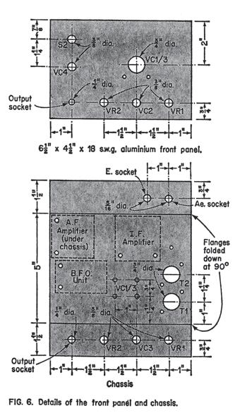
30 30
31 for 6BA (or M3) clearance using a 3.3m.m. diameter twist drill. The two smaller mounting holes for the tuning drive are not drilled at this stage. There are four small holes in the chassis which serve no apparent purpose, and these are merely where insulated leads will eventually pass through the chassis. These should be about 3/16in. diameter and their precise positioning is not critical. It is advisable to fit them with small grommets, but this is not essential. The two mounting holes for VC1/3 are drilled for 4BA clearance using a 4m.m. diameter twist drill. When all the drilling has been completed the two flanges of the chassis are bent down at right angles. Aluminium is fairly soft and pliable, and by using a little ingenuity it should be possible to make these two folds even if no special equipment for this purpose is available. The chassis and panel are, in effect, bolted together by the mounting bushes and nuts of VR1, VR2, VC3, and the output socket. Then the two coilholders are mounted on the chassis, and a soldering is secured under one mounting nut of each bolder (see Figure 7). The tuning capacitor is mounted by two short 4BA bolts which pass through the boles in the chassis and into threaded holes in the underside of the capacitor. It is important that these bolts should no more than fractionally penetrate through the base plate of the capacitor, as if this should be allowed to happen, the mounting screws could damage the fixed vanes of the capacitor. Either the mounting screws must be no more than about 5/16in. long, or washers must be used over them on the underside of the chassis in order to reduce their penetration to an acceptable level. When the tuning capacitor has been mounted, the tuning drive can be placed in position and it can then be used as a template with which the positions of the two smaller mounting holes can be located. The chassis and panel assembly is then dismantled so that these two holes can be drilled to accept 6BA screws. It will also be necessary to carefully enlarge the two 31
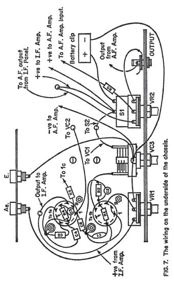
32 mounting holes in the tuning drive so that they will accept 6BA screws. The chassis and panel are then reassembled and the tuning drive is mounted using a couple of ½in. 6BA screws with nuts. The tuning drive is supplied with a short screw which fits into a threaded hole at the rear and towards the top of the drive. This mounting screw is not used here, and is discarded. Before tightening the screw which clamps the output of the drive to the spindle of the tuning capacitor, adjust the drive to read 10 and adjust the tuning capacitor so that its two sets of vanes are fully meshed. The adjustment ranges of the two will then properly coincide. Mixer Wiring Point to point wiring is used in the construction of the mixer, and all this wiring is illustrated in Figure 7. This diagram also shows the other below chassis point to point wiring of the receiver. It is not essential to use point to point wiring when constructing the input circuitry of a S.W. superhet receiver, and plain matrix S.R.B.P. panels, p.c.b.s., etc. can be used. However, it is usually quicker and easier to use point to point wiring, and it has the advantage long connecting wires in parts of the circuit which handle R.F. signals are easily avoided. It should perhaps be pointed out that many component leads are shown as being left quite long in Figure 7 in order to aid the clarity of the diagram. In practice all leads are kept as short and direct as possible. Most of this wiring is quite simple and straightforward. When soldering in C2 and R2 it is probably easier if these two components are connected together before being soldered into position. The same is also true in the case of R4 and C3. The two padder capacitors have rather unusual values, and some difficulty may be experienced in obtaining suitable 32
33 33
34 components. One of the larger mall order component fims could probably supply suitable types, or alternatively these values can be made up by adding two components in parallel. For example, 1100pf can be made up from a 100pf and a l000pf capacitor wired in parallel. Similarly the value of 3000pf can be made up from two 1500pf components. Whether these capacitors are made up from two parallel connected components or single capacitors are used, they must in either case be good quality low tolerance types such as polystyrene or silvered mica capacitors. I.F. Amplifier Wiring The I.F. amplifier, detector, and A.G.C. circuitry is constructed on a plain 0.15in matrix S.R.B.P. panel having 15 x 14 holes. Details of both the component layout and underside wiring of this panel are shown in Figure 8. When a board of the appropriate size has been cut out the two 6BA or M3 clearance mounting holes are drilled out. It it also necessary to enlarge the holes into which the pins and mounting lugs of the two I.F.T.s fit. This can be done using a twist drill of about 2.5m.m. in diameter. I.F.T.l has two tuning cores, one of which can only be adjusted from below. It is therefore necessary to enlarge the appropriate hole in the board so that it is possible to gain access to this core. After the board has been prepared the various components are mounted and their lead out wires are bent flat against the underside of the panel. In the case of the I.F.T.s the mounting Iugs are bent inwards at right angles on the underside of the panel, and this should firmly secure the I.F.T.s. Then the wiring on the underside of the panel is completed. In one or two places the component leads will probably be found to be too short, and it will be necessary to use approx. 22 s.w.g. tinned copper extension wires to bridge the gaps in the wiring. 34
35 35
36 The panel is then used as a template with which the positions of the mounting holes in the chassis are located. The approximate position in which the panel is mounted is shown in Figure 6. Before finally bolting the board in place, wire it up to the rest of the unit. Spacers about 10mm. long are used over the mounting bolts, between the chassis and the board, so that the underside wiring is held clear of the metal chassis. It is a good idea to drill a hole in the chassis beneath I.F.T.1 so that its core can be adjusted from below the chassis. Alternatively, when it comes to carrying out the I.F. alignment the panel can be dismounted, and a temporary earth connection to the board can be made (the normal earth connection is made via a short lead which connects to a soldertag mounted on one of the mounting bolts of the board). Audio Stages The audio amplifier is constructed on a 0.1in. matrix stripboard which has 25 holes by 18 copper strips. Details of this panel appear in Figure 9. Start by cutting out a panel of the correct size and then drill out the two mounting holes. Next make the six breaks in the copper strips and then solder in all the components and link wires, with the I.C. being left until last. The TBA800 I.C. is contained in a sort of 16 pin quad in line package, but where pins 4, 5, 12, and 13 would normally be, the device has a couple of heat tabs instead. Thus the I.C. actually only has 12 pins. Normally the heat tabs would be soldered to an area of copper laminate on a p.c.b., with the copper then acting as a heatsink. However, here the device is used well below its maximum power rating of 5 watts, and so no heatsinking is required. The heat tabs should therefore be bent up out of the way, or even cut off altogether. 36

37 The completed panel is wired up to the rest of the unit before being mounted on the underside of the chassis in the approximate position shown in Figure 6. it is mounted in the same way as the I.F. amplifier panel. 37
38 38
39 B.F.O. Unit This is constructed on a plain 0.15in. matrix panel having 14 by 8 holes, and details of this panel together with details of the other B.F.O. wiring appear in Figure 10. The B.F.O. is built along very similar lines to the I.F. amplifier circuitry. A lead about 150m.m. long carries the B.F.O. output to the I.F. amplifier, but as was stated earlier, no direct connection to the I.F. amplifier is made. A very loose coupling is all that is required, and it is merely necessary to place the B.F.O. output lead near the I.F. amplifier panel. It is advisable to tape this lead in place, rather than just leaving it to hang loose. Apart from anything else, this will provide a more stable B.F.O. signal. Alignment When initially testing the receiver it is best to use the Range 4T coils as this range will almost invariably provide numerous strong signals. The Blue aerial coil plugs into the front coil. holder and the Red oscillator coil plugs into the rear one. With an aerial and a speaker (or headphones) connected to the set, VR1 fully advanced and VR2 well advanced, it should be possible to tune in several stations. For those who are unfamiliar with the Denco coil units it should perhaps be pointed out that as supplied they have their tuning cores virtually fully screwed down for packing purposes. In use the cores are unscrewed so that about 10m.m. of metal screwthread protrudes from the top of each coil. When some stations are received it should be possible to adjust the core of T1 to peak these stations. Alignment of the set starts with the adjustment of the I.F.T. cores. Tune to a fairly weak but consistant station, and then adjust the I.F.T. cores to peak this station. Do not choose a strong station because the A.G.C. action of the receiver will 39
40 make it difficult aurally to detect maximum signal strength. Use a proper trimming tool when adjusting the I.F.T. cores as a wedge shaped tool such as a small screwdriver blade could damage the cores. Tools not specifically designed for trimming applications also tend to have a detuning effect on the I.F.T.s as they are withdrawn from them. A suitable trimming tool for use with the specified I.F.T.s is the Denco type TT5. Adjust the cores of I.F.T.2 first, then the upper core of I.F.T.1, and finally the lower core of I.F.T.1. Repeat this procedure a couple of times to ensure that the cores are all accurately peaked. Note that very little adjustment of these cores should be required as the I.F.T.s are prealigned. It is also worth noting that although I.F.T.1 has a nominal operating frequency of 465kHZ while that of I.F.T.2 is 470kHZ, this difference is so small that in practice the two are perfectly compatible. Next the B.F.O. is aligned, and at the outset this is switched on by operating S2 and then VC4 is set at about half maximum capacitance. Tune the set accurately to a station and then adjust the core of I.F.T.3 until a loud whistle is heard from the speaker or headphones. It should be possible to alter the pitch of this tone by adjusting the core of I.F.T.3, and this is given the setting which gives the lowest possible tone. Adjusting VC4 either side of its central position should produce a rise in the pitch of the whistle. Do not be mislead by any fairly quiet whistling sounds which might be produced as the core of I.F.T.3 is adjusted, these can be caused by harmonics of the B.F.O. being picked up in the aerial circuitry of the set. They are easily distinguished from the main B.F.O. signal being received by the I.F. circuitry, because the latter produces a much stronger signal pick up. Also, the main B.F.O. signal will be present whatever frequency the set is tuned to, whereas harmonics will only be received at certain settings of the tuning control. 40
41 The R.F. alignment is very simple, and it is merely necessary. to tune to a station with VC1/3 at about half maximum capacitance, set VC2 at half capacitance, and then adjust the core of T1 to peak the received signal. This procedure must then be repeated with the other two sets of coils in circuit. It is quite possible that instability will occur at the high frequency end (VC1/3 vanes unmeshed) of one or more of the ranges. Unscrewing the core of T2 might help to eliminate this problem, but remember that if the core of T2 is adjusted it will then be necessary to readjust the core of T1. If this does not completely cure the instability it will be necessary to increase the value of R3 slightly. The correct value is found by means of trial and error, and is the lowest value which will clear the trouble. Do not make this resistor any higher in value than is really necessary, because this will unnecessarily reduce the level of performance obtained at the low frequency end of each band. Using The Set The receiver is quite easy to use, and in fact superhets are more simple to operate than T.R.F. designs. VC1/3 are the ordinary, tuning control, and VR2/S1 are a conventional combined volume and on/off control. VR1 is a sort of R.F. gain control, and it is normally left at maximum (adjusted fully clockwise). It may sometimes happen that an extremely strong A.M. signal will overload the detector and it will then be necessary to turn back VR1 in order to obtain a proper audio output. This will only happen very infrequently though, and only if a very efficient aerial is used. VC2 is the aerial trimmer, and this is always adjusted to peak received signals for maximum signal strength. For the reception of C.W. or S.S.B. signals the B.F.O. is switched in by means of S2. The setting of VC4 is not too important when C.W. signals are being received, but for the reception of S.S.B. it should ideally be offset from its central position. 41
42 For reception of upper sideband, which is used on the 20, 15, and 10 metre amateur bands, the vanes of VC4 should be almost fully meshed. They should be almost fully unmeshed for reception of lower sideband signals. Lower sideband is used on the 160, 80, and 40 metre amateur bands. Strong S.S.B. signals will overload the set by swamping the B.F.O. signal, and this will result in a rather rough and distorted audio output. In extreme cases the audio signal will be virtually unintelligible. In order to resolve strong S.S.B. signals properly it will be necessary to turn back VR1 to a point where no overloading occurs. 42
43 CHAPTER TWO MODULAR SUPERHET In the previous chapter the superhet principle was described, together with very complete details of the circuit operation and construction of a practical receiver. A sort of modular form of construction was used with the circuit being divided up into four main sections (the mixer/oscillator, the I.F. amplifier/detector/a.g.c., the audio amplifier, and the B.F.O.). This modular approach was purposely adopted for two reasons. Firstly it happens to be a very convenient form of construc~ tion, and secondly it leads up to this chapter where a number of different superhet building blocks will be described. The idea here is that the constructor chooses the various building blocks which best suit his or her needs, and then assembles these to produce a complete receiver. This approach is perfectly feasible because superhet receivers tend to naturally break down into such building blocks. Provided one does not stray from standardised parameters (470kHZ I.F.s, usual stage input and output impedances, output levels, etc.), no problems with incompatibility between building blocks will arise. These building blocks have been designed so that they will fit together properly, without any problems of compatibility occuring. Such problems are unlikely to arrise anyway, and, for instance, the audio stages of virtually any superhet receiver could be substituted for those of the receiver described in the previous chapter with perfectly adequate results being obtained. Of course, it would not be a good idea to mix valve and semiconductor circuitry, and all the circuits in the book employ semiconductors rather than valves. If one wants the ultimate in performance from the early stages of the set it is possible 43
44 to make a good case in favour of using valves in these stages, with a beam deflection valve being used in the mixer stage. However, most people prefer the convenience of semiconductors, which are easier to use and more readily available than special types of valve. It is probably true to say that there is not a great deal of difference between the performance obtained from the best valve and semiconductor devices anyway. Image Rejection The problem of image rejection was raised in the previous chapter, and it was pointed out that the basic superhet receiver which was described there had only a limited amount of image rejection at high frequencies. In more sophisticated receivers it is normal to take steps to increase the level of image rejection, and before going on to consider some practical circuits the methods of increasing image rejection will be discussed. There are two basic ways of improving image rejection, either add more tuned circuits ahead of the mixer, or use a higher I.F. in previous eras the former was the method most often used in good quality communications receivers. These often had two R.F. stages with a tuned circuit at the input to each one, plus a tuned circuit at the input to the mixer. This provides some three tuned circuits ahead of the mixer, and this gives a level of R.F. selectivity which provides excellent image rejection. Unfortunately there are drawbacks to this arrangement, one of which is the generous R.F. screening which is required in order to prevent instability. Another is that including the oscillator tuned circuit there are no less than four tuned circuits which must be maintained in good alignment if good results are to be procured from this arrangement Another problem, and perhaps the most major one, is that of cross-modulation which is a form of intermodulation. This 44
45 distortion inevitably results in any amplifier since a perfectly linear amplifier has yet to be invented. This distortion can result in the modulation of one signal in the receivers R.F. passband being heard on the main signal which is being received, even though the two stations are well separated. It is from this that the term cross moduiatlon is derived. In a practical situation the results of cross modulation are never likely to be heard in this way, since the R.F. passband of a receiver is quite wide and the R.F. and mixer stages are likely to be handling dozens or even hundreds of stations. Cross modulation is much more likely to manifest itself in the form of a general increase in the background noise level. This is due to the fact that most S.W. signals consist of a complex and changing range of frequency components, and as the components of each signal react with the components of all the other signals in the receiver s R.F. passband, a vast range of new signals are produced. Those that are converted by the mixer to frequencies which lie within the sets I.F. passband are heard as a jumble of noise at the output. The reason that cross modulation is such an important factor is simply that no matter how sensitive and selective the I.F. stages of a set are made, it will not be possible to copy weak signals if they are drowned in noise resulting from cross modulation. One might think that the old system of having three tuned circuits ahead of the mixer would give a good cross modulation performance by reducing the R.F. passband, and therefore reducing the number of signals handled by the input stages of the receiver. In practice this is not the way things work out, because the R.F. bandwidth of the set will still be fairly wide even if three tuned circuits are used, and in order to eliminate problems with cross modulation noise in this way it is necessary to have an R.F. bandwidth which is nearly as narrow as the I.F. bandwidth. This is not really a practical proposition in a receiver which is to cover more than a single frequency! 45
46 Having two R.F. stages actively encourages cross modulation because there is inevitably a degree of distortion in each of these amplifiers. Furthermore, the effect of these stages is to increase the signal levels encountered in the input stages of the set, which results in higher levels of distortion. This is particularly so by the time signals reach the mixer, as any really strong signals will have been boosted to a level which will drive the mixer outside its linear operating range. Severe cross modulation will then occur, making it impossible to copy weak stations. The modem approach to minimising the problem of cross modulation is to use no R.F. stage, and a high frequency I.F. The two I.F.s most often used are 5.5MHZ and 9MHZ. These produce an image signal which is 11MHZ and 18MHZ respectively away from the main response. Even a single tuned circuit ahead of the mixer will then provide good image rejection right up to the higher frequency limit of the S.W frequency spectrum. However, neither home constructed or commercially produced receivers of this type are frequently encountered in amateur circles. This is due to difficulties which exist with this arrangement, the most major one being that of obtaining good selectivity. I.F. transformers incorporate ordinary L - C tuned circuits, and at frequencies in the region of 5.5 to 9MHZ L - C circuits simply would not produce the high degree of selectivity that a good communications receiver must possess. In order to obtain the required level of selectivity from a high I.F. it is necessary to use a crystal filter, and these tend to be rather expensive if purchased ready made. A good crystal filter can cost more than the remainder of the parts for a receiver! It is possible to construct ones own filter, but obtaining suitable parts is likely to be something of a problem. Aligning the completed unit can also cause problems. An alternative to using a crystal I.F. filter is to use the double conversion approach. Here the output from the first I.F. amplifier is fed to a second mixer where the signal is heter- 46
47 odyned to a conventional 470kHZ I.F. Thus the high first I.F. provides good image rejection while the low second I.F. provides good selectivity. This method is probably more common than the single conversion high I.F. one, but neither are as popular as the single conversion low I.F. type of receiver. This is the type of set that we will be concerned with in this chapter. A design of this type has to be something of a compromise, but this is not to say that a very high level of performance cannot be attained. The building blocks which are described in the following pages can be assembled to produce an excellent S.W. set. Whichever of the front ends the constructor chooses (there are four alternatives) there will be two tuned circuits ahead of the mixer. The coils used in the front end circuits are modem ferrite cored types which have quite high Q values. They therefore provide a fairly narrow R.F. passband, and thus also a quite high degree of image rejection even at frequencies in the 20 to 30MHZ region. Three of the front ends which are described are active units, and can provide a fairly high level of gain (20dB or more at most frequencies). All incorporate R.F. gain controls though, and the gain can be reduced to less than unity so that overloading of the mixer can be avoided. The remaining front end circuit is a passive type, and it does not therefore introduce any cross modulation directly, or by increasing the signal amplitude fed to the mixer. When using any S.W. superhet it is worth bearing in mind that obtaining the best possible aerial signal and using maximum R.F. gain does not necessarily provide the best results. For examples, some time ago the author bad a quite conventional valved communications receiver which invariably failed to produce any stations at all on the 40 metre amateur band after dark. This band is noted for poor reception after dark due to its very close proximity to the 41 metre broadcast band, with many broadcast stations encroaching into the amateur band 47
48 allocation. The very strong broadcast stations tend to cause severe cross modulation which obscures the comparatively weak amateur stations. The rather unlikely cure to the problem was to disconnect the aerial and then place the aerial plug close to its socket. This provided only a very loose coupling between the aerial and the receiver, but with the A.F. gain well advanced it was still possible to copy many stations, including some amateur ones. In fact, stations as far away as South America were copied. What was happening here is quite simple; although the strengths at which stations were received was being greatly diminished, the cross modulation was being reduced by an even greater amount. Therefore, stations that were originally drowned in the cross modulation noise were brought above this noise level by attenuating the aerial signal. This feature is something that should be kept in mind when using any S.W. superhet receiver. Details of the various building blocks will now be given. Constructional information will not be provided since it is assumed that anyone undertaking construction of these circuits will have reached the stage where they can build practical units from a circuit diagram. The following chapter will describe some additional circuitry which can be used in conjunction with certain of these building blocks to provide a double conversion receiver. The final chapter will deal with add on circuits such as an S Meter, A Multiplier, etc. R.F. Amplifiers The circuit diagram of an R.F. amplifier which employs a bipolar transistor as its active element is shown in Figure 11. Operation of the circuit is quite simple with Tr1 being used is the common emitter amplifying mode. The potential divider formed by R1 and R2 provides the base bias voltage for Tr1, while R3 and VR1 form the emitter bias resistance. C3 is the 48
49 usual emitter bypass capacitor. VR1 enables the operating current of the stage to be varied, and hence it also controls the gain of the stage. Gain is at maximum with VR1 set for minimum resistance. R3 is a current limiting resistor. 49
50 The base of Tr1 is fed from the low impedance coupling winding on T1. via D.C. blocking capacitor C2. VC1 is the tuning capacitor for the R.F. stage. The output of the R.F. amplifier is coupled to the mixer stage by way of R.F. transformer T2. VC3 is the tuning capacitor for the mixer tuned circuit and VC2 is a panel trimmer control which enables this tuned circuit to be kept in proper alignment. It is not recommended that VC1 should be ganged with VC3 (which is ganged with the oscillator tuning capacitor of course) because this makeslt necessary to have the R.F. amplifier circuitry and the mixer/oscillator circuitry in close proximity to one another. If this is done it becomes absolutely essential to screen off the R.F. amplifier circuitry in order to obtain good stability. This is not as easy to accomplish as one might imagine. In the authors opinion it is far better to have VC1 as a separate component with the R.F. circuitry physically well spaced from the mixer/oscillator circuitry. Screening then becomes unnecessary. Note that T2, VC2, and VC3 are only shown here to illustrate how the R.F. amplifier is connected to the mixer. These are actually part of the mixer circuit, and are positioned close to the rest of the mixer circuitry. These last two points are also relevant to the next two front end circuits which are described. T1 is a Denco Blue aerial coil for transistor useage, and T2 is a Yellow R.P. coil for transistor useage. The following front end circuits all employ the same two coil typed. Jugfet Amplifier The circuit diagram of an R.F. amplifier using a Jugfet (junction gate field effect transistor) is shown in Figure 12. This has a similar performance to the bipolar R.F. amplifier circuit, but it provides a slightly lower noise level and has a better cross modulation performance. 50
51 The gate terminal of Tr1 is bias by being tied to earth through the tuned winding of T1. There is no need to use the low impedance coupling winding of T1 in this circuit since f.e.t.s have extremely high input impedances, and, the tuned circuit can therefore be coupled direct to the gate of Tr1. 51
52 R1 and VR1 form the source bias resistance for Tr1, and C2 is the source bypass capacitor. VR1 enables the standing current through the stage to be varied, and it thus controls the gain of VR1. As was the case with the previous circuit, gain is at a maximum with VR1 adjusted for minimum resistance. R2 and C1 are a supply decoupling network. MOSFET Amplifier MOSFETs (Metal Oxide Semiconductor Field Effect Transistons) are somewhat more expensive than most other types of transistor, but this additional expense is easily justified by their superior performance when compared with bipolar and Jugfet devices in R.F. applications. The circuit diagram of a MOSFET R.F. amplifier is shown in Figure 13. This provides a slightly higher level of gain than the previous two designs, and it has a lower noise level. Perhaps more importantly, it has a much better cross modulation performance, and MOSFETs are able to handle quite high signal amplitudes without producing high levels of distortion. As was the case with the Jugfet R.F. amplifier, the high input impedance of the transistor enables the aerial tuned circuit to be directly coupled to the input gate. Tr1 is a dual gate MOSFET, and the input signal is coupled to the g1 terminal. The voltage gain at this terminal is determined by the g2 potential of the device, and VR1 can be used to vary this voltage from zero to about 2 volts. The gain of Tr1 is at a minimum when the gate 2 voltage is zero, and at maximum when it is at a level of about 2 volts. VR1 thus acts as the R.F. gain control. C1 filters out any stray R.F. signals which might otherwise be picked up at the g2 terminal, and result in instability or loss of performance. It also minimises any noise spikes which are produced at VR1 slider as this control is adjusted. 52
53 R2 and (2 are the source bias resistor and bypass capacitor respectively, and R3 and C3 are a supply decoupling network. MOSFETs have a reputation of being easily damaged by static charges due to their extremely high input impedances (which 53
54 are usually something in the region of 1,000,000 Meg. ohms). The transistor has integral protective diodes, and it is not therefore easily damaged in this way. It needs no more handling precautions than any normal semiconductor device. Bandpass input It is quite possible to use more than one tuned circuit before the mixer without using any amplifying stages in this part of the circuit. Such an arrangement is usually termed a bandpass circuit, and the circuit diagram of such an arrangement appears in Figure 14. Here the two R.F. transformers are merely coupled together by way of two low impedance windings. Of course, such an arrangement does not provide any gain, just the opposite in fact, and there is a significant loss through the input filter. However, this circuit produces no cross modulation of its own, and quite good results can be obtained using this arrangement. 54
55 Mixer/Osc. Stages The mixer circuit which was used in the receiver which was described in the first chapter is simple and inexpensive, but as far as cross modulation performance is concerned it leaves a lot to be desired. As was stated in Chapter 1, the gain of the mixer transistor varies with changes in operating current. As the oscillator signal swings positive and negative the operating current decreases and increases, and as it does so it therefore modulates the input signal and the desired mixing action is produced. The problem with this system is that the aerial signal also causes the operating current of the transistor to vary in precisely the same way as the oscillator signal does. This results in changes in the gain of the transistor which obviously causes distortion, including intermodulation distortion (of which cross modulation is a type). There is no simple way of eliminating this distortion, but even if there was there would be no point in doing so since if the distortion is removed, so is the mixing action. This type of mixer thus has an inherently high cross modulation level. Dual gate MOSFETs make excellent R.F. amplifiers because, as was pointed out previously, they can handle high signal levels while producing only low distortion levels. It was also explained that the gain of the device was controlled by the voltage at the g2 terminal. Dual gate MOSFETs make excellent mixers, as by coupling the aerial signal to the g1 terminal and the oscillator signal to the g2 terminal, the oscillator will vary the gain of the device and thus modulate the aerial signal. A good mixing action is produced in this way. Only low levels of cross modulation are generated by a dual gate MOSFET mixer because the gain of the device does not vary greatly with variations in the aerial signal amplitude, only with. changes in the oscillator signal level. 55
56 56
57 Since dual gate MOSFETs provide the basis of by far the best of simple mixer circuits, only this type of mixer will be considered here, there being little point in providing details of more complex designs of vastly inferior performance. The circuit diagram of a simple MOSFET mixer is shown in Figure 15, and this also shows the circuit of the recommended oscillator circuit. The mixer tuned circuit is fed direct into the g1 terminal of Tr1, and the tuned winding on the mixer transformer (T2) provides the uecessaiy D.C. path to earth for Tr1 g1. R1 and R2 form a simple potential divider which bias Tr1 g2 about 1 volt positive. The oscillator signal is coupled to the g2 terminal by way of C2, and by modulating the bias voltage this signal varies the gain of Tr1. R4 and C3 are the source bias resistance and bypass capacitor. The output of the mixer Is taken from Tr1 drain, which connects to the first I.F. transformer of the I.F. amplifier. R3 and C1 are a supply decoupling network. The oscillator circuit may look a little familiar, and this is because it is basically the same circuit that was used in the mixcr/oxcillator stages of the receiver which was described in Chapter 1. As this stage is not coupled to the mixer transformer this time, the base bias network (R7 and R8) and earth return capacitor (C8) are connected direct to Tr2 base. When used as a combined mixer/oscillator circuit it is necessary to select the circuit values to limit the amplitude of the oscillations, as otherwise instability is almost certain to occur. This is less of a problem when the circuit is used only as an oscillator, and the opposite was in fact found to be the case, with it being necessary to reduce the value of the emitter-base resistor in order to increase the amplitude of the output signal to an acceptable level. It is not quite as simple to construct this mixen/osc. circuit using a point to point wining system as it was in the case of the mixen/osc. circuitry of the receiver described in chapter 1, 57
58 because more component anchor points are required here, and there are only the same number of spare coilholder pins which can be used. Note that where some coil windings are unused, no connections should be made to the relevant pins of the coilholder. Thus, for example, no connections should be made to pins S and 7 of the coilholder for T2 (Figures 12 and 13). It is possible to solder some parts of the circuit together without using any anchor points, and so overcome this problem, but this is likely to give a rather flimsy assembly. This can result in stability of the oscillator frequency being affected by vibration, and it is not likely to provide adequate reliability. The method preferred by the author is to use point to point wiring with miniature tagstrips being mounted near the coilholders. The purpose of these tagstnips is to provide additional anchor points. Alternative Oscillator The oscillator circuit shown in Figure 15 is probably more stable (with regard to variations in frequency) than most people realise. It is unlikely that stability could be greatly increased without resorting to highly sophisticated circuitry, and this is really a complete subject in itself. Such things as frequency synthesisers are certainly beyond the scope of this book, and few constructors bother to go to such lengths anyway. One simple way of improving the stability of the circuit of Figure 15 is to connect a 7.5 volt zener diode in parallel with C1 (cathode to the negative supply). This will substantially reduce any variations in the output frequency due to changes in the supply voltage (due to battery ageing etc.). This modification will similarly aid the stability of the alternative oscillator circuit which appears in Figure 16. This employs a Jugfet in a simple common source inductive feedback oscillator. Only two of the windings on the oscillator 58
59 transformer are used in this circuit. When the range 3 and 4 coils are in circuit the tuned winding of the coil does not provide a D.C. path to earth for Tr2 gate due to the presence of the padder capacitors (C5 and C6). R5 has therefore been included to provide this D.C. path. The value of this resistor is more critical than one might think, and if it is made too low in value its shunting effect on the tuned circuit reduces the amplitude of the output signal, or oscillation ceases all together. On the other hand, if it is made too high in value it 59
60 is not able to drain away the negative charge which builds up on Tr2 gate. As a result, this charge takes Tr2 gate about a volt or so negative of the earth rail, and oscillation is then halted as the transistor is cut off. This circuit would appear to be slightly more stable than the one of Figure 15, but it does have a slight disadvantage. This is that it is difficult to obtain a sufficiently high signal amplitude from the circuit. The signal level of Tr2 drain (the obvious signal take off point) is far too low, and it is necessary to take the output from the tuned circuit instead. On ranges 3 and 4 the circuit has a performance which is very much the same as that of the circuit of Figure 15 with regard to sensitivity, but on range 5 results would appear to be slightly inferior. The reason for this is probably that on range 5 the oscillator operates on the second harmonic and not on the fundamental. In other words the oscillator is actually operating at half the required frequency, and it is the second harmonic signal (which is at double the frequency of the fundamental) which is used as the oscillator signal. Because the f.e.t. circuit oscillates less violently than the bipolar one, It does not provide as much harmonic output, although the amplitudes of the fundamentals are very much the same. I.F. Amplifier If a simple I.F. amplifier is all that is required, the one described in Chapter 1 can be used. It is, however, more normal to use a two stage I.F. amplifier, and the circuit diagram of one of these appears in Figure 17. The fact that this circuit uses two transistors does not mean that it has something like one hundred times the gain (the gain that can be attained by a single 470kHZ I.F. amplifier) of the single transistor circuit described earlier. Even when using a very carefully and well planned layout, the gain that can be obtained is limited by stay feedback over the circuit. If the gain 60
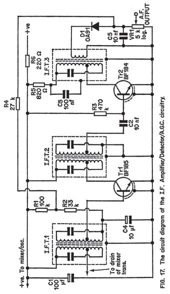
61 61
The G4EGQ RAE COURSE Lesson 9 Transmitters Lesson 8 looked at a simple transmitter exciter comprising of oscillator, buffer and multiplier stages.
 Lesson 8 looked at a simple transmitter exciter comprising of oscillator, buffer and multiplier stages. The power amplifier The output from the exciter is usually very low and it is necessary to amplify
Amateur Radio Examination EXAMINATION PAPER No. 275 MARKER S COPY
 01-6-(d) An Amateur Station is quoted in the regulations as a station: a for training new radio operators b using amateur equipment for commercial purposes c for public emergency purposes d in the Amateur
The Walford Electronics Ford Receiver Kit Project Construction Manual
 The Walford Electronics Ford Receiver Kit Project Construction Manual Walford Electronics Ford Receiver construction manual V1.5 Page 1 of 22 Introduction The Ford receiver has four stages: The first stage
Module 8 Theory. dbs AM Detector Ring Modulator Receiver Chain. Functional Blocks Parameters. IRTS Region 4
 Module 8 Theory dbs AM Detector Ring Modulator Receiver Chain Functional Blocks Parameters Decibel (db) The term db or decibel is a relative unit of measurement used frequently in electronic communications
Radio Receivers. Al Penney VO1NO
 Radio Receivers Al Penney VO1NO Role of the Receiver The Antenna must capture the radio wave. The desired frequency must be selected from all the EM waves captured by the antenna. The selected signal is
HT-1A Dual Band CW QRP Transceiver. Kit Building Instructions
 HT-A Dual Band CW QRP Transceiver Kit Building Instructions Rev B, July 8, 08 Designed by BD4RG Exclusively distributed by CRKITS.COM and its worldwide distributors Join the group http://groups.io/g/crkits
THE 1956 ZENITH ROYAL 500 TRANSISTOR OWL S EYES RADIO.
 THE 1956 ZENITH ROYAL 500 TRANSISTOR OWL S EYES RADIO. Dr. H. Holden. Feb. 2018. Introduction: The Zenith Royal 500 radio appeared in 1956, two years later than the Regency TR1 which was the first commercial
The ROSE 80 CW Transceiver (Part 1 of 3)
") Build a 5 watt, 80 meter QRP CW Transceiver!!! Page 1 of 10 The ROSE 80 CW Transceiver (Part 1 of 3) Build a 5 watt, 80 meter QRP CW Transceiver!!! (Designed by N1HFX) A great deal of interest has been
Build a 5 watt, 80 meter QRP CW Transceiver!!! Page 1 of 10 The ROSE 80 CW Transceiver (Part 1 of 3) Build a 5 watt, 80 meter QRP CW Transceiver!!! (Designed by N1HFX) A great deal of interest has been
Solid State Short Wave Receivers For Beginners R. A. PENFOLD
 Solid State Short Wave Receivers For Beginners R. A. PENFOLD 1 SOLID STATE SHORT WAVE RECEIVERS FOR BEGINNERS SOLID STATE SHORT WAVE RECEIVERS FOR BEGINNERS by R. A. PENFOLD BERNARDS (publishersl LTD The
G6ALU 20W FET PA Construction Information
 G6ALU 20W FET PA Construction Information The requirement This amplifier was designed specifically to complement the Pic-A-Star transceiver developed by Peter Rhodes G3XJP. From the band pass filter an
 file:///c /BoatAnchors/Hammarlund/HQ170A/HQ170SVC.TXT Dear OM: This form is being prepared to provide prompt attention to a complaint as a result of trouble that may be experienced in the field. In addition
Radio Receivers. Al Penney VO1NO
 Radio Receivers Role of the Receiver The Antenna must capture the radio wave. The desired frequency must be selected from all the EM waves captured by the antenna. The selected signal is usually very weak
A 75-Watt Transmitter for 3 Bands Simplified Shielding and Filtering for TVI BY DONALD H. MIX, W1TS ARRL Handbook 1953 and QST, October 1951
 A 75-Watt Transmitter for 3 Bands Simplified Shielding and Filtering for TVI BY DONALD H. MIX, W1TS ARRL Handbook 1953 and QST, October 1951 The transmitter shown in the photographs is a 3-stage 75-watt
50 (FET) Field Effect Transistor Projects F. G. RAYER, T. ENG. (CEI), ASSOC. IERE
 Field Effect Transistor Projects F. G. RAYER, T. ENG. (CEI), ASSOC. IERE") 50 (FET) Field Effect Transistor Projects F. G. RAYER, T. ENG. (CEI), ASSOC. IERE 50 (F.E.T.) Field Effect Transistor Projects by F. G. RAYER, T. Eng. (CEI), Assoc. IERE BABANI PRESS The Publishing Division
50 (FET) Field Effect Transistor Projects F. G. RAYER, T. ENG. (CEI), ASSOC. IERE 50 (F.E.T.) Field Effect Transistor Projects by F. G. RAYER, T. Eng. (CEI), Assoc. IERE BABANI PRESS The Publishing Division
1 TRANSISTOR CIRCUITS
 FM TRANSMITTERS The first group of circuits we will discuss are FM TRANSMITTERS. They can be called SPY TRANSMITTERS, FM BUGS, or a number of other interesting names. They all do the same thing. They transmit
A 100-Watt Transmitter Using a Pair of VT1625s
 12/16/2007 6:00 PM VT1625 100 Watt Transmitter A 100-Watt Transmitter Using a Pair of VT1625s FIG. 10.6 A 100-watt transmitter for five bands, using salvaged TV power transformer and surplus 1625 amplifier
KACHINA 1 SSB TRANSCEIVER
 KACHINA 1 SSB TRANSCEIVER THEORY OF OPERATION The Kachina 1 Amateur Band Transceiver is a highly sophisticated, state of the art, piece of communication equipment, housed in the smallest of packages. Yet,
HF Receivers, Part 2
 HF Receivers, Part 2 Superhet building blocks: AM, SSB/CW, FM receivers Adam Farson VA7OJ View an excellent tutorial on receivers NSARC HF Operators HF Receivers 2 1 The RF Amplifier (Preamp)! Typical
HF Amateur SSB Receiver
 HF Amateur SSB Receiver PCB Set for radio club project http://rhelectronics.net PCB for DIY HF Amateur SSB Receiver 20M The receiver is a simple syperheterodyne type with quartz crystal filter. The circuit
Treetop Circuits Owner s Manual for SB-SB-600 Adapter Version 1
 The SB-600 SSB adapter from Treetop Circuits (Fig. 1) is designed specifically as an accessory to the Hammarlund SP-600 series of receivers. It provides enhanced performance on SSB and CW signals, using
ZN414Z, ZN415E, ZN416E AM RADIO RECEIVERS
 GEC PLESSEY [SEMICONDUCTORS ZN414Z, ZN415E, ZN416E AM RADIO RECEIVERS FEATURES Single cell operation (1.1 to 1.6 volt, operating range) Low current consumption 150kHz to 3MHz frequency range (i.e. full
FM RADIO KIT ESSENTIAL INFORMATION. Version 2.0 GET IN TUNE WITH THIS
 ESSENTIAL INFORMATION BUILD INSTRUCTIONS CHECKING YOUR PCB & FAULT-FINDING MECHANICAL DETAILS HOW THE KIT WORKS GET IN TUNE WITH THIS FM RADIO KIT Version 2.0 Build Instructions Before you start, take
Amateur Radio Examination EXAMINATION PAPER No. 260 MARKER S COPY
 01-7-(a) An authorised officer from the Ministry of Business, Innovation & Employment can inspect a General Amateur Operator's Certificate of Competency: a at any time b during business hours c at any
Balanced Line Driver & Receiver
 Balanced Line Driver & Receiver Rod Elliott (ESP) Introduction Sometimes, you just can't get rid of that %$#*& hum, no matter what you do. Especially with long interconnects (such as to a powered sub-woofer),
RadiØKit Μ CW HAM RADIO TRANSCEIVER KIT. Assembly and operating manual
 RadiØKit-120 20Μ CW HAM RADIO TRANSCEIVER KIT Assembly and operating manual Boreiou Ipirou 78 Kolonos Athens- Greece - 10444 Tel: 210.5150527 210.5132673 www.freebytes.com Thank you for buying RadiØKit-1,
GRID DIP METER DESIGN
 GRID DIP METER DESIGN BY G0CWA MAY 2013 This, my next offering of test equipment is an exceptionally useful item of test equipment with many uses, some are listed below. To coin a phrase given to me by
S-Pixie QRP Kit. Student Manual. Revision V 1-0
 S-Pixie QRP Kit Student Manual Revision V 1-0 Introduction The Pixie 2 is a small, versatile radio transceiver that is very popular with QRP (low power) amateur radio operators the world over. It reflects
RADIO RECEIVERS ECE 3103 WIRELESS COMMUNICATION SYSTEMS
 RADIO RECEIVERS ECE 3103 WIRELESS COMMUNICATION SYSTEMS FUNCTIONS OF A RADIO RECEIVER The main functions of a radio receiver are: 1. To intercept the RF signal by using the receiver antenna 2. Select the
KWM-2/2A Transceiver THE COLLINS KWM-2/2A TRANSCEIVER
 KWM-2/2A Transceiver Click the photo to see a larger photo Click "Back" button on browser to return Courtesy of Norm - WA3KEY THE COLLINS KWM-2/2A TRANSCEIVER Unmatched for versatility, dependability and
Topic Advanced Radio Receivers. Explain that an RF amplifier can be used to improve sensitivity;
 Learning Objectives: At the end of this topic you will be able to; Explain that an RF amplifier can be used to improve sensitivity; Explain that a superheterodyne receiver offers improved selectivity and
N3ZI Kits General Coverage Receiver, Assembly & Operations Manual (For Jun 2011 PCB ) Version 3.33, Jan 2012
 Version 3.33, Jan 2012") N3ZI Kits General Coverage Receiver, Assembly & Operations Manual (For Jun 2011 PCB ) Version 3.33, Jan 2012 Thank you for purchasing my general coverage receiver kit. You can use the photo above as a
N3ZI Kits General Coverage Receiver, Assembly & Operations Manual (For Jun 2011 PCB ) Version 3.33, Jan 2012 Thank you for purchasing my general coverage receiver kit. You can use the photo above as a
Building the Sawdust Regenerative Receiver
 Building the Sawdust Regenerative Receiver Introduction The Sawdust is a super regenerative receiver using the basic Armstrong design architecture. The receiver uses one toroidal transformer to provide
D-STATE RADIOMETER. I. Switch Driver
 NATIONAL RADIO ASTRONOMY OBSERVATORY Green Bank, West Virginia Electronics Division Internal Report No. 13 A SOLID-STATE RADIOMETER James L. Dolan August 1963 Rerun 11/10/ 66: 50 D-STATE RADIOMETER Work
Transmitters and receivers
 Chapter 3 Transmitters and receivers Transmitters and receivers are used extensively in aircraft communication and navigation systems. In conjunction with one ore more antennas, they are responsible for
SPECIFICATIONS: Subcarrier Frequency 5.5MHz adjustable, FM Modulated +/- 50KHz. 2nd 11MHz >40dB down from 5.5MHz
 Mini-kits AUDIO / SUBCARRIER KIT EME75 Version4 SPECIFICATIONS: Subcarrier Frequency 5.5MHz adjustable, FM Modulated +/- 50KHz Subcarrier Output 1.5v p-p Output @ 5.5MHz DESCRIPTION & FEATURES: The Notes
2-Tone Generator For 145Mhz
 Wolfgang Schneider, DJ8ES 2-Tone Generator For 145Mhz An RF amplifier stage is not only classified by amplification, which is as high as possible, and thus by its maximum output. What is frequently not
Take another look at the Noise Bridge:
 Take another look at the Noise Bridge: Author K.P.Barnsdale ZL3KB Date 21 October 1998 Diagrams: 1. Circuit diagram. 2. PCB layout 3. Front panel layout 4. Internal layout diagram 5. Inductance chart Introduction
A GOOD REGENERATIVE RECEIVER WITH SIMPLE FINE TUNING (2008)
") A GOOD REGENERATIVE RECEIVER WITH SIMPLE FINE TUNING (2008) A good SSB-CW-AM regenerative receiver with a fine tuning by moving the wooden stick with a grounded piece of PCB towards the coil. A good regenerative
A GOOD REGENERATIVE RECEIVER WITH SIMPLE FINE TUNING (2008) A good SSB-CW-AM regenerative receiver with a fine tuning by moving the wooden stick with a grounded piece of PCB towards the coil. A good regenerative
THE AMAZING BARLOW WADLEY XCR-30 CRYSTAL CONTROLLED 30 BAND TRANSISTOR RADIO. (A method to set the AGC) H. Holden, 2018.
 H. Holden, 2018.") THE AMAZING BARLOW WADLEY XCR-30 CRYSTAL CONTROLLED 30 BAND TRANSISTOR RADIO. (A method to set the AGC) H. Holden, 2018. Introduction: The Barlow Wadley XCR-30 radio is well known to amateur radio enthusiasts
THE AMAZING BARLOW WADLEY XCR-30 CRYSTAL CONTROLLED 30 BAND TRANSISTOR RADIO. (A method to set the AGC) H. Holden, 2018. Introduction: The Barlow Wadley XCR-30 radio is well known to amateur radio enthusiasts
Assembly Instructions for the 1.5 Watt Amplifier Kit
 Assembly Instructions for the 1.5 Watt Amplifier Kit 1.) All of the small parts are attached to a sheet of paper indicating both their value and id. 2.) Leave the parts affixed to the paper until you are
ssb transceiver single-band using the LM373 communications IC
 single-band ssb transceiver using the LM373 communications IC How to use the versatile LM373 and several other ICs to build a compact ssb transceiver for 14 MHz About two years ago a new products announcement
The KW 76A MOBILE RECEIVER
 The KW 76A MOBILE RECEIVER The KW 76A Receiver is designed primarily for mobile operation. The compact layout makes it particularly suitable for under dash mounting in a vehicle. When used at a Home station
Wimborne Publishing, reproduce for personal use only
 In part 1 we looked at some of the principles involved with measuring magnetic fields. This time, we take a more practical approach and look at some experimental circuits. The circuits illustrated are
Building the Sawdust Regenerative Receiver
 Building the Sawdust Regenerative Receiver Introduction The Sawdust is a super regenerative receiver using the basic Armstrong design architecture. The receiver uses one toroidal transformer to provide
MISCELLANEOUS. Figure 1.
 Reading 41 Ron Bertrand VK2DQ http://www.radioelectronicschool.com MISCELLANEOUS The purpose of this reading is to catch anything that may have slipped through the previous forty readings or just does
TBA120 Series & SN FM Demodulator IC
 TBA120 Series & SN76660 - FM Demodulator IC The TBA120 Series ICs provide a high-gain limiting IF amplifier and a quadrature coincidence detector in one package. These ICs are primarily intended for extraction
No.01 Transistor Tester
 Blocks used Tester Circuits No.01 Transistor Tester Electronic components may break down if used or connected improperly. Let s start with a simple tester circuit project designed to teach you how to handle
30 Watt Audio Power Amplifier
 30 Watt Audio Power Amplifier Including Preamp, Tone Controls, Reg dc Power Supply, 18 Watt into 8 Ohm - 30W into 4 Ohm loads Amplifier Section Circuit diagram: Audio Power Amplifier Circuit Diagram This
INDUCTION BALANCE Murray/Modern Magazines, reproduce for personal use only METAL DETECTOR
 Project 549 INDUCTION BALANCE Murray/Modern Magazines, reproduce for personal use only METAL DETECTOR A really sensitive design operating on a different principle from that of other published circuits.
The 144MHz Anglian 3 transverter
 The 144MHz Anglian 3 transverter A high performance 144/28MHz transverter G4DDK document issue 1 12/9/16 Introduction Anglian 3 is an update to the 144MHz Anglian 2 transverter. The Anglian 2 is no longer
Homebrew and Experimenters Group HF Inductance Bridge (Compiled by VK2TOX)
") Homebrew and Experimenters Group HF Inductance Bridge (Compiled by VK2TOX) There are a number of ways to measure inductances used in construction of RF equipment. One of the most versatile ways is with
Homebrew and Experimenters Group HF Inductance Bridge (Compiled by VK2TOX) There are a number of ways to measure inductances used in construction of RF equipment. One of the most versatile ways is with
Step by Step Building PJ meter ARDF Receiver Kit. CRKITS.COM August 5, 2013
 Step by Step Building PJ-80 80-meter ARDF Receiver Kit CRKITS.COM August 5, 2013 What is ARDF? ARDF is the abbreviation of Amateur Radio Direction Finding, or so called Fox Hunting. If you are looking
Operational Amplifiers
 Operational Amplifiers Table of contents 1. Design 1.1. The Differential Amplifier 1.2. Level Shifter 1.3. Power Amplifier 2. Characteristics 3. The Opamp without NFB 4. Linear Amplifiers 4.1. The Non-Inverting
KN-Q10 Assembly Manual
 KN-Q10 Assembly Manual Translated by Adam Rong, BD6CR/4 with permission from Ke Shi, BA6BF Edited by Stephen, VK2RH Revision B, Oct 14, 2010 Thank you for purchasing the KN-Q10 4 Band SSB/CW Dual Mode
C.M.HOWES COMMUNICATIONS CTU150 Instructions
 CTU150 Instructions The HOWES CTU150 is an antenna matching unit for use with shortwave transmitters and receivers. A novel constructional method is used - all parts being mounted on a Printed Circuit
51J-4 COMMUNICATIONS RECEIVER
 51J-4 COMMUNICATIONS RECEIVER Transcribed from 520-5014-00 August 15, 1954 GENERAL DESCRIPTION The Collins 51J-4 Receiver is designed for communication applications where stability and dial accuracy of
REPAIRING THE RM KL400 LINEAR AMPLIFIER.
 REPAIRING THE RM KL400 LINEAR AMPLIFIER. Les Carpenter G4CNH December 2012 Page 1 of 20 The following is a step by step guide to fixing your KL400 amplifier. Each part will be individually tested up to
THE INTERMEDIATE VFO
 THE INTERMEDIATE VFO Some Intermediate tutors have reported difficulties in either obtaining parts for the RSGB Intermediate textbook VFO or in getting the VFO going once they have the parts. This alternative
Hear SSB amateurs on your shortwave receiver
 Hear SSB amateurs on your shortwave receiver Peter Parker VK3YE Since most amateurs switched from AM to single sideband more than 40 years ago, it hasn't been possible to receive them with an unaided shortwave
Chapter 3. Question Mar No
 Chapter 3 Sr Question Mar No k. 1 Write any two drawbacks of TRF radio receiver 1. Instability due to oscillatory nature of RF amplifier.. Variation in bandwidth over tuning range. 3. Insufficient selectivity
Cricket 80a Assembly Manual v Copyright David Cripe NM0S The 4 State QRP Group
 Cricket 80a Assembly Manual v. 1.0 Copyright 2017 David Cripe NM0S The 4 State QRP Group Introduction Thank you for purchasing a CRICKET 80a Transceiver. We hope you will enjoy building it and find it
WA3RNC 30 METER CRYSTALPLEXER TRANSMITTER KIT ASSEMBLY INSTRUCTIONS
 WA3RNC 30 METER CRYSTALPLEXER TRANSMITTER KIT ASSEMBLY INSTRUCTIONS Description The WA3RNC 30 Meter Crystalplexer is a low power crystal controlled QRP transmitter offering a significantly improved tuning
High Voltage Supply. 330 V from 12 V. For the Valved RIAA Preamplifier and other applications POWERSUPPLY
 For the Valved RIAA Preamplifier and other applications High Voltage Supply 33 V from 12 V Design by T. Giesberts Although this supply was primarily designed for use with the Valved RIAA Preamplifier,
FREQUENCY AGILE FM MODULATOR INSTRUCTION BOOK IB
 FMT615C FREQUENCY AGILE FM MODULATOR INSTRUCTION BOOK IB1215-02 TABLE OF CONTENTS SECTION SUBJECT 1.0 Introduction 2.0 Installation & Operating Instructions 3.0 Specification 4.0 Functional Description
Build. WILLIAM SHEETS, K2MQJ and RUDOLF F. GRAF, KA2CWL. Sniff out metallic contraband with this hand-held device.
 Build The Frisker Gernsback Publishing, reproduce for personal use only As you probably know, recent events have made us all more security conscious. It is now common to require those entering public and
All rights reserved. We advise readers to check that all parts are still available before commencing any project.
 Copyright 2008, Wimborne Publishing Ltd (Sequoia House, 398a Ringwood Road, Ferndown, Dorset BH22 9AU, UK) and TechBites Interactive Inc., (PO Box 857, Madison, Alabama 35758, USA) All rights reserved.
Custom Integrated Circuit (MSM9520RS) Replacement Module
 Replacement Module") FT-101Z/ FT-107/ FT-707/ FT-901,902 (later version) DISPLAY COUNTER UNIT (PB-2086A) Custom Integrated Circuit (MSM9520RS) Replacement Module Assembly and Installation Manual (v1.3e) STEP-BY-STEP PROCEDURES
FT-101Z/ FT-107/ FT-707/ FT-901,902 (later version) DISPLAY COUNTER UNIT (PB-2086A) Custom Integrated Circuit (MSM9520RS) Replacement Module Assembly and Installation Manual (v1.3e) STEP-BY-STEP PROCEDURES
Frequency range: BAND RANGE MHz MHz
 INSTRUCTION SHEET NO. 20 POWER-MITE PM3 and PM3A DESCRIPTION The Power-Mite 3 and 3A are self-contained CW transceivers covering 40 and 20 meters. The receiver is compromised of a variable oscillator operating
Ozark Patrol Assembly Manual
 Ozark Patrol Assembly Manual Copyright 2014 David Cripe NM0S The 4 State QRP Group Thank you for purchasing a Ozark Patrol kit. We hope you will enjoy building it and and find it a fun addition to your
AM RADIO KIT MODEL AM-780K. Assembly and Instruction Manual
 AM RADIO KIT MODEL AM-780K Assembly and Instruction Manual Elenco Electronics, Inc. Copyright 2007, 1999 by Elenco Electronics, Inc. All rights reserved. Revised 2007 REV-F 753108 No part of this book
Amateur Radio Examination EXAMINATION PAPER No. 272 CANDIDATE S COPY
 01-9 The holder of a General Amateur Operator Certificate of Competency may: a retransmit public broadcasts b transmit in bands allocated to the Amateur Service c repair radio equipment for profit d transmit
Read This Page First
 Read This Page First If you are reading this you know the manuals are always available at QRPKITS.com. This is version 8.0 of the manual dated 4/27/2016. There is no need to print out the whole assembly
Building a Bitx20 Version 3
 Building a Bitx20 Version 3 The board can be broken into sections and then built and tested one section at a time. This will make troubleshooting easier as any problems will be confined to one small section.
Tuned Radio Frequency Receiver (TRF) The most elementary receiver design, consisting of RF amplifier stages, detector and audio amplifier stages.
 The most elementary receiver design, consisting of RF amplifier stages, detector and audio amplifier stages.") Figure 3-1 Simple radio receiver block diagram. Tuned Radio Frequency Receiver (TRF) The most elementary receiver design, consisting of RF amplifier stages, detector and audio amplifier stages. Jeffrey
Figure 3-1 Simple radio receiver block diagram. Tuned Radio Frequency Receiver (TRF) The most elementary receiver design, consisting of RF amplifier stages, detector and audio amplifier stages. Jeffrey
A 40m Direct Conversion Receiver project to upgrade from ZR to ZS
 A 40m Direct Conversion Receiver project to upgrade from ZR to ZS Hannes Coetzee, ZS6BZP, B.Eng Elektronic (Pretoria) A simple receiver with a low component count is described for the 40m Amateur band.
ATUs - ANTENNA TUNING UNITS THE ATU. An Antenna Tuning Unit MAKE YOUR OWN ATU
 ATUs - ANTENNA TUNING UNITS THE ATU An Antenna Tuning Unit MAKE YOUR OWN ATU The circuit diagram below shows the circuit for a typical Pi type ATU which seems to be a popular arrange ment for many ATUs.
Building and Operating: LF Converter An SA612 based LF up-converter from Jackson Harbor Press
 Introduction: Building and Operating: LF Converter An SA612 based LF up-converter from Jackson Harbor Press The frequencies below the broadcast band are covered by few receivers on the market - those that
Construction Manual 6m-Linear-Transverter XV6/10
 Construction Manual 6m-Linear-Transverter XV6/10 Holger Eckardt DF2FQ Kirchstockacherstr. 33 D-85662 Hohenbrunn 2606 Technical data exciter frequency: 28... 30 MHz RF frequency: 50... 52 MHz supply voltage:
Minimalist Discrete Hi-Fi Preamp
 Minimalist Discrete Hi-Fi Preamp Rod Elliott (ESP) Introduction A preamp designed for the minimalist, and having no frills at all is the design goal for this project. It is designed as a preamp for the
CHAPTER 3 PROJECT METHODOLOGY
 CHAPTER 3 PROJECT METHODOLOGY 3.1 Introduction This chapter will cover the details explanation of methodology that is being used to make this project complete and working well. Many methodology or findings
The G-QRP Club. The Limerick Sudden 80m Receiver Kit
 The G-QRP Club The Limerick Sudden 80m Receiver Kit Circuit design George Dobbs G3RJV PCB design Rex Harper W1REX Kit parts spec and purchase Graham Firth G3MFJ Manual G3RJV and G3MFJ soks=kçîéãäéê=omnn=
AM/FM RADIO KIT MODEL AM/FM-108K INTEGRAL CIRCUIT, 9 TRANSISTORS, 4 DIODES. Assembly and Instruction Manual
 AM/FM RADIO KIT MODEL AM/FM-108K INTEGRAL CIRCUIT, 9 TRANSISTORS, 4 DIODES Assembly and Instruction Manual TM Elenco Electronics, Inc. Copyright 2003, 1989 by Elenco TM Electronics, Inc. All rights reserved.
Construction notes for the symmetrical 400 watt amplifier
 Construction notes for the symmetrical 400 watt amplifier Introduction The symmetrical amplifier is an update of one of my designs, which appeared in the Australian electronics magazine Silicon Chip in
A deep seeking metal locator
 A deep seeking metal locator Phil Wait Roger Harrison The induction balance technique is employed in metal detectors in many different forms. The principle of operation is at least 50 years old. Those
Application Notes High Performance Audio Amplifiers
 High Performance Audio Amplifiers Exicon Lateral MOSFETs These audio devices are capable of very high standards of amplification, with low distortion and very fast slew rates. They are free from secondary
DIY: from vinyl to compact disk
 AUDIO & HI-FI DIY: from vinyl to compact disk with a PC and sound card Nowadays, with the availability of personal computers and compact-disk (CD) writers, there is nothing in the way of transferring one
LED S METER CONSTRUCTION MANUAL. LED S meter Construction Manual Issue 1.0 Page 1
 LED S METER CONSTRUCTION MANUAL LED S meter Construction Manual Issue 1.0 Page 1 Important Please read before starting assembly STATIC PRECAUTION The LED S Meter kit contains components which can be damaged
1. What is the unit of electromotive force? (a) volt (b) ampere (c) watt (d) ohm. 2. The resonant frequency of a tuned (LRC) circuit is given by
 volt (b) ampere (c) watt (d) ohm. 2. The resonant frequency of a tuned (LRC) circuit is given by") Department of Examinations, Sri Lanka EXAMINATION FOR THE AMATEUR RADIO OPERATORS CERTIFICATE OF PROFICIENCY ISSUED BY THE DIRECTOR GENERAL OF TELECOMMUNICATIONS, SRI LANKA 2004 (NOVICE CLASS) Basic Electricity,
Department of Examinations, Sri Lanka EXAMINATION FOR THE AMATEUR RADIO OPERATORS CERTIFICATE OF PROFICIENCY ISSUED BY THE DIRECTOR GENERAL OF TELECOMMUNICATIONS, SRI LANKA 2004 (NOVICE CLASS) Basic Electricity,
Construction Manual 4m-Linear-Transverter XV4-15
 Construction Manual 4m-Linear-Transverter XV4-15 Holger Eckardt DF2FQ Kirchstockacherstr. 33 D-85662 Hohenbrunn 3207 Technical data exciter frequency: 21.0... 21.5 MHz RF frequency: 70.0.. 70.5 MHz supply
A NEW LIFE FOR THE FT-290R TRANSCEIVER! By F5RCT
 A NEW LIFE FOR THE FT-290R TRANSCEIVER! By F5RCT The FT290R is an old amateur radio workhorse which was a very popular transceiver during the 80 s. It is a 2metre multimode portable which can run with
Amateur Radio Examination EXAMINATION PAPER No. 276 MARKER S COPY
 01-3-(a) The Amateur Service in New Zealand is administered through this prime document: a the New Zealand Radiocommunications Regulations b the Broadcasting Act c the Telecommunications Act d the Radio
Beta-test ED1 PCB installed in I0CG s K1
 K1 SSB Modification (Ed.2) This description provides the receiver (RX) modifications, assembly, alignment and operation as a first step. In a second step you can add the remaining transmitter (TX) modifications,
High performance low power mixer FM IF system
 DESCRIPTION The is a high performance monolithic low-power FM IF system incorporating a mixer/oscillator, two limiting intermediate frequency amplifiers, quadrature detector, muting, logarithmic received
Building the Toothpick Audio CW Filter
 Building the Toothpick Audio CW Filter Introduction The toothpick is a simple variable bandpass audio filter designed to compliment the Splinter QRPp Trans-Receiver. The filter also contains an audio amplifier
12kHz LIF Converter V2.43 9Mhz version
 12kHz LIF Converter V2.43 9Mhz version Please Note: This document supersedes all previously released documents and drawings on the LIF subject. This is the latest and most up-to-date document at this time.
Restoring an Atwater Kent Model 84. by Al Smith 25 Stonehedge Rd. Lincoln, MA 01773
 Restoring an Atwater Kent Model 84 by Al Smith 25 Stonehedge Rd. Lincoln, MA 01773 I recently restored an Atwater Kent model 84 for a non-technical friend. In the process, I ran into a number of problems,
BY ALLEN W. KING,* W1CJL QST May 1955 *Project Engineer, Harvey-Wells Electronics, Inc., Southbridge, Mass.
 BY ALLEN W. KING,* W1CJL QST May 1955 *Project Engineer, Harvey-Wells Electronics, Inc., Southbridge, Mass. This comes close to being the ultimate in multiband antenna couplers, from the standpoint of
Input and output coupling
 Input and output coupling To overcome the challenge of creating necessary DC bias voltage for an amplifier's input signal without resorting to the insertion of a battery in series with the AC signal source,
ALX-SSB 5 Band Filter Assembly Manual 19 November 2018
 ALX-SSB 5 Band Filter Assembly Manual 19 November 2018 Contents Theory of Operation:... 1 Figure 1... 2 Parts Included:... 4 Board Overview:... 5 Figure 2... 5 Figure 3... 5 Board Assembly:... 6 Cable
Modifying The Heath HA-14 For 6 Meters Greg Chartrand - W7MY 4/22/07
 Introduction The Heathkit HA-14 was one of the few electron tube linear amplifiers intended for mobile use but few were purchased with the 12 volt mobile power supply. Most hams bought the HA-14 for base