Electronics & Comm. Lab
|
|
|
- Hilary Boyd
- 5 years ago
- Views:
Transcription


1 Course name Electronics & Comm. Lab Lecture 1 Dr. Bedir B. Yousif bedir.yousif@gmail.com
2 Third Year-Comm Eng. Lecture: 1 hr. /week Section : 3 hrs. /week Subject Marks: 100 (50 works term + 50 final exam) Students evaluation (50 Marks = 100%) 1 Experiments Reports 20 % =10 marks 2 Experiments execution 20 % =10 marks 3 Lectures(Reports+quiz+presents) 20 % = 10 marks 4 Final Practical +oral exam 40 % = 20 marks Bedir yousif
3 Contents Exp.1- Oscillators and Multivibrators Exp2: RC- coupled Amplifier Exp3- Amplifier Troubleshooting Exp.4 Push-pull power amplifier Exp. 5- AM and FM (modulator and demodulator) Exp. 6- ADC and DAC Exp. 7- Microwave Exp. Bedir yousif
4 Exp.1- Oscillators and Multivibrators Bedir yousif
5 Objectives After completing this experiment, you will be able to Understand the concept of feedback circuits. Study a typical linear oscillators. See how a nonlinearity is required to stabilize the gain. Examine a switchable-integrator oscillator. To Examine a typical Multivibrator based on OP- AMP
6 Summary of Theory First oscillators based on the concept of Feedback. Depending on the relative polarity of the signal being fed back into a circuit, one may have negative (-ve. FB)or positive feedback. a number of improvements are obtained using ve. FB 1. Higher input impedance. 2. Better stabilized voltage gain. 3. Improved frequency response. 4. Lower output impedance. 5. Reduced noise. 6. More linear operation.

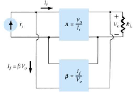
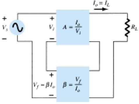
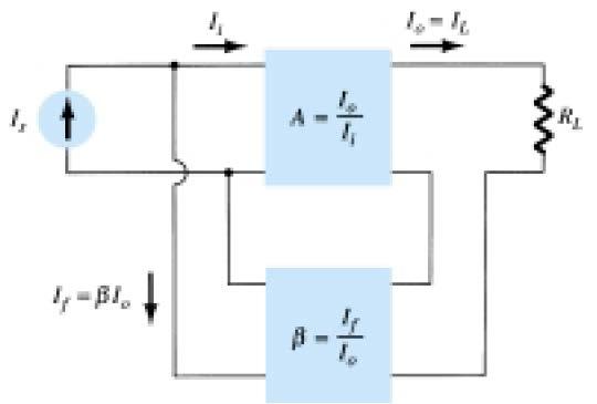
7 FEEDBACK CONNECTION TYPES 1. Voltage-series feedback 2. Voltage-shunt feedback 3. Current-series feedback 4. Current-shunt feedback 1
8 2
9 3
10 4

11 Summary of Gain, Feedback, and Gain with Feedback
12 Effect of Feedback Connection on Input and Output Impedance
.")
13 OSCILLATORs An oscillator is a circuit that produces a periodic waveform on its output with only the dc supply voltage as an input (DC- bias). The output voltage can be either sinusoidal or nonsinusoidal, depending on the type of oscillator.
14 OSCILLATORs Positive Feedback is used in some oscillators Positive feedback is characterized by the condition wherein a portion of the output voltage of an amplifier is fed back to the input with no net phase shift, resulting in a reinforcement of the output signal. This basic idea is illustrated in Figure
15 OSCILLATORs In some types of amplifiers the feedback circuit shifts the phase and an inverting amplifier is required to provide another phase shift so that there is no net phase shift. This is illustrated in Figure
16 OSCILLATORs Conditions for Oscillation Two conditions, illustrated in Figure, are required for a sustained state of oscillation: 1. The phase shift around the feedback loop must be effectively 2. The voltage gain, around the closed feedback loop (loop gain) must equal 1 (unity).a cl
17 OSCILLATORs 1- WIEN BRIDGE OSCILLATOR(sinusoidal output) Based on Wheatstone bridge. It can oscillate only at a frequency which FB has zero phase shift (this occurs only at one frequency) and loop gain equal one.
18 OSCILLATORs 1- WIEN BRIDGE OSCILLATOR(sinusoidal output) the analysis of the bridge circuit results in If, in particular, the values are R1 = R2 = R and C1 = C2 = C, the resulting oscillator frequency is
19 Report WIEN BRIDGE OSCILLATOR Drive an expression for Acl = AB and prove that A=3 at oscillation frequency.
20 2- Explain the purpose of oscillator in Figure and Drive an expression of frequency oscillation and the value of f 0?
21 Exam Explain the basic idea of Wien bridge oscillator circuit operation and drive an expression for the oscillation frequency? 2-Calculate the oscillation frequency of a Wien bridge oscillator circuit when R 1 = 10 kω, R 2 = 20 kω, and C 1 = C 2 = 1 nf. 3- What are the differences between Wien bridge oscillator, Switch-integrator oscillator and multivibrator oscillator?
22 2-Switch integrator oscillator A Practical Triangular-Wave Oscillator and square-wave oscillator also A triangular-wave oscillator using two op-amps (1- comparator 2- Integrator)
23 2-Switch integrator oscillator A triangular-wave oscillator using two op-amps (1- comparator (ON/ off switch) 2- Integrator) (1- comparator (ON/ off switch) is +ve. FB switch so the o/p voltage +ve. or ve. The great virtue of this type is that it has an excellent inherent amplitude control,(good amplitude stability) which acts very quickly. Some applications needs the oscillator (i.e PWM and PPM) and with some a suitable nonlinearity, convert the triangle wave to sine wave.
24 2-Switch integrator oscillator o/p signals of oscillator

25 2-Switch integrator oscillator Determine the frequency of oscillation of the circuit in Figure. To what value must R1 be changed to make the frequency 20 khz?
26 3- Multivibrator Bistable, monostable, and astable devices called multivibration devices


27 Thank You
Lecture # 11 Oscillators (RC Circuits)
") December 2014 Benha University Faculty of Engineering at Shoubra ECE-312 Electronic Circuits (A) Lecture # 11 Oscillators (RC Circuits) Instructor: Dr. Ahmad El-Banna Agenda Introduction Feedback Oscillators
December 2014 Benha University Faculty of Engineering at Shoubra ECE-312 Electronic Circuits (A) Lecture # 11 Oscillators (RC Circuits) Instructor: Dr. Ahmad El-Banna Agenda Introduction Feedback Oscillators
Minnesota State College Southeast ELEC 2260: Linear Integrated Circuits
 Minnesota State College Southeast ELEC 2260: Linear Integrated Circuits A. COURSE DESCRIPTION Credits: 4 Lecture Hours/Week: 2 Lab Hours/Week: 4 OJT Hours/Week: *.* Prerequisites: None Corequisites: None
21/10/58. M2-3 Signal Generators. Bill Hewlett and Dave Packard s 1 st product (1939) US patent No HP 200A s schematic
 US patent No HP 200A s schematic") M2-3 Signal Generators Bill Hewlett and Dave Packard s 1 st product (1939) US patent No.2267782 1 HP 200A s schematic 2 1 The basic structure of a sinusoidal oscillator. A positive feedback loop is formed
M2-3 Signal Generators Bill Hewlett and Dave Packard s 1 st product (1939) US patent No.2267782 1 HP 200A s schematic 2 1 The basic structure of a sinusoidal oscillator. A positive feedback loop is formed
Signal Generators and Waveform-Shaping Circuits
 CHAPTER 18 Signal Generators and Waveform-Shaping Circuits Figure 18.1 The basic structure of a sinusoidal oscillator. A positive-feedback loop is formed by an amplifier and a frequency-selective network.
WAVEFORM GENERATOR CIRCUITS USING OPERATIONAL AMPLIFIERS
 15EEE287 Electronic Circuits & Simulation Lab - II Lab #8 WAVEFORM GENERATOR CIRCUITS USING OPERATIONAL AMPLIFIERS OBJECTIVE The purpose of the experiment is to design and construct circuits to generate
Oscillator Principles
 Oscillators Introduction Oscillators are circuits that generates a repetitive waveform of fixed amplitude and frequency without any external input signal. The function of an oscillator is to generate alternating
EE 368 Electronics Lab. Experiment 10 Operational Amplifier Applications (2)
") EE 368 Electronics Lab Experiment 10 Operational Amplifier Applications (2) 1 Experiment 10 Operational Amplifier Applications (2) Objectives To gain experience with Operational Amplifier (Op-Amp). To
EE 368 Electronics Lab Experiment 10 Operational Amplifier Applications (2) 1 Experiment 10 Operational Amplifier Applications (2) Objectives To gain experience with Operational Amplifier (Op-Amp). To
Scheme I Sample Question Paper
 Sample Question Paper Marks : 70 Time: 3 Hrs. Q.1) Attempt any FIVE of the following. 10 Marks a) Classify configuration of differential amplifier. b) Draw equivalent circuit of an OPAMP c) Suggest and
EE301 ELECTRONIC CIRCUITS CHAPTER 2 : OSCILLATORS. Lecturer : Engr. Muhammad Muizz Bin Mohd Nawawi
 EE301 ELECTRONIC CIRCUITS CHAPTER 2 : OSCILLATORS Lecturer : Engr. Muhammad Muizz Bin Mohd Nawawi 2.1 INTRODUCTION An electronic circuit which is designed to generate a periodic waveform continuously at
Test Your Understanding
 074 Part 2 Analog Electronics EXEISE POBLEM Ex 5.3: For the switched-capacitor circuit in Figure 5.3b), the parameters are: = 30 pf, 2 = 5pF, and F = 2 pf. The clock frequency is 00 khz. Determine the
EC202- ELECTRONIC CIRCUITS II Unit- I -FEEEDBACK AMPLIFIER
 EC202- ELECTRONIC CIRCUITS II Unit- I -FEEEDBACK AMPLIFIER 1. What is feedback? What are the types of feedback? 2. Define positive feedback. What are its merits and demerits? 3. Define negative feedback.
Chapter 16: Oscillators
 Chapter 16: Oscillators 16.1: The Oscillator Oscillators are widely used in most communications systems as well as in digital systems, including computers, to generate required frequencies and timing signals.
Applied Electronics II
 Applied Electronics II Chapter 4: Wave shaping and Waveform Generators School of Electrical and Computer Engineering Addis Ababa Institute of Technology Addis Ababa University Daniel D./Getachew T./Abel
Hours / 100 Marks Seat No.
 17445 21415 3 Hours / 100 Seat No. Instructions (1) All Questions are Compulsory. (2) Illustrate your answers with neat sketches wherever necessary. (3) Figures to the right indicate full marks. (4) Assume
Electronics II. Previous Lecture
 Fall 2014 (Rev. 3.0) Lecture 22 Oscillators I Muhammad Tilal Department of Electrical Engineering CIIT Attock Campus The theme of this presentation is an inspiration from the one used in S2 Department
LINEAR IC APPLICATIONS
 1 B.Tech III Year I Semester (R09) Regular & Supplementary Examinations December/January 2013/14 1 (a) Why is R e in an emitter-coupled differential amplifier replaced by a constant current source? (b)
Transistor Digital Circuits
 Recapitulation Transistor Digital Circuits The transistor Operating principle and regions Utilization of the transistor Transfer characteristics, symbols Controlled switch model BJT digital circuits MOSFET
UNIVERSITI MALAYSIA PERLIS
 UNIVERSITI MALAYSIA PERLIS ANALOG ELECTRONICS II EMT 212 2009/2010 EXPERIMENT # 3 OP-AMP (OSCILLATORS) 1 1. OBJECTIVE: 1.1 To demonstrate the Wien bridge oscillator 1.2 To demonstrate the RC phase-shift
CHAPTER 3 OSCILOSCOPE AND SIGNAL CONDITIONING
 CHAPTER 3 OSCILOSCOPE AND SIGNAL CONDITIONING OUTLINE Introduction to Signal Generator Oscillator Requirement for Oscillation Positive Feedback Amplifier Oscillator Radio Frequency Oscillator Introduction
Function Generator Using Op Amp Ic 741 Theory
 Function Generator Using Op Amp Ic 741 Theory Note: Op-Amps ua741, LM 301, LM311, LM 324 & AD 633 may be used To design an Inverting Amplifier for the given specifications using Op-Amp IC 741. THEORY:
EMT212 Analog Electronic II. Chapter 4. Oscillator
 EMT Analog Electronic II Chapter 4 Oscillator Objectives Describe the basic concept of an oscillator Discuss the basic principles of operation of an oscillator Analyze the operation of RC, LC and crystal
BENE 2163 ELECTRONIC SYSTEMS
 UNIVERSITI TEKNIKAL MALAYSIA MELAKA FAKULTI KEJURUTERAAN ELEKTRONIK DAN KEJURUTERAAN KOMPUTER BENE 263 ELECTRONIC SYSTEMS LAB SESSION 3 WEIN BRIDGE OSCILLATOR Revised: February 20 Lab 3 Wien Bridge Oscillator
Summer 2015 Examination
 Summer 2015 Examination Subject Code: 17445 Model Answer Important Instructions to examiners: 1) The answers should be examined by key words and not as word-to-word as given in the model answer scheme.
Expect to be successful, expect to be liked,
 Thought of the Day Expect to be successful, expect to be liked, expect to be popular everywhere you go. Oscillators 1 Oscillators D.C. Kulshreshtha Oscillators 2 Need of an Oscillator An oscillator circuit
DHANALAKSHMI COLLEGE OF ENGINEERING DEPARTMENT OF ELECTRICAL AND ELECTRONICS ENGINEERING EC6202 ELECTRONIC DEVICES AND CIRCUITS
 DHANALAKSHMI COLLEGE OF ENGINEERING DEPARTMENT OF ELECTRICAL AND ELECTRONICS ENGINEERING EC6202 ELECTRONIC DEVICES AND CIRCUITS UNIT-I - PN DIODEAND ITSAPPLICATIONS 1. What is depletion region in PN junction?
Lecture #1 Course Introduction and Amplifier Feedback Concepts
 Summer 2015 Ahmad El-Banna Faculty of Engineering Department of Electronics and Communications GEE336 Electronic Circuits II Lecture #1 Course Introduction and Amplifier Feedback Concepts Instructor: Dr.
Multivibrators. Department of Electrical & Electronics Engineering, Amrita School of Engineering
 Multivibrators Multivibrators Multivibrator is an electronic circuit that generates square, rectangular, pulse waveforms. Also called as nonlinear oscillators or function generators. Multivibrator is basically
Lab 4 : Transistor Oscillators
 Objective: Lab 4 : Transistor Oscillators In this lab, you will learn how to design and implement a colpitts oscillator. In part II you will implement a RC phase shift oscillator Hardware Required : Pre
Precision Rectifier Circuits
 Precision Rectifier Circuits Rectifier circuits are used in the design of power supply circuits. In such applications, the voltage being rectified are usually much greater than the diode voltage drop,
LESSON PLAN. SUBJECT: LINEAR IC S AND APPLICATION NO OF HOURS: 52 FACULTY NAME: Mr. Lokesh.L, Hema. B DEPT: ECE. Portions to be covered
 LESSON PLAN SUBJECT: LINEAR IC S AND APPLICATION SUB CODE: 15EC46 NO OF HOURS: 52 FACULTY NAME: Mr. Lokesh.L, Hema. B DEPT: ECE Class# Chapter title/reference literature Portions to be covered MODULE I
An Oscillator is a circuit which produces a periodic waveform at its output with only the dc supply voltage at the input. The output voltage can be
 An Oscillator is a circuit which produces a periodic waveform at its output with only the dc supply voltage at the input. The output voltage can be either sinusoidal or non sinusoidal depending upon the
55:041 Electronic Circuits
 55:041 Electronic Circuits Oscillators Sections of Chapter 15 + Additional Material A. Kruger Oscillators 1 Stability Recall definition of loop gain: T(jω) = βa A f ( j) A( j) 1 T( j) If T(jω) = -1, then
The steeper the phase shift as a function of frequency φ(ω) the more stable the frequency of oscillation
 the more stable the frequency of oscillation") It should be noted that the frequency of oscillation ω o is determined by the phase characteristics of the feedback loop. the loop oscillates at the frequency for which the phase is zero The steeper the
It should be noted that the frequency of oscillation ω o is determined by the phase characteristics of the feedback loop. the loop oscillates at the frequency for which the phase is zero The steeper the
Operating Manual Ver.1.1
 Colpitt s Oscillator Operating Manual Ver.1.1 An ISO 9001 : 2000 company 94-101, Electronic Complex Pardesipura, Indore- 452010, India Tel : 91-731- 2570301/02, 4211100 Fax: 91-731- 2555643 e mail : info@scientech.bz
SYLLABUS. osmania university CHAPTER - 1 : OPERATIONAL AMPLIFIER CHAPTER - 2 : OP-AMP APPLICATIONS ARATORS AND CONVERTERS
 Contents i SYLLABUS osmania university UNIT - I CHAPTER - 1 : OPERATIONAL AMPLIFIER Operational Amplifiers-Characteristics, Open Loop Voltage Gain, Output Impedance, Input Impedance, Common Mode Rejection
OSCILLATORS AND WAVEFORM-SHAPING CIRCUITS
 OSILLATORS AND WAVEFORM-SHAPING IRUITS Signals having prescribed standard waveforms (e.g., sinusoidal, square, triangle, pulse, etc). To generate sinusoidal waveforms: o Positive feedback loop with non-linear
Preface... Chapter 1. Nonlinear Two-terminal Devices... 1
 Preface........................................... xi Chapter 1. Nonlinear Two-terminal Devices.................... 1 1.1. Introduction..................................... 1 1.2. Example of a nonlinear
GUJARAT TECHNOLOGICAL UNIVERSITY. INSTRUMENTATION & CONTROL ENGINEERING (17) ANALOG SIGNAL PROCESSING SUBJECT CODE: B.E.
 ANALOG SIGNAL PROCESSING SUBJECT CODE: B.E.") GUJARAT TECHNOLOGICAL UNIVERSITY INSTRUMENTATION & CONTROL ENGINEERING (17) ANALOG SIGNAL PROCESSING SUBJECT CODE: 2141706 B.E. 4 th Semester Type of course: Core Engineering Prerequisite: 1. Fundamental
GUJARAT TECHNOLOGICAL UNIVERSITY INSTRUMENTATION & CONTROL ENGINEERING (17) ANALOG SIGNAL PROCESSING SUBJECT CODE: 2141706 B.E. 4 th Semester Type of course: Core Engineering Prerequisite: 1. Fundamental
UNIT 1 MULTI STAGE AMPLIFIES
 UNIT 1 MULTI STAGE AMPLIFIES 1. a) Derive the equation for the overall voltage gain of a multistage amplifier in terms of the individual voltage gains. b) what are the multi-stage amplifiers? 2. Describe
CHADALAWADA RAMANAMMA ENGINEERING COLLEGE (AUTONOMOUS) Chadalawada Nagar, Renigunta Road, Tirupati
 Chadalawada Nagar, Renigunta Road, Tirupati") IC APPLICATIONS LABORATORY MANUAL Subject Code : 15A04507 Regulations : R15 Class : V Semester (ECE) CHADALAWADA RAMANAMMA ENGINEERING COLLEGE (AUTONOMOUS) Chadalawada Nagar, Renigunta Road, Tirupati 517
IC APPLICATIONS LABORATORY MANUAL Subject Code : 15A04507 Regulations : R15 Class : V Semester (ECE) CHADALAWADA RAMANAMMA ENGINEERING COLLEGE (AUTONOMOUS) Chadalawada Nagar, Renigunta Road, Tirupati 517
Speed Control of DC Motor Using Phase-Locked Loop
 Speed Control of DC Motor Using Phase-Locked Loop Authors Shaunak Vyas Darshit Shah Affiliations B.Tech. Electrical, Nirma University, Ahmedabad E-mail shaunak_vyas1@yahoo.co.in darshit_shah1@yahoo.co.in
R (a) Explain characteristics and limitations of op-amp comparators. (b) Explain operation of free running Multivibrator using op-amp.
 Explain characteristics and limitations of op-amp comparators. (b) Explain operation of free running Multivibrator using op-amp.") Set No: 1 1. (a) Draw the equivalent circuits of emitter coupled differential amplifier from which calculate Ad. (b) Draw the block diagram of four stage cascaded amplifier. Explain the function of each
Set No: 1 1. (a) Draw the equivalent circuits of emitter coupled differential amplifier from which calculate Ad. (b) Draw the block diagram of four stage cascaded amplifier. Explain the function of each
Figure 1: Closed Loop System
 SIGNAL GENERATORS 3. Introduction Signal sources have a variety of applications including checking stage gain, frequency response, and alignment in receivers and in a wide range of other electronics equipment.
KINGS COLLEGE OF ENGINEERING* DEPARTMENT OF ELECTRONICS AND COMMUNICATION ENGINEERING QUESTION BANK
 KINGS COLLEGE OF ENGINEERING* DEPARTMENT OF ELECTRONICS AND COMMUNICATION ENGINEERING QUESTION BANK SUB.NAME : LINEAR INTEGRATED CIRCUITS SUB CODE: EC1254 YEAR / SEMESTER : II / IV UNIT- I IC FABRICATION
Massachusetts Institute of Technology MIT
 Massachusetts Institute of Technology MIT Real Time Wireless Electrocardiogram (ECG) Monitoring System Introductory Analog Electronics Laboratory Guilherme K. Kolotelo, Rogers G. Reichert Cambridge, MA
Dev Bhoomi Institute Of Technology Department of Electronics and Communication Engineering PRACTICAL INSTRUCTION SHEET REV. NO. : REV.
 Dev Bhoomi Institute Of Technology Department of Electronics and Communication Engineering PRACTICAL INSTRUCTION SHEET LABORATORY MANUAL EXPERIMENT NO. ISSUE NO. : ISSUE DATE: July 200 REV. NO. : REV.
Group: Names: voltage calculated measured V out (w/o R 3 ) V out (w/ R 3 )
 V out (w/ R 3 )") 6.2 Laboratory Procedure / Summary Sheet Group: Names: An op amp requires connection to two different voltage levels from an external power supply, usually 15V and -15V, both of which can be provided by
6.2 Laboratory Procedure / Summary Sheet Group: Names: An op amp requires connection to two different voltage levels from an external power supply, usually 15V and -15V, both of which can be provided by
Gechstudentszone.wordpress.com
 8.1 Operational Amplifier (Op-Amp) UNIT 8: Operational Amplifier An operational amplifier ("op-amp") is a DC-coupled high-gain electronic voltage amplifier with a differential input and, usually, a single-ended
Facility of Engineering. Biomedical Engineering Department. Medical Electronic Lab BME (317) Post-lab Forms
 Post-lab Forms") Facility of Engineering Biomedical Engineering Department Medical Electronic Lab BME (317) Post-lab Forms Prepared by Eng.Hala Amari Spring 2014 Facility of Engineering Biomedical Engineering Department
Facility of Engineering Biomedical Engineering Department Medical Electronic Lab BME (317) Post-lab Forms Prepared by Eng.Hala Amari Spring 2014 Facility of Engineering Biomedical Engineering Department
FIRSTRANKER. 1. (a) What are the advantages of the adjustable voltage regulators over the fixed
 What are the advantages of the adjustable voltage regulators over the fixed") Code No: 07A51102 R07 Set No. 2 1. (a) What are the advantages of the adjustable voltage regulators over the fixed voltage regulators. (b) Differentiate betweenan integrator and a differentiator. [8+8]
Code No: 07A51102 R07 Set No. 2 1. (a) What are the advantages of the adjustable voltage regulators over the fixed voltage regulators. (b) Differentiate betweenan integrator and a differentiator. [8+8]
Assume availability of the following components to DESIGN and DRAW the circuits of the op. amp. applications listed below:
 ========================================================================================== UNIVERSITY OF SOUTHERN MAINE Dept. of Electrical Engineering TEST #3 Prof. M.G.Guvench ELE343/02 ==========================================================================================
TUNED AMPLIFIERS. Tank circuits.
 Tank circuits. TUNED AMPLIFIERS Analysis of single tuned amplifier, Double tuned, stagger tuned amplifiers. Instability of tuned amplifiers, stabilization techniques, Narrow band neutralization using coil,
Fig 1: The symbol for a comparator
 INTRODUCTION A comparator is a device that compares two voltages or currents and switches its output to indicate which is larger. They are commonly used in devices such as They are commonly used in devices
HIGH LOW Astable multivibrators HIGH LOW 1:1
 1. Multivibrators A multivibrator circuit oscillates between a HIGH state and a LOW state producing a continuous output. Astable multivibrators generally have an even 50% duty cycle, that is that 50% of
Philadelphia University Faculty of Engineering Communication and Electronics Engineering. Amplifier Circuits-IV
 Module: Electronics II Module Number: 6503 Philadelphia University Faculty o Engineering Communication and Electronics Engineering Ampliier Circuits-IV Oscillators and Linear Digital IC's: Oscillators:
DIGITAL ELECTRONICS ANALOG ELECTRONICS
 DIGITAL ELECTRONICS 1. N10 4 Bit Binary Universal shift register. 2. N22- Random Access Memory (16*4). 3. N23- Read Only Memory. 4. N4-R-S/D-T Flip flop, characteristic and comparison. 5. Master Slave
PROPOSED SCHEME OF COURSE WORK
 PROPOSED SCHEME OF COURSE WORK Course Details: Course Title : LINEAR AND DIGITAL IC APPLICATIONS Course Code : 13EC1146 L T P C : 4 0 0 3 Program: : B.Tech. Specialization: : Electrical and Electronics
Question Paper Code: 21398
 Reg. No. : Question Paper Code: 21398 B.E./B.Tech. DEGREE EXAMINATION, MAY/JUNE 2013 Fourth Semester Electrical and Electronics Engineering EE2254 LINEAR INTEGRATED CIRCUITS AND APPLICATIONS (Regulation
EE2254 LINEAR INTEGRATED CIRCUITS UNIT-I IC FABRICATION
 DEPARTMENT OF ELECTRICAL AND ELECTRONICS ENGINEERING Question bank EE2254 LINEAR INTEGRATED CIRCUITS UNIT-I IC FABRICATION 1. Mention the advantages of integrated circuits. 2. Write down the various processes
Oscillators. An oscillator may be described as a source of alternating voltage. It is different than amplifier.
 Oscillators An oscillator may be described as a source of alternating voltage. It is different than amplifier. An amplifier delivers an output signal whose waveform corresponds to the input signal but
CHARACTERIZATION OF OP-AMP
 EXPERIMENT 4 CHARACTERIZATION OF OP-AMP OBJECTIVES 1. To sketch and briefly explain an operational amplifier circuit symbol and identify all terminals. 2. To list the amplifier stages in a typical op-amp
Facility of Engineering. Biomedical Engineering Department. Medical Electronic Lab BME (317) Pre-Report Forms
 Pre-Report Forms") Facility of Engineering Biomedical Engineering Department Medical Electronic Lab BME (317) Pre-Report Forms Prepared by Eng.Hala Amari Spring 2014 Facility of Engineering Biomedical Engineering Department
Facility of Engineering Biomedical Engineering Department Medical Electronic Lab BME (317) Pre-Report Forms Prepared by Eng.Hala Amari Spring 2014 Facility of Engineering Biomedical Engineering Department
PHYS225 Lecture 18. Electronic Circuits
 PHYS225 Lecture 18 Electronic Circuits Oscillators and Timers Oscillators & Timers Produce timing signals to initiate measurement Periodic or single pulse Periodic output at known (controlled) frequency
Linear Integrated Circuits and Applications
 Dhanalakshmi Srinivasan Engineering College - Perambalur Department of EEE QUESTION BANK Linear Integrated Circuits and Applications UNIT-I ICs FABRICATION 1. Mention the advantages of integrated circuits.
Chapter.8: Oscillators
 Chapter.8: Oscillators Objectives: To understand The basic operation of an Oscillator the working of low frequency oscillators RC phase shift oscillator Wien bridge Oscillator the working of tuned oscillator
MODEL ANSWER SUMMER 17 EXAMINATION Subject Title: Linear Integrated Circuit Subject Code:
 MODEL ANSWER SUMMER 17 EXAMINATION Subject Title: Linear Integrated Circuit Subject Code: Important Instructions to examiners: 1) The answers should be examined by key words and not as word-to-word as
Discrete Op-Amp Kit MitchElectronics 2019
 Discrete Op-Amp Kit MitchElectronics 2019 www.mitchelectronics.co.uk CONTENTS Introduction 3 Schematic 4 How It Works 5 Materials 9 Construction 10 Important Information 11 Page 2 INTRODUCTION Even if
Advanced Regulating Pulse Width Modulators
 Advanced Regulating Pulse Width Modulators FEATURES Complete PWM Power Control Circuitry Uncommitted Outputs for Single-ended or Push-pull Applications Low Standby Current 8mA Typical Interchangeable with
Table of Contents Lesson One Lesson Two Lesson Three Lesson Four Lesson Five PREVIEW COPY
 Oscillators Table of Contents Lesson One Lesson Two Lesson Three Introduction to Oscillators...3 Flip-Flops...19 Logic Clocks...37 Lesson Four Filters and Waveforms...53 Lesson Five Troubleshooting Oscillators...69
Introduction to Simulation using EDWinXP
 Introduction to Simulation using EDWinXP Introduction to Simulation using EDWinXP First Edition Copyright Notice ALL RIGHTS RESERVED. Any unauthorized reprint or use of this material is prohibited. No
An input resistor suppresses noise and stray pickup developed across the high input impedance of the op amp.
 When you have completed this exercise, you will be able to operate a voltage follower using dc voltages. You will verify your results with a multimeter. O I The polarity of V O is identical to the polarity
Devices and Op-Amps p. 1 Introduction to Diodes p. 3 Introduction to Diodes p. 4 Inside the Diode p. 6 Three Diode Models p. 10 Computer Circuit
 Contents p. v Preface p. ix Devices and Op-Amps p. 1 Introduction to Diodes p. 3 Introduction to Diodes p. 4 Inside the Diode p. 6 Three Diode Models p. 10 Computer Circuit Analysis p. 16 MultiSIM Lab
University of Pittsburgh
 University of Pittsburgh Experiment #6 Lab Report Active Filters and Oscillators Submission Date: 7/9/28 Instructors: Dr. Ahmed Dallal Shangqian Gao Submitted By: Nick Haver & Alex Williams Station #2
Operating Manual Ver.1.1
 Phase Shift Oscillator Operating Manual Ver.1.1 An ISO 9001 : 2000 company 94-101, Electronic Complex Pardesipura, Indore- 452010, India Tel : 91-731- 2570301/02, 4211100 Fax: 91-731- 2555643 e mail :
Electronic PRINCIPLES
 MALVINO & BATES Electronic PRINCIPLES SEVENTH EDITION Chapter 22 Nonlinear Op-Amp Circuits Topics Covered in Chapter 22 Comparators with zero reference Comparators with non-zero references Comparators
NOORUL ISLAM COLLEGE OF ENGG, KUMARACOIL. DEPARTMENT OF ELECTRONICS AND COMMUNICATION ENGG. SUBJECT CODE: EC 1251 SUBJECT NAME: ELECTRONIC CIRCUITS-II
 NOORUL ISLAM COLLEGE OF ENGG, KUMARACOIL. DEPARTMENT OF ELECTRONICS AND COMMUNICATION ENGG. SUBJECT CODE: EC 1251 SUBJECT NAME: ELECTRONIC CIRCUITS-II Prepared by, C.P.SREE BALA LEKSHMI (Lect/ECE) ELECTRONICS
are equally illuminated, the lamp I 1
 Student ID: 21643431 Exam: 387018RR - PRACTICAL EXERCISE ADVANCED ELECTRONIC COMPONENTS When you have completed your exam and reviewed your answers, click Submit Exam. Answers will not be recorded until
Assignment 11. 1) Using the LM741 op-amp IC a circuit is designed as shown, then find the output waveform for an input of 5kHz
 Using the LM741 op-amp IC a circuit is designed as shown, then find the output waveform for an input of 5kHz") Assignment 11 1) Using the LM741 op-amp IC a circuit is designed as shown, then find the output waveform for an input of 5kHz Vo = 1 x R1Cf 0 Vin t dt, voltage output for the op amp integrator 0.1 m 1
Assignment 11 1) Using the LM741 op-amp IC a circuit is designed as shown, then find the output waveform for an input of 5kHz Vo = 1 x R1Cf 0 Vin t dt, voltage output for the op amp integrator 0.1 m 1
EE 230 Lecture 23. Nonlinear Op Amp Applications. Waveform Generators
 EE 230 Lecture 23 Nonlinear Op Amp Applications Waveform Generators Quiz 7 An oscillator based upon a comparator with hysteresis is shown. If STAH =2 and SATL =-2, determine the peak value of And the number
MARIA COLLEGE OF ENGINEERING AND TECHNOLOGY, ATTOOR UNIT-1. Feedback Amplifiers
 MARIA COLLEGE OF ENGINEERING AND TECHNOLOGY, ATTOOR DEPARTMENT OF ELECTRONICS AND COMMUNICATION ENGINEERING ELECTRONIC CIRCUITS-II 2 MARKS QUESTIONS & ANSWERS UNIT-1 Feedback Amplifiers 1. What is meant
Sub Code & Name: EC2251- ELECTRONIC CIRCUITS II Unit : I Branch : ECE Year:II
 Unit : I Branch : ECE Year:II Page 01 of 06 UNIT 1 FEEDBACK AMPLIFIERS 9 Block diagram, Loop gain, Gain with feedback, Effects of negative feedback Sensitivity and desensitivity of gain, Cut-off frequencies,
ELECTRONICS ADVANCED SUPPLEMENTARY LEVEL
 ELECTRONICS ADVANCED SUPPLEMENTARY LEVEL AIMS The general aims of the subject are : 1. to foster an interest in and an enjoyment of electronics as a practical and intellectual discipline; 2. to develop
Sai Nath University. Assignment For Diploma in E&C 4 th Sem.
 Sai Nath University Assignment For Diploma in E&C 4 th Sem. The Assignment will consist of two parts, A and B. Part A will have 5 short answer questions(40-60 words) of 4 marks each. Part B will have 4
EE431 Lab 1 Operational Amplifiers
 Feb. 10, 2015 Report all measured data and show all calculations Introduction The purpose of this laboratory exercise is for the student to gain experience with measuring and observing the effects of common
GUJARAT TECHNOLOGICAL UNIVERSITY, AHMEDABAD, GUJARAT. Course Curriculum ANALOG ELECTRONICS. (Code: ) Electronics and Communication Engineering
 Electronics and Communication Engineering") GUJARAT TECHNOLOGICAL UNIVERSITY, AHMEDABAD, GUJARAT Course Curriculum ANALOG ELECTRONICS (Code: 333110) Diploma Programme in which this course is offered Semester in which offered Electronics and Communication
GUJARAT TECHNOLOGICAL UNIVERSITY, AHMEDABAD, GUJARAT Course Curriculum ANALOG ELECTRONICS (Code: 333110) Diploma Programme in which this course is offered Semester in which offered Electronics and Communication
Lecture 28 RC Phase Shift Oscillator using Op-amp
 Integrated Circuits, MOSFETs, OP-Amps and their Applications Prof. Hardik J Pandya Department of Electronic Systems Engineering Indian Institute of Science, Bangalore Lecture 28 RC Phase Shift Oscillator
Feedback and Oscillator Circuits
 Chapter 14 Chapter 14 Feedback and Oscillator Circuits Feedback Concepts The effects of negative feedback on an amplifier: Disadvantage Lower gain Advantages Higher input impedance More stable gain Improved
APPLIED ELECTRONIC CIRCUITS
 SRM UNIVERSITY DEPARTMENT OF BIOMEDICAL ENGINEERING ODD Semester-2014-2015 BM1005 APPLIED ELECTRONIC CIRCUITS Course Code: BM1005 Course Title: APPLIED ELECTRONIC CIRCUITS Sem: III SEM B. Tech Second Year
EC0206 LINEAR INTEGRATED CIRCUITS
 SRM UNIVERSITY FACULTY OF ENGINEERING AND TECHNOLOGY SCHOOL OF ELECTRONICS AND ELECTRICAL ENGINEERING DEPARTMENT OF ECE COURSE PLAN Course Code : EC0206 Course Title : Linear Integrated Circuits Semester
Basic Operational Amplifier Circuits
 Basic Operational Amplifier Circuits Comparators A comparator is a specialized nonlinear op-amp circuit that compares two input voltages and produces an output state that indicates which one is greater.
Analog Electronic Circuits Lab-manual
 2014 Analog Electronic Circuits Lab-manual Prof. Dr Tahir Izhar University of Engineering & Technology LAHORE 1/09/2014 Contents Experiment-1:...4 Learning to use the multimeter for checking and indentifying
GATE: Electronics MCQs (Practice Test 1 of 13)
") GATE: Electronics MCQs (Practice Test 1 of 13) 1. Removing bypass capacitor across the emitter leg resistor in a CE amplifier causes a. increase in current gain b. decrease in current gain c. increase
GATE: Electronics MCQs (Practice Test 1 of 13) 1. Removing bypass capacitor across the emitter leg resistor in a CE amplifier causes a. increase in current gain b. decrease in current gain c. increase
Experiment 1: Amplifier Characterization Spring 2019
 Experiment 1: Amplifier Characterization Spring 2019 Objective: The objective of this experiment is to develop methods for characterizing key properties of operational amplifiers Note: We will be using
Chapter 13 Oscillators and Data Converters
 Chapter 13 Oscillators and Data Converters 13.1 General Considerations 13.2 Ring Oscillators 13.3 LC Oscillators 13.4 Phase Shift Oscillator 13.5 Wien-Bridge Oscillator 13.6 Crystal Oscillators 13.7 Chapter
SRM UNIVERSITY FACULTY OF ENGINEERING AND TECHNOLOGY SCHOOL OF ELECTRONICS AND ELECTRICAL ENGINEERING DEPARTMENT OF EEE. Section
 SRM UNIVERSITY FACULTY OF ENGINEERING AND TECHNOLOGY SCHOOL OF ELECTRONICS AND ELECTRICAL ENGINEERING DEPARTMENT OF EEE Course Code : EE0305 Course Title : LINEAR INTEGRATED CIRCUITS Semester : V Course
ASTABLE MULTIVIBRATOR
 555 TIMER ASTABLE MULTIIBRATOR MONOSTABLE MULTIIBRATOR 555 TIMER PHYSICS (LAB MANUAL) PHYSICS (LAB MANUAL) 555 TIMER Introduction The 555 timer is an integrated circuit (chip) implementing a variety of
IFB270 Advanced Electronic Circuits
 IFB270 Advanced Electronic Circuits Chapter 12: The operational amplifier Prof. Manar Mohaisen Department of EEC Engineering Review of the Precedent Lecture Introduce the four layer diode Introduce the
DEPARTMENT OF ELECTRICAL ENGINEERING AND COMPUTER SCIENCE MASSACHUSETTS INSTITUTE OF TECHNOLOGY CAMBRIDGE, MASSACHUSETTS 02139
 DEPARTMENT OF ELECTRICAL ENGINEERING AND COMPUTER SCIENCE MASSACHUSETTS INSTITUTE OF TECHNOLOGY CAMBRIDGE, MASSACHUSETTS 019.101 Introductory Analog Electronics Laboratory Laboratory No. READING ASSIGNMENT
11. Chapter: Amplitude stabilization of the harmonic oscillator
 Punčochář, Mohylová: TELO, Chapter 10 1 11. Chapter: Amplitude stabilization of the harmonic oscillator Time of study: 3 hours Goals: the student should be able to define basic principles of oscillator
HOME ASSIGNMENT. Figure.Q3
 HOME ASSIGNMENT 1. For the differential amplifier circuit shown below in figure.q1, let I=1 ma, V CC =5V, v CM = -2V, R C =3kΩ and β=100. Assume that the BJTs have v BE =0.7 V at i C =1 ma. Find the voltage