Manual for the 70cm-FM/FSK-Transceiver T7F
|
|
|
- Esmond Harrington
- 5 years ago
- Views:
Transcription
1 Manual for the 70cm-FM/FSK-Transceiver T7F Holger Eckardt DF2FQ Kirchstockacherstr. 33 D Hohenbrunn 4199HE
2 Technical Data General Frequency range: Channel spacing: Receive-transmit delay time: Temperature range: Power supply: Size: MHz 12.5 and 25kHz <30ms C V, 60mA RX, max. 2.5A TX 145 x 75 x 22 mm Receiver Sensitivity: -118dBm for 20dB SINAD AF frequency response: 1Hz... 7,000 Hz (-3dB) AF total harmonic distortion: <1% Intermodulation response: -54dB (3-tone test) Adjacent channel response: <-56dB Spurious response: <-60dB (1st image), <51dB (2nd image) Transmitter RF power: 1.5W at 7V, 6.5W at 12V AF frequency response: 1Hz... 15,000 Hz (-3dB) AF distortion: <1% Spurious transmission: -66dBc (1st harmonic), <-75dBc else Spurious transients: <-40dBc on the adjacent channel Circuit description The circuit diagram is spread over four sheets. Figure 1 shows the synthesizer with modulation circuit, figure 2 the receive section, figure 3 the transmitter and figure 4 the control circuit. Synthesizer Heart of the synthesizer is the VCO (voltage controlled oscillator) which supplies RX and TX as well. A helix coil guarantees low oscillator noise and low sensitivity against microphony. Separate varicaps are used for tuning and modulation. The VCO works on half the transmission frequency to decouple it from interference by the power amplifier. A doubler follows the VCO, which again is followed by a buffer amplifier. The attenuator between the stages gives some additional decoupling. In the collector circuit of the buffer a notch filter is used to suppress the VCO frequency. The synthesizer chip MB1504 controls the VCO. The current source of the internal phase detector is much too weak for the fast switching time that is needed, so there is an push-pull amplifier placed on the output of the phase discriminator. It drives the low-impedance loop filter. The frequency response would be insufficient for packet radio if we would apply the modulation signal only to the VCO. Below the cut-off frequency of the loop filter the deviation would decrease with 6dB per octave. Since the cut-off frequency is 700Hz on 10Hz we wouldn t have hardly any detectable signal of the modulation. Therefore the reference oscillator is modulated as well. The frequency response of this path is complementary to that of the VCO so both paths together give a perfectly flat response. The reference oscillator is also used to drive the second receiver mixer. Since the reference must be an integer multiple of 25kHz the IF (intermediate frequency) becomes 450kHz instead of the conventional 455kHz. This has to be considered at the crystal filter. 2
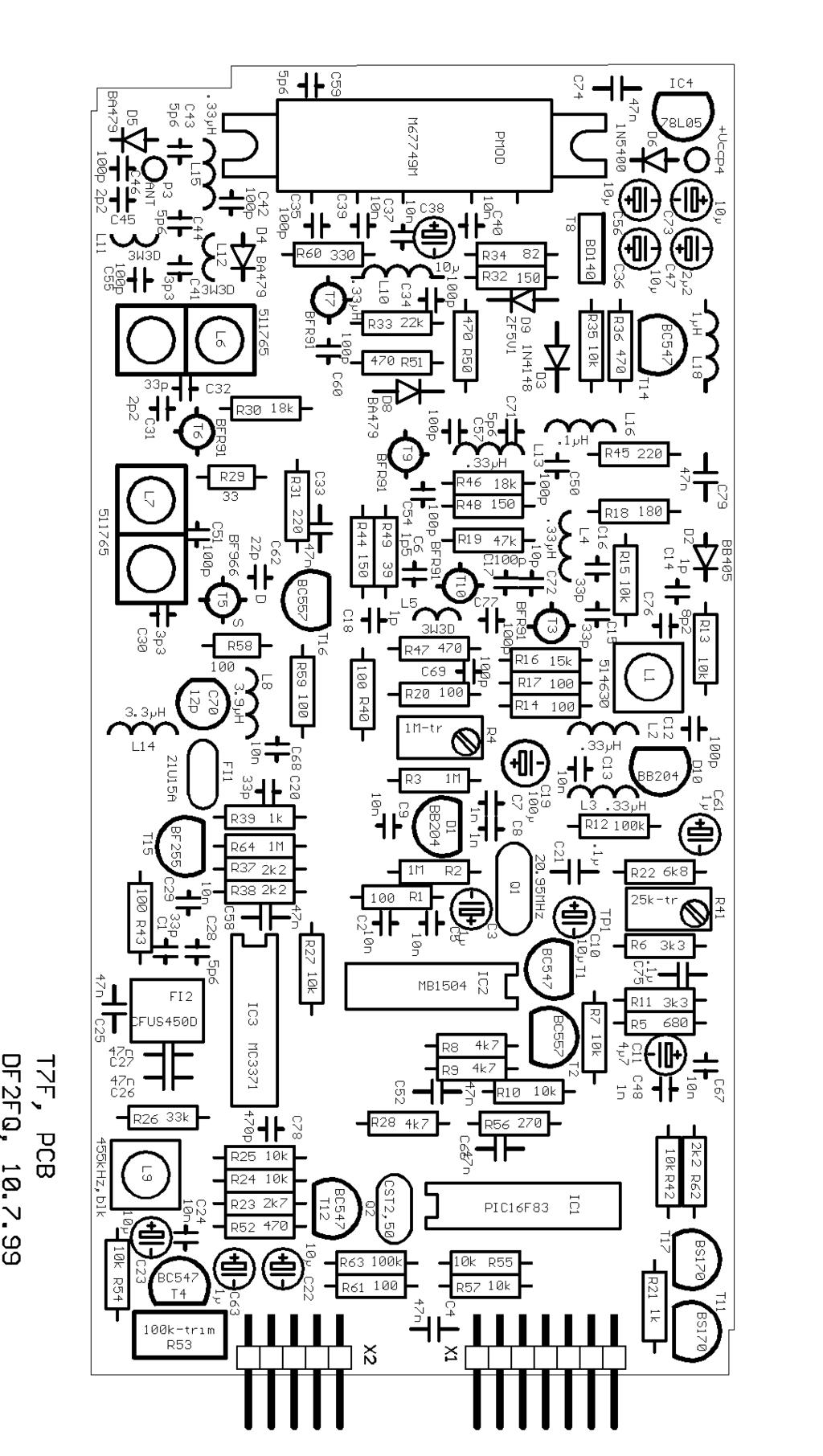
3 Receiver Two helix filters act as pre-selector, one ahead and one behind the low noise amplifier T6. The dualgate FET (field effect transistor) T5 acts as mixer. To obtain a good intermodulation response both stages are driven with a relatively high supply current. Printed inductors match the high impedance gates of the FET. The drain provides the IF signal. Due to the strong requirements for a flat group delay a trimmer is used to optimize the matching of the crystal filter. The filter is followed by a buffer amplifier and than by the IF circuit MC3371. Beside the 2nd mixer this IC contains a limiting amplifier, the demodulator, a RSSI (radio signal strength indicator) circuit and an operational amplifier. The latter is used as a 2nd order low-pass filter to suppress IF spurious on the output signal. The ceramic filter for the 2nd IF is internally compensated for flat group delay response. The RSSI output provides a current which is proportional to the logarithm of the RF (radio frequency) input voltage. With a buffer amplifier this signal is good to drive a S-meter. It is also used to generate a fast DCD (data carrier detect) signal which is advantageous in particular when operating over multimode digipeaters. Within the dynamic range of the RSSI the potentiometer R53 determines the trigger threshold. Transmitter The driver T7 boosts the VCO signal up to 30mW. This is sufficient to drive the PA (power amplifier) module which at 12V supply voltage delivers an output power of 7W. Behind the low pass filter and the pin diode switch a power of 6W or more is available. T8 and T14 generates a linear ramp with a time constant of 5ms. The slow ramping of the PA avoids spurious signals in the adjacent channels. A 5V regulator supplies all stages of the transceiver except driver and PA module. These gets the unregulated supply voltage directly. Control circuit A micro controller IC is used to control the whole transceiver. It polls the PTT (push to talk) line, programs the synthesizer chip, switches receiver and transmitter path in a well defined time scheme and checks the channel select ports. The required software is stored in the EEPROM within the chip. Construction The PCB (printed circuit board) artwork for the transceiver is shown in figure 5. It fits on an area of 144 x 72mm. You can find a part list at the end of this text. Those components which are marked with n.p. in the schematics must not be placed on the board. Values of the capacitors are partly printed in exponential expression, 102 e.g. means 1nF, 473 means 47nF. Basically it is the same as with resistors only instead of colors numbers are used. It is recommended to start the construction by fitting the low-profile parts (resistors, RF-transistors, etc.), then the capacitors and AF-transistors and finally the larger parts such as crystals and filters. No sockets must be used for the ICs except for IC1. This one however should be placed on a socket as it makes software update much easier. The flat RF transistors have one long terminal, for the bipolar types it is the collector for the FET it is the drain. The type numbers always look away from the PCB. The heat sink of T8 looks to the border of the PCB. D2 (BB405) normally does not have any printed type number on it, it can be recognized by the black body with a white ring. The resonator Q2 already includes the two feed back capacitors. It has a bubble-shaped blue body with three terminals. Three inductors have to be wound manually. They are marked with 3T3D in the schematics. This means 3 turns, 3mm diameter. Silver plated copper wire of 0.4mm diameter should be used. The terminals of L5 and L11 are stretched to the distance of the through-holes. L12 is wound as tight as 3
4 possible. All other fixed inductors look like thick resistors, they are coded by colors. L14 (3.3uH, orange orange gold) and L2-4 (0.33uH, orange orange silver) look very similar, so do L16 (0.1uH, brown black silver) and L18 (1uH, brown black gold). The only component which is soldered from the rear side of the board is the power module. It is mounted in such a way that the heat sink looks away from the PCB. The distance between the flange and the PCB should be 4mm. This is ensured by two 4mm-spacers. The construction step by step: Preparing the housing: Insert the BNC in the wall connector without washer and tighten the nut. Insert the feed-through capacitor from outside the wall and solder from inside. Bend the inner terminal so that it later fits into the hole on the PCB. Stick the two side walls of the housing together with the lower cover and solder the edges of the walls from inside. Preparing the PCB (considered that all components are fitted): Solder the four spacers concentric on the pads of the PCB, the 5mm parts on the middle pads, the 4mm ones below the PA module. Solder a 3cm piece of wire to the antenna pad for the BNC connector. Assembly: Slip the PCB into the housing frame, connector pins first. Fit frame and PCB onto the lower cover. Adjust the PCB so that the flange of the PA module flushes with the cover. Solder all 13 pads of the PCB to the side walls. Solder middle pin of BNC connector and feed-through capacitor. Fit the aluminum plate onto the lower cover, insert the four screws from outside into the holes and tighten the nuts from the PCB side. Stick the upper cover onto the frame. For usual packet radio operation with not more 30% transmitter duty cycle a 2.5mm aluminum plate is absolutely sufficient as heat sink. Should the transceiver be designed for heavy duty use, e.g. at a digipeater, a heat sink with less than 5K/W is necessary. On the PCB is space for a strong diode (D6) in series with the power connector to prevent damage from the transceiver by applying wrong polarity. Unfortunately the holes are too small for it s legs. So either you drill them up or you can simply mount the diode outside the housing as well. Setting up the device The transceiver has 9 adjustment points, anyway the adjustment is simple. The following test equipment is required: Digital multimeter, Frequency counter capable to measure at least 30MHz with a sensitivity of 20mV, Oscilloscope, AF generator for sinus and square wave signals, A stable source for a 70cm Signal with an adjustable level between -60 and -90dBm (in case you don t have access to a signal generator a portable transceiver with 0.5 W RF power in 30m distance will do). A receiver for the 70cm band with good demodulation capabilities (e.g. a scanner receiver with FMwide mode or a 9k6-capable radio). 4
5 A non-metalic screwdriver for tuning cores and trimmers Start by connecting the 12V power supply voltage to the board. The current consumption should be about 60mA. After two minutes warming up connect the frequency counter to Pin 2 of IC3 (MC3371). This is the buffered output of the reference oscillator. The voltage at this point is below 100mVss. Adjust the frequency with R4 exactly to MHz. Please keep in mind that every Hz offset produces 20 times the offset on the final frequency. This has also to be considered at the accuracy of the counter. Due to the big coupling capacitors this adjustment reacts relatively slow. Now enter a receive frequency of MHz. In the next chapter it is explained how to enter frequencies in general, for the first you can just switch to channel 0 by leaving all pins of X1 open. Turn L1 clockwise until the voltage at test pad TP1 is 0.8V. Enter a receive frequency of 435MHz by connecting pin 1 with pin 2 and pin 5 with pin 6 of X1 (this settings of course works only if the PIC is in its original state and no other frequencies have been programmed into the memory). Set the RF-generator to the same frequency and connect a digital voltmeter to the RSSI terminal (pin 10 of X2). The DCD trimmer R54 should be in 12 o clock position because the RSSI voltage depends a little on the setting of R54. Without input signal the RSSI voltage should be between 0.4 and 0.8 V. Depending on the RF signal the voltage increases. Turn the cores of L6 and L7 and C70 recursively until the RSSI value reaches a maximum. If voltage reaches 3.5V decrease the RF input level to continue the procedure. The next step is to modulate the generator with a 1kHz sinewave signal of 3kHz deviation. Connect the oscilloscope to the AF output terminal (pin 8 of X2). Turn the core of L9 so that the amplitude of the output signal reaches a maximum and minimize the distortion with C70. An THD value of below 1% should be reached. You can estimate the distortion very well if you have a dual trace oscilloscope where you apply the original signal to the second channel. The receive path is now ready to use. Before tuning the transmitter make sure that the heat sink is mounted properly and the PCB is soldered firmly in the housing. Reduce the supply voltage to 7.5 volts and connect an AF generator to the modulation input terminal (pin 6 of X2). The generator should be set to an squarewave output of 400mVss at a frequency of 100Hz. Plug a dummy load or a watt meter to the BNC connector and then put the PTT terminal (pin 4 of X2) to ground. The output power should be about 1.5 W. Check the modulation with a separate receiver tuned to the transmit frequency. An oscilloscope connected to the output of the receiver most likely will show a heavily distorted squarewave signal at first. Turn R41 clockwise until the roof of the squarewave has a perfectly flat shape. At last set the supply voltage back to 12V and check the output power. It should be 6W or more. User interface The transceiver has a 10 pin (X2) and a 14 pin (X1) connector. Table 2 shows the pinout. Pin 1 is located in the upper right corner of the connector with view on the pins. There are female plugs available for flat cable. X1 is used for frequency control, X2 for the link to TNC or modem. X1: Pin Signal Pin Signal 1 D0 2 n.c. 3 D1 4 n.c. 5 D2 6 n.c. 7 D3 8 TXD 9 n.c. 10 RXD 11 PTT / 25kHz 13 GND 14 +5V 5
6 X2: Pin Signal Pin Signal 1 GND 2 +5V 3 DCD 4 PTT 5 GND 6 MODULATION 7 GND 8 AF-OUTPUT 9 n.c. 10 RSSI n.c. = do not connect Entering frequencies The current version 1.4 of the control software allows the use of 12.5 and 25kHz channel spacing. Due to technical reasons the switching time between receive and transmit mode is slightly longer at 12.5 khz operation. Pin 12 of X1 selects the spacing. By default (pin open) 12.5kHz is selected. If the pin is on +5V 25kHz operation is active. The transceiver covers the whole 70cm Band, for repeater operation you can choose any frequency offset. The device has a memory for 10 pairs of channels for receive and transmit. The channel is selected by D0 to D3 (pins 1,3,5,7 of X1) in BCD code. This can be done with a BCD switch or by jumpers (jumper inserted=1, pin open = 0). The common terminal of the BCD switch must be connected to ground. D0 is the least significant, D3 the most significant bit. The jumpers can be plugged on adjacent pins, e.g. 1 and 2, 3 and 4 etc. Even that n.c. means no connection, the microcontroller sets those pins to ground during normal operation. In the original configuration the 10 channels are pre-programmed with 430, 431,... to 439 MHz. This is true only if 25kHz spacing is selected. Programming of the desired frequencies is done through the serial interface. You need a computer with a RS232 interface (e.g. COM1 or COM2 at DOS computers) and any V24-terminal software which is capable to send characters to it. Such a software is part of most operating systems. Depending on the connector type please regard to table 3 for the exact configuration. Signal T7F/X1 SUB-D 25 SUB-D 9 RXD TXD GND The interface parameters must be set on the computer to 1200 BPS (bit per second), no parity, two stop bits, no local echo, no protocol (e.g. for DOS: MODE COM N). Now a simple string of characters can be entered to allocate a frequency to a particular memory location: Cntttrrr[RETURN] C means the upper case C on the keyboard (HEX 43), n is the memory location 0 to 9 you want to program. rrr is the channel number for the receiver and ttt that for the transmitter. The channel number has always 3 digits even if the first digit is zero. It can be computed from the following formula: N=(f )/R N is the channel number, f is the desired operation frequency for RX or TX in khz, and R is the channel spacing (12.5 or 25kHz). The string is not editable, if you make a mistake press enter and start again. To make it clear here two examples spacing: Memory location 0, receive frequency MHz, transmit frequency Mhz, 25kHz spacing: 6
7 The string is C Memory location 8, receive and transmit frequency Mhz, 12.5kHz spacing: The string is C All characters you enter are echoed by the T7F, this is a good way to check the physical link between the devices. If you press E (HEX 45) you get a hex dump of the 40 bytes of memory. If you switch on the power of the T7F the version number of the software is sent on the TXD line. Modem signals AF input and output is compatible to most of the existing packet radio modems. The level of the output at 3kHz deviation is 1Vss, the modulation input needs mVss to get a deviation of 3kHz. Some modems provide a DC level on the modulation signal. In this case you have to insert a 10µF capacitor in the modulation line (plus pole to the modem). The transceiver provides a fast DCD signal. Most modems generate a DCD signal internally from the data signal. If you operate on a multi mode digipeater it can happen that the internal DCD does not recognize the other mode, so you need the external DCD from the transceiver. Adjust the sensitivity with R53. If it is turned fully counter clockwise the function is disabled. The delay time to key the transmitter is below 30ms so TXD 3 should be OK for packet radio operation. However some modems takes a certain amount of time by itself for switching so the TX delay can be considerably longer occasionally. Voice operation and what you can do else With little additional effort the transceiver also can be used for voice operation. A full description and an extension PCB is available on request from the author. Of course the radio can be used for 1200 BPS packet radio as well, no modification is required. If you want to operate with BPS you need wider IF filters. FI1 must be replaced by a 21U30A, for FI2 a CFUS450BY is required, C78 should have 330pF instead of 470pF. Postscript The published design may be used by everybody for private purposes. Each commercial usage, also from parts of the design requires a permission from the author. The author rejects any liabilities for damages which result from construction or use of the device. Appropriate construction considered the design is compliant to all requirements of the new European standard for amateur radio equipment ETS as well as to the EMC standard EN However the device is not certified by any administrative body. For questions and further information the author is available in packet radio or by under df2fq@amsat.org. 7
8 Fig. 1 8
9 Fig. 2 9
10 Fig. 3 10
11 Fig. 4 11
12 Fig. 5 12

13 Fig. 6, Jumper position (X1) Fig. 7, A picture of the assembled unit 13
14 Partlist C1 33p C2 10n C3 1µF C4 47n C5 10n C6 1p5 C7 1n C8 1n C9 10n C10 10µF C11 4u7 C12 100p C13 10n C14 1p C15 33p C16 33p C17 100p C18 1p C19 100µF C20 33p C21.1µF C22 10µF C23 10µF C24 10n C25 47n C26 47n C27 47n C28 5p6 C29 10n C30 3p3 C31 2p2 C32 33p C33 47n C34 100p C35 100p C36 10µF C37 10n C38 10µF C39 10n C40 10n C41 3p3 C42 100p C43 5p6 C44 5p6 C45 2p2 C46 100p C47 2u2 C48 1n C50 100p C51 100p C52 47n C54 100p C55 100p C56 10µF C57 100p C58 47n C59 5p6 C60 100p C61 1µF C62 22p C63 1µF C66 47n C67 10n C68 10n C69 100p C70 12p-trim C71 5p6 C72 10p C73 10µ C74 47n C75.1µF C76 8p2 C77 100p C78 470p C79 47n D1 BB204 D2 BB405 D3 1N4148 D4 BA479 D5 BA479 D6 1N5400 or SB320 D8 BA479 D9 BZX55-5V1 D10 BB204 FI1 21U15A FI2 CFUS450DY IC1 PIC16F83 IC2 MB1504 IC3 MC3371 IC4 78L05 L L2.33µH L3.33µH L4.33µH L5 3W3D L L L8 3.9µH L9 455kHz,blk L10.33µH L11 3W3D L12 3W3D L13.33µH L14 3.3µH L15.33µH L16.1µH L18 1µH PMOD M67749M Q MHz Q2 CST2.50 R1 100 R2 1M R3 1M R4 1M-trim R5 680 R6 3k3 R7 10k R8 4k7 R9 4k7 R10 10k R11 3k3 R12 100k R13 10k R R15 10k R16 15k R R R19 47k R R21 1k R22 6k8 R23 2k7 R24 10k R25 10k R26 33k R27 10k R28 4k7 R29 33 R30 18k R R R33 22k R34 82 R35 10k R R37 2k2 R38 2k2 R39 1k R R41 25k-trim R42 10k R R R R46 18k R R R49 39 R R R R53 100k-trim R54 10k R55 10k R R57 10k R R R R R62 2k2 R63 100k R64 1M T1 BC547 T2 BC557 T3 BFR91 T4 BC547 T5 BF966 T6 BFR91 T7 BFR91 T8 BD140 T9 BFR91 T10 BFR91 T12 BC547 T11 BS170 T14 BC547 T15 BF255 T16 BC557 T17 BS170 X1 2X07/90 X2 2X05/90 14
Construction Manual 6m-Linear-Transverter XV6/10
 Construction Manual 6m-Linear-Transverter XV6/10 Holger Eckardt DF2FQ Kirchstockacherstr. 33 D-85662 Hohenbrunn 2606 Technical data exciter frequency: 28... 30 MHz RF frequency: 50... 52 MHz supply voltage:
Construction Manual 4m-Linear-Transverter XV4-15
 Construction Manual 4m-Linear-Transverter XV4-15 Holger Eckardt DF2FQ Kirchstockacherstr. 33 D-85662 Hohenbrunn 3207 Technical data exciter frequency: 21.0... 21.5 MHz RF frequency: 70.0.. 70.5 MHz supply
MAINTENANCE MANUAL RF BOARD 19D901835G1 ( MHz) 19D901835G2 ( MHz) FOR MVS
 19D901835G2 ( MHz) FOR MVS") D MAINTENANCE MANUAL F BOAD 19D901835G1 (136-153 MHz) 19D901835G2 (150-174 MHz) FO MVS TABLE OF CONTENTS DESCIPTION............................................... Front Cover CICUIT ANALYSIS..............................................
D MAINTENANCE MANUAL F BOAD 19D901835G1 (136-153 MHz) 19D901835G2 (150-174 MHz) FO MVS TABLE OF CONTENTS DESCIPTION............................................... Front Cover CICUIT ANALYSIS..............................................
MAINTENANCE MANUAL TRANSMITTER/RECEIVER BOARD CMN-234A/B FOR MLSU141 & MLSU241 UHF MOBILE RADIO TABLE OF CONTENTS
 MAINTENANCE MANUAL TRANSMITTER/RECEIVER BOARD CMN-234A/B FOR MLSU141 & MLSU241 UHF MOBILE RADIO TABLE OF CONTENTS DESCRIPTION... 2 CIRCUIT ANALYSIS... 2 TRANSMITTER... 2 9-Voft Regulator... 2 Exciter...
DEM Part Number L144-28INTCK 144 MHz Transverter Kit and complete kit
 DEM Part Number L144-28INTCK 144 MHz Transverter Kit and complete kit Power Out: Noise Figure and Gain: DC Power Requirement: 50 mw linear minimum 3.5 db NF nominal, 5 dbg maximum 12-15.5 VDC, 13.8 nominal
FM RADIO KIT ESSENTIAL INFORMATION. Version 2.0 GET IN TUNE WITH THIS
 ESSENTIAL INFORMATION BUILD INSTRUCTIONS CHECKING YOUR PCB & FAULT-FINDING MECHANICAL DETAILS HOW THE KIT WORKS GET IN TUNE WITH THIS FM RADIO KIT Version 2.0 Build Instructions Before you start, take
HT-1A Dual Band CW QRP Transceiver. Kit Building Instructions
 HT-A Dual Band CW QRP Transceiver Kit Building Instructions Rev B, July 8, 08 Designed by BD4RG Exclusively distributed by CRKITS.COM and its worldwide distributors Join the group http://groups.io/g/crkits
Penrose Quantizer Assembly Guide
 Penrose Quantizer Assembly Guide Schematic and BOM The schematic can be found here: www.sonic-potions.com/public/penrosequantizerschematic.pdf The BOM is available at google docs: Link to BOM Prepare the
HF Amateur SSB Receiver
 HF Amateur SSB Receiver PCB Set for radio club project http://rhelectronics.net PCB for DIY HF Amateur SSB Receiver 20M The receiver is a simple syperheterodyne type with quartz crystal filter. The circuit
LBI-30398N. MAINTENANCE MANUAL MHz PHASE LOCK LOOP EXCITER 19D423249G1 & G2 DESCRIPTION TABLE OF CONTENTS. Page. DESCRIPTION...
 MAINTENANCE MANUAL 138-174 MHz PHASE LOCK LOOP EXCITER 19D423249G1 & G2 LBI-30398N TABLE OF CONTENTS DESCRIPTION...Front Cover CIRCUIT ANALYSIS... 1 MODIFICATION INSTRUCTIONS... 4 PARTS LIST AND PRODUCTION
RS cm transceiver
 RS9044 70cm transceiver ATF-2 Base-unit Modification Dennis Koller (PA4DEN) Schoollaan 2 8392 NM Boyl 0622379901 / 0561421557 1 The receiver Lets start with the receiver, this is the most difficult part.
Maintenance Manual TRANSMITTER/RECEIVER BOARD CMN-233 FOR MLSH041
 Maintenance Manual TRANSMITTER/RECEIVER BOARD CMN-233 FOR MLSH041 TABLE OF CONTENTS Page DESCRIPTION... 2 CIRCUIT ANALYSIS... 2 Transmitter... 2 9-volt Regulator... 2 Exciter... 2 40-Watt PA... 2 Antenna
HAMTRONICS TB901 FM EXCITER INSTALLATION, OPERATION, & MAINTENANCE
 HAMTRONICS TB901 FM EXCITER INSTALLATION, OPERATION, & MAINTENANCE GENERAL INFORMATION. The TB901 is a single-channel low power fm transmitter (exciter) designed to provide 300-600 milliwatts continuous
Beta-test ED1 PCB installed in I0CG s K1
 K1 SSB Modification (Ed.2) This description provides the receiver (RX) modifications, assembly, alignment and operation as a first step. In a second step you can add the remaining transmitter (TX) modifications,
ERICSSONZ LBI-30398P. MAINTENANCE MANUAL MHz PHASE LOCKED LOOP EXCITER 19D423249G1 & G2 DESCRIPTION TABLE OF CONTENTS
 MAINTENANCE MANUAL 138-174 MHz PHASE LOCKED LOOP EXCITER 19D423249G1 & G2 TABLE OF CONTENTS Page DESCRIPTION... Front Cover CIRCUIT ANALYSIS...1 MODIFICATION INSTRUCTIONS...4 PARTS LIST...5 PRODUCTION
KN-Q10 Assembly Manual
 KN-Q10 Assembly Manual Translated by Adam Rong, BD6CR/4 with permission from Ke Shi, BA6BF Edited by Stephen, VK2RH Revision B, Oct 14, 2010 Thank you for purchasing the KN-Q10 4 Band SSB/CW Dual Mode
PA FAN PLATE ASSEMBLY 188D6127G1 SYMBOL PART NO. DESCRIPTION. 4 SBS /10 Spring nut. 5 19A702339P510 Screw, thread forming, flat head.
 MAINTENANCE MANUAL 851-870 MHz, 110 WATT POWER AMPLIFIER 19D902797G5 TABLE OF CONTENTS Page DESCRIPTION.............................................. Front Page SPECIFICATIONS.................................................
LBI-31564A. Mobile Communications. DELTA - SX MHz RADIO COMBINATIONS (NEGATIVE GROUND ONLY) Maintenance Manual
 Maintenance Manual") A Mobile Communications DELTA - SX 136-174 MHz RADIO COMBINATIONS (NEGATIVE GROUND ONLY) Maintenance Manual TABLE OF CONTENTS MILITARY AND SYSTEM SPECIFICATIONS................................. 2-3 COMBINATION
A Mobile Communications DELTA - SX 136-174 MHz RADIO COMBINATIONS (NEGATIVE GROUND ONLY) Maintenance Manual TABLE OF CONTENTS MILITARY AND SYSTEM SPECIFICATIONS................................. 2-3 COMBINATION
S-Pixie QRP Kit. Student Manual. Revision V 1-0
 S-Pixie QRP Kit Student Manual Revision V 1-0 Introduction The Pixie 2 is a small, versatile radio transceiver that is very popular with QRP (low power) amateur radio operators the world over. It reflects
THEORY OF OPERATION. TM308EUL for Cobra Nov 06,2006
 THEORY OF OPERATION TM308EUL for Cobra Nov 06,2006 This PLL controlled VHF marine mobile transceiver provides an accurate and stable multi-channel operation. The transceiver consists of 15 main sections
MAINTENANCE MANUAL AUDIO BOARDS 19D902188G1, G2 & G3
 B MAINTENANCE MANUAL AUDIO BOARDS 19D902188G1, G2 & G3 TABLE OF CONTENTS Page Front Cover DESCRIPTION............................................... CIRCUIT ANALYSIS............................................
Cricket 80a Assembly Manual v Copyright David Cripe NM0S The 4 State QRP Group
 Cricket 80a Assembly Manual v. 1.0 Copyright 2017 David Cripe NM0S The 4 State QRP Group Introduction Thank you for purchasing a CRICKET 80a Transceiver. We hope you will enjoy building it and find it
Applications Note RF Transmitter and Antenna Design Hints
 This application note covers the TH7107,TH71071,TH71072,TH7108,TH71081,TH72011,TH72031,TH7204 Single Frequency Transmitters. These transmitters have different features and cover different bands but they
12kHz LIF Converter V2.43 9Mhz version
 12kHz LIF Converter V2.43 9Mhz version Please Note: This document supersedes all previously released documents and drawings on the LIF subject. This is the latest and most up-to-date document at this time.
DIY Function Generator XR2206
 DIY Function Generator XR2206 20Hz 100KHz http://radiohobbystore.com Components List: Resistors: R1, R2 1% Metal Film 5K1 R4 1% Metal Film 10K R5 1% Metal Film 3K R10 5% Carbon Film 10R R3, R9 Potentiometer
RadiØKit Μ CW HAM RADIO TRANSCEIVER KIT. Assembly and operating manual
 RadiØKit-120 20Μ CW HAM RADIO TRANSCEIVER KIT Assembly and operating manual Boreiou Ipirou 78 Kolonos Athens- Greece - 10444 Tel: 210.5150527 210.5132673 www.freebytes.com Thank you for buying RadiØKit-1,
XR12. Frequency Change Procedure IS Issue August 2007
 XR12 Frequency Change Procedure IS07013 Issue 1.0... 31 August 2007 Nautel Limited 10089 Peggy's Cove Road, Hackett's Cove, NS, Canada B3Z 3J4 T.877 6 nautel (628835) or +1.902.823.2233 F.+1.902.823.3183
ericssonz LBI-38640E MAINTENANCE MANUAL FOR VHF TRANSMITTER SYNTHESIZER MODULE 19D902780G1 DESCRIPTION
 MAINTENANCE MANUAL FOR VHF TRANSMITTER SYNTHESIZER MODULE 19D902780G1 TABLE OF CONTENTS Page DESCRIPTION........................................... Front Cover GENERAL SPECIFICATIONS...................................
A NEW LIFE FOR THE FT-290R TRANSCEIVER! By F5RCT
 A NEW LIFE FOR THE FT-290R TRANSCEIVER! By F5RCT The FT290R is an old amateur radio workhorse which was a very popular transceiver during the 80 s. It is a 2metre multimode portable which can run with
Build this Direct Digital Synthesizer "Development Kit" By: Diz Gentzow, W8DIZ
 Build this Direct Digital Synthesizer "Development Kit" By: Diz Gentzow, W8DIZ A great tutorial for adding a keypad to the DDS Kit by Bruce, W8BH This manual has been prepared to be read directly on screen.
by illumicon Morse ID generator Pietershoek XA Veldhoven The Netherlands fax
 by illumicon www.ezkits.eu Morse ID generator Pietershoek 3 5503XA Veldhoven The Netherlands fax +31-40-2230020 Contents Introduction...3 Soldering Tips...3 Assembly...4 Schematic...5 Connections...6 Configuration...7
SPECIFICATIONS: Subcarrier Frequency 5.5MHz adjustable, FM Modulated +/- 50KHz. 2nd 11MHz >40dB down from 5.5MHz
 Mini-kits AUDIO / SUBCARRIER KIT EME75 Version4 SPECIFICATIONS: Subcarrier Frequency 5.5MHz adjustable, FM Modulated +/- 50KHz Subcarrier Output 1.5v p-p Output @ 5.5MHz DESCRIPTION & FEATURES: The Notes
The Walford Electronics Ford Receiver Kit Project Construction Manual
 The Walford Electronics Ford Receiver Kit Project Construction Manual Walford Electronics Ford Receiver construction manual V1.5 Page 1 of 22 Introduction The Ford receiver has four stages: The first stage
WIRELESS MICROPHONE. Audio in the ISM band
 WIRELESS MICROPHONE udio in the ISM band Ton Giesberts When the ISM frequency band was made available in Europe for audio applications, Circuit Design, a manufacturer of professional RF modules, decided
Pacific Antenna 20 and 40M Lightweight Dipole Kit
 Pacific Antenna 20 and 40M Lightweight Dipole Kit Antenna diagram showing configuration and lengths when assembled 7 8 16 9 16 9 Description The Pacific Antenna lightweight dual band dipole kit provides
QUASAR PROJECT KIT # /24 HOUR GIANT CLOCK
 This project was originally published in the electronics magazine, Silicon Chip, a few years ago. It is issued here as a kit with permission. Some modifications to the original published circuit and software
N3ZI Kits General Coverage Receiver, Assembly & Operations Manual (For Jun 2011 PCB ) Version 3.33, Jan 2012
 Version 3.33, Jan 2012") N3ZI Kits General Coverage Receiver, Assembly & Operations Manual (For Jun 2011 PCB ) Version 3.33, Jan 2012 Thank you for purchasing my general coverage receiver kit. You can use the photo above as a
N3ZI Kits General Coverage Receiver, Assembly & Operations Manual (For Jun 2011 PCB ) Version 3.33, Jan 2012 Thank you for purchasing my general coverage receiver kit. You can use the photo above as a
Dual Band Filter Assembly Manual
 Dual Band Filter Assembly Manual 12 January 2018 Rev D Version Theory of Operation: The purpose of a Bandpass Filter is to filter out or reject all unwanted signals. The original KN-Q7A Receive Filter
ICOM IC-201 Allmode Transceiver
 ICOM IC-201 Allmode Transceiver Alignment Procedure Please note: This procedure is reengineered by myself and may be not in accordance with the original procedure from the manufacturer! So I can t accept
HAMTRONICS R144 VHF FM RECEIVER, REV. 4/94: INSTALLATION AND MAINTENANCE
 HAMTRONICS R144 VHF FM RECEIVER, REV. 4/94: INSTALLATION AND MAINTENANCE FUNCTIONAL DESCRIPTION. The R144 is a premium commercial grade single-channel vhf fm receiver. It features a helical resonator front
Receiver Adjustments
 ! -8-4!5 This Section details procedures for tuning and adjustment of T2000 series II radios. This is normally only required during product manufacture or after major servicing. The following topics are
Stand Alone VXO (SAVXO) Assembly Manual Manual Version 1.0B_
 Assembly Manual Manual Version 1.0B_") Stand Alone VXO (SAVXO) Assembly Manual Manual Version.0B_0-6-0 Designed by: Jim Kortge, K8IQY Kitted & Sold by: 4 State QRP Group Copyright: 0 Forward Thank you for purchasing a 4 State QRP Group Stand
Stand Alone VXO (SAVXO) Assembly Manual Manual Version.0B_0-6-0 Designed by: Jim Kortge, K8IQY Kitted & Sold by: 4 State QRP Group Copyright: 0 Forward Thank you for purchasing a 4 State QRP Group Stand
ALX-SSB Transceiver Kit Assembly Manual
 ALX-SSB Transceiver Kit Assembly Manual 20 August 2018 REV A Transceiver This radio is based on the popular CS-Series SSB Transceiver Kit developed by Adam Rong, BD6CR/4 CRKITS.com. Thanks to B. Bartosh
FM Audio/Squelch Board by Steve Dold, W6KCS w6kcs (at) stevedold (dot) com
 stevedold (dot) com") FM Audio/Squelch Board by Steve Dold, W6KCS w6kcs at stevedold dot com Board hardware version 7-8 Firmware version 7.x This board connects to an FM receiver's discriminator/detector and provides squelched,
FM Audio/Squelch Board by Steve Dold, W6KCS w6kcs at stevedold dot com Board hardware version 7-8 Firmware version 7.x This board connects to an FM receiver's discriminator/detector and provides squelched,
G6ALU 20W FET PA Construction Information
 G6ALU 20W FET PA Construction Information The requirement This amplifier was designed specifically to complement the Pic-A-Star transceiver developed by Peter Rhodes G3XJP. From the band pass filter an
Assembly Instructions for the 1.5 Watt Amplifier Kit
 Assembly Instructions for the 1.5 Watt Amplifier Kit 1.) All of the small parts are attached to a sheet of paper indicating both their value and id. 2.) Leave the parts affixed to the paper until you are
2-Tone Generator For 145Mhz
 Wolfgang Schneider, DJ8ES 2-Tone Generator For 145Mhz An RF amplifier stage is not only classified by amplification, which is as high as possible, and thus by its maximum output. What is frequently not
Pacific Antenna Easy TR Switch
 Pacific Antenna Easy TR Switch Kit Description The Easy TR Switch is an RF sensing circuit with a double pole double throw relay that can be used to automatically switch an antenna between a separate receiver
Technician Licensing Class. Lesson 4. presented by the Arlington Radio Public Service Club Arlington County, Virginia
 Technician Licensing Class Lesson 4 presented by the Arlington Radio Public Service Club Arlington County, Virginia 1 Quiz Sub elements T6 & T7 2 Good Engineering Practice Sub element T8 3 A Basic Station
Maintenance Manual. MTD SERIES 900 MHz, 10-WATT, DATA ONLY MOBILE RADIO. Mobile Communications LBI TABLE OF CONTENTS
 Mobile Communications MTD SERIES 900 MHz, 10-WATT, DATA ONLY MOBILE RADIO TABLE OF CONTENTS RF BOARD............................... LBI-38545 AUDIO BOARD............................ LBI-38546 LOGIC BOARD............................
The 144MHz Anglian 3 transverter
 The 144MHz Anglian 3 transverter A high performance 144/28MHz transverter G4DDK document issue 1 12/9/16 Introduction Anglian 3 is an update to the 144MHz Anglian 2 transverter. The Anglian 2 is no longer
Read This Page First
 Read This Page First If you are reading this you know the manuals are always available at QRPKITS.com. This is version 8.0 of the manual dated 4/27/2016. There is no need to print out the whole assembly
Radiometrix. 433MHz high speed FM radio transceiver module
 NEW NEW NEW NEW Radiometrix Issue E, 13 July 2001 BiM2-433-64 Advanced data is provided to assist in engineering evaluation. The data provided is believed to be accurate but may be subject to change. This
Easy Transmitter. Support ETX_REV5_Manual V2.7 Revised
 Easy Transmitter Introduction The Easy Transmitter kit from qrpkits.com provides a basic, crystal controlled transmitter with VXO tuning to provide a small tuning range around the crystal frequency. It
HAMTRONICS R313 VHF FM RECEIVER: INSTALLATION, OPERATION, & MAINTENANCE
 HAMTRONICS R313 VHF FM RECEIVER: INSTALLATION, OPERATION, & MAINTENANCE GENERAL INFORMATION. The R313 is the latest in a series of popular receivers for demanding applications which require exceptional
G1MFG.com. Home of the cheapest ATV transmitters and receivers in Europe! Please read all of this document before attempting to use your controller.
 G1MFG.com Home of the cheapest ATV transmitters and receivers in Europe! 23/24cm LCD controller technical information V3 software Please read all of this document before attempting to use your controller.
SoftRock v6.0 Builder s Notes. May 22, 2006
 SoftRock v6.0 Builder s Notes May 22, 2006 Be sure to use a grounded tip soldering iron in building the v6.0 SoftRock circuit board. The soldering iron needs to have a small tip, (0.05-0.1 inch diameter),
AVL-10000T AUDIO VIDEO LINK TRANSMITTER TECHNICAL MANUAL
 AVL-10000T AUDIO VIDEO LINK TRANSMITTER TECHNICAL MANUAL Document : AVL-10000T Version: 1.00 Author: Henry S Date: 25 July 2008 This module contains protection circuitry to guard against damage due to
Pacific Antenna Easy Transmitter Kit
 Pacific Antenna Easy Transmitter Kit Introduction The Easy Transmitter kit from qrpkits.com provides a crystal controlled transmitter with VXO tuning. The circuit consists of a N3904 based crystal oscillator
MASTR II AUXILIARY RECEIVER 19D417546G7 & G8 & ANTENNA MATCHING UNITS 19C321150G1-G2. Maintenance Manual LBI-30766L. Mobile Communications
 L Mobile Communications MASTR II AUXILIARY RECEIVER 19D417546G7 & G8 & ANTENNA MATCHING UNITS 19C321150G1-G2 Printed in U.S.A Maintenance Manual TABLE OF CONTENTS Page SPECIFICATIONS.....................................................
SYN501R Datasheet. ( MHz Low Voltage ASK Receiver) Version 1.0
 Version 1.0") SYN501R Datasheet (300-450MHz Low Voltage ASK Receiver) Version 1.0 Contents 1. General Description... 1 2. Features... 1 3. Applications... 1 4. Typical Application... 2 5. Pin Configuration... 2 6. Pin
SYN501R Datasheet (300-450MHz Low Voltage ASK Receiver) Version 1.0 Contents 1. General Description... 1 2. Features... 1 3. Applications... 1 4. Typical Application... 2 5. Pin Configuration... 2 6. Pin
Handbook / Kit. DB 6 NT 2,3 GHz Transverter MK DB 6 NT
 Handbook / Kit DB 6 NT 2,3 GHz Transverter MK2 4.2003 DB 6 NT 2.3 GHz Transverter MK2 DB6NT 4.2003 Introduction This transverter is a further development of the schematic published in 1993. Technical data
"Nighthawk" CW Transceiver Kit V3.1
 "Nighthawk" CW Transceiver Kit V3.1 Brief Introduction The "Nighthawk" CW transceiver is based on a well-known US design by Dave Benson, K1SWL at Small Wonder Labs. Its classic design includes a standard
23cm PSK packet-radio RTX for 1.2Mbit/s user access Matjaz Vidmar, S53MV
 23cm PSK packet-radio RTX for 1.2Mbit/s user access --------------------------------------------------Matjaz Vidmar, S53MV 1. Why biphase PSK modulation? -----------------------------Upgrading the packet-radio
Assembly Instructions
 Assembly Instructions For the SSQ-2F 3.1 MHz Rife Controller Board Kit v1.41 Manual v1.00 2012 by Ralph Hartwell Spectrotek Services GENERAL ASSEMBLY INSTRUCTIONS Arrange for a clean work surface with
10 GHz Microwave Link
 10 GHz Microwave Link Project Project Objectives System System Functionality Testing Testing Procedures Cautions and Warnings Problems Encountered Recommendations Conclusion PROJECT OBJECTIVES Implement
DDS VFO 2 CONSTRUCTION MANUAL. DDS VFO 2 Construction Manual Issue 1 Page 1
 DDS VFO 2 CONSTRUCTION MANUAL DDS VFO 2 Construction Manual Issue 1 Page 1 Important Please read before starting assembly STATIC PRECAUTION The DDS VFO kit contains the following components which can be
CON NEX HP. OWNER'S MANUAL Full Channel AM/FM Amateur Mobile Transceiver TABLE OF CONTENTS TUNING THE ANTENNA FOR OPTIMUM S.W.R..
 TABLE OF CONTENTS PAGE SPECIFICATIONS... 2 INSTALLATION... 3 LOCATION... 3 CON NEX - 4300HP MOUNTING THE RADIO... 3 IGNITION NOISE INTERFERENCE... 4 ANTENNA... 4 TUNING THE ANTENNA FOR OPTIMUM S.W.R..
Building a Bitx20 Version 3
 Building a Bitx20 Version 3 The board can be broken into sections and then built and tested one section at a time. This will make troubleshooting easier as any problems will be confined to one small section.
Maintenance Manual ERICSSONZ LBI-31552E
 E Maintenance Manual TONE REMOTE CONTROL BOARD 19A704686P4 (1-Frequency Transmit Receive with Channel Guard) 19A704686P6 (4-Frequency Transmit Receive with Channel Guard) ERICSSONZ Ericsson Inc. Private
AC LAB ECE-D ecestudy.wordpress.com
 PART B EXPERIMENT NO: 1 AIM: PULSE AMPLITUDE MODULATION (PAM) & DEMODULATION DATE: To study Pulse Amplitude modulation and demodulation process with relevant waveforms. APPARATUS: 1. Pulse amplitude modulation
SoftRock v5.0 Builder s Notes. December 12, Building a QSD Kit
 SoftRock v5.0 Builder s Notes December 12, 2005 Building a QSD Kit Be sure to use a grounded tip soldering iron in building the QSD board. The soldering iron needs to have a small tip, (0.05-0.1 inch diameter),
TS500 Assembly guide. Soldering. TS500 Assembly guide Main PCB 1. Diodes. Document revision 1.2 Last modification : 17/12/16
 TS500 Assembly guide Safety warning The kits are main powered and use potentially lethal voltages. Under no circumstance should someone undertake the realisation of a kit unless he has full knowledge about
HR1200. Version 1.00 ATIM RADIOCOMMUNICATION 1/11
 HR1200 Version 1.00 ATIM RADIOCOMMUNICATION 1/11 Contact Information ATIM RADIOCOMMUNICATION Les guillets 38250 Villard de Lans France Tel : +33 (0)4 76 95 50 65 Fax: +33 (0)4 76 95 50 64 Web : www.atim.com
FM Radio Transmitter & Receiver Modules
 Features Miniature SIL package Fully shielded Data rates up to 128kbits/sec Range up to 300 metres Single supply voltage Industry pin compatible T5-434 Temp range -20 C to +55 C No adjustable components
ALX-SSB 5 Band Filter Assembly Manual 19 November 2018
 ALX-SSB 5 Band Filter Assembly Manual 19 November 2018 Contents Theory of Operation:... 1 Figure 1... 2 Parts Included:... 4 Board Overview:... 5 Figure 2... 5 Figure 3... 5 Board Assembly:... 6 Cable
FMR622S DUAL NARROW BAND SLIDING DE-EMPHASIS DEMODULATOR INSTRUCTION BOOK IB
 FMR622S DUAL NARROW BAND SLIDING DE-EMPHASIS DEMODULATOR INSTRUCTION BOOK IB 1222-22 TABLE OF CONTENTS SECTION 1.0 INTRODUCTION 2.0 INSTALLATION & OPERATING INSTRUCTIONS 3.0 SPECIFICATIONS 4.0 FUNCTIONAL
CW-ADD. Universal CW Adapter for SSB Transceivers. Assembly manual. Last updated: October 1,
 CW-ADD Universal CW Adapter for SSB Transceivers Assembly manual Last updated: October 1, 2017 ea3gcy@gmail.com Updates and news at: www.ea3gcy.com Thanks for building the Universal CW Adapter kit CW-ADD
Norfolk Amateur Radio Club
 Norfolk Amateur Radio Club The Transmitter & Transmitter Interference Nick M0HGU & Steve G3PND Plan for the Day The Transmitter Introduction, Block diagrams Oscillators, Buffers & Multipliers Modulation
SoftRock v6.0 Builder s Notes. April 6, 2006
 SoftRock v6.0 Builder s Notes April 6, 006 Be sure to use a grounded tip soldering iron in building the v6.0 SoftRock circuit board. The soldering iron needs to have a small tip, (0.05-0. inch diameter),
INSTRUCTION MANUAL MODEL 2779 SUBCARRIER MODULATOR
 INSTRUCTION MANUAL MODEL 2779 SUBCARRIER MODULATOR Data, drawings, and other material contained herein are proprietary to Cross Technologies, Inc., and may not be reproduced or duplicated in any form without
HAMTRONICS R303 VHF FM RECEIVER: INSTALLATION, OPERATION, & MAINTENANCE
 HAMTRONICS R303 VHF FM RECEIVER: INSTALLATION, OPERATION, & MAINTENANCE GENERAL INFORMATION. The R303 is the latest in a series of popular receivers for demanding applications which require exceptional
STD-402 SYNTHESIZED TRANSCEIVER UHF FM-NARROW BAND RADIO DATA MODULE. [Direct Mode Operation Guide] Version1.2a (April, 2000) CIRCUIT DESIGN,INC.
![STD-402 SYNTHESIZED TRANSCEIVER UHF FM-NARROW BAND RADIO DATA MODULE. [Direct Mode Operation Guide] Version1.2a (April, 2000) CIRCUIT DESIGN,INC.](/thumbs/81/83111338.jpg "STD-402 SYNTHESIZED TRANSCEIVER UHF FM-NARROW BAND RADIO DATA MODULE. [Direct Mode Operation Guide] Version1.2a (April, 2000) CIRCUIT DESIGN,INC.") SYNTHESIZED TRANSCEIVER UHF FM-NARROW BAND RADIO DATA MODULE [Direct Mode Operation Guide] Version1.2a (April, 2000) International Business Division 7557-1 Hotaka,Hotaka-machi,Minamiazumi,Nagano 399-8303.JAPAN
SYNTHESIZED TRANSCEIVER UHF FM-NARROW BAND RADIO DATA MODULE [Direct Mode Operation Guide] Version1.2a (April, 2000) International Business Division 7557-1 Hotaka,Hotaka-machi,Minamiazumi,Nagano 399-8303.JAPAN
Stand Alone RF Power Capabilities Of The DEIC420 MOSFET Driver IC at 3.6, 7, 10, and 14 MHZ.
 Abstract Stand Alone RF Power Capabilities Of The DEIC4 MOSFET Driver IC at 3.6, 7,, and 4 MHZ. Matthew W. Vania, Directed Energy, Inc. The DEIC4 MOSFET driver IC is evaluated as a stand alone RF source
DUAL BAND FM WIRELESS TRANSCEIVER RXQ1. Applications
 FM Radio Transmitter & Receiver Low Profile Ceramic DIL Package Data Rates To 20 Kbits/S 433.92 or 433.33MHz Operation 2 Selectable Channels Narrowband Crystal Controlled Optimal Range 200m Supply Voltage
FUNCTION GENERATOR KIT
 FUNCTION GENERATOR KIT MODEL FG-500K Assembly and Instruction Manual Elenco Electronics, Inc. Copyright 2005 by Elenco Electronics, Inc. All rights reserved. Revised 2005 REV-B 753069 No part of this book
TRXQ1 RXQ1 FM NARROW BAND TRANSCEIVERS. RXQ1 Version. Applications. TRXQ1 Version
 RF Transceiver or Intelligent Modem Versions Host Data Rate upto 19,200 Baud Data Rates to 20 K baud. 2 Selectable RF Channels Narrowband Crystal Controlled Optimal Range 200m Supply Voltage 3-5V Very
Pacific Antenna - Easy TR Switch
 Pacific Antenna - Easy TR Switch Kit Description The Easy TR Switch is an RF sensing switch that can be used to switch an antenna between a receiver and transmitter. It also has a second switched pair
IC-400pro - RADIOAFICION.COM
 PROCEDURES IC-400pro - 5- PREPARATION When you adjust the contents on pages 5-5 and 5-6, SOFT- WARE, the optional CS-400PRO ADJ SOFTWARE (Rev..0 or later), *OPC- JIG CABLE (modified OPC- CLONING CABLE;
Small RF Budget SRB MX145
 Small RF Budget SRB MX145 V 1.0.0 Thank you for choosing the SRB Module Transmitter as an addition to your ham radio equipment! We hope it will turn into an important tool for you in the years to come.
14 MHz Single Side Band Receiver
 EPFL - LEG Laboratoires à options 8 ème semestre MHz Single Side Band Receiver. Objectives. The objective of this work is to calculate and adjust the key elements of an Upper Side Band Receiver in the
Goals: Board ID's in System Transmitter components/modules TLD5321A exciter board
 Micor Unified Chassis Base Station Conversion to A Ham Band Repeater by Lawrence Glaister VE7IT November 2002 Goals: -To duplex a base station radio set for repeater usage. - To mount and tune a micor
Microphone audio, from the MFJ-1278B to your transmitter. Ground, audio and PTT common. Push-to-talk, to allow the MFJ-1278B to key your transmitter.
 Computer interfacing, covered in the previous chapter, is only half the interfacing task. The other half is connecting your MFJ-1278B to your radios. MFJ-1278B Radio Ports Interfacing the MFJ-1278B to
WA3RNC 30 METER CRYSTALPLEXER TRANSMITTER KIT ASSEMBLY INSTRUCTIONS
 WA3RNC 30 METER CRYSTALPLEXER TRANSMITTER KIT ASSEMBLY INSTRUCTIONS Description The WA3RNC 30 Meter Crystalplexer is a low power crystal controlled QRP transmitter offering a significantly improved tuning
ERICSSONZ LBI-39019C. MAINTENANCE MANUAL MDX VHF RF BOARD 19D904958G1 ( MHz) 19D904958G2 ( MHz) DESCRIPTION SCHEMATIC DIAGRAM
 19D904958G2 ( MHz) DESCRIPTION SCHEMATIC DIAGRAM") SCHEMATIC DIAGRAM MAINTENANCE MANUAL MDX VHF RF BOARD 19D904958G1 (136-153 MHz) 19D904958G2 (150-174 MHz) TX Filter A101 TABLE OF CONTENTS Page DESCRIPTION.............................................
SCHEMATIC DIAGRAM MAINTENANCE MANUAL MDX VHF RF BOARD 19D904958G1 (136-153 MHz) 19D904958G2 (150-174 MHz) TX Filter A101 TABLE OF CONTENTS Page DESCRIPTION.............................................
Custom Integrated Circuit (MSM9520RS) Replacement Module
 Replacement Module") FT-101Z/ FT-107/ FT-707/ FT-901,902 (later version) DISPLAY COUNTER UNIT (PB-2086A) Custom Integrated Circuit (MSM9520RS) Replacement Module Assembly and Installation Manual (v1.3e) STEP-BY-STEP PROCEDURES
FT-101Z/ FT-107/ FT-707/ FT-901,902 (later version) DISPLAY COUNTER UNIT (PB-2086A) Custom Integrated Circuit (MSM9520RS) Replacement Module Assembly and Installation Manual (v1.3e) STEP-BY-STEP PROCEDURES
IR add-on module circuit board assembly - Jeffrey La Favre January 27, 2015
 IR add-on module circuit board assembly - Jeffrey La Favre January 27, 2015 1 2 For the main circuits of the line following robot you soldered electronic components on a printed circuit board (PCB). The
LITTLE NERD v1.1 Assembly Guide
 last update: 9. 3. 2016 LITTLE NERD v1.1 Assembly Guide bastl instruments.com INTRODUCTION This guide is for building Little Nerd module from Bastl Instruments. It is good to have basic soldering skills
AUR.EL RTX-MID-868-OOK DESCRIPTION. MECHANICAL DIMENSIONS and PIN-OUT. Absolute maximum values
 DESCRIPTION RTX-MID-868 is RF digital transceiver working at 868,3MHz with FSK and OOK modulation. The main features are: 10 mw Maximum of effective irradiated power, - 108 dbm of sensitivity in FSK and
Maintenance Manual LBI-38531G MHz, 110 WATT POWER AMPLIFIER 19D902797G1 DESCRIPTION TABLE OF CONTENTS
 Maintenance Manual LBI-38531G 136-174 MHz, 110 WATT POWER AMPLIFIER 19D902797G1 TABLE OF CONTENTS Page DESCRIPTION.............................................. Front Cover SPECIFICATIONS.................................................