Version Futek Instruments, LLC
|
|
|
- Elaine Parker
- 5 years ago
- Views:
Transcription


1 FT_ez_DAQ User s Manual Version Futek Instruments, LLC
2 Table of Contents 1. Introduction System Requirements Software Installation Application software and USB driver installation Windows Vista/XP/2000 USB driver installation FTezDAQ-2.0 Software FTezDAQ-2.0 Data Acquisition Software Icon Functions Device Type Selection Analog Input Setting and Display Digital Input Setting and Display Analog Output Channels Setting Counters Input Digital Output Channels Settings Data Acquisition Starting Methods Data Graph Print Timer DAQ Device Specifications DAQ-0311(A) DAQ-1211(H) DAQ-1411(H) DAQ MF MF
3 1. Introduction Futek ezdaq multi-function data acquisition system is an integrated hardware and software system. It includes analog inputs, analog outputs, digital inputs/outputs, counters and timers. It is powered by PC USB port without external power supply needed. The application software FTezDAQ is designed for easy run in Windows Operation System. Key Features: Multiple analog inputs ranges High analog input impedance Digital Outputs, can output TTL level voltage and PWM signal. Digital Input, 32bit Counters, Event triggers, Timer. Analog Outputs: o SIN waveform. o TRIANGLE waveform. o SAWTOOTH waveform. o User set voltage Full-speed USB communications Powered by USB Easy to use application software FTezDAQ runs in Windows operation system. Specifications of different models are as below: Model Digital I/O DAQ-0311A DAQ-1211 DAQ-1211H DAQ-1411 DAQ-1411H DAQ-1811 MF-28 MF-126 Input Output Analog Inputs Bit 14SE 16Bit 2SE/1DI 24Bit 2DI 2DI 4DI 4DI 8SE/4DI 8SE/4DI Input Impedance >3MΩ >3MΩ 7MΩ >3MΩ 7MΩ >3MΩ >3MΩ 400KΩ Max Sample Rate SPS K ±1.25V ±1.25V ±1.25V (±)1.25V (±)1.25V Analog Input Ranges ±2.5V ±2.5V ±2.5V (±)2.5V (±)2.5V ±1.25V ±1.25V ±5V ±5V ±5V (±)5V (±)5V 0~+10V ±10V ±10V ±10V (±)10V (±)10V Bridge Power Provided Yes Analog Outputs N/A N/A N/A N/A N/A N/A 1 4 DAC Bit N/A N/A N/A N/A N/A N/A 8 12 SIN SIN Analog Output Modes N/A N/A N/A N/A N/A N/A Triangle Triangle Sawtooth Sawtooth Voltage Voltage Max Frequency N/A N/A N/A N/A N/A N/A 1KHz 1KHz PWM Output N/A N/A N/A PWM Max Frequency N/A N/A N/A 1KHz 1KHz 1KHz 1KHz 1MHz Timers bit Counters N/A N/A N/A N/A N/A N/A 1 2 Max Frequency 1MHz 66KHz 2. System Requirements The computer requires 32bit or higher Windows Operation System with USB 1.0 or 2.0 ports. 3

4 3. Software Installation 3.1 Application software and USB driver installation Insert the CD to PC and run FTezDAQ-setup-2.0.exe. The following window will pop up. Select the folder which you want to install. Click Next, then select Install this driver software anyway 4


5 After the driver installation completed, click Finish and close the following windows. The USB driver and application software has been installed. **Note: For DAQ-1X11 and DAQ-0311A, PC may show the following message, 5


6 Please ignore this error message and close this window. 3.2 Windows Vista/XP/2000 USB driver installation For Windows Vista/XP/2000 operation system, sometimes, when first time the device is connected to PC USB port, PC will show Found New Hardware. Select No, not this time, then click Next. Select Install the software automatically, then Next 6


7 Select Continue Anyway Click Finish to complete the driver installation. Sometimes, PC will show Found New Hardware again, just repeat above steps. 7

8 4. FTezDAQ-2.0 Software 4.1 FTezDAQ-2.0 Data Acquisition Software The FTezDAQ-2.0 data acquisition software is easy to use and user friendly. User can start this program from PC Start menu, or create a short cut icon on the desktop. The following window will show up when run this program, For the different device type, the functions in the above window are little bit different base on different hardware specification. 8


9 4.2 Icon Functions The functions of the icons on the top left side are as below Start: Stop: Start data acquisition. Stop data acquisition. Save Settings: Save all settings, such as Device Type, Input Voltage Ranges, Sampling Rate, Analog Output Mode, Start Trigger, Channels selection, etc. The file is saved as xml format. Load Setting: Load the saved settings. Save Data: Save test result data for all channels which has been selected. The file is saved as txt format. Save Project: Save all settings and test data. The file is saved as xml format. Load Project: Load saved project. About: Software version. Exit Program: Exit the program and close the window. 4.3 Device Type Selection Pull down the Device Type selection window and select the device type which user purchased. 9


10 After select the Device Type, the dedicate window with functions which that device has will show up. The detailed functions for each device will describe later. 4.4 Analog Input Setting and Display From Settings Range window, user can select the analog input voltage ranges. Check Select to select this channel will be measured. Input the Sampling Rate to set the data sampling rate for this channel. ( ** Max sampling rate is difference for different device. The max value of Sampling Rate is limited by the device). In the Display section, check Graph, will display the test result plot. 10


11 In the Y-axis window, if select Voltage, the window will display the plot for input voltage vs time. If select Function Y, the window will display the plot with the function of input voltage, user can input the coefficients base on the measured voltage to display the physical characters. 4.5 Digital Input Setting and Display Digital input channel setting and display are similar as analog, just set the sampling rate and check select to select the channel which will be measured. 4.6 Analog Output Channels Setting The analog output channel has different output mode: 11


12 It can output user defined voltage at Voltage Value mode. It also can output fixed amplitude Sin, Triangle and Sawtooth waveform, the frequency can be changed, normally the max frequency is 1KHz. 4.7 Counters Input Some device has digital input counters, they count the input voltage falling edges. 4.8 Digital Output Channels Settings Digital output channels can output TTL level digital signal or PWM waveform. When select output mode as Status Value, it will output the TTL signal High or Low. When select output mode as PWM Wave, it will output PWM waveform, user can input the frequency and duty ratio. 4.9 Data Acquisition Starting Methods There are several ways to start data acquisition. The Start Trigger can be: Manual Raising Edge Falling Edge 12


13 Except Manual, the trigger signal comes from Digital Input Channel 1. The Stop Trigger can be Manual Raising Edge Falling Edge Time Out If choose stop trigger mode as Time Out, user can define the test duration. If choose the Start Trigger and Stop Trigger are both Manual, when click Start icon, will start the test; when click Stop icon will stop the test. 13


14 If choose the Start Trigger is not Manual, after click Start icon trigger signal occurs., the test will not start until the 4.10 Data Graph Print After the testing, if the Graph has been checked, the graph can be printed by click Print Timer User can use Digital Input Channel 1 as Start and Stop Trigger to measure external event timing. 14
 Model DAQ-0311 Model DAQ-0311A The main difference of DAQ-0311 and DAQ-0311A is: DAQ-0311 has 3 single ended analog inputs, CH1, CH2")

15 5. DAQ Device Specifications This chapter describes the detailed specifications for different DAQ Models. 5.1 DAQ-0311(A) Model DAQ-0311 Model DAQ-0311A The main difference of DAQ-0311 and DAQ-0311A is: DAQ-0311 has 3 single ended analog inputs, CH1, CH2 and CH3; DAQ-0311A has 2 single ended analog inputs CH2 and CH3 and one differential analog input CH1+ and CH1-. Specifications: Analog Inputs: 3 Input voltage range: o 1.25V, 2.5V, 5V and 10V for single ended input o ±1.25V, ±2.5V, ±5V and ±10V for differential input (DAQ-0311A CH1) Input Impedance: > 3MΩ ADC Bits: 16 Digital Output: 1 DO 15

16 Digital Input: 1 DI Max Data Sampling Rate: 100 samples/second The FTezDAQ-2.0 window 5.2 DAQ-1211(H) 16
17 Model DAQ-1211(H) Specifications: Analog Inputs: 2 differential inputs o Channel1 CH1+, CH1- o Channel2 CH2+, CH2- Input Differential Voltage Range: o ±1.25V, ±2.5V, ±5V and ±10V (DAQ-1211) o ±1.25V Only (DAQ-1211H) Input Impedance: o > 3 MΩ (DAQ-1211) o > 1 GΩ (DAQ-1211H) ADC Bits: 24 Digital Output: 1 DIGITAL OUT Digital Input: 1 DIGITAL IN Max Data Sampling Rate: 320 samples/second Timer: 1 Input from DIGITAL IN The FTezDAQ-2.0 window 17

18 5.3 DAQ-1411(H) Specifications: Analog Inputs: 4 differential inputs o Channel1 CH1+, CH1- Model DAQ-1411(H) 18
19 o Channel2 CH2+, CH2- o Channel3 CH3+, CH3- o Channel4 CH4+, CH4- Input Differential Voltage Range: o ±1.25V, ±2.5V, ±5V and ±10V (DAQ-1411) o ±1.25V Only (DAQ-1411H) Input Impedance: o > 3 MΩ (DAQ-1411) o > 1 GΩ (DAQ-1411H) ADC Bits: 24 Digital Output: 1 DIGITAL OUT Digital Input: 1 DIGITAL IN Max Data Sampling Rate: 320 samples/second PWM Output: 1 Max Frequency 1KHz, output from DIGITAL OUT Timer: 1 Input from DIGITAL IN The FTezDAQ-2.0 window 19
 or 4 differential inputs (DAQ-1811D).")
20 5.4 DAQ-1811 The analog inputs of DAQ-1811 can be configured as 8 single ended inputs (DAQ-1811S) or 4 differential inputs (DAQ-1811D). Specifications: Model DAQ
21 Analog Inputs: o When configured as 4 differential inputs (DAQ-1811D), the connections as below Channel 1 differential input + CH1 Channel 1 differential input - CH2 Channel 2 differential input + CH3 Channel 2 differential input - CH4 Channel 3 differential input + CH5 Channel 3 differential input - CH6 Channel 4 differential input + CH7 Channel 4 differential input CH8 o When configured as 8 single ended inputs (DAQ-1811S), the connections as marked. Differential Input Voltage Range: ±1.25V, ±2.5V, ±5V and ±10V (DAQ-1811D) Single Ended Input Voltage Range: 1.25V, 2.5V, 5V and 10V (DAQ-1811S) Input Impedance: > 3MΩ ADC Bits: 24 Digital Output: 1 DIGITAL OUT Digital Input: 1 DIGITAL IN Max Data Sampling Rate: 320 samples/second PWM Output: 1 Max Frequency 1KHz, output from DIGITAL OUT Timer: 1 Input from DIGITAL IN The FTezDAQ-2.0 window 21

22 When Configured as DAQ-1811D When Configured as DAQ-1811S 22
, the connections as below Channel 1 differential input + CH1 Channel 1 differential input - CH2 Channel")
23 5.5 MF-28 The analog inputs of MF-28 can be configured as 8 single ended inputs (MF-28S) or 4 differential inputs (MF-28D). Model MF-28 Specifications: Analog Inputs: o When configured as 4 differential inputs (MF-28D), the connections as below Channel 1 differential input + CH1 Channel 1 differential input - CH2 Channel 2 differential input + CH3 Channel 2 differential input - CH4 Channel 3 differential input + CH5 Channel 3 differential input - CH6 Channel 4 differential input + CH7 Channel 4 differential input CH8 o When configured as 8 single ended inputs (MF-28S), the connections as marked. Differential Input Voltage Range: ±1.25V, ±2.5V, ±5V and ±10V (MF-28D) Single Ended Input Voltage Range: 1.25V, 2.5V, 5V and 10V (MF-28S) Input Impedance: > 3MΩ ADC Bits: 24 Digital Output: 2 DO1, DO2 Digital Input: 2 o Digital Input Channel 1: DI1 o Digital Counter Input: DI2 Max Data Sampling Rate: 450 samples/second PWM Output: 1 Max Frequency 1KHz, output from DO1 and DO2 DC Power Output: 1 4.7V Max 50mA, output from PWR 32 bits Counter: 1 Input from DI2 Timer: 1 Input from DI1 Analog Output: 1 Output from VOUT, Range 0 to 4V, 8bit DAC 23

24 o Output Waveform: Max Frequency 1KHz; fixed amplitude 4V. Sin Triangle Sawtooth o User Set Voltage 0 to 4V. The FTezDAQ-2.0 window When Configured as DAQ-MF28D 24

25 When Configured as DAQ-MF28S 5.6 MF
, D3(DICH3), D4(DICH4), D5(DICH5) Max Data Sampling Rate: 31K samples/second PWM Output: 3 o D6(DOCH1) Max Frequency 1MHz, o D8(DOCH2) Max Frequency 1KHz, o D9(DOCH3) Max Frequency 1MHz, 32")
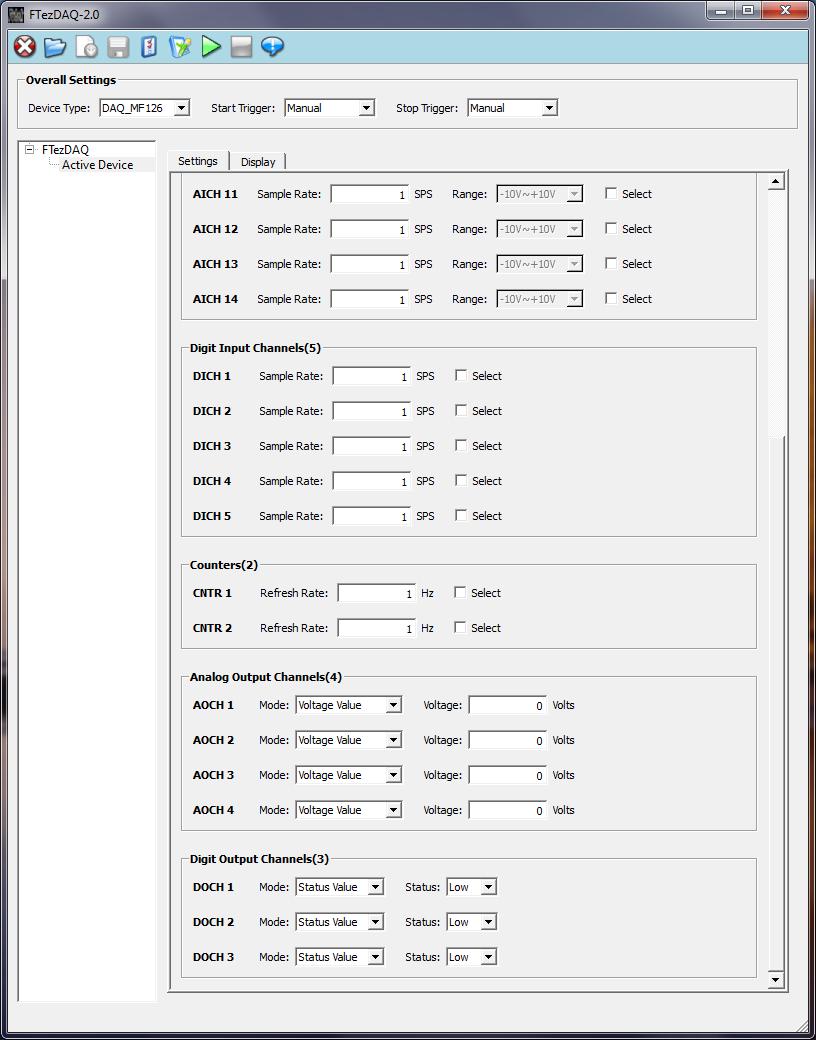
26 Model MF-126 Specifications: Analog Inputs: 14 A1 to A14 Input Voltage Range: 0 to10v Input Impedance: 400KΩ ADC Bits: 12 Digital Output: 3 D6(DOCH1), D8(DOCH2), D9(DOCH3) Digital Input: 5 D1(DICH1), D2(DICH2), D3(DICH3), D4(DICH4), D5(DICH5) Max Data Sampling Rate: 31K samples/second PWM Output: 3 o D6(DOCH1) Max Frequency 1MHz, o D8(DOCH2) Max Frequency 1KHz, o D9(DOCH3) Max Frequency 1MHz, 32 bits Counter: 2 Max Frequency 66KHz, Falling Edge Count o Counter1: D7 (CNTR1) o Counter2: D10 (CNTR2) Timer: 1 Input from D1 Analog Output: 4 12bit DAC, Range 0 to 2.5V. VOUT1 to VOUT4 o Output Waveform: Max Frequency 1KHz; fixed amplitude 2.5V. Sin Triangle Sawtooth o User Set Voltage, Range 0 to 2.5V. The FTezDAQ-2.0 window 26
27 27
DT 9818 Waveform-Generator. Hardware Trigger Version. Operating Manual. Version 2.0. May Page 1 of 21
 DT 9818 Waveform-Generator Hardware Trigger Version Operating Manual Version 2.0 May 2011 Page 1 of 21 Table of Contents 1 Components... 3 1.1 USB DAQ module DT 9818-16SE-BNC... 3 1.2 DT 9818 Waveform-Generator-CD...
UCE-DSO212 DIGITAL OSCILLOSCOPE USER MANUAL. UCORE ELECTRONICS
 UCE-DSO212 DIGITAL OSCILLOSCOPE USER MANUAL UCORE ELECTRONICS www.ucore-electronics.com 2017 Contents 1. Introduction... 2 2. Turn on or turn off... 3 3. Oscilloscope Mode... 4 3.1. Display Description...
Lab 12 Laboratory 12 Data Acquisition Required Special Equipment: 12.1 Objectives 12.2 Introduction 12.3 A/D basics
 Laboratory 12 Data Acquisition Required Special Equipment: Computer with LabView Software National Instruments USB 6009 Data Acquisition Card 12.1 Objectives This lab demonstrates the basic principals
USB-TEMP and TC Series USB-Based Temperature Measurement Devices
 USB-Based Temperature Measurement Devices Features Temperature and voltage measurement USB devices Thermocouple, RTD, thermistor, or semiconductor sensor measurements Eight analog inputs Up to ±10 V inputs*
UCE-DSO210 DIGITAL OSCILLOSCOPE USER MANUAL. FATIH GENÇ UCORE ELECTRONICS REV1
 UCE-DSO210 DIGITAL OSCILLOSCOPE USER MANUAL FATIH GENÇ UCORE ELECTRONICS www.ucore-electronics.com 2017 - REV1 Contents 1. Introduction... 2 2. Turn on or turn off... 3 3. Oscilloscope Mode... 3 3.1. Display
User s Guide. DDS-3005 USB Operation Manual
 User s Guide DDS-3005 USB Operation Manual Table of Contents Chapter 1 Introduction...1 1.1 Introduction...1 1.2 Working Principle...1 1.3 Hardware Specification...1 Chapter 2 Installation...3 2.1 System
Graphical Control Panel User Manual
 Graphical Control Panel User Manual DS-MPE-DAQ0804 PCIe Minicard Data Acquisition Module For Universal Driver Version 7.0.0 and later Revision A.0 March 2015 Revision Date Comment A.0 3/18/2015 Initial
PC-based controller for Mechatronics System
 Course Code: MDP 454, Course Name:, Second Semester 2014 PC-based controller for Mechatronics System Mechanical System PC Controller Controller in the Mechatronics System Configuration Actuators Power
ESE 350 Microcontroller Laboratory Lab 5: Sensor-Actuator Lab
 ESE 350 Microcontroller Laboratory Lab 5: Sensor-Actuator Lab The purpose of this lab is to learn about sensors and use the ADC module to digitize the sensor signals. You will use the digitized signals
ArbStudio Arbitrary Waveform Generators
 ArbStudio Arbitrary Waveform Generators Key Features Outstanding performance with 16-bit, 1 GS/s sample rate and 2 Mpts/Ch 2 and 4 channel models Digital pattern generator PWM mode Sweep and burst modes
DDS-3005 USB Arbitrary Waveform Generator and. Frequency Counter. Operation Manual V1.9
 DDS-3005 USB ManualV1.9 1 DDS-3005 USB Arbitrary Waveform Generator and Frequency Counter Operation Manual V1.9 Introduction 1.1 Introduction DDS-3005 USB Arbitrary Waveform Generator has one channel of
USB Multifunction Arbitrary Waveform Generator AWG2300. User Guide
 USB Multifunction Arbitrary Waveform Generator AWG2300 User Guide Contents Safety information... 3 About this guide... 4 AWG2300 specifications... 5 Chapter 1. Product introduction 1 1. Package contents......
Getting started with Mobile Studio.
 Getting started with Mobile Studio. IMPORTANT!!! DO NOT PLUG THE MOBILE STUDIO BOARD INTO THE USB PORT YET. First Lab: For the first lab experiment you will essentially play with the Mobile Studio Board
LV-Link 3.0 Software Interface for LabVIEW
 LV-Link 3.0 Software Interface for LabVIEW LV-Link Software Interface for LabVIEW LV-Link is a library of VIs (Virtual Instruments) that enable LabVIEW programmers to access the data acquisition features
ArbStudio Arbitrary Waveform Generators. Powerful, Versatile Waveform Creation
 ArbStudio Arbitrary Waveform Generators Powerful, Versatile Waveform Creation UNMATCHED WAVEFORM UNMATCHED WAVEFORM GENERATION GENERATION Key Features 125 MHz bandwidth 1 GS/s maximum sample rate Long
Multiple Instrument Station Module
 Multiple Instrument Station Module Digital Storage Oscilloscope Vertical Channels Sampling rate Bandwidth Coupling Input impedance Vertical sensitivity Vertical resolution Max. input voltage Horizontal
Burst mode - This is incorporated to simulate simultaneous analog input. Compatible with a range of Application Development Environments
 Agilent U2300A Series USB Modular Multifunction Data Acquisition(DAQ) Devices Data Sheet Features Up to 3 MSa/s sampling rate for a single channel Functions as a standalone or modular unit Easy to use
How to make a list sweep measurement
 How to make a list sweep measurement This material shows how to perform a list sweep measurement through an example of the Photovoltaic Cell IV measurement. Figure 1 illustrates the connection and condition
Magnitude and Phase Measurements. Analog Discovery
 Magnitude and Phase Measurements Analog Discovery Set up the oscilloscope to measure the signal of the reference voltage (the input voltage from the arbitrary function generator, in this case) and the
LAB #3: Virtual Instruments; Behavior of Second-Order Systems
 LAB #3: Virtual Instruments; Behavior of Second-Order Systems Equipment: Dell Optiplex Gs+ Pentium computer National Instruments BNC-2140 signal connector box, PCI-4451 dynamic signal acquisition board,
CHAPTER 7 HARDWARE IMPLEMENTATION
 168 CHAPTER 7 HARDWARE IMPLEMENTATION 7.1 OVERVIEW In the previous chapters discussed about the design and simulation of Discrete controller for ZVS Buck, Interleaved Boost, Buck-Boost, Double Frequency
ISDS210A ISDS210B. Multi VirAnalyzer. InstruStar Electronic Technology
 Multi VirAnalyzer ISDS210A(B) Model User Guide 2013-8-1 1 contents ISDS210A 1.Introduction Introduction 1 2.Feature Description 1 3.Software Installation 3 3. 1 Insta lla t io n pac kag e 3 3.2 Hardware
USB-PWM10. User s Manual
 USB-PWM10 User s Manual Windows, Windows2000, Windows NT and Windows XP are trademarks of Microsoft. We acknowledge that the trademarks or service names of all other organizations mentioned in this document
Auntie Spark s Guide to creating a Data Collection VI
 Auntie Spark s Guide to creating a Data Collection VI Suppose you wanted to gather data from an experiment. How would you create a VI to do so? For sophisticated data collection and experimental control,
User s Manual. Hantek1025G ARBITRARY FUNCTION GENERATOR
 User s Manual Hantek1025G ARBITRARY FUNCTION GENERATOR www.hantek.com Content General safety summary... 1 Introduction... 2 Chapter 1 Getting started... 3 1.1 System Requirements... 4 1.2 Installing Hardware...
EE 1210 Op Amps, Gain, and Signal Integrity Laboratory Project 6
 Objective Information The purposes of this laboratory project are for the student to observe an inverting operational amplifier circuit, to demonstrate how the resistors in an operational amplifier circuit
Enhancing Analog Signal Generation by Digital Channel Using Pulse-Width Modulation
 Enhancing Analog Signal Generation by Digital Channel Using Pulse-Width Modulation Angelo Zucchetti Advantest angelo.zucchetti@advantest.com Introduction Presented in this article is a technique for generating
MAX11300PMB1 Peripheral Module and Munich (USB2PMB1) Adapter Board Quick Start Guide
 Adapter Board Quick Start Guide") MAX11300PMB1 Peripheral Module and Munich (USB2PMB1) Adapter Board Quick Start Guide Rev 0; 7/14 For pricing, delivery, and ordering information, please contact Maxim Direct at 1-888-629-4642, or visit
MAX11300PMB1 Peripheral Module and Munich (USB2PMB1) Adapter Board Quick Start Guide Rev 0; 7/14 For pricing, delivery, and ordering information, please contact Maxim Direct at 1-888-629-4642, or visit
BIO 365L Neurobiology Laboratory. Training Exercise 1: Introduction to the Computer Software: DataPro
 BIO 365L Neurobiology Laboratory Training Exercise 1: Introduction to the Computer Software: DataPro 1. Don t Panic. When you run DataPro, you will see a large number of windows, buttons, and boxes. In
GENERATION OF SIGNALS USING LABVIEW FOR MAGNETIC COILS WITH POWER AMPLIFIERS
 GENERATION OF SIGNALS USING LABVIEW FOR MAGNETIC COILS WITH POWER AMPLIFIERS Ashmi G V 1, Meena M S 2 1 ER&DCI-IT, Centre for Development of Advanced Computing, Thiruvananthapuram(India) 2 LAMP Group,
EECS 216 Winter 2008 Lab 2: FM Detector Part II: In-Lab & Post-Lab Assignment
 EECS 216 Winter 2008 Lab 2: Part II: In-Lab & Post-Lab Assignment c Kim Winick 2008 1 Background DIGITAL vs. ANALOG communication. Over the past fifty years, there has been a transition from analog to
Agilent 33522A Function Arbitrary Waveform Generator. Tektronix TDS 3012B Oscilloscope
 Agilent 33522A Function/Arbitrary Waveform Generator and Tektronix TDS 3012B Oscilloscope Agilent 33522A Function Arbitrary Waveform Generator The signal source for this lab is the Agilent 33522A Function
9063-RC Data Acquisition and Control Interface
 9063-RC Data Acquisition and Control Interface LabVolt Series Datasheet Festo Didactic en 230 V - 50 Hz 11/2017 Table of Contents General Description 2 LVDAC-EMS 2 Metering 3 Oscilloscope 3 Phasor Analyzer
1.5k. (a) Resistive Circuit (b) Capacitive Circuit
 Resistive Circuit (b) Capacitive Circuit") Objective Information The purposes of this laboratory project are to become further acquainted with the use of an oscilloscope, and to observe the behavior of resistor and resistor capacitor circuits.
Objective Information The purposes of this laboratory project are to become further acquainted with the use of an oscilloscope, and to observe the behavior of resistor and resistor capacitor circuits.
Dual Channel Function/Arbitrary Waveform Generators 4050 Series
 Data Sheet Dual Channel Function/Arbitrary Waveform Generators The Dual Channel Function/Arbitrary Waveform Generators are capable of generating stable and precise sine, square, triangle, pulse, and arbitrary
Training Schedule. Robotic System Design using Arduino Platform
 Training Schedule Robotic System Design using Arduino Platform Session - 1 Embedded System Design Basics : Scope : To introduce Embedded Systems hardware design fundamentals to students. Processor Selection
MINIMUM SYSTEM REQUIREMENTS
 Quick Start Guide Copyright 2000-2012 Frontline Test Equipment, Inc. All rights reserved. You may not reproduce, transmit, or store on magnetic media any part of this publication in any way without prior
1. Hand Calculations (in a manner suitable for submission) For the circuit in Fig. 1 with f = 7.2 khz and a source vin () t 1.
 For the circuit in Fig. 1 with f = 7.2 khz and a source vin () t 1.") Objectives The purpose of this laboratory project is to introduce to equipment, measurement techniques, and simulations commonly used in AC circuit analysis. In this laboratory session, each student will:
Objectives The purpose of this laboratory project is to introduce to equipment, measurement techniques, and simulations commonly used in AC circuit analysis. In this laboratory session, each student will:
Veterinary Digital X-Ray System Quick Start Guide
 1 Veterinary Digital X-Ray System Quick Start Guide 2 SOPIX² X-Ray Sensors Quick Start Guide ***PERFORM THIS STEP BEFORE PLUGGING IN THE SENSOR*** Step 1 Load the CD: If you have already plugged in the
Ethernet-Based Temperature, Voltage and Strain Measurement Modules
 Ethernet-Based Temperature, Voltage and Strain Measurement Modules OMB-NET6000 Series OMB-NET6220 shown smaller than actual size. U 12 Analog Inputs U 8 Digital I/O U Simultaneous Sampling U Multiple Trigger
Experiment 9 The Oscilloscope and Function Generator
 Experiment 9 The Oscilloscope and Function Generator Introduction The oscilloscope is one of the most important electronic instruments available for making circuit measurements. It displays a curve plot
Analog Discovery Arbitrary Function Generator for Windows 7 by Mr. David Fritz and Ms. Ellen Robertson
 Analog Discovery Arbitrary Function Generator for Windows 7 by Mr. David Fritz and Ms. Ellen Robertson Financial support to develop this tutorial was provided by the Bradley Department of Electrical and
PSM Soft. Features and Functions January PC Software Guide. Getting connected and Communication
 PSM Soft PC Software Guide Features and Functions January 2010 The PSM series Phase Sensitive Multimeters provide a wide range of exceptionally accurate and versatile instrumentation in one unique package.
Advanced Lab LAB 6: Signal Acquisition & Spectrum Analysis Using VirtualBench DSA Equipment: Objectives:
 Advanced Lab LAB 6: Signal Acquisition & Spectrum Analysis Using VirtualBench DSA Equipment: Pentium PC with National Instruments PCI-MIO-16E-4 data-acquisition board (12-bit resolution; software-controlled
Dual Channel Function/Arbitrary Waveform Generators 4050 Series
 Data Sheet Dual Channel Function/Arbitrary Waveform Generators The Dual Channel Function/Arbitrary Waveform Generators are capable of generating stable and precise sine, square, triangle, pulse, and arbitrary
USB Line Camera 8M. Coptonix GmbH
 USB Line Camera 8M Coptonix GmbH Luxemburger Str. 31 D 13353 Berlin Phone: +49 (0)30 61 74 12 48 Fax: +49 (0)30 61 74 12 47 www.coptonix.com support@coptonix.com 2 The USB Line Camera 8M is an easy to
Understanding the Arduino to LabVIEW Interface
 E-122 Design II Understanding the Arduino to LabVIEW Interface Overview The Arduino microcontroller introduced in Design I will be used as a LabVIEW data acquisition (DAQ) device/controller for Experiments
WaveStation Function/Arbitrary Waveform Generators
 WaveStation Function/Arbitrary Waveform Generators Key Features High performance with 14-bit, 125 MS/s and 16 kpts 2 channels on all models Large 3.5 color display for easy waveform preview Over 40 built-in
Dual Channel Function/Arbitrary Waveform Generators 4050B Series
 Data Sheet Dual Channel Function/Arbitrary Waveform Generators The Dual Channel Function/ Arbitrary Waveform Generators are capable of generating stable and precise sine, square, triangle, pulse, and arbitrary
WaveStation Function/Arbitrary Waveform Generators
 Function/Arbitrary Waveform Generators Key Features High performance with 14-bit waveform generation, up to 500 MS/s sample rate and up to 512 kpts memory 2 channels on all models Large color display for
Experiment 8: An AC Circuit
 Experiment 8: An AC Circuit PART ONE: AC Voltages. Set up this circuit. Use R = 500 Ω, L = 5.0 mh and C =.01 μf. A signal generator built into the interface provides the emf to run the circuit from Output
FY10xx(S) series Direct Digital Synthesis (DDS) Signal Generator Users Manual Rev
 series Direct Digital Synthesis (DDS) Signal Generator Users Manual Rev") FY10xx(S) series Direct Digital Synthesis (DDS) Signal Generator Users Manual Rev2.3 2011-5-10 Introduction of the instrument FY10xx(FY10xxS) series direct digital synthesis signal generator use DDS technology
FY10xx(S) series Direct Digital Synthesis (DDS) Signal Generator Users Manual Rev2.3 2011-5-10 Introduction of the instrument FY10xx(FY10xxS) series direct digital synthesis signal generator use DDS technology
1. R-2R ladder Digital-Analog Converters (DAC). Connect the DAC boards (2 channels) and Nexys 4 board according to Fig. 1.
. Connect the DAC boards (2 channels) and Nexys 4 board according to Fig. 1.") Analog-Digital and Digital-Analog Converters Digital Electronics Labolatory Ernest Jamro, Maciej Wielgosz, Piotr Rzeszut Dep. of Electronics, AGH-UST, Kraków Poland, 2015-01-10 1. R-2R ladder Digital-Analog
Analog-Digital and Digital-Analog Converters Digital Electronics Labolatory Ernest Jamro, Maciej Wielgosz, Piotr Rzeszut Dep. of Electronics, AGH-UST, Kraków Poland, 2015-01-10 1. R-2R ladder Digital-Analog
Page 1/10 Digilent Analog Discovery (DAD) Tutorial 6-Aug-15. Figure 2: DAD pin configuration
 Tutorial 6-Aug-15. Figure 2: DAD pin configuration") Page 1/10 Digilent Analog Discovery (DAD) Tutorial 6-Aug-15 INTRODUCTION The Diligent Analog Discovery (DAD) allows you to design and test both analog and digital circuits. It can produce, measure and
Page 1/10 Digilent Analog Discovery (DAD) Tutorial 6-Aug-15 INTRODUCTION The Diligent Analog Discovery (DAD) allows you to design and test both analog and digital circuits. It can produce, measure and
UDB12x. 2xxS. xs seriers. Signal Generator. Manual. Users
 UDB12x 2xxS xs seriers Direct Digital Synthesis (DDS) Signal Generator Users Manual Introduction of the instrument This series direct digital synthesis signal generator use DDS technology and FPGA design
Agilent U2300A Series USB Modular Multifunction Data-Acquisition Devices
 99 Washington Street Melrose, MA 02176 Phone 781-665-1400 Toll Free 1-800-517-8431 Visit us at www.testequipmentdepot.com Back to the Agilent U2356A Product Page Agilent U2300A Series USB Modular Multifunction
Module: Arduino as Signal Generator
 Name/NetID: Teammate/NetID: Module: Laboratory Outline In our continuing quest to access the development and debugging capabilities of the equipment on your bench at home Arduino/RedBoard as signal generator.
MULT SWP X1K K VERN START FREQ DURATION AMPLITUDE 0 TTL OUT RAMP
 Signal Generators This document is a quick reference guide to the operation of the signal generators available in the laboratories. Major functions will be covered, but some features such as their sweep
USB4. Encoder Data Acquisition USB Device Page 1 of 8. Description. Features
 USB4 Page 1 of 8 The USB4 is a data acquisition device designed to record data from 4 incremental encoders, 8 digital inputs and 4 analog input channels. In addition, the USB4 provides 8 digital outputs
USB-B1 User Manual V1.1
 USB-B1 User Manual V1.1 Table of Contents 1 Introduction... 2 1.1 Device Overview... 2 1.2 System Overview... 3 1.3 Connectors... 4 1.3.1 USB Connector J11... 4 1.3.2 External Antenna Connector (J10)...
Analog Arts AG900 AG885 AG875 AG815 Product Specifications
 www.analogarts.com Analog Arts AG900 AG885 AG875 AG815 Product Specifications Arbitrary Waveform Generator General ( Typical ) Specifications AG900 AG885 AG875 AG815 Arbitrary waveform length 2 to 64K
APPENDIX E: IWX214 HARDWARE MANUAL
 APPENDIX E: IWX214 HARDWARE MANUAL Overview The iworx/214 hardware in combination with LabScribe recording software provides a system that allows coordinated control of both analog inputs and outputs.
P08050 Testing Strategy Document
 P85 Testing Strategy Document IFCN standards 1 for digital recording of clinical EEG Verification 2 3 Square-Wave Calibration Test Summary: Square-wave signals must be recorded at the beginning, using
ECE 2274 Lab 1 (Intro)
") ECE 2274 Lab 1 (Intro) Richard Dumene: Spring 2018 Revised: Richard Cooper: Spring 2018 Forward (DO NOT TURN IN) The purpose of this lab course is to familiarize you with high-end lab equipment, and train
ECE 2274 Lab 1 (Intro) Richard Dumene: Spring 2018 Revised: Richard Cooper: Spring 2018 Forward (DO NOT TURN IN) The purpose of this lab course is to familiarize you with high-end lab equipment, and train
Chapter 7. Introduction. Analog Signal and Discrete Time Series. Sampling, Digital Devices, and Data Acquisition
 Chapter 7 Sampling, Digital Devices, and Data Acquisition Material from Theory and Design for Mechanical Measurements; Figliola, Third Edition Introduction Integrating analog electrical transducers with
Analog Arts SL987 SL957 SL937 SL917 Product Specifications [1]
![Analog Arts SL987 SL957 SL937 SL917 Product Specifications [1]](/thumbs/95/126095980.jpg "Analog Arts SL987 SL957 SL937 SL917 Product Specifications [1]") www.analogarts.com Analog Arts SL987 SL957 SL937 SL917 Product Specifications [1] 1. These models include: an oscilloscope, a spectrum analyzer, a data recorder, a frequency & phase meter, an arbitrary
www.analogarts.com Analog Arts SL987 SL957 SL937 SL917 Product Specifications [1] 1. These models include: an oscilloscope, a spectrum analyzer, a data recorder, a frequency & phase meter, an arbitrary
Exercise 2-1. PAM Signals EXERCISE OBJECTIVE DISCUSSION OUTLINE. Signal sampling DISCUSSION
 Exercise 2-1 PAM Signals EXERCISE OBJECTIVE When you have completed this exercise, you will be familiar with the generation of both natural and flat-top sampled PAM signals. You will verify how the frequency
DC and AC Circuits. Objective. Theory. 1. Direct Current (DC) R-C Circuit
 R-C Circuit") [International Campus Lab] Objective Determine the behavior of resistors, capacitors, and inductors in DC and AC circuits. Theory ----------------------------- Reference -------------------------- Young
[International Campus Lab] Objective Determine the behavior of resistors, capacitors, and inductors in DC and AC circuits. Theory ----------------------------- Reference -------------------------- Young
YCE13. Dealer PC Programming Software Reference Manual. Attention!
 YCE13 Dealer PC Programming Software Reference Manual Attention! The YCE13 programing software can only be used with HX380/400 firmware version Ver. 2.00 or later. This software is used to program the
Agilent Technologies 3000 Series Oscilloscopes
 Agilent Technologies 3000 Series Oscilloscopes Data Sheet Full-featured oscilloscopes for the smallest budgets Features: 60 to 200 MHz bandwidths 1 GSa/s maximum sample rate Large 15-cm (5.7-in) color
Design and Fabrication of High Frequency Linear Function Generator with Digital Frequency Counter using MAX038 and a PIC microcontroller
 International Journal of Latest Tr ends in Engineering and Technology Vol.(7)Issue(3), pp. 263-270 DOI: http://dx.doi.org/10.21172/1.73.536 e-issn:2278-621x Design and Fabrication of High Frequency Linear
WaveStation Function/Arbitrary Waveform Generators
 WaveStation Function/Arbitrary Waveform Generators Key Features High performance with 14-bit, 125 MS/s and 16 kpts 2 channels on all models Large 3.5 color display for easy waveform preview Over 40 built-in
Lab 3: AC Low pass filters (version 1.3)
") Lab 3: AC Low pass filters (version 1.3) WARNING: Use electrical test equipment with care! Always double-check connections before applying power. Look for short circuits, which can quickly destroy expensive
Lab 3: AC Low pass filters (version 1.3) WARNING: Use electrical test equipment with care! Always double-check connections before applying power. Look for short circuits, which can quickly destroy expensive
Creating Arbitrary Waveforms in the U2300A Series and U2500A Series Data Acquisition Devices
 Creating Arbitrary Waveforms in the U2300A Series and U2500A Series Data Acquisition Devices Application Note Introduction The U2300A Series and U2500A Series data acquisition device (DAQ) families are
Analog Arts SF990 SF880 SF830 Product Specifications
 1 www.analogarts.com Analog Arts SF990 SF880 SF830 Product Specifications Analog Arts reserves the right to change, modify, add or delete portions of any one of its specifications at any time, without
Tutorial #5: Emitter Follower or Common Collector Amplifier Circuit
 Tutorial #5: Emitter Follower or Common Collector Amplifier Circuit This tutorial will help you to build and simulate a more complex circuit: an emitter follower. The emitter follower or common collector
LV8716QAGEVK Evaluation Kit User Guide
 LV8716QAGEVK Evaluation Kit User Guide NOTICE TO CUSTOMERS The LV8716QA Evaluation Kit is intended to be used for ENGINEERING DEVELOPMENT, DEMONSTRATION OR EVALUATION PURPOSES ONLY and is not considered
Output Impedance. Duty Cycle Range. Buffer Size Resolution. PROTECTION Input Over Voltage. Output Short Circuit. TRIGGERING Sources.
 3 Channel Digital Storage Oscilloscope (DSO) Instrument VERTICAL SPECIFICATIONS Analogue Bandwidth (-3dB) Bandwidth Limiting Rise time (10% to 90%, calculated) Input ranges (full scale) Input sensitivity
Instruction Manual for the Software of ASSAN V2 Series Receiver
 Instruction Manual for the Software of ASSAN V2 Series Receiver I. Setup 1. Double click SETUP to enter the welcome interface and click Next. 2. Enter your name and company name and click Next. 3. Select
FD 5 / 10 / 15. Fast acquisition module with universal synchronized inputs and embedded webserver software
 Fast acquisition module with universal synchronized inputs and embedded webserver software FD systems are a series of fast (470 Hz/channel) and flexible data acquisition modules available in 3 models of
DT9838 Strain Measurement Module
 Strain- and Bridge-Based Measurement Module Strain Measurement Module The module is a strain gage measurement device intended for full-, half, and quarter-bridge strain gage elements and bridge-based sensor
Exercise 2: Demodulation (Quadrature Detector)
") Analog Communications Angle Modulation and Demodulation Exercise 2: Demodulation (Quadrature Detector) EXERCISE OBJECTIVE When you have completed this exercise, you will be able to explain demodulation
Analog Communications Angle Modulation and Demodulation Exercise 2: Demodulation (Quadrature Detector) EXERCISE OBJECTIVE When you have completed this exercise, you will be able to explain demodulation
MBC DG GUI MBC INTERFACE
 MBC DG GUI MBC INTERFACE User Manual Version 2.6 Table des matières Interface - Introduction... 3 Interface - Setup... 3 Minimum Computer Requirements... 3 Software installation... 3 Hardware Setup...
Analog Arts SG985 SG884 SG834 SG814 Product Specifications [1]
![Analog Arts SG985 SG884 SG834 SG814 Product Specifications [1]](/thumbs/94/122371203.jpg "Analog Arts SG985 SG884 SG834 SG814 Product Specifications [1]") www.analogarts.com Analog Arts SG985 SG884 SG834 SG814 Product Specifications [1] 1. These models include: an oscilloscope, a spectrum analyzer, a data recorder, a frequency & phase meter, and an arbitrary
www.analogarts.com Analog Arts SG985 SG884 SG834 SG814 Product Specifications [1] 1. These models include: an oscilloscope, a spectrum analyzer, a data recorder, a frequency & phase meter, and an arbitrary
Model and
 Function Generator Model 72-14110 and 72-14111 0 Contents Function Generator... 0 Model 72-14110 and 72-14111... 0 Chapter 1 Safety Information... 3 1.1 Safety Terms and Symbols... 3 1.2 General Safety
Function Generator Guide Tektronix AFG3102
 Tektronix AFG3102 ersion 2008-Jan-1 Dept. of Electrical & Computer Engineering Portland State University Copyright 2008 Portland State University 1 Basic Information This guide provides basic instructions
Data Sheet. Digital Storage Oscilloscope. Features & Benefits. Applications. Ease-of-Use Feature DSO5202BMT DSO5102BMT DSO5062BMT
 Data Sheet Digital Storage Oscilloscope DSO5202BMT DSO5102BMT DSO5062BMT Features & Benefits 200/100/60MHz Bandwidths 1GSa/s Real Time Sample Rate 2M Memory Depth Trigger mode: Edge, Pulse Width, Video,
ME-5265 Isolated 16 bit/2 MS/s DAQ Board
 ME-5265 Isolated 16 bit/2 MS/s DAQ Board Fast Highly reliable Full-differential analog channels with full isolation The ME-5265 is a fast, highprecision analog DAQ board with 4 or 8 isolated, differential
Supplementary User Manual for BSWA Impedance Tube Measurement Systems
 Supplementary User Manual for BSWA Impedance Tube Measurement Systems 1 P age Contents Software Installation... 3 Absorption Measurements -- ASTM Method... 4 Hardware Set-Up... 4 Sound card Settings...
ni.com Sensor Measurement Fundamentals Series
 Sensor Measurement Fundamentals Series Introduction to Data Acquisition Basics and Terminology Litkei Márton District Sales Manager National Instruments What Is Data Acquisition (DAQ)? 3 Why Measure? Engineers
AF10 PWM Generator. Manual. Valid as of firmware version v1.4.1
 AF10 PWM Generator Manual Valid as of firmware version v1.4.1 1 AF10 PWM Generator Manual Contents 1 Controls... 4 1.1 Main switch (back)... 4 1.2 ON button... 4 1.3 Esc button... 4 1.4 Setup button...
LABORATORY 3: Transient circuits, RC, RL step responses, 2 nd Order Circuits
 LABORATORY 3: Transient circuits, RC, RL step responses, nd Order Circuits Note: If your partner is no longer in the class, please talk to the instructor. Material covered: RC circuits Integrators Differentiators
THE DEVELOPMENT OF AN INTEGRATED GRAPHICAL SLS PROCESS CONTROL INTERFACE
 THE DEVELOPMENT OF AN INTEGRATED GRAPHICAL SLS PROCESS CONTROL INTERFACE ABSTRACT Guohua Ma and Richard H. Crawford The University of Texas at Austin This paper presents the systematic development of a
Quick Start RSDG2000X Function/Arbitrary Waveform Generator
 Quick Start RSDG2000X Function/Arbitrary Waveform Generator 1 2 General Safety Summary Carefully read the following safety precautions to avoid any personal injuries or damages to the instrument and any
II. LAB. * Open the LabVIEW program (Start > All Programs > National Instruments > LabVIEW 2012 > LabVIEW 2012)
") II. LAB Software Required: NI LabVIEW 2012, NI LabVIEW 4.3 Modulation Toolkit. Functions and VI (Virtual Instrument) from the LabVIEW software to be used in this lab: niusrp Open Tx Session (VI), niusrp
II. LAB Software Required: NI LabVIEW 2012, NI LabVIEW 4.3 Modulation Toolkit. Functions and VI (Virtual Instrument) from the LabVIEW software to be used in this lab: niusrp Open Tx Session (VI), niusrp
OBJECTIVE The purpose of this exercise is to design and build a pulse generator.
 ELEC 4 Experiment 8 Pulse Generators OBJECTIVE The purpose of this exercise is to design and build a pulse generator. EQUIPMENT AND PARTS REQUIRED Protoboard LM555 Timer, AR resistors, rated 5%, /4 W,
PWM P108. Programming Instructions v 3.2 PWM Controller Software
 PWM P108 Programming Instructions v 3.2 PWM Controller Software PWM P108 Programming Instructions v 3.2 for PWM Controller Software Download / Install & Run Driver (Must be installed for software to work)
MICROCONTROLLER TUTORIAL II TIMERS
 MICROCONTROLLER TUTORIAL II TIMERS WHAT IS A TIMER? We use timers every day - the simplest one can be found on your wrist A simple clock will time the seconds, minutes and hours elapsed in a given day
Agilent U2300A Series USB Modular Multifunction Data Acquisition Devices. Data Sheet
 Agilent U2300A Series USB Modular Multifunction Data Acquisition Devices Data Sheet Features Up to 3 MSa/s sampling rate for a single channel Functions as a standalone or modular unit Easy to use plug-andplay
Tektronix Courseware. Academic Labs. Sample Labs from Popular Electrical and Electronics Engineering Curriculum
 Tektronix Courseware Academic Labs Sample Labs from Popular Electrical and Electronics Engineering Curriculum March 3, 2014 HalfWaveRectifier -- Overview OBJECTIVES After performing this lab exercise,