H 2 S CO CH 4. Detective Net User & Operator Manual. Detective Net
|
|
|
- Roderick Stevenson
- 5 years ago
- Views:
Transcription


1 H 2 S CO CH 4 Detectve Net User & Operator Manual Detectve Net M070019/ENG Issue 3 Aug 2015
.")
2 NAVIGATION INSTRUCTIONS The symbols n the left-hand margn of each page of the manual wll enable you to carry out the followng functons: Contents Clck on ths button to dsplay the Contents page. Clck on ths button to dsplay the prevous page. Clck on ths button to dsplay the next page. Clck on ths button to dsplay the prevous vew (use t to return from a reference jump). Clck on ths button to dsplay next vew (use t to return to a reference jump). Clck ths button to prnt some or all of the document (specfc pages can be chosen). Ext Clck ths button to ext the user gude.! Press the Esc key to dsplay normal Acrobat! Controls.
3 CONTENTS Functonal Overvew...5 Safety Informaton...6 Glossary Operaton In the box Box contents Devce detals Connecton to Detectve LED ndcatons LED1 - Power/Learn Mode (Red LED) LED2 Network Status (Red/Amber/Green LED) LED3 - Alarms (Red LED) LED4 Master/Slave (Green LED) Battery Indcaton LED (Red LED) LED repetton rates Functon buttons Functon Button 1 (FB1) Functon Button 2 (FB2) Functon Button 1 (FB1) & Functon Button 2 (FB2) System Confguraton Swtchng on a devce Resettng a devce Toggle Devces between Master & Slave Functonalty Settng Up a Smple Wreless Network Network connecton test Addng addtonal slave devces to the network Removng Slave Devces from the Network Power Down master or slave devce Powerng Up a Prevously confgured network
4 1.7 Network Deployment Deployment Process Force Communcaton Network Topology Alarms and Alerts Gas alarm Network Alert Modulated Alert Network Operaton Normal Operaton Loss of Connecton to Wreless Network Re-establshng Network Connecton Detectve Net Devce - Low Battery Alert Detectve+ - Power Down or Inadvertent Swtch Off Internal Fault Detectve Net specfcaton Servce and mantenance Troubleshootng Accessores RICOCHET Mesh Technology...37 Warranty...38 Crowcon contacts
5 Functonal Overvew Ths manual should be read n conjuncton wth the Detectve+ user manual. Detectve Net s a cable replacement wreless soluton for Detectve or Detectve+ allowng wreless transmsson of gas alarm events between devces. A gas alarm event on a Detectve+ shall cause an alert to be transmtted to all other Detectve Net devces on the network whch n turn wll cause all Detectve+ unts n the network to go nto alert. Ths wll ensure that all personnel beng protected by the network are alerted to a gas event that may be remote from ther current locaton. Detectve Net s smply connected to the exstng nterconnectng cable connector and s suppled wth a clp for mountng. A Detectve Net devce can be confgured as ether a master or a slave devce and a full wreless network can consst of one master devce master and up to 25 slave devces. The wreless network can be ether confgured pror to deployment or once the devces are deployed. It s also possble to add or remove further slave devces once a network s confgured and operatonal. 5
6 Safety Informaton Detectve Net s a hazardous area certfed product and as such must be operated and mantaned n strct accordance wth the nstructons, warnngs and label nformaton ncluded n ths manual. Detectve Net must be operated wthn the lmtatons stated. Ths document s applcable to Detectve Net 433 and Detectve Net 868. Read and understand all nstructons n ths manual pror to use. Before use ensure that the equpment s n good condton and that the enclosure s ntact has not been damaged n any way. If there s any damage to the equpment do not use, contact your local Crowcon offce or agent for repar/replacement There are no user replaceable nternal parts and only Crowcon or Crowcon agent servce personnel can servce ths product. Only genune Crowcon replacement parts must be used; substtute components may mpar ntrnsc safety and nvaldate safety certfcaton and warranty of Detectve Net. Detectve Net has a non-rechargeable battery that must only be changed n non-hazardous (safe) areas by Crowcon or Crowcon agent servce personnel No lve mantenance s permssble Observe all warnngs and nstructons marked on the unt and wthn ths manual. If ths product s not workng properly, read the troubleshootng gude and/or contact your local Crowcon offce or agent, for detals reference the Crowcon Contacts secton of the manual Rsk of statc dscharge. Durng nstallaton n a fxed locaton take care to avod statc generatng mechansm. Once nstalled do not touch certfcaton label on rear of devce f a flammable hazard s present. The metal connector shell has a capactance of 7 pf when measured n accordance wth IEC/ EN Installatons where the resstance to earth of ths exposed metal surface s greater than 1G Ω must consder the potental electro-statc charge rsk (e.g. n accordance wth CLC/ TR or other relevant publcatons). Detectve Net should be used wth one of the followng nterconnecton cables, Crowcon part number E070010, E & E070028, havng the followng parameters: Cmax = 15 nf/m; Lmax = 75 uh/m, Rmn = 30 mω/m. 6
7 The entty parameters of Detectve Net are: Uo = 3.7 V U = 10 V Io = 14.3 ma I = 25 ma Po = 8.7 mw P = 62.5 mw Co = 999 uf C = 240 nf Lo = 173 mh L = 0 Lo/Ro = 2.68 mh/ω When used and nstalled n accordance wth IEC/EN and IEC/EN , Detectve NET s sutable for use n Zones 0, 1, 2 for Groups IIA, IIB or IIC and Temperature Classes T1 T4 provded any devce(s) Detectve NET s connected to also provdes an approprate Level of Protecton, Group Classfcaton and Temperature Classfcaton. The followng condtons must also be met: Other Devce(s) U> 3.7 V I > 14.3 ma P > 8.7 mw C + Ccable< 999 uf L + Lcable< 173 mh Other Devce(s) Uo< 10 V Io < 25 ma Po < 62.5 mw Co >Ccable nf Lo >Lcable When Detectve NET s connected to multple other devces the system must be consdered per IEC/EN Detectve Net meets the delectrc strength requrement of clause n IEC/EN


8 Certfcaton label The certfcaton markng s as follows: Fgure 1: Certfcaton label II 1 G 1180 Ex a IIC T4 Ga Tamb: -20 C to +55 C IECEx ULD X DEMKO 13 ATEX X WARNING -- ELECTRO STATIC HAZARD. REFER TO MANUAL M07006 BEFORE USE BLACKLANDS BROOK DRIVE WAY ABINGDON MILTON BUSINESS PARK PARK OX14 4SD 1DY UNITED KINGDOM Detectve Net s certfed for use n ambent temperatures n the range -20 C to +55 C (-4 to 131 F). Applcable Standards Refer to equpment markng for confrmaton of applcable certfcaton before use. IECEx IEC th Edton (2011) Electrcal apparatus for explosve gas atmospheres Part 0: General requrements IEC th Edton (2012) Explosve atmospheres - Part 11: Equpment protecton by ntrnsc safety IEC nd Edton (2009) Explosve atmospheres - Part 26: Equpment wth protecton level (EPL) Ga Ex a IIC T4 Ga Tamb -20 C to +55 C IECEx ULD X 8
9 ATEX EN :2012 Electrcal apparatus for explosve gas atmospheres Part 0: General requrements EN : 2012 Explosve atmospheres - Part 11: Equpment protecton by ntrnsc safety IEC :2007 Explosve atmospheres - Part 26: Equpment wth protecton level (EPL) Ga II 1 G Ex a IIC T4 Ga Tamb -20 C to +55 C DEMKO 13 ATEX X 9
10 Glossary Ths secton detals the terms used wthn ths manual. Detectve Net Master Devce One devce n each network must be confgured to be a master devce that wll control the network and all slave devces. Detectve Net Slave Devce A network wll consst of one master devce that controls the network; all other devces wll be slave devces. Network Hoppng Network hoppng descrbes the process of the master Detectve Net devce communcatng not drectly wth a slave devce but by passng the message through another slave devce, or hoppng. Learn Mode All slave devces must be confgured to operate wth the master devce n the wreless network. Learn Mode descrbes the process of learnng a slave devce to the master devce. Slave devces must be learned to the network pror to deployment. Gas alarm A gas alarm s ntated when a Detectve+ unt detects gas and goes nto alarm wth the beacon and lghts n operaton. Network Alert A network alert s the response of the network to a gas alarm event on a Detectve+ unt wthn the network. A network alert wll cause all other Detectve+ unts wthn the network to go nto network alert mode, beacon and lghts wll flash at a slower rate than a gas alarm to dfferentate t. Force Communcaton If no wreless connecton exsts between devces, the force communcaton feature can be utlzed to re-establsh communcatons by pressng any button on a slave devce. 10
11 Modulated Alert A Modulated Alert s a response of Detectve Net to a problem wth the Detectve Net devce, for example f a slave Detectve Net devce has lost connecton to the network a modulated alert wll be sent to the locally-attached Detectve+. The wll cause Detectve+ to go nto Modulated Alert, the beacon and lghts wll flash for 3 seconds followed by a 5 second pause; ths pattern wll then be repeated. Network Connecton Test Once a network has been confgured, deployed and connected to Detectve+ unts t s possble to undertake a network connecton test to ensure all Detectve Net unts are confgured correctly and are wthn range on the network. A Network Connecton Test wll cause all devces confgured wthn the network to be placed n Network Alert for 10 seconds. RICOCHET Mesh Network Each Detectve Net devce can provde alternatve wreless transmsson routes. Should a wreless connecton between two Detectve Net devces weaken, the network automatcally re-routes communcaton va alternatve Detectve Net devce. Ths creates a mesh type network allowng a more robust and effcent wreless network. 11


 Á Functon Button")
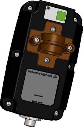
12 Contents 1. Operaton 1.1 In the box Remove the Detectve Net from the packagng and check for any vsble damage. The followng tems wll be ncluded as standard: Box contents Overvew Glossary Operaton Detectve Net Connecton cable Mountng adapter Quck start gude CD Manual The box label detals the contents. Specfcaton 1.2 Devce detals Servce and mantenance The man components of the Detectve Net are shown n Fgure 2 below: Troubleshootng Accessores Warranty Contacts Fgure 2: Devce detals  ŠÀ Functon Button 1 (FB1) Á Functon Button 2 (FB2)  Indcator LEDs à Low battery ndcator Ä Cable connector Å Detectve+ Fxed Æ Á Mount Bracket Æ Bracket securng screws À Ä Ã Ext 12


13 1.3 Connecton to Detectve Detectve Net s provded wth a standard 0.7m nterconnectng cable. If Detectve Net s requred to be placed remotely from the Detectve the standard Detectve+ 10m and 20m nterconnectng cable can be used (see Accessores table page 36). Only these cables must be used and the maxmum cable length must not exceed 20m otherwse ntrnsc safety may be mpared. Connect the Detectve Net to a Detectve+ module as shown n below: Fgure 3: Connecton 13
 Indcates that the devce s ether powered up and/or n network learn mode.")
14 1.4 LED ndcatons Detectve Net provdes four LED ndcatons (numbered 1 to 4) À to provde nformaton as to the status of the wreless devce, network, alarm or alert. There s also a battery status LED Á. Fgure 4: LEDs À Á LED1 - Power/Learn Mode (Red LED) Indcates that the devce s ether powered up and/or n network learn mode. Sngle flash Powered up n normal operaton Contnuous flash Devce n Learn Mode LED2 Network Status (Red/Amber/Green LED) Indcates the current status of the network connecton or the status result of Learn Mode. LED2 - Sngle Flash green Master Devce Network okay - all confgured slave devces connected to network Slave Devce Network okay - slave has network connecton to master devce 14
15 LED2 - Double Flash amber Master Devce No wreless communcaton to one or more confgured slaves - attemptng to re-establsh connecton Slave Devce No wreless communcaton to master - attemptng to re-establsh connecton LED2 - Long Sngle Flash Amber Master Devce Indcaton to show a slave has just been unlearnt from the network (see page 20) LED2 - Double Flash red Master Devce Network fault no wreless communcaton to one or more confgured slave devces Slave Devce Network fault no wreless communcaton to master LED2 - Trple Flash Green Master/Slave Devce Learn/Unlearn was successful or force communcatons was successful LED2 - Trple Flash Red Master/Slave Devce Learn/Unlearn was unsuccessful or force communcatons was unsuccessful LED3 - Alarms (Red LED) Indcates a Detectve Net gas alarm or a network alert. Sngle flash Gas alarm event Double flash Network alert event LED4 Master/Slave (Green LED) Indcates f the Detectve Net s confgured as a master or a slave devce. Sngle Flash green Devce confgured as Master Devce LED off Devce confgured as Slave Devce Battery Indcaton LED (Red LED) Indcates low battery status on Detectve Net devce. Sngle Flash red Low Battery LED repetton rates LED repetton flash rate on start up (.e. whlst the network s confgurng and stablsng) wll be once every 5 seconds. Once the network s stablsed the flash rate s decreased to once every 30 seconds to conserve battery lfe. 15
16 Contents 1.5 Functon buttons Detectve Net has two buttons (FB1 À and FB2 Á) that control the functonalty of the devce. Fgure 5: Functon buttons À Overvew Á Glossary Operaton Specfcaton Servce and mantenance Troubleshootng Accessores Button functonalty s as follows: Functon Button 1 (FB1) Hold down for 3 seconds (Devce off) Double clck Warranty Contacts Hold down for 3 seconds (Devce on) Powers up devce Unlearns a slave devce from a confgured network (master devce wll also need to be n learn mode to perform ths operaton) Resets a master or a slave devce Functon Button 2 (FB2) Hold down for 3 seconds (Devce on) Double clck Toggles functonalty between a master and slave devce, hold to change a master devce to a slave devce or vsa Enter/leave learn mode (slave devce wll leave learn mode automatcally) Functon Button 1 (FB1) & Functon Button 2 (FB2) Ext Hold down for less than 1 second Intates a system network connecton test Hold down for 3 seconds (Devce on) Powers down devce 16
17 1.6 System Confguraton A Detectve Net wreless network can be confgured ether before deployment of Detectve+ unts n an offce or laboratory envronment, or durng deployment of Detectve+ unts n the feld. The followng sectons detal how to setup and confgure a wreless network. Ths process need only be undertaken once, f a network of confgured and learned wreless devces s powered down, upon beng powered up agan the devces wll retan the prevous confguraton and be able to operate mmedately Swtchng on a devce Hold down FB1 for 3 seconds. The LED ndcators wll llumnate sequentally left to rght to ndcate power up. LED1, LED2 or LED4 may be llumnated dependant upon prevous confguratons these can be gnored at ths stage; the devce must now be reset Resettng a devce A reset wll cause the devce to erase any prevous network confguraton but wll not change the functon of the devce. For example f the devce was prevously a master devce t wll contnue to be so after a reset but the master wll no longer retan any slave nformaton prevously learned. It wll effectvely become a blank master devce. Wth the devce powered up, hold down FB1 for 3 seconds. If the devce was prevously confgured a slave devce, LED1 wll flash 3 tmes to ndcate a successful reset on a slave devce. LED1 wll then contnue to flash red ndcatng the devce s a slave devce. X X If the devce was prevously confgured as a master devce, LED1 wll flash green and LED4 wll flash red 3 tmes to ndcate a successful reset on a master devce. LED1 wll then contnue to flash red and LED4 wll contnue to flash green ndcatng the devce s confgured as a master devce. 17
18 1.6.3 Toggle Devces between Master & Slave Functonalty Each network requres only one master devce; all other devces should be slave devces. One unt n the network should be confgured as a master devce and all other unts should be confgured as slave devces. To toggle between master and slave functonalty press FB2 for 3 seconds. If the devce was a slave devce and s beng toggled to a master devce LED4 wll flash 3 tmes ndcatng a successful toggle from a slave to a master. LED1 wll then contnue to flash red and LED4 wll contnue to flash green ndcatng the devce s confgured as a master devce. If the devce was a master devce and s beng toggled from a master to a slave devce LED1 wll flash 3 tmes ndcatng a successful toggle from a master to slave. LED1 wll then contnue to flash red ndcatng the devce s confgured as a slave devce Settng Up a Smple Wreless Network Take a devce confgured as the master devce ensurng t has been reset (see Secton 1.6.2) and double-clck FB2 to enter learn mode. LED1 wll contnuously flash red, to ndcate devce s n the learn mode and LED4 wll contnue to flash green. Take a devce confgured as a slave devce ensurng t has been reset (see Secton 1.6.2) and place a mnmum of 1m apart from the master devce. The slave and master devces must be placed a mnmum of 1m apart to ensure correct operaton durng normal operaton and also when settng up the pared network. Double-clck FB2 on the slave devce to enter learn mode LED1 wll contnuously flash red to ndcate the devce s n learn mode. The slave devce wll learn automatcally and when complete, LED1 turns off and LED2 wll flash green to ndcate the slave s connected to the master. If the learn process s unsuccessful, the slave devce wll ndcate ths as LED2 wll flash red 3 tmes to show an unsuccessful learn and LED1 wll revert to flashng red to show powered up. The slave wll ext learn mode. If the devce had prevously been connected to a network, LED2 would revert back to ts prevous state and LED1 would reman off. X X The master devce wll ndcate a successful learn of a slave devce by a trple green flash on LED2 (ths wll only occur once) and LED1 remans contnuously flashng red, ndcatng the devce s stll n the learn mode. LED4 contnues to flash green ndcatng ts master status. 18
19 The slave devce s now confgured to the network. If requred, further slaves devces can be learnt to the network n the same manner as descrbed prevously. If no further slaves are to be added to the network double-clck FB2 button on the master devce to ext learn mode, LED4 contnues to flash green, LED2 wll flash green to show the slave s connected to the network and LED1 turns off. A network of one master and one slave devce has now been confgured for use Network connecton test Once a network has been confgured, deployed and connected to Detectve+ unts t s possble to undertake a network connecton test to ensure all Detectve Net devces are confgured correctly and are wthn range on the network. Press and hold both FB1 and FB2 on ether a master or slave devce momentarly to ntate a system connecton test. A network connecton test wll cause all devces confgured wthn the network to be placed n network alert for 10 seconds. If a confgured devce s not placed nto network alert upon ntaton of the network test, t may be out of range and must be moved closer to an adjacent devce. If a confgured devce cannot be moved closer to an adjacent devce, utlsng the 10m or 20m cable accessory t can be detached from the Detectve + mountng and elevated to mprove wreless connectvty. It s mportant to undertake a network connecton test once the network s setup and deployed. Ths ensures all devces are functonng and correctly connected to the network. 19
20 1.6.6 Addng addtonal slave devces to the network Once a network has been confgured further slaves can be added to the network at any tme: On the master devce, double-clck FB2 to enter learn mode. Take a devce confgured as a slave devce ensurng t has been reset (see Secton on page 17) swtch on and place a mnmum of 1m apart from the master devce, then double-clck FB2 to enter learn mode, LED1 wll contnuously flash red to ndcate the devce s n learn mode. The slave wll learn automatcally and when complete, LED1 turns off and LED2 changes to a sngle green flash (network OK). The master devce wll ndcate a successful learn of a slave devce by a trple green flash on LED2 (ths wll only occur once) and LED1 remans contnuously flashng red, ndcatng the devce s stll n the learn mode. LED4 contnues to flash green ndcatng ts master status. The slave s now confgured to the network. To add further slave devces repeat the above process untl all requred slaves are confgured to the network. If no further slaves are to be added to the network double-clck FB2 button on the master devce to ext learn mode, LED4 contnues to flash green, LED2 wll sngle flash green to show the slave s connected to the network and LED1 turns off. It s mportant to undertake a network connecton test f slaves are added to the network. Ths ensures all devces are functonng and correctly connected to the network Removng Slave Devces from the Network Once a network has been confgured f a slave devce s to be removed from the network as t s no longer requred, ths must be unlearned from the network to prevent the network ndcatng a fault. If a slave devce s removed from a network to whch t was prevously learned, the master wll ndcate a fault by llumnatng LED2.To prevent ths, a slave must be unlearned from the network. Take the devce confgured as the master devce and double-clck FB2 to enter learn mode. LED1 wll contnuously flash red, to ndcate devce s n the learn mode and LED4 wll contnue to flash green ndcatng master status. X X Take the slave devce to be removed from the network and double-clck FB1 to enter unlearn mode, LED1 wll flash red contnuously, to ndcate t s n unlearn mode. 20
21 The slave wll unlearn automatcally and leave the network, f the slave successfully leaves the network LED2 wll flash green 3 tmes to ndcate successful unlearn then wll be extngushed to show devce no longer on the network. LED1 flashes red to show devce s powered. If the unlearn process s unsuccessful, the slave devce wll ndcate ths as LED2 wll flash red 3 tmes to show an unsuccessful unlearn then LED2 wll revert would revert back to ts prevous state pror to the unlearn process. The slave wll ext unlearn mode and be mantaned n the network. The master devce wll ndcate successful unlearn of a slave devce by a trple green flash on LED2 (ths wll only occur once) and LED1 remans contnuously flashng red, ndcatng the devce s stll n the learn mode. LED4 contnues to flash green ndcatng ts master status. Double-clck FB2 on master devce to ext Learn mode. LED4 contnues to flash green, LED2 wll flash green to show the slave s connected to the network and LED1 turns off. It s mportant to ensure the master devce exts learn mode or the network wll not operate correctly. The slave s now removed from the network Power Down master or slave devce When the wreless network s decommssoned to preserve battery lfe the master and slave devces should be powered down. Hold down both FB1 & FB2 for 3 seconds to power down. LED s wll flash rght to left to ndcate a power down sequence Powerng Up a Prevously confgured network If a network of confgured and learned wreless devces are powered down, upon the devces beng powered up agan the devces wll remember the prevous confguraton,.e. f they were prevously confgured as a master or slave. It s not necessary to reconfgure the network. The deployment nstructons on page 22 should then be followed. 21
22 1.7 Network Deployment Correct deployment of the wreless network s mportant as t wll ensure the system operates effectvely and relably. The followng nstructons assume that the network has prevously been confgured and all requred slave devces have been learned to a master devce pror to deployment (see Secton below). However the network confguraton and master slave learn process could be undertaken durng the deployment process. The followng nstructons should always be followed when deployng the network: Deployment Process All devces should be powered down and connected to Detectve+ wth the requred nterconnectng cable (see page 13). Before deployment ensure no Detectve Net devces are ndcatng a low battery. Any devce wth the battery ndcaton LED llumnated should not be deployed and should be unlearned from the network and replaced. Pror to powerng the detectve net devce ensure the Detectve + s powered and operatng normally, or the wreless devce wll deem the Detectve + to have exhausted ts battery and wll ntate an alert on the network. The master devce should be powered frst and placed as centrally as possble n the network (ths wll make best use of the benefts of the mesh network). LED2 wll flash amber twce to ndcate no network connecton (as no slave devces are powered at ths pont) and LED4 wll flash green ndcatng ts master status. When placng the slave devces start wth the devce closest to the master and work outwards. Place the frst slave devce n poston and power up, LED2 wll double flash amber to ndcate the slave devce has no wreless communcaton to the master devce and t s attemptng to establsh connecton. The slave devce may establsh communcaton quckly and LED2 wll then flash green 3 tmes, ndcatng communcaton to the master has been establshed. LED2 wll then revert back to a green flash ndcatng establshed network connecton. If the devce does not connect then use the force communcaton process to establsh connecton (see page 23). 22
23 If network connecton s stll not establshed t may be that the devces have exceeded the connectvty range wthn that gven envronment. Reposton the slave devce deally closer to the master devce. or closer to a slave devce that has successful communcaton and repeat the force communcaton process. Repeat ths process untl communcaton s establshed. If a confgured devce cannot be moved closer to an adjacent devce, utlsng the 10m or 20m cable accessory t can be removed from Detectve + and elevated to mprove wreless connectvty. Ths process should then be repeated for all confgured slave devces workng outwards from the master devce untl the full network has establshed communcatons. At ths pont all devces n the network should ndcate a fully functonng network by flashng LED2 green. Once all Detectve Net devces have been deployed a Network Connecton test must be performed. Ths ensures all devces are functonng and correctly connected to the network. Once all Detectve Net devces have been deployed a Network Connecton test must be performed. Ths ensures all devces are functonng and correctly connected to the network. If the sequence as descrbed above s not followed when powerng up the network, dependant upon the network confguraton t may take up to an hour before the whole network s fully establshed Force Communcaton The force communcaton process can be used to force a slave devce to re-establsh communcaton to a master devce. Press any button on the slave devce and ths wll force the slave to establsh communcatons wth the master devce. LED2 wll flash amber contnuously whlst the devce attempts to re-establsh communcatons, once communcatons s re-establshed LED2 should then sngle flash green. Once communcaton to the master has been re-establshed t s mportant to repeat the network connecton test and ensure all devces respond approprately. If the force communcatons process s unsuccessful and connecton s not re-establshed, LED2 wll flash red 3 tmes to ndcate unsuccessful communcatons and then LED2 wll contnue to double flash amber ndcatng the devce s tryng to re-establsh network connecton. The force communcaton process can be repeated several tmes. If the devce s unable to re-establsh network connecton LED2 wll double flash red ndcatng network connecton s lost. 23


24 Contents If t s not possble to establsh network t may be that the devces have exceeded the connectvty range wthn that gven envronment. Reposton the slave devce deally closer to the master devce, or closer to a slave devce that has successful communcaton and repeat the force communcaton process. Repeat ths process untl communcaton s establshed. If a confgured devce cannot be moved closer to an adjacent devce, utlsng the 10m or 20m cable accessory t can be removed from Detectve + and elevated to mprove wreless connectvty Network Topology Detectve Net can be deployed n varous standard topologes e.g. a rng or star network. Overvew Fgure 6: Network topology Glossary SLAVE SLAVE SLAVE MASTER Operaton SLAVE Specfcaton SLAVE Servce and mantenance SLAVE SLAVE Troubleshootng Accessores Warranty Contacts Ext To ensure a robust and relable network and also to maxmze the benefts of the mesh network the followng best practces should be followed: A network must contan only one master devce. A devce must not be deployed f the low battery LED s llumnated. Place the master devce as close as possble to the centre of the network. Wherever possble place slave devces such that wreless communcaton to the master s drect and network hoppng s not necessary. Place slave devces as close as practcally possble to other slave devces as ths wll ncrease the robustness of the mesh network allowng sgnals to be transmtted back to the master devce va several possble slave devces. Although Detectve Net devces have an auto power down feature, manually powerng down at the end of a deployment wll ncrease devce battery lfe. 24


25 Contents Overvew Glossary Operaton Operatonal Consderatons Maxmum range s typcally up to 70m meters but ths may vary dependent upon the operatng envronment and other envronmental condtons. Ths can be extended by use of the 10m or 20m nterconnectng cable to obtan greater dstance between Detectve+ unts. Network hoppng descrbes the process of the master Detectve Net devce communcatng not drectly wth a slave devce but by passng the message through another slave devce, or hoppng. Ths may occur f the slave devce s placed at the maxmum dstance from the master devce. If each slave devces s placed at the maxmum dstance apart n a straght lne from the master devce network hoppng wll be utlsed. In ths case the maxmum number of hops n each drecton from a centrally located master devce wll be three, see Fgure 7. Any slave devce beyond the thrd hop wll not be able to establsh network connecton. Fgure 7: Network hoppng SLAVE Specfcaton SLAVE Servce and mantenance Troubleshootng SLAVE MASTER SLAVE Accessores Warranty SLAVE Contacts SLAVE Ext 25


26 Contents Repeaters If requred a Detectve Net devce can be utlzed as a repeater only, that s wthout beng connected to a Detectve+. Repeaters can be used to ncrease network robustness n envronmental areas that may be dffcult to acheve relable communcatons. Robustness s ncreased as ths wll provde an ncreased number of potental paths for wreless communcatons between master and salve devces. Ths effectvely ncreases the mesh network wthout the need for addtonal Detectve+ unts. Overvew Glossary Fgure 8: Repeaters SLAVE REPEATER MASTER Operaton REPEATER SLAVE Specfcaton Servce and mantenance Troubleshootng Accessores Warranty Contacts Ext 26
27 1.8 Alarms and Alerts The followng secton detals the use cases when an alarm or alert wll be nstgated on the wreless network Gas alarm A Gas Alarm s ntated when a Detectve+ unt detects gas and goes nto alarm, Detectve+ beacon and lghts wll then be n operaton. A Gas Alarm wll cause the locally attached Detectve Net devce to transmt an alert to all other wreless devces on the network causng all other Detectve+ unts to ntate a Network Alert (see Secton 1.8.2). The locally attached Detectve Net devce wll ndcate a gas alarm event by a sngle flash on LED Network Alert A Network Alert s a response of a specfc Detectve+ to the fact that another Detectve+ unt n the network s n Gas Alarm (or that a Detectve + on the network has turned off due to an exhausted battery). A Network Alert receved by a Detectve Net devce va the wreless network shall actvate a Network Alert on the locally attached Detectve+. Ths wll cause the Detectve+ to go nto Network Alert, the beacon and lghts wll flash at a slower rate than a Gas Alarm to dfferentate t from the Detectve+ that s n Gas Alarm. Dependant upon the deployment confguraton a Network Alert may take a number of seconds to be ntated on all Detectve+ unts as the alert message propagates throughout the network. The locally attached Detectve Net devce wll ndcate a Network Alert by a double flash on LED3. 27
28 1.8.3 Modulated Alert A Modulated Alert s a response of Detectve Net to a local problem wth the Detectve Net devce. It s not a response to a command va the wreless network. For example f a slave Detectve Net devce has lost connecton to the network a modulated alert wll be sent to the locally-attached Detectve+. Ths wll cause the Detectve+ to go nto Modulated Alert, the beacon and lghts wll flash for 3 seconds followed by a 5 second pause; ths pattern wll then be repeated. Ths modulated alert s to sgnfy a dfference to the Gas Alarm or Network Alert. The followng condtons can cause a Modulated Alert to be nstgated: A slave devce losng network connecton to a master devce (see Secton 1.9.2) A Detectve Net devce detects a low nternal battery (see Secton 1.9.4) A Detectve Net devce detectng an nternal fault (see Secton 1.9.6) A Detectve Net devce n Modulated Alert sgnfes a fault wth ether the network or the Detectve Net devce and should be nvestgated and rectfed mmedately to ensure the wreless network contnues to functon as desred. 28
29 1.9 Network Operaton The followng secton detals operaton of the wreless network ncludng scenaros that may be encountered durng normal operaton Normal Operaton In normal operaton the wreless network should operate unobtrusvely. If the network s functonng correctly all slave devces and the master devce wll be flashng LED2 green (the master devce wll contnue to flash LED4 green ndcatng ts master status). A gas event on a Detectve+ wll cause that unt to go nto Gas Alarm (see Secton 1.8.1) and the locally attached Detectve Net devce wll ntate a Network Alert (see Secton 1.8.2). Ths wll cause all Detectve+ unts on the wreless network to go nto Network Alert Loss of Connecton to Wreless Network If Detectve Net devce loses connecton to the wreless network, for example f an obstructon s placed between devces after deployment, t wll ndcate ths to the user. If a slave Detectve Net devce has lost connecton to the master devce, t wll double flash LED2 amber to ndcate that connecton has been lost and that t s attemptng to re-establsh connecton. Detectve Net wll attempt to re-establsh connecton at regular ntervals. The master Detectve Net devce wll ndcate a slave devce has lost connecton and s attemptng to re-establsh connecton by a double amber flash on LED2. It must be noted that due to the mechansm of the wreless network t may take several mnutes for LED2 on the master to be llumnated amber. If a slave devce cannot re-establsh wreless connecton to the master, LED2 wll flash red to ndcate that network connecton has been lost and ths wll ntate a Modulated Alert (see Secton 1.8.3) on the locally attached Detectve+ unt. The master Detectve Net devce wll ndcate a slave devce has lost connecton and s attemptng to re-establsh connecton by a double amber flash on LED2. It must be noted that due to the mechansm of the wreless network t may take several mnutes for LED2 on the master to be llumnated amber. Detectve Net wll contnue to attempt to re-establsh connecton but at reduced ntervals and after approxmately 13hrs t wll cease tryng to re-establsh connecton and power down. Detectve+ wll reman powered untl ts on battery becomes depleted. Detectve Net wll contnue to keep the locally attached Detectve+ n Modulated Alert throughout the 13hr perod (f Detectve+ has suffcent battery lfe). 29
30 If the master Detectve Net devce s the cause of the slave devce loosng connecton to the network,.e. t has been nadvertently damaged or swtched off, then all slaves devces wll perform as descrbed above and eventually all slave devces wll ntate a Modulated Alert on the locally attached Detectve+ unt. It must be noted that due to the mechansm of the wreless network slave devces wll not ntate Modulated Alert smultaneously; t may take several mnutes before all unts are n modulated alert. If the master wreless devce s lost from the network due to damage or exhausted battery the network wll n essence no longer functon as slave cannot automatcally become the master Re-establshng Network Connecton If network connecton has been lost between a slave Detectve Net devce and the master Detectve Net devce and the reason for the loss of communcaton has been resolved and LED2 s double flashng amber ndcatng network communcaton has not be re-establshed, mplement the Force Communcatons feature (see Secton 1.7.2) to quckly re-establsh communcatons. Ths process must be repeated for each slave devce that has lost network connecton and LED2 s double flashng amber. If ths process s not followed, dependant upon the network confguraton t may take up to an hour before the whole network re-establshed. If the Master Detectve Net devce had nadvertently been powered down, causng the network to be lost but has now been repowered. It s recommended to power down all wreless devces and follow the normal power up sequence (see Secton 1.7.1). Ths wll ensure the network s re-establshed n the quckest and most effcent manner. If ths process s not followed, dependant upon the network confguraton t may take up to an hour before the whole network re-establshed. It s then mportant to undertake a network connecton test to ensure all devces have been correctly establshed on the network. 30
31 1.9.4 Detectve Net Devce - Low Battery Alert Detectve Net montors ts battery status and f the battery s at the end of ts lfe the battery ndcaton LED wll be llumnated and ths wll ntate a Modulated Alert (see Secton 1.8.3) on the locally attached Detectve+ unt. A Detectve Net devce that llumnates ts battery low LED upon start up should not be deployed n a wreless network. The devce should be returned to your local Crowcon offce or agent for battery replacement Detectve+ - Power Down or Inadvertent Swtch Off If Detectve+ powers down due to the battery beng depleted or due to beng physcally turned off, the locally attached Detectve Net wll ntate a Network Alert (see Secton 1.8.2) on the rest of the network. Ths wll cause all Detectve+ unts on the wreless network to go nto Network Alert wth beacon and lghts ndcaton. If a powered Detectve Net devce s connected to an un-powered Detectve+, the Detectve Net wll nstgate an a Network Alert on the rest of the network as t wll see assume the Detectve+ unt that has an exhausted battery. If a Detectve+ goes nto low battery alarm, there wll be no ndcaton of ths on the wreless network Internal Fault Detectve Net nternally montors t s status and f an nternal fault s detected t wll ndcate ths by llumnatng the LED s n turn from rght to left and then mmedately left to rght. It wll then pause for 5 seconds and repeat ths cycle. It wll also ntate a Modulated Alert (see Secton 1.8.3) on the locally attached Detectve+ unt. The devce should be removed from the network and replaced wth a new slave devce. The new slave devce wll need to be confgured to the network (see Secton 1.6.4). It should be noted that a slave devce n fault mode that s physcally removed from the network wll not be unlearned from the master devce. The master wll contnue to show a mssng slave devce untl the unts are decommssoned; at ths pont the network should be reset and reconfgured to ensure the master devce does not nclude the removed slave devce n ts network. A devce that s ndcatng an nternal fault wll not operate correctly wthn the wreless network, should not be used and should be returned to your local Crowcon offce or agent for repar/replacement. 31
32 2. Detectve Net specfcaton Item Sze (d x l x w) Weght Battery Temperature Specfcaton Humdty Specfcaton Table x 76 x 37 mm (excludng mountng clp) Approx 173g (excludng mountng clp) Non Rechargeable, 1 year plus battery lfe Shelf lfe: 3 years -20 C to +55 C 0% and 95% relatve humdty (non-condensng) at +40 C Ingress protecton IP 65 & IP 67 Maxmum Range Typcally 70m dependant upon physcal locaton and envronmental condtons Maxmum Devces Maxmum number of devces n a network s 25 Approvals IECEX: Ex a IIC T4 Ga Tamb -20 C to +55 C ATEX: II 1 G Ex a IIC T4 Ga Tamb -20 C to +55 C Complance EN V2.3.3 ( ) EN v1.4.1 EN v1.9.2 EN50270:2006 (Type 1) EN :2006+A12:2011 IEC :2005 2nd Edton: A1:2009 Avalable Frequences 433MHz (868MHz varant avalable f requred dependant upon geographcal regon) Country Approvals Australa, Brune, EU, New Zealand, Qatar, Sngapore, Trndad & Tobago, Unted Arab Emrates. 32
33 3. Servce and mantenance There are no user servceable tems nternal to Detectve Net devces, f the devces develops a fault t should not be opened or a repar attempted as ths may mpar ntrnsc safety and nvaldate safety certfcaton and warranty of Detectve Net. 33
34 4. Troubleshootng Table 2 Symptom Cause Acton A slave devce wll not learn to a master devce. Slave and master devces not a mnmum of 1m apart. Place master and slave devce a mnmum of 1m apart and repeat learn process. Master devce not n learn mode. Check the master devce s n learn mode ndcated by a contnuous flash on LED1. A slave devce cannot be removed from the network, unlearn process from master devce not successful. Slave devce not n learn mode. Slave unt chosen s confgured as a master devce. Slave and master devces not a mnmum of 1m apart. Master devce not n learn mode. Check the slave devce s n learn mode ndcated by a contnuous flash on LED1. Toggle functonalty of devce to a slave devce. Place master and slave devce a mnmum of 1m apart and repeat learn process. Check the master devce s n learn mode ndcated by a contnuous flash on LED1. Slave devce not n unlearn mode. Check the slave devce s n unlearn mode ndcated by a contnuous flash on LED1. 34
35 Symptom Cause Acton Network communcaton can not be establshed at deployment ndcated by amber or red LED 2 or by a slave devce not respondng to a network connecton test. Detectve Net LED s llumnatng n turn from rght to left then left to rght repeatedly. Devces placed too far apart or envronmental condtons are challengng for the network. Slave devce may not be learned to master devce. Interconnectng cable may be damaged. Detectve Net devce has detected an nternal fault. Devces should be postoned closer together then force communcatons and network connecton test processes ntated. Use extended 10m or 20m nterconnectng cables to elevate Detectve Net to mprove network connectvty. Deploy Detectve Net devces as repeaters to mprove network robustness n challengng envronments. Relearn slave to master devce. Replace nterconnectng cable and repeat network connecton test. Detectve Net devce must be removed from the network and replaced wth a new unt. 35
36 5. Accessores Part Number Descrpton M Detectve Net Identfcaton Label E Interconnectng Cable 0.7m E Interconnectng Cable 10m E Interconnectng Cable 20m M Detectve+ Fxed Mount Bracket M03219 Clp mountng screws M Protecton Vent 36
37 6. RICOCHET Mesh Technology RICOCHET mesh technology s rapdly becomng the recognzed standard for wreless systems n the securty, lfe safety, ndustral and buldng automaton ndustres. RICOCHET mesh technology was created for three reasons: To create a wreless mesh network technology for contnually supervsed battery operated devces. To reduce the complexty of wreless product desgn, protocol development, equpment nstallaton and usage. To enable the development of wreless systems that can go further, be smarter and be easer than ever before. RICOCHET enabled wreless devces receve and repeat wreless transmssons from other devces. The sze, scalablty and range of an entre system are extended, as wreless sgnallng s no longer lmted by pont-to-pont communcatons. Each RICOCHET enabled devce provdes alternatve wreless transmsson routes. Should a wreless connecton between two devces weaken, the network automatcally re-routes communcaton va alternatve RICOCHET enabled devces. RICOCHET easer, smarter, further. 37
38 Warranty Ths equpment leaves the Crowcon factory fully tested and calbrated. If wthn the warranty perod of two years from despatch, the equpment s proved to be defectve by reason of faulty workmanshp or materal, we undertake at our opton ether to repar or replace t free of charge, subject to the condtons below. Warranty Procedure To facltate effcent processng of any clam, contact your local Crowcon agent/dstrbutor, a Crowcon regonal offce or our global customer support team (Englsh workng language) on +44 (0) or customersupport@crowcon.com to obtan a returns form for dentfcaton and traceablty purposes. Ths form may be downloaded from our webste crowconsupport.com and requres the followng nformaton: Your company name, contact name, phone number and emal address. Descrpton and quantty of goods beng returned, ncludng any accessores. Instrument seral number(s). Reason for return. Detectve Net wll not be accepted for warranty wthout a Crowcon Returns Number (CRN). It s essental that the address label s securely attached to the outer packagng of the returned goods. The guarantee wll be rendered nvald f the nstrument s found to have been altered, modfed, dsmantled, tampered wth, or has not used Crowcon spares for replacement parts or has been servced or repared by any party not authorsed and certfed by Crowcon to do so. The warranty does not cover msuse or abuse of the unt ncludng use outsde of specfed lmts. Warranty Dsclamer Crowcon accept no lablty for consequental or ndrect loss or damage howsoever arsng (ncludng any loss or damage arsng out of the use of the nstrument) and all lablty n respect of any thrd party s expressly excluded. Ths warranty does not cover the cosmetc fnsh of the product. The unt must be mantaned n accordance wth the nstructons n ths manual. The warranty on replacement consumable tems suppled under warranty to replace faulty tems, wll be lmted to the unexpred warranty of the orgnal suppled tem. 38
39 Our lablty n respect of defectve equpment shall be lmted to the oblgatons set out n the guarantee and any extended warranty, condton or statement, express or mpled statutory or otherwse as to the merchantable qualty of our equpment or ts ftness for any partcular purpose s excluded except as prohbted by statute. Ths guarantee shall not affect a customer s statutory rghts. Crowcon reserves the rght to apply a handlng and carrage charge whereby unts returned as faulty, are found to requre only normal calbraton or servcng, whch the customer then declnes to proceed wth. For warranty and techncal support enqures please contact: Customer Support Tel: +44 (0) Fax: +44 (0) Emal: customersupport@crowcon.com 39
40 Crowcon contacts UK: Crowcon Detecton Instruments Ltd, 172 Brook Drve, Mlton Park, Abngdon, Oxfordshre OX14 4SD Tel: +44 (0) Fax: +44 (0) Emal: US: Crowcon Detecton Instruments Ltd, 1455 Jamke Ave, Sute 100, Erlanger, KY Tel: or Fax: Emal: salesusa@crowcon.com NL: Crowcon Detecton Instruments Ltd, Vlambloem 129, 3068JG, Rotterdam, Netherlands Tel: Fax: Emal: eu@crowcon.com SG: Crowcon Detecton Instruments Ltd, Block 194, Pandan Loop, #06-20 Pantech Industral Complex, Sngapore, Tel: Fax: Emal: sales@crowcon.com.sg CN: Crowcon Detecton Instruments Ltd (Bejng), Unt 316, Area 1, Tower B, Chuangxn Buldng, 12 Hongda North Road, Bejng Economc & Technologcal Development Area, Bejng, Chna Tel: Fax: Emal: saleschna@crowcon.com 40
VRT014 User s guide V0.8. Address: Saltoniškių g. 10c, Vilnius LT-08105, Phone: (370-5) , Fax: (370-5) ,
 , Fax: (370-5) ,") VRT014 User s gude V0.8 Thank you for purchasng our product. We hope ths user-frendly devce wll be helpful n realsng your deas and brngng comfort to your lfe. Please take few mnutes to read ths manual
VRT014 User s gude V0.8 Thank you for purchasng our product. We hope ths user-frendly devce wll be helpful n realsng your deas and brngng comfort to your lfe. Please take few mnutes to read ths manual
Customer witness testing guide
 Customer wtness testng gude Ths gude s amed at explanng why we need to wtness test equpment whch s beng connected to our network, what we actually do when we complete ths testng, and what you can do to
Pneumatic Power Bench Assembly
 Pneumatc Power Bench Assembly 58338-1 Instructon Sheet 408-9393 09 AUG 11 Fgure 1 1. INTRODUCTION Pneumatc Power Bench Assembly 58338-1 s a pneumatc power unt desgned to accept a varety of nterchangeable
LITECOM. Self-contained emergency luminaires
 LITECOM Self-contaned emergency lumnares Legal nformaton Copyrght Copyrght Zumtobel Lghtng GmbH All rghts reserved. Manufacturer Zumtobel Lghtng GmbH Schwezerstrasse 30 6850 Dornbrn AUSTRIA Tel. +43-(0)5572-390-0
Strain Gauge Measuring Amplifier BA 660
 Stran Gauge Measurng Amplfer BA 660 Orgnal of the Manual BA660 / IP20 BA660 / IP66 Table of Contents 1. Safety precautons...2 1.1. Feld of applcaton...2 1.2. Installaton...2 1.3. Mantenance...2 2. Functon...2
1. REVIEW 2. DELIVERY SET
 power status ON steps DIP test reset ON DIP off modes lght sensor / led sensor speed on sensor 2 speed off on/off delay pause to off REVIEW LED lghtng devce s desgned for automatc lghtng of starway steps
Locator Pin Indexing Pin. Wire Size Marking CAUTION NOTE TOOLING ASSISTANCE CENTER PRODUCT INFORMATION
 ROTA-CRIMP* Crmpng Tool Instructon Sheet 408-2681 68321-1 13 APR 12 Statonary De (Nest) Anvl De Hold-Down Devce and Contact Locator Front of Tool Locator Pn Indexng Pn Wre Sze Markng The hold-down devce
N- and P-Channel 2.5-V (G-S) MOSFET
 MOSFET") S456DY N- and P-Channel.5-V (G-S) MOSFET PRODUCT SUMMARY V DS (V) R DS(on) (Ω) (A).5 at 7. N-Channel.35 at V GS =.5 V 6. FEATURES Halogen-free Accordng to IEC 649-- Defnton TrenchFET Power MOSFET:.5 Rated
S456DY N- and P-Channel.5-V (G-S) MOSFET PRODUCT SUMMARY V DS (V) R DS(on) (Ω) (A).5 at 7. N-Channel.35 at V GS =.5 V 6. FEATURES Halogen-free Accordng to IEC 649-- Defnton TrenchFET Power MOSFET:.5 Rated
onlinecomponents.com
 PRO- CRIMPER* III Hand Crmpng Instructon Sheet Tool Assembly 58535-1 wth 408-4021 De Assembly 58535-2 29 JUL 09 PROPER USE GUIDELINES Cumulatve Trauma Dsorders can result from the prolonged use of manually
LED Fixture Controller ELED1 Programming Guide
 LED Fxture Controller ELED1 Programmng Gude ELED1-AUN ELED1-AUS Copyrght 2018 Echoflex Solutons, Inc. All rghts reserved. Product nformaton and specfcaton detals subject to change Echoflex Solutons 38924
PRO- CRIMPER* III Hand
 PRO- CRIMPER* III Hand Instructon Sheet Crmpng Tool Assembly 58529-1 408-9999 wth De Assembly 58529-2 11 AUG 14 PROPER USE GUIDELINES Cumulatve Trauma Dsorders can result from the prolonged use of manually
PRO- CRIMPER* III Hand Crimping
 PRO- CRIMPER* III Hand Crmpng Instructon Sheet Tool Assembly 91338-1 408-8377 wth De Assembly 91338-2 22 JUL 09 PROPER USE GUIDELINES Cumulatve Trauma Dsorders can result from the prolonged use of manually
PRO- CRIMPER III Hand Crimping Tool Assembly DESCRIPTION (Figures 1 and 2)
") PRO- CRIMPER* III Hand Crmpng Instructon Sheet Tool Assembly 58495-1 408-9819 Wth De Assembly 58495-2 22 JUL 09 PROPER USE GUIDELINES Cumulatve Trauma Dsorders can result from the prolonged use of manually
PRO- CRIMPER* III Hand Crmpng Instructon Sheet Tool Assembly 58495-1 408-9819 Wth De Assembly 58495-2 22 JUL 09 PROPER USE GUIDELINES Cumulatve Trauma Dsorders can result from the prolonged use of manually
PRO- CRIMPER* III Hand Crimping
 PRO- CRIMPER* III Hand Crmpng Instructon Sheet Tool 58448-2 408-9357 Wth De 58448-3 10 Mar 11 PROPER USE GUIDELINES Cumulatve Trauma Dsorders can result from the prolonged use of manually powered hand
MCP 2.8 mm Contact System and Wire Seal for 1P Starter Motor Connectors
 MCP 2.8 mm Contact System and Wre Seal for 1P Starter Motor Connectors Applcaton Specfcaton 114-13295 05 MAY 11 All numercal values are n metrc unts [wth U.S. customary unts n brackets]. Dmensons are n
MTBF PREDICTION REPORT
 MTBF PREDICTION REPORT PRODUCT NAME: BLE112-A-V2 Issued date: 01-23-2015 Rev:1.0 Copyrght@2015 Bluegga Technologes. All rghts reserved. 1 MTBF PREDICTION REPORT... 1 PRODUCT NAME: BLE112-A-V2... 1 1.0
SPeCtra X-XL. Section 4 Troubleshooting. read the safety information chapter before working on the machines.
 4 SPeCtra X-XL en Secton 4 Troubleshootng Document Number: TD 103 421/A Order Number: 1H 328 259 read the safety nformaton chapter before workng on the machnes. Change log Date Changes Author No. ID 2011-10-19
PRO- CRIMPER* III Hand
 PRO- CRIMPER* III Hand Instructon Sheet Crmpng Tool Assembly 90759-1 408-9962 wth De Assembly 90759-2 03 MAY 11 PROPER USE GUIDELINES Cumulatve Trauma Dsorders can result from the prolonged use of manually
PRO- CRIMPER* III Hand Crimping
 PRO- CRIMPER* III Hand Crmpng Instructon Sheet Tool Assembly 58641-1 wth 408-4379 De Assembly 58641-2 18 JUN 09 PROPER USE GUIDELINES Cumulatve Trauma Dsorders can result from the prolonged use of manually
PRO-CRIMPER* III Hand Crimping Tool Assembly with Die AssemblY
 PRO-CRIMPER* III Hand Crmpng Tool Assembly 90758-1 wth De AssemblY 90758-2 Instructon Sheet 408-9938 01 NOV 11 PROPER USE GUIDELINES Cumulatve Trauma Dsorders can result from the prolonged use of manually
PRO- CRIMPER III Hand Crimping Tool Assembly INSTALLATION AND REMOVAL OF DIE SET AND LOCATOR ASSEMBLY (Figure 2)
") PRO- CRIMPER* III Hand Crmpng Instructon Sheet Tool Assembly 90547-1 wth 408-9884 De Assembly 90547-2 02 NOV 09 PROPER USE GUIDELINES Cumulatve Trauma Dsorders can result from the prolonged use of manually
PRO- CRIMPER* III Hand Crmpng Instructon Sheet Tool Assembly 90547-1 wth 408-9884 De Assembly 90547-2 02 NOV 09 PROPER USE GUIDELINES Cumulatve Trauma Dsorders can result from the prolonged use of manually
PRO- CRIMPER* III Hand
 PRO- CRIMPER* III Hand Instructon Sheet Crmpng Tool Assembly 90684-1 408-9934 wth De Assembly 90684-2 09 OCT 09 PROPER USE GUIDELINES Cumulatve Trauma Dsorders can result from the prolonged use of manually
PRO-CRIMPER* III Hand Crimping Tool Assembly with Die Assembly
 PRO-CRIMPER* III Hand Crmpng Tool Assembly 90548-1 wth De Assembly 90548-2 Instructon Sheet 408-9885 02 NOV 12 PROPER USE GUIDELINES Cumulatve Trauma Dsorders can result from the prolonged use of manually
Instructions for Use. PetChatz.com. PetChatz.com
 Instructons for Use PetChatz.com PetChatz.com POWER ON/OFF LED PET-SAFE MICROPHONE SOUND DETECTOR MANUAL TREAT RELEASE LOW TREAT LED LOW-LIGHT HD CAMERA for hgh-qualty vdeo MOTION DETECTION FULL-COLOR
PRO-CRIMPER* III Hand Tool Assembly with Die Assembly
 PRO-CRIMPER* III Hand Tool Assembly 2063778-1 wth De Assembly 2063778-2 Instructon Sheet 408-10290 02 FEB 12 PROPER USE GUIDELINES Cumulatve Trauma Dsorders can result from the prolonged use of manually
Shur-Plug*.156 Diameter Terminals and Receptacle Contacts
 Shur-Plug*.156 Dameter Termnals and Receptacle Contacts Applcaton Specfcaton 114-2042 07 NOV 12 All numercal values are n metrc unts [wth U.S. customary unts n brackets]. Dmensons are n mllmeters [and
INSTRUCTION MANUAL BENCH LATHE
 WLLOUGHBY COMMUNTY MEN'S SHED mens 296C Salors Bay Road, l _ L^ NORTHBRDGE N.S.W 2063 The Wlkmghby Communty" NSTRUCTON MANUAL BENCH LATHE Before usng be sure to read ths manual carefully -C6- Safety nstructons
High Speed ADC Sampling Transients
 Hgh Speed ADC Samplng Transents Doug Stuetzle Hgh speed analog to dgtal converters (ADCs) are, at the analog sgnal nterface, track and hold devces. As such, they nclude samplng capactors and samplng swtches.
HR Brief description. 1. Scope of delivery
 2. Bref descrpton. Scope of delvery HR92 Wreless Radator Controller The radator controller packagng contans: 2 HR92 s an electronc radator controller wth a modern desgn. Because of the wreless communcaton
TECHNICAL NOTE TERMINATION FOR POINT- TO-POINT SYSTEMS TN TERMINATON FOR POINT-TO-POINT SYSTEMS. Zo = L C. ω - angular frequency = 2πf
 TECHNICAL NOTE TERMINATION FOR POINT- TO-POINT SYSTEMS INTRODUCTION Because dgtal sgnal rates n computng systems are ncreasng at an astonshng rate, sgnal ntegrty ssues have become far more mportant to
AFV-P 2U/4U. AC + DC Power Solutions. series. Transient Generation for Disturbance Tests. only. High Performance Programmable AC Power Source
 AFV-P seres Hgh Performance Programmable AC Power Source only 2U/4U Intutve Touch Screen HMI Output Frequency up to 15-1000Hz Power Lne Smulatons: Step & Ramp Features Fast Response Tme: 300μs AC Source
DALI gateway Plus Order No
 KNX Product documentaton Issue: 18.09.2015 21803200 DALI gateway Plus Table of Contents KNX Product documentaton 1 Product defnton... 4 1.1 Product catalogue... 4 1.2 Functon... 4 2 Installaton, electrcal
SDE Electric Bench Terminator READ THIS FIRST! customer manual TOOLING ASSISTANCE CENTER
 SDE Electrc Bench Termnator 1490076-2 Customer Manual 409-10052 31 JAN 12 customer manual SAFETY A. PRECAUTIONS READ THIS FIRST!............................ 2 1. INTRODUCTION........................................................
1 Signs and symbols. 4 Installation 5 Active window 6 Commissioning Filter settings edali addressing. 6.4 Addressing. 7 General functions
 Table of contents 1 Sgns and symbols... 5 2 Changes ntroduced... wth masterconfigurator 2.10 6 3 Introducton... 7 4 Installaton... 8 5 Actve wndow... 10 6 Commssonng... 12 6.1 Selectng... an nterface 12
HR Brief description. 1. Scope of delivery
 2. Bref descrpton 2443 The HR92 radator controller s certfed by eu.bac.. Scope of delvery HR92 Wreless Radator Controller The radator controller packagng contans: 2 HR92 s an electronc radator controller
DALI gateway Tunable White Plus Order No
 Product documentaton Issue: 20.07.2017 21083100 DALI gateway Tunable Whte Plus Table of Contents Product documentaton 1 Product defnton... 4 1.1 Product catalogue... 4 1.2 Functon... 4 2 Mountng, electrcal
PRO-CRIMPER* III Hand. with Die Assembly OCT 11 Rev C. Pivot Pin. Die Assembly Moving Jaw CONTACT FAMILY SIZE (AWG)
") PRO-CRIMPER* III Hand Instructon Sheet Crmpng Tool Assembly 58514-1 408-9973 wth De Assembly 58514-2 12 OCT 11 PROPER USE GUIDELINES Cumulatve Trauma Dsorders can result from the prolonged use of manually
PRO-CRIMPER* III Hand Instructon Sheet Crmpng Tool Assembly 58514-1 408-9973 wth De Assembly 58514-2 12 OCT 11 PROPER USE GUIDELINES Cumulatve Trauma Dsorders can result from the prolonged use of manually
Dynamic Optimization. Assignment 1. Sasanka Nagavalli January 29, 2013 Robotics Institute Carnegie Mellon University
 Dynamc Optmzaton Assgnment 1 Sasanka Nagavall snagaval@andrew.cmu.edu 16-745 January 29, 213 Robotcs Insttute Carnege Mellon Unversty Table of Contents 1. Problem and Approach... 1 2. Optmzaton wthout
Instruction Sheet ROTA- CRIMP* Hand Crimping Tools and
 Instructon Sheet ROTA- CRIMP* Hand Crmpng Tools 08-09 6007 and 6007- APR PROPER USE GUIDELINES Cumulatve Trauma Dsorders can result from the prolonged use of manually powered hand tools. Hand tools are
PRO-CRIMPER* III Hand Crimping Tool Assembly and Die Assemblies [ ]
![PRO-CRIMPER* III Hand Crimping Tool Assembly and Die Assemblies [ ]](/thumbs/86/93842509.jpg "PRO-CRIMPER* III Hand Crimping Tool Assembly and Die Assemblies [ ]") PRO-CRIMPER* III Hand Crmpng Tool Assembly 58546-1 and De Assembles 58545-[ ] Instructon Sheet 408-8678 13 MAR 14 PROPER USE GUIDELINES Cumulatve Trauma Dsorders can result from the prolonged use of manually
PRO-CRIMPER* III Hand Crmpng Tool Assembly 58546-1 and De Assembles 58545-[ ] Instructon Sheet 408-8678 13 MAR 14 PROPER USE GUIDELINES Cumulatve Trauma Dsorders can result from the prolonged use of manually
Multichannel Frequency Comparator VCH-315. User Guide
 Multchannel Frequency Comparator VCH-315 User Gude Table of contents 1 Introducton... 3 2 The workng prncple of the Comparator... 6 3 The computed functons... 8 3.1 Basc ratos... 8 3.2 Statstcal functons...
User s manual. Digital control relay SNI
 User s manual Dgtal control relay SNI DISIBEINT ELECTRONIC S.L, has been present n the feld of the manufacture of components for the ndustral automaton for more than 35 years, and mantans n constant evoluton
POLYTECHNIC UNIVERSITY Electrical Engineering Department. EE SOPHOMORE LABORATORY Experiment 1 Laboratory Energy Sources
 POLYTECHNIC UNIERSITY Electrcal Engneerng Department EE SOPHOMORE LABORATORY Experment 1 Laboratory Energy Sources Modfed for Physcs 18, Brooklyn College I. Oerew of the Experment Ths experment has three
Comparative Analysis of Reuse 1 and 3 in Cellular Network Based On SIR Distribution and Rate
 Comparatve Analyss of Reuse and 3 n ular Network Based On IR Dstrbuton and Rate Chandra Thapa M.Tech. II, DEC V College of Engneerng & Technology R.V.. Nagar, Chttoor-5727, A.P. Inda Emal: chandra2thapa@gmal.com
EMA. Education Maintenance Allowance (EMA) Financial Details Form 2017/18. student finance wales cyllid myfyrwyr cymru.
 Financial Details Form 2017/18. student finance wales cyllid myfyrwyr cymru.") student fnance wales cylld myfyrwyr cymru Educaton Mantenance Allowance (EMA) Fnancal Detals Form 2017/18 sound advce on STUDENT FINANCE EMA Educaton Mantenance Allowance (EMA) 2017/18 /A How to complete
student fnance wales cylld myfyrwyr cymru Educaton Mantenance Allowance (EMA) Fnancal Detals Form 2017/18 sound advce on STUDENT FINANCE EMA Educaton Mantenance Allowance (EMA) 2017/18 /A How to complete
Table of Contents. Stabila LD420 1
 Table of Contents Instrument Set-up - - - - - - - - - - - - - - - - - - - - - - - Introducton- - - - - - - - - - - - - - - - - - - - - - - - - - - - - - - Overvew - - - - - - - - - - - - - - - - - - -
Figure 1. DC-DC Boost Converter
 EE46, Power Electroncs, DC-DC Boost Converter Verson Oct. 3, 11 Overvew Boost converters make t possble to effcently convert a DC voltage from a lower level to a hgher level. Theory of Operaton Relaton
SDE PEW- 12 Hand Tool
 SDE PEW- 12 Hand Tool Instructon Sheet Assembly 2063956-1 wth 408-10370 De Assembly 2063956-2 07 OCT 10 PROPER USE GUIDELINES Cumulatve Trauma Dsorders can result from the prolonged use of manually powered
RC Filters TEP Related Topics Principle Equipment
 RC Flters TEP Related Topcs Hgh-pass, low-pass, Wen-Robnson brdge, parallel-t flters, dfferentatng network, ntegratng network, step response, square wave, transfer functon. Prncple Resstor-Capactor (RC)
Unit 1. Current and Voltage U 1 VOLTAGE AND CURRENT. Circuit Basics KVL, KCL, Ohm's Law LED Outputs Buttons/Switch Inputs. Current / Voltage Analogy
 ..2 nt Crcut Bascs KVL, KCL, Ohm's Law LED Outputs Buttons/Swtch Inputs VOLTAGE AND CRRENT..4 Current and Voltage Current / Voltage Analogy Charge s measured n unts of Coulombs Current Amount of charge
Fall 2018 #11 Games and Nimbers. A. Game. 0.5 seconds, 64 megabytes
 5-95 Fall 08 # Games and Nmbers A. Game 0.5 seconds, 64 megabytes There s a legend n the IT Cty college. A student that faled to answer all questons on the game theory exam s gven one more chance by hs
Calculation of the received voltage due to the radiation from multiple co-frequency sources
 Rec. ITU-R SM.1271-0 1 RECOMMENDATION ITU-R SM.1271-0 * EFFICIENT SPECTRUM UTILIZATION USING PROBABILISTIC METHODS Rec. ITU-R SM.1271 (1997) The ITU Radocommuncaton Assembly, consderng a) that communcatons
Passive Filters. References: Barbow (pp ), Hayes & Horowitz (pp 32-60), Rizzoni (Chap. 6)
, Hayes & Horowitz (pp 32-60), Rizzoni (Chap. 6)") Passve Flters eferences: Barbow (pp 6575), Hayes & Horowtz (pp 360), zzon (Chap. 6) Frequencyselectve or flter crcuts pass to the output only those nput sgnals that are n a desred range of frequences (called
Passve Flters eferences: Barbow (pp 6575), Hayes & Horowtz (pp 360), zzon (Chap. 6) Frequencyselectve or flter crcuts pass to the output only those nput sgnals that are n a desred range of frequences (called
Research of Dispatching Method in Elevator Group Control System Based on Fuzzy Neural Network. Yufeng Dai a, Yun Du b
 2nd Internatonal Conference on Computer Engneerng, Informaton Scence & Applcaton Technology (ICCIA 207) Research of Dspatchng Method n Elevator Group Control System Based on Fuzzy Neural Network Yufeng
Instruction Sheet SDE- SA Hand Tool Assembly with Die Assembly
 Instructon Sheet 408-10002 wth De Assembly 1752938-2 06 APR 10 PROPER USE GUIDELINES Cumulatve Trauma Dsorders can result from the prolonged use of manually powered hand tools. Hand tools are ntended for
Online Reporting. Online Reporting. A step-by-step guide. Important information for churches, schools and organisations
 Onlne Reportng Onlne Reportng A step-by-step gude www.olr.ccl.com Important nformaton for churches, schools and organsatons May 2016 Reportng s a vtal part of beng a lcence holder... Reportng s a requrement
Product Information. Long-stroke gripper PEH
 Product Informaton PEH PEH Flexble. Hgh Performance Densty. Bus capable. PEH long-stroke grpper Servo-electrc 2-fnger parallel grpper wth long jaw stroke for large parts and dverse parts spectrum Feld
Connector Assemblies 06 JUN 11 Rev C
 Applcaton Specfcaton Power Seres 50 114-13071 Connector Assembles 06 JUN 11 All numercal values are n metrc unts [wth U.S. customary unts n brackets]. Dmensons are n mllmeters [and nches]. Unless otherwse
STRATO-THERM* Terminal and Splice Hand Crimping Tools and 59461
 STRATO-THERM* Termnal and Splce Hand Crmpng Tools 59294 and 59461 Instructon Sheet 408-1259 17 AUG 10 PROPER USE GUIDELINES Cumulatve Trauma Dsorders can result from the prolonged use of manually powered
AMPINNERGY* Modular Wiring System 25 JUL 11 Rev G
 Applcaton Specfcaton 114-6039 AMPINNERGY* Modular Wrng System 25 JUL 11 Rev G All numercal values are n metrc unts [wth U.S. customary unts n brackets]. Dmensons are n mllmeters [and nches]. Unless otherwse
Figure 1. DC-DC Boost Converter
 EE36L, Power Electroncs, DC-DC Boost Converter Verson Feb. 8, 9 Overvew Boost converters make t possble to effcently convert a DC voltage from a lower level to a hgher level. Theory of Operaton Relaton
Hand Crimping Tool (For Insulated Heat Shrink Splices)
") Hand Crmpng Tool 607949-1 (For Insulated Heat Shrnk Splces) Instructon Sheet 408-4087 23 JAN 12 PROPER USE GUIDELINES Cumulatve Trauma Dsorders can result from the prolonged use of manually powered hand
Hand Crmpng Tool 607949-1 (For Insulated Heat Shrnk Splces) Instructon Sheet 408-4087 23 JAN 12 PROPER USE GUIDELINES Cumulatve Trauma Dsorders can result from the prolonged use of manually powered hand
Guidelines for CCPR and RMO Bilateral Key Comparisons CCPR Working Group on Key Comparison CCPR-G5 October 10 th, 2014
 Gudelnes for CCPR and RMO Blateral Key Comparsons CCPR Workng Group on Key Comparson CCPR-G5 October 10 th, 2014 These gudelnes are prepared by CCPR WG-KC and RMO P&R representatves, and approved by CCPR,
Gripping force, O.D. gripping. Gripping force, I.D. gripping
 Grppng force, O.D. grppng Fnger load Grppng force Grppng force, I.D. grppng Grppng force Fnger length M x max. 80 Nm M y max. 115 Nm M z max. 70 Nm F z max. 2000 N Fnger length The ndcated moments and
Product Information. Long-stroke gripper EGA
 Product Informaton EGA EGA Flexble. Modular. Robust. EGA long-stroke grpper Electrc 2-fnger parallel grpper wth lghtweght profle ral gude and adaptable servo- motor Feld of applcaton Optmal standard soluton
User s manual. Digital Control Relay SAA SAB SAC SAD SAJ
 User s manual Dgtal Control Relay SAA SAB SAC SAD SAJ DISIBEINT ELECTRONIC S.L, has been present n the feld of the manufacture of components for the ndustral automaton for more than 35 years, and mantans
Control Chart. Control Chart - history. Process in control. Developed in 1920 s. By Dr. Walter A. Shewhart
 Control Chart - hstory Control Chart Developed n 920 s By Dr. Walter A. Shewhart 2 Process n control A phenomenon s sad to be controlled when, through the use of past experence, we can predct, at least
Product Information. Jaw quick-change system BSWS-PGZN-plus
 Product Informaton BSWS-PGZN-plus BSWS-PGZN-plus Productve. Flexble. Cost-effectve. BSWS jaw quck-change system The BSWS jaw quck-change system allows top jaws to be changed on the grpper manually and
antenna antenna (4.139)
") .6.6 The Lmts of Usable Input Levels for LNAs The sgnal voltage level delvered to the nput of an LNA from the antenna may vary n a very wde nterval, from very weak sgnals comparable to the nose level,
.6.6 The Lmts of Usable Input Levels for LNAs The sgnal voltage level delvered to the nput of an LNA from the antenna may vary n a very wde nterval, from very weak sgnals comparable to the nose level,
Research on Controller of Micro-hydro Power System Nan XIE 1,a, Dezhi QI 2,b,Weimin CHEN 2,c, Wei WANG 2,d
 Advanced Materals Research Submtted: 2014-05-13 ISSN: 1662-8985, Vols. 986-987, pp 1121-1124 Accepted: 2014-05-19 do:10.4028/www.scentfc.net/amr.986-987.1121 Onlne: 2014-07-18 2014 Trans Tech Publcatons,
Priority based Dynamic Multiple Robot Path Planning
 2nd Internatonal Conference on Autonomous obots and Agents Prorty based Dynamc Multple obot Path Plannng Abstract Taxong Zheng Department of Automaton Chongqng Unversty of Post and Telecommuncaton, Chna
Instruction Sheet AMPMODU* MTE CONNECTORS Mar 11 Rev A
 Instructon Sheet AMPMODU* MTE CONNECTORS 408-6919 10 Mar 11 PROPER USE GUIDELINES Cumulatve Trauma Dsorders can result from the prolonged use of manually powered hand tools. Hand tools are ntended for
100 mm. 200 mm. 300 mm. 500 mm. Wood (rough) Cardboard Black DBT DBT DBT DBT DBT - 1 K DBT K CONNECTION DIAGRAMS.
 Cardboard Black DBT DBT DBT DBT DBT - 1 K DBT K CONNECTION DIAGRAMS.") DIFFUSED BEAM SENSOR Ths devce consst of a transmtter and a recever together. Ths look alke Inductve Proxmty Sensor and hence also known as IR Proxmty Sensor. The emtter emts Infra red rays whch are reflected
DIFFUSED BEAM SENSOR Ths devce consst of a transmtter and a recever together. Ths look alke Inductve Proxmty Sensor and hence also known as IR Proxmty Sensor. The emtter emts Infra red rays whch are reflected
Product Information. Gripper for small components EGP
 Product Informaton EGP EGP Hgh Performance Densty. Fast. Compact. EGP grpper for small components Electrc 2-fnger parallel grpper wth smooth-runnng base jaws guded on roller bearngs Feld of applcaton Grppng
MULTIPOLE CONNECTORS SQUICH CN NEW SQUICH. Connections without tools reduced space SQUICH A TIMESAVER
 SCREW CONNECTION ULTIPOLE CONNECTORS SQUICH CN SQUICH SQUICH Connectons wthout tools reduced space A TIESAVER SQUICH ULTIPOLE CONNECTORS SQUICH CN SQUICH seres Connectons wthout tools To mprove hgh performance
2E - 3E High Wind Kit Manual
 Yag Dpole Vertcal (Patent# 6,677,914 E - 3E Hgh Wnd Kt Manual Antarctca at 7 mph SteppIR Antennas 11-116th Ave NE, Sute -, Bellevue, WA 984 Tel: 4-43-191 Fax: 4-46-441 Tech Support: 4-891-6134 www.steppr.com
Metal-Clad Switchgear VacClad-W Medium Voltage Drawout Vacuum Breakers 5 kv (26-Inch Wide) Inch (660.4 mm) Wide 5 kv 250 MVA Switchgear
 Inch (660.4 mm) Wide 5 kv 250 MVA Switchgear") .- Metal-Clad Swtchgear VacClad-W Medum Voltage (-Inch Wde) General Descrpton October 0 Sheet 00 -Inch (0. mm) Wde MVA Swtchgear Fully Wthdrawn Breaker Automatc Shutters Fused PT Drawer Applcaton Ths narrow
.- Metal-Clad Swtchgear VacClad-W Medum Voltage (-Inch Wde) General Descrpton October 0 Sheet 00 -Inch (0. mm) Wde MVA Swtchgear Fully Wthdrawn Breaker Automatc Shutters Fused PT Drawer Applcaton Ths narrow
An Adaptive Over-current Protection Scheme for MV Distribution Networks Including DG
 An Adaptve Over-current Protecton Scheme for MV Dstrbuton Networks Includng DG S.A.M. Javadan Islamc Azad Unversty s.a.m.javadan@gmal.com M.-R. Haghfam Tarbat Modares Unversty haghfam@modares.ac.r P. Barazandeh
USER MANUAL for flow meter with current input SPP-94. firmware version: 1.04 or higher
 SIMEX USER MANUAL for flow meter wth current nput famly: type: SPP-94 frmware verson: 1.04 or hgher Read the user's manual carefully before startng to use the unt. Producer reserves the rght to mplement
NATIONAL RADIO ASTRONOMY OBSERVATORY Green Bank, West Virginia SPECTRAL PROCESSOR MEMO NO. 25. MEMORANDUM February 13, 1985
 NATONAL RADO ASTRONOMY OBSERVATORY Green Bank, West Vrgna SPECTRAL PROCESSOR MEMO NO. 25 MEMORANDUM February 13, 1985 To: Spectral Processor Group From: R. Fsher Subj: Some Experments wth an nteger FFT
Microlectra bv. User manual FLOW METER SPP-N118
 Mcrolectra bv. Assstng the automaton ndustry snce 1986 User manual FLOW METER SPP-N118 Frmware: up to v. 5. 11 Input type: 0/4-20 ma Batchng and totalzer functon Read the user's manual carefully before
Uncertainty in measurements of power and energy on power networks
 Uncertanty n measurements of power and energy on power networks E. Manov, N. Kolev Department of Measurement and Instrumentaton, Techncal Unversty Sofa, bul. Klment Ohrdsk No8, bl., 000 Sofa, Bulgara Tel./fax:
Product Information. Gripper for small components EGP
 Product Informaton EGP EGP Hgh Performance Densty. Fast. Compact. EGP grpper for small components Electrc 2-fnger parallel grpper wth smooth-runnng base jaws guded on roller bearngs Feld of applcaton Grppng
User manual FLOW METER SPP-N118
 Assstng the automaton ndustry snce 1986 User manual FLOW METER SPP-N118 Frmware: v.6.00 or hgher Input type: 0/4-20 ma Batchng and totalzer functon Read the user's manual carefully before startng to use
AC-DC CONVERTER FIRING ERROR DETECTION
 BNL- 63319 UC-414 AGS/AD/96-3 INFORMAL AC-DC CONVERTER FIRING ERROR DETECTION O.L. Gould July 15, 1996 OF THIS DOCUMENT IS ALTERNATING GRADIENT SYNCHROTRON DEPARTMENT BROOKHAVEN NATIONAL LABORATORY ASSOCIATED
Fiber length of pulp and paper by automated optical analyzer using polarized light (Five-year review of T 271 om-12) (no changes since Draft 1)
 (no changes since Draft 1)") OTICE: Ths s a DRAFT of a TAPPI Standard n ballot. Although avalable for publc vewng, t s stll under TAPPI s copyrght and may not be reproduced or dstrbuted wthout permsson of TAPPI. Ths draft s OT a currently
OTICE: Ths s a DRAFT of a TAPPI Standard n ballot. Although avalable for publc vewng, t s stll under TAPPI s copyrght and may not be reproduced or dstrbuted wthout permsson of TAPPI. Ths draft s OT a currently
Sensors for Motion and Position Measurement
 Sensors for Moton and Poston Measurement Introducton An ntegrated manufacturng envronment conssts of 5 elements:- - Machne tools - Inspecton devces - Materal handlng devces - Packagng machnes - Area where
ECE315 / ECE515 Lecture 5 Date:
 Lecture 5 Date: 18.08.2016 Common Source Amplfer MOSFET Amplfer Dstorton Example 1 One Realstc CS Amplfer Crcut: C c1 : Couplng Capactor serves as perfect short crcut at all sgnal frequences whle blockng
User s manual. Digital control relay SVO/SVP
 User s manual Dgtal control relay SVO/SVP DISIBEINT ELECTRONIC S.L, has been present n the feld of the manufacture of components for the ndustral automaton for more than 35 years, and mantans n constant
EPLC9600-PID QUADRO(96x96 1/4 DIN) 4 Channel PID Controller
 4 Channel PID Controller") EPLC9600-PID QUADRO(96x96 1/4 DIN) 4 Channel PID Controller EPLC9600-PID QUADRO 96 x 96 DIN 1/4 4 Channel PID Controller - 128 x 64 Graphcal LCD dsplay - 4 Thermocouple (J, K, L, R or S type) sensor nputs
EPLC9600-PID QUADRO(96x96 1/4 DIN) 4 Channel PID Controller EPLC9600-PID QUADRO 96 x 96 DIN 1/4 4 Channel PID Controller - 128 x 64 Graphcal LCD dsplay - 4 Thermocouple (J, K, L, R or S type) sensor nputs
Service Manual 5414/5416. Vacuum-Belt Applicator. Made in Germany
 Servce Manual Vacuum-Belt Applcator 5414/5416 Made n Germany 2 Servce Manual 2 for the followng products Famly Vacuum-Belt Applcator Type 5414L 5414R 5416L 5416R Edton: 04/2018 - Part No. 9003095 Copyrght
Digital Transmission
 Dgtal Transmsson Most modern communcaton systems are dgtal, meanng that the transmtted normaton sgnal carres bts and symbols rather than an analog sgnal. The eect o C/N rato ncrease or decrease on dgtal
100 Watt DC-DC Converters Q Series
 Bengn Envronment DC-DC Converters 100 Watt Q Seres 100 Watt DC-DC Converters Q Seres Input to output solaton Sngle output: Seres 24Q...48Q1000 Double output: Seres 24Q...48Q2000 Very hgh effcency of up
The Spectrum Sharing in Cognitive Radio Networks Based on Competitive Price Game
 8 Y. B. LI, R. YAG, Y. LI, F. YE, THE SPECTRUM SHARIG I COGITIVE RADIO ETWORKS BASED O COMPETITIVE The Spectrum Sharng n Cogntve Rado etworks Based on Compettve Prce Game Y-bng LI, Ru YAG., Yun LI, Fang
PORTABLE JAMMER COUNTER-MEASURE SOLUTIONS
 AARONIA AARTOS PORTABLE JAMMER COUNTER-MEASURE SOLUTIONS Backpack jammng system wth 120 W output power and up to 2,5 km range Hghlghts: Up to 120 W output power Hgh range of up to 2,5 km Covers 5 frequency
Load Shedding Relay. Integrated Protection System OUTPUT 1 OUTPUT 2 OUTPUT 3 OUTPUT 4 OUTPUT 5 RELAY OK DIAGNOSTIC CO. INC.
 TM TM TM Load Sheddng Relay M-30 PROTECTION Integrated Protecton System COM TARGET/OUTPUT RESET 59 IPSlogc TM OUTPUT 59 8R IPSlogc TM OUTPUT OUTPUT 8R 8 # 8 # OUTPUT OUTPUT 3 OUTPUT 8 # OUTPUT 3 8 # OUTPUT
An Improved Method for GPS-based Network Position Location in Forests 1
 Ths full text paper was peer revewed at the drecton of IEEE Communcatons Socety subject matter experts for publcaton n the WCNC 008 proceedngs. An Improved Method for GPS-based Network Poston Locaton n
Prevention of Sequential Message Loss in CAN Systems
 Preventon of Sequental Message Loss n CAN Systems Shengbng Jang Electrcal & Controls Integraton Lab GM R&D Center, MC: 480-106-390 30500 Mound Road, Warren, MI 48090 shengbng.jang@gm.com Ratnesh Kumar
Performance Testing of the Rockwell PLGR+ 96 P/Y Code GPS receiver
 Performance Testng of the Rockwell PLGR+ 96 P/Y Code GPS recever By Santago Mancebo and Ken Chamberlan Introducton: The Rockwell PLGR (Precson Lghtweght GPS Recever) + 96 s a Precse Postonng Servce P/Y
Utility Knives & Blades
 www.rwn.com.au Utlty Knves & s IRWIN Revolutonses Tradtonal Utlty s In 2003, IRWIN revolutonsed tradtonal utlty blades wth the release of B-Metal technology. As the name mples, B-Metal blades are produced