PFR-3B Portable Field Radio
|
|
|
- Magdalen Conley
- 5 years ago
- Views:
Transcription

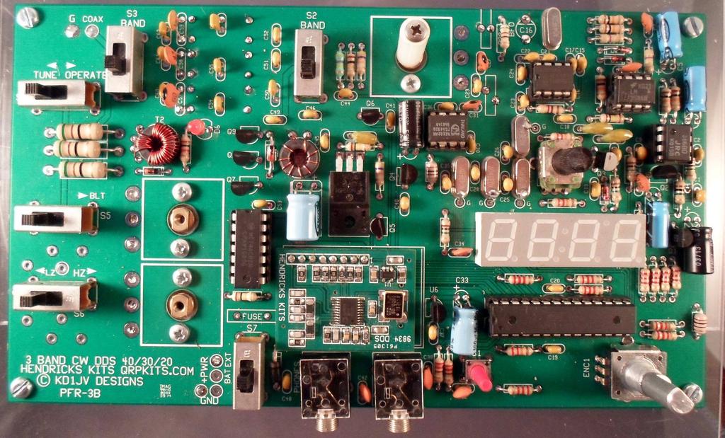
1 PFR-3B Portable Field Radio Specifications: Bands : 40 meters, 30 meters and 20 meters Tuning range: Full band coverage DDS VFO with 50 Hz slow tuning rate and 200 Hz fast tuning rate Mode: CW only Receiver MSD: 0.2 uv typical Selectivity : 300 Hz Four crystal IF filter and 600 Hz center frequency audio band pass filter Receive current, no signal typical: Display on, 47 ma Display off, 34 ma Transmitter: 5 watts at 12.0 volts, all bands +/- 10% Transmitter current: 650 ma (40 M) to 750 ma (20 M) typical at 5 watts. Spurs: - 50 dbc maximum, all bands 5 to 40 wpm internal B mode iambic keyer Two (2) 63 character keyer memories. Coax or balanced line output Built in SWR indicator and BLT (balanced line tuner) Size: 7.2 wide X 4.2 deep X 1.5 high (less knob height). Weight: 18 oz, no batteries installed. Power supply voltage: 8 volts minimum, 12.5 volts maximum. 12 to 9 volts recommend. External power or internal battery pack Pacific Antenna July 2015
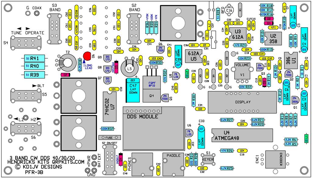
2 Assembly notes: There is no need to print out the whole assembly manual which would use up a lot of ink. Hopefully you have a laptop or similar you can view these instructions on at the work bench. Do print the over all parts placement diagram to use as reference as you build. For experienced builders, that is likely all you'll need for most of the assembly. Pre-sorting the resistors and capacitors can speed up the assembly and reduce mistakes. Parts will be installed in order of hight, starting with resistors. This way taller parts don't get in the way had they been installed first. The placement diagrams highlight the parts to be installed. To reduce clutter on the diagram, parts already installed or to be installed at a later step are not shown, with the exception of a few things for reference. Parts are numbered on the board starting at the lower right hand corner. Numbers run bottom to top, then right to left across the board. Missing or lost parts? Contact QRPKITS.com for replacements.
3
4 Parts list: QTY VALUE QTY VALUE 1 10 ohms Brown, black, black, gold p NPO Disk, brown, black dot on top edge 1 51 ohms Green, brown, black, gold 1 22 p NPO Disk, brown, black dot on top edge ohms Yellow,violet,brown,gold 1 33 p C0G K Red, red, red, gold 1 47 p C0G 5 10 K Brown, black, orange, gold 1 68 p NPO Disk, brown, black dot on top edge 3 22 K Red, red, orange, gold p C0G Mono, yellow or NPO disk 2 47 K Yellow, black, orange, gold p C0G Mono, yellow K Brown, black, yellow, gold p C0G Mono, yellow K Yellow, violet, yellow, gold p C0G Mono, yellow 5 1 MEG Brown, black, green, gold p C0G Mono, yellow 3 51 ohm 2W Green, brown, black, gold p C0G Mono, yellow 1 10K audio Vertical PCB mount p DISK Disk, brown 2 10 uhy rfc Brown, black, black, gold ufd disk Disk, brown 2 SA612AN 8 pin DIP IC ufd X7R Mono, yellow 1 LM358N 8 pin DIP IC ufd film Film, green 1 LM386N 8 pin DIP IC 1 30 p trimmer Green 1 74HC02N 14 pin DIP IC (74AC02 may be supplied) 3 poly-variable Variable capacitor, dual section 1 ATMEGA48 28 pin DIP IC 3 1 ufd / 50V Aluminum electrolytic ufd /16V or 25V Aluminum electrolytic 1 78L05 TO-92 5V reg ufd /16V or 25V Aluminum electrolytic 1 78L06 TO-92 6V reg 4 8 pin DIP sockets 1 2N3906 PNP TO-92 plastic 1 14 pin DIP socket 4 2N7000 TO-92 plastic N MOSFET 1 28 pin DIP socket 3 BS170 TO-92 plastic N MOSFET 2 FT37-43 Ferrite core, gray or black 1 FQPF7P06 TO-220 plastic P MOSFET 6 T37-2 Red Powdered iron core 1 1N4756A Larger glass diode, 47V 1W zener 2 T37-6 Yellow Powdered iron core 1 1N5817 Plastic diode shottky rectifier, 1A 1 T100-2 Red Powdered iron core 4 1N4148 Glass diode 1 12mm mechanical Encoder, w/switch 1 DDS module Built and tested. 1 6mmx13mm tack Push button switch 1 4 dig LED 4 digit multiplexed display module, hi eff 3 DPDT slide switch 1 Super bright LED clear 3 DP3T slide switch 1 DPDT toggle switch MHz Crystals HU-49US 2 Stereo jacks A hold, 1.8A trip PTC resetable fuse 4 Knobs 1 Power jack 2.5 mm pin 1 8 cell AA battery Holder and double sided tape 1 BNC jack 1 Red filter 2 Binding posts 1 Red, 1 Black 1 PC board 1 5 feet #24 hook up wire. 3 Sets of vari-cap mounting hardware 1 5 feet #26 magnet wire 4 #4 lock washers 1 12 feet #28 magnet wire 4 1/ screw
5 Resistors, diodes, RFCs R1 10 OHMS BRN/BLK/BLK/GLD R K RED/RED/RED/GLD R2 1 MEG BRN/BLK/GRN/GLD R26 22 K RED/RED/ORG/GLD R3 2.2 K RED/RED/RED/GLD R K RED/RED/RED/GLD R4 10 K BRN/BLK/ORG/GLD R28 51 OHMS GRN/BRN/BLK/GLD R5 2.2 K RED/RED/RED/GLD R OHMS YEL/BLK/BRN/GLD R6 2.2 K RED/RED/RED/GLD R30 1 MEG BRN/BLK/GRN/GLD R7 2.2 K RED/RED/RED/GLD R OHMS YEL/BLK/BRN/GLD R8 10 K BRN/BLK/ORG/GLD R32 47 K YEL/VOL/ORG/GLD R9 2.2 K RED/RED/RED/GLD R K BRN/BLK/YEL/GLD R K YEL/VOL/YEL/GLD R34 47 K YEL/VOL/ORG/GLD R K RED/RED/RED/GLD R K BRN/BLK/YEL/GLD R12 1 MEG BRN/BLK/GRN/GLD R K YEL/VOL/YEL/GLD R13 1 MEG BRN/BLK/GRN/GLD R K BRN/BLK/YEL/GLD R14 1 MEG BRN/BLK/GRN/GLD R K RED/RED/RED/GLD R K BRN/BLK/YEL/GLD R39 51 INSTALL LATER R K YEL/VOL/YEL/GLD R40 51 INSTALL LATER R17 10 K BRN/BLK/ORG/GLD R41 51 INSTALL LATER R K RED/RED/RED/GLD R18 10 K BRN/BLK/ORG/GLD D1 1N4148 SMALL, GLASS R19 10 K VOL/GRN/RED/GLD D2 1N4148 R K RED/RED/RED/GLD D3, D7 1N4148 R K RED/RED/RED/GLD D4 1N5817 LARGE, BLACK PLASTIC R22 22 K RED/RED/ORG/GLD D5 1N4756A LARGE GLASS R23 22 K RED/RED/ORG/GLD L1 10 uhy BRN/BLK/BLK/GLD R ohms YEL/BLK/BRN/GLD L2 10 uhy BRN/BLK/BLK/GLD
6 Capacitors: Since there are a lot of 0.1 ufd caps, these are highlighted in yellow. The rest of the assorted values are in light blue. We will also install the crystals, highlighted in gray, and are mounted first. Solder a lead clipping from the hole next to the crystal labeled G to the top of the crystal can to ground it. X1 is not grounded. X1-5 CRYSTALS jumper case to gnd C (100 pfd) C (.001 ufd) DISK C1 104 (0.1 ufd) C (100 pfd) C (.01 ufd) FILM C2 104 (0.1 ufd) C (100 pfd) C (0.1 ufd) C3 Electrolytic install later C (0.1 ufd) C (0.1 ufd) C4 Electrolytic install later C (100 pfd) C (0.1 ufd) C5 Electrolytic install later C (100 pfd) C47 Electrolytic install later C6 Electrolytic install later C pfd DISK C (0.1 ufd) C7 471 (470p) DISK C (100 pfd) C (0.1 ufd) C8 102 (.001 ufd) DISK C (150pfd) C (330 pfd) C9 104 (0.1 ufd) C (0.1 ufd) C (220 pfd) C (470p) DISK C31 22 pfd DISK C (151 pfd) C (0.1 ufd) C (.001 ufd) DISK C (0.1 ufd) C (.01 ufd) FILM C33 Electrolytic install later C (680 pfd) C (0.1 ufd) C (.001 ufd) DISK C (560 pfd) C (.01 ufd) FILM C (100 pfd) C (330 pfd) C (0.1 ufd) C (0.1 ufd) C57 68 pfd C (0.1 ufd) C (0.1 ufd) C58 47 pfd C (0.1 ufd) C (.001 ufd) DISK C59 33 pfd C (0.1 ufd) C39 Electrolytic install later C (330 pfd) C (0.1 ufd) C (0.1 ufd) C (220 pfd) C (0.1 ufd) C (0.1 ufd) C (150 pfd)

7 Most everything else: Parts should be installed in the order in which they are listed in the table below. LED Display This will go in only one way as there are two missing pins and corresponding pads. U4,20 pin DIP socket When installing sockets, double check the leads to make sure none of them are folded over under the socket. This is very hard to fix once you start soldering! U7, 14 pin dip socket U1, U2, U3, U5, 8 pin Phone and paddle jacks Make sure they are set flush to the board. R39, R40 and R41 51 ohm, 2 watt resistors Green/Brown/Black/gold Q1 2N3906 Q2, Q3, Q5, Q6 2N7000 Q7, Q8, Q9 BS170 Q4 U6 U8 FQPF7P06 You may receive a different number any FQPFxPxx will work. 78L05 Check the number very carefully so as not to mix up with U8 78L06 The electrolytic caps are installed laying flat to the board. The value indicated on the diagram is in pfd. 105 = 1,000,000 pfd = 1 ufd C4, C5, C6 (105) 1 ufd Aluminum Electrolytic. Long lead is plus, black stripe on can is negative. C3, C33, C39 (107) 100 ufd Aluminum Electrolytic C47 (227) 220 ufd Aluminum Electrolytic S4, S5, S6 DPDT slide switch S2, S3, S7 DP3T slide switch S1 ENC1 V1 D6 When installing the switches, make sure the switch is set square to the board before soldering more then one pin! If the switch is tilted, it may not fit into the slot in the enclosure. Long handled Tactile push button switch Mechanical rotary encoder. 10K variable resistor. LED diode. Space off board 1/4 to bottom of the LED.

8 Parts mounted on bottom of board: Several parts mount on the bottom of the board. These are the variable capacitors, the toroid coils, the BFO trimmer and the resetable fuse. CV1, 2, 3 CT1 Fuse Mount these three variable caps to the bottom of the board, using the short screws supplied. BFO trimmer. Make sure the flat side of the cap faces the line in the part outline, towards the top edge of the board. The outline is shown on the top side, but is mounted on the bottom. Winding the toroids: The wire needs to be wound snug to the core. A loose, sloppy winding job will result in poor performance. A turn is each time the wire passes through the center of the core. Miss counting and having an extra turn is a common mistake and will result in low power output. Make sure you tin the wire leads before trying to solder the wire to the board! And make sure you don't pull the wire through the pad past the tinned area of the lead. You can tin with your iron with a blob of solder at the tip. L6 18 turns (11 #28) on T37-2, Red core 40M L7 21 turns (12.5 #28) on T37-2, Red core 40M L8 13 turns (9 #28) on T37-2, Red core 30M L9 18 turns (11 #28) on T37-2, Red core 30M L10 14 turns (9 #28) on T37-6, Yellow core 20M L11 18 turns (11 #28) on T37-6, Yellow core 20M L13 40 turns #28 (22 ) on T37-2, Red core Rx in L14 40 turns #28 (22 ) on T37-2, Red core Rx in L5 and T2 These mount to the top of the board. L5 T2 8 turns #28 (5 ) on FT37-43 core (Black) 25 turns #28 (15 ) on FT37-43 core (Black) plus 5 turns #28 (3 ) for primary. First wind the 25 turns which is the secondary. Then wind the 5 turn primary in the space between the wire ends of the 25 turn secondary. The 5T primary wires go to center two pads of the outline. The secondary to the two outside pads.
 Start the winding of the core by passing the starting end of the wire into the hole from the bottom of core.")

 slightly away from the middle, outside edge of the core.")
9 Winding and mounting of T1: Cut a 24 (2 foot) length of the # 26 wire. Wind 12 turns on the T100-2 core (this is the large red core) Start the winding of the core by passing the starting end of the wire into the hole from the bottom of core. Wind the rest of the turns in a counter clock wise direction, passing the long end of the wire down into the core from the top. Winding the core in this fashion will make the ends of the wire more or less line up with the staggered holes in the board. Try to wind the wire fairly flat to sides of the core. Space the turns so that they cover about ½ of the core. See photos at bottom of this page. Pull the 6 th turn on the outside of the core (counting from the left hand starting end) slightly away from the middle, outside edge of the core. Scrape away the insulation on the wire of this 6 th turn, near the middle of the core. Cut a 2 length of the # 26 wire and tin one end. Attach this wire to the 6 th turn on the core. Make a small, half loop on the end of the wire and lightly crimp to wire on core, then solder. Cut a 18 length of the # 26 wire and wind 6 turns inter-weaved between the first winding and centered around the tap you just made, so there are 3 turns on either side of the tap. It is easiest the start the winding of these turns from the center tap of the first winding. Now cut a 8 length of the # 26 wire and wind 1 turns on either side of the tap, for a total of 2 turns. This winding will also be inter-weaved between the other two windings. Push the windings together so they are close to each other and not spaced around the core. Before mounting T1 to the board, solder in the wires which will connect to the binding posts into the holes labeled BP. (4.5 long) These wire will pass through the center of the core. If the wires are not installed now, it is difficult to do once T1 is mounted in place. The core is mounted to the bottom of the board and the wires are soldered from the top. Suspend the core slightly off the bottom of the board so that the wires do not touch the ends of the switch mounted above it. The thick magnet wire can be difficult to tin properly, so verify connections have been made with an ohm meter. Primary winding of T1 with center tap T1 with HI-Z and LOW-Z winding DDS Module: The final step is to install the DDS module. This gets soldered in place as there isn't enough head room for a socket. The module is installed on the top side of the board and can only go in one way. Once soldered in place, clip the SIP pins flush to the board. If they are not trimmed back, they may short to the batteries in the internal battery pack.
10 Testing and calibration: The board is now complete except for installing the ICs. Give the BFO trimmer (CT1) about a ¼ turn from its factory setting. If you look closely in the trimmer hole, you will see an arrow at one end of the screwdriver slot. When the arrow points towards the flat side of the body, it is a maximum capacitance. When it points to the round end opposite the flat end, it is at minimum. If you have some 1/ screws and nuts or threaded spacers, put these in the four corner mounting holes to rise the board off your bench. Otherwise, clean the work space of wire clippings and solder blobs. Wire up the power jack and BNC jack to the board. Wrap a piece of tape around the leads of the power connector so there isn't a chance the B+ can short to something on the board as you flop it around to work on. Initial tests: Connect a 9 to 12 volt power source to the board and use the power switch on the board to turn it on. Check for proper voltages from the regulators. There should be +5V on pin 14 of U7 and +6 volts on Pin 8 of U5. If the voltages are correct, disconnect power and install the MEGA48 processor into the U4 socket. Power up the board again and the power up sequence should be seen on the display. 1) all segments light for a second, 2) 40, 30 or 20 will be shown depending on which band the band select switch is set to and then 3) the initial operating frequency. You can now test the tuning and Menu switch for proper operation. Refer to the operating instructions. Remove power again and install the rest of the ICs. U1, LM386 / U2, LM358 / U3, SA612A / U5, SA612A / U7, 74AC02 or 74HC02 Connect an antenna to the BNC jack and restore power. You should now be able peak the receiver input tuning and to hear stations. (Attach the nylon spacer shaft extender to the variable cap to make it easier to adjust) Transmitter testing: Turn the power off and then disconnect the antenna and connect up a suitable QRP power meter and dummy load. Make sure the TUNE / Operate switch is in the Operate position and the coax / BLT switch is in the Coax position. Plug in a paddle or straight key. If using a paddle, you can hold the dash paddle closed when turning the power on to set the rig to straight key mode. Then the dot paddle will key the transmitter on and off. You can now turn the power back on and key the transmitter. Power output depends on supply voltage. With a 9.0 V supply, power out should be about 2.5 watts on all bands. With 12.0 V supply power out should be between 4.5 and 5 watts on all bands. Tweaking power output: Power output is affected by the spacing of the turns on the input side coil for the low pass filter. This would be L6, L8 or L10 for 40, 30 and 20 respectively. If power output is too high, move some of the turns closer together. If it is too low, spread the turns out as best can be done. If the power out is much lower then expected, this is usually due to have an extra turn on the core or a very loosely wound one. Although some times the problem is simply a power meter which is not very accurate at these power levels. SWR bridge testing: Set the TUNE / Operate switch to TUNE, disconnect the dummy load and transmit. The LED should light brightly. Now reconnect the dummy load and transmit again. The LED should be off or very dim. BLT testing: The Balance Line Tuner is more easily tested once the board is wired up into the enclosure, but you can do that now if you like. If there is a problem it will be easier to fix with the board out of the case. First install the wires to the board to the output of T1 which will connect to the binding posts. Now connect the BNC jack to these wires. It doesn't matter which one is ground. Attach the shaft extenders and knobs to the variable caps to make then easier to adjust. Connect your dummy load and also your power meter if you like. Set the Tune/operate switch to Tune and the Coax/BLT switch to BLT. Set the Hi Z/ Low Z switch to Low Z. Refer to the operating instructions later in the manual for how to use the BLT. Tuning is very touchy and it takes some practice. Doing this now into a dummy load is a good way to not only verify operation, but to get that practice.
11 If you compare the power out between direct and via the BLT, you will notice a few 100 mw loss in power while using the BLT. DDS frequency calibration and precise BFO setting adjustment: If you have an accurate frequency counter, the DDS frequency can be calibrated. Without calibration, the operating frequency maybe off by a few 100 Hz on the 20 meter band and to lesser extent on the lower bands. This is due to variations in the reference clock oscillator for the DDS chip. Calibration is done at ,000 MHz, so it could be possible to zero beat WWV, but it is better left alone if an accurate frequency counter is not available. It is also possible to tweak the IF offset frequency to ensure it is centered in the passband of the crystal filter. This adjustment is done with the aid of an Oscilloscope, which could be a virtual one running on PC, as all you need to see is audio frequencies. The IF offset adjust mode is also used to set the BFO trimmer for the proper offset to match the audio band pass filter. NOTE: If you do not have the equipment to do the frequency and offset calibration, these steps may be skipped, leaving the default values in place. You will need to click through to the BFO setting part of the calibration to set the BFO trimmer cap. This is done by first entering the calibration mode as described below and clicking the MENU switch once to get to the Offset and BFO adjustment step. Entering Calibration modes: While holding the DOT paddle and MENU switch closed, turn power on to the board. The LED display will read [CAL.r]. Reference frequency calibration: Connect a frequency counter to the TP1 test point at R37. Use the tuning knob to adjust the frequency to exactly ,000 MHz. Once adjusted, click the MENU switch to advance to the IF offset and BFO trimmer adjustment. IF offset adjust and BFO trimmer set: Once the MENU switch has been clicked, the LED display will now read [CAL.o]. If you do not have an Oscilloscope, do not make any adjustments to the IF offset frequency and just go do the BFO adjustment. Connect an Oscilloscope to Pin 7 of U2. You will see the audio beat note on this pin. Tune through the pass band of the crystal filter using the tuning encoder. You will likely see the amplitude of the signal peak a little at the edge of the pass band, just before the amplitude rolls of sharply. Tune to one end of the pass band, the point the amplitude of the signal starts to roll off. Count how many clicks of the tuning knob it takes to get to the other end of the pass band. Divide that number by 2 and tune back up or down depending on which way you went initially by that number of clicks to center the frequency in the pass band of the filter. BFO adjustment: Plug headphones into phones jack and you will hear the BFO beat note. Reduce the volume to ensure the AGC circuit is not active. Adjust the BFO trimmer cap CT1 for a peak in the volume, which should occur at about 600 Hz. For best results, an Oscilloscope connected to the headphone jack should be used. Problems? Refer to the trouble shooting guide at the end of the manual. For technical help, the designer at Steve.kd1jv@gmail.com If the problem can not be resolved by , a repair service is available for a small, nominal fee.

12 Wiring the board into the enclosure. 1. Remove the shaft extender(s) from the variable cap(s). 2. Before mounting the board, solder the wires which will connect from T1 to the binding posts to the board. 3. Secure the red LED filter over the display opening inside the enclosure, using clear shipping tape. 4. Mount the board into the top of the enclosure, using the four /4 screws and lock washers. The board needs to be angled and wiggled a little to get ends of the paddle and headphone jack to snap into the holes on the front side of the case. 5. Install the power jack, binding posts, DPDT toggle switch and BNC jack to the rear panel. Wire as shown below. Power jack wiring should be routed the long way directly across the board from the jack and then along the front edge of the enclosure. Battery holder mounting: Mount battery holder to bottom of cabinet as shown below. These are attached to the bottom side of the cabinet with double sided tape, which is already attached to the bottom of the holders. Make sure you identify the front of the cabinet piece correctly. Leave a small space between the sides of the battery holders as when the batteries are installed they will billow out the sides a little. Connect the wires to the battery holder terminals as shown the diagram below. Be quick about soldering the wires, as the plastic will melt if you leave the iron on too long. Wire the [+] terminal to pad labeled BAT next to power switch and the [-] terminal to the pad labeled GND
13 Operation: Power supply: The PFR-3B rig should be powered by no more than about 12 volts and no less then 8 volts. Maximum supply current at full transmitter output is typically less than 800 ma. If a 13.8 volt bench supply is used to power the rig, two silicon rectifier diodes should be added in series with the positive supply lead to drop the voltage down closer to 12 volts. This will ensure the rig does not put out more than about 5 watts. 5 watt output at 12 volts was chosen as this is the typical voltage a gel-cell battery settles down to after it has been removed from its charger. Below 8 volts, the 6 volt regulator for the receiver will start to loose regulation. Since transmit power output is dependent on supply voltage, a variable supply is a handy way to adjust the power output level. At the minimum supply voltage of 8 volts, the transmitter will deliver about 2 watts output. Transmitter current will also be reduced at lower supply voltages, extending battery life. Power switch: The power switch has three positions. OFF, Internal (battery) power and External power. When the rig is first turned on, the display will show all 8 s for a few seconds. This is the segment display test. Then the display will indicate the currently selected band, 20, 30 or 40. The band numbers will be displayed for another couple of seconds, then the display will change to show the operating frequency. Since only four digits are available, only the 100 khz to 100 Hz digits are displayed. MHz digits are implied by the currently selected band. The initial operating frequencies loaded when the rig is powered on or when the band is changed are 7.030,000 MHz for 40 meters, ,000 MHz for 30 meters and ,000 MHz for 20 meters. Once on, the last used frequency for each band is restored when changing between bands. Selecting operating band: Two slide switches are used to select the operating band. Both switches MUST be in the same band position for proper operation. The band switch located near the top, center of the cabinet tells the processor which band you want to use and will indicate the selected band on the display for a second when the band is changed or on power up, as noted above. The switch located near the top, left of the cabinet is used to connect the output of the low pass filter to the antenna. If the two band switches are not in sync, there will be no signals in the receiver and of course, no transmitter output. Although transmitting with improper switch settings will not damage the transmitter, it is not recommended to do so. After you change bands, you must re-peak the receiver input with the Rx peak control. Tuning: Tuning is done with the tuning knob. Tuning steps are in 50 Hz increments. Each detent will change the frequency by 50 Hz. Since the display only has 100 Hz resolution, it will take two clicks of the encoder to see a change of frequency on the display. Changing tuning rate: The tuning rate can be toggled between normal 50 Hz rate and a fast tune rate of 200 Hz by pushing and holding down the tuning knob for longer then 1 second. The letter F will be annunciated if the 200 Hz rate is toggled on or S for the normal rate of 50 Hz. Tuning limits: Tuning is restricted to be within the currently selected ham band. This is to prevent out of band transmission. Full band coverage is available ,000 to 7.300,000 on 40, ,000 to ,000 on 30 and ,000 to ,000 on 20. Even though you can tune into the phone band, although SSB signals will not be intelligible due to narrow CW filter. Volume control and AGC: The PFR-3B incorporates an audio derived AGC circuit on the audio output amplifier. This helps to limit the volume when a strong station is encountered. This limits the signal to 1.2V p-p or about 11 mw into a 16 ohm load. However, this is still enough to result in a very loud volume when using efficient ear bud type headphones so it is wise to turn the volume down before scanning the band. You will also want to keep the volume turned down enough to keep the AGC from activating in the first place.
14 RIT (receiver incremental tuning) Momentarily pushing the Tuning knob for less then 1 second will activate RIT. The display will change to display [ r -0.0 ] The 'r' indicates RIT mode is active and -0.0 shows the displacement from the transmit frequency, up to + or 9.9 khz. Checking Rx frequency without exiting RIT mode: Clicking the MENU switch will toggle the receive frequency back to being equal to the transmit frequency. The display with change to [ = 0.0 ] and the tuning is locked out in this mode. You can however transmit. MENU switch : The MENU switch is used to access various functions, mostly related to the keyer operation. Note: When in straight key mode, none of the MENU switch functions are available, with the exception of sending keyer message 1, assuming a message is already stored in that location. Menu functions are selected by a repeated click and release of the MENU switch. To active a function, simply stop clicking the switch when the desired function is displayed. Functions are selected in the following order: (note, decimal point is always on) Code speed: Display [ C 2.0] Tune mode: Display [ t. ] Side tone : T DFE mode: Display [ ] Side tone : D Enter message Display [ --. ] Side tone : M Changing keyer code speed: The current code speed is shown on the display as [C x.x], where x.x is the current speed. Ignore the decimal point. The Keyer speed is changed by using the tuning knob. Turn clock wise to increase speed, counterclockwise to decrease speed. Once the desired speed is selected, exit by clicking the MENU switch. Tune Mode: This mode is used if you want to key a steady carrier for measuring power output or when adjusting the antenna tuner. However if you just need to tweak the tuner, it is quicker and less stressful on the PA to simply send a string of dots as you fiddle with the tuner. To enable tune mode, click and release the MENU switch twice until the letter T is annunciated by the side tone and something which looks like a t is displayed. The transmitter can now be keyed by closing and holding closed either the dot or dash paddle. When you wish to return the rig to normal operation, click the MENU switch. NOTE: there is a minor bug in this routine. The first time you key the transmitter, the side tone starts but the transmitter doesn't produce any output. Release the paddle and key it again and it will start to work properly. DFE mode (direct frequency entry) This mode allows you to go directly to a specific frequency by entering it in with the paddle. This is useful if you want to make large frequency shifts, which might otherwise take a lot of tuning knob twisting. To enter DFE mode, click and release the MENU switch three times. The display will change to [ ] and the letter D will be annunciated by the side tone. Enter the desired frequency, starting with the 100 khz digit and finishing with the 100 Hz digit. As each digit is entered, it will be shown on the display and shift from right to left as additional digits are entered. If a number is not recognized, a? will be annunciated by the side tone. Once the 100 Hz digit is entered, the rig will re-tune to that frequency provide it is within the normal tuning limits of the current band. If it outside the band, the frequency at which the rig was tuned to when DFE was enabled will be restored and DFE mode exited. If you make a mistake or wish to exit the DFE mode at anytime before the 100 Hz digit is entered, you can escape by clicking the MENU switch. Note: DFE mode is not available if RIT is on.
15 Storing a message: Click and release the MENU switch 4 times to enter the Message store mode. The display will show [ --. ] and the letter M will be annunciated by the side tone. The receiver is then muted and you can now start to enter your message by using the paddle. If you accidentally activate this mode and do not wish to enter a message, click the MENU switch to abort before touching the paddle. The Letter X will be annunciated and the rig will go back to normal operation. Up to 63 characters (including word spaces) may be entered. If you exceed this limit, the letters EM will be annunciated by the side tone and you will have to start again. Note that ideal letter and word timing is used to determine letter element groups and word groups. Of these two, the letter timing is most critical. If do not pause long enough before starting a new letter, a letter space will not be detected. If you pause too long, it will be interpreted as a word space. It may take some practice to enter a message correctly. To ensure a word space is inserted, it is best to pause somewhat longer than you normally would between word letter groups. Many people run their letters and words together by not leaving enough space between letter element groups. If your message come out gibberish, you have that problem. When you have finished entering the message, click the MENU switch. The message you have entered will be annunciated by the side tone so you can check the accuracy of the message. If it sounds good, store it by closing either the DOT or DASH paddle. DASH will store it into message location 1 and DOT into location 2. If you wish to redo the message, click the MENU switch again. EM will be annunciated by the side tone and you can now re-enter the message. Sending a message: To transmit one of the two messages, click and hold close the MENU switch, then tap the dash paddle to send message 1, or the Dot paddle to send message 2, then release the MENU switch. If a message has not yet been stored, releasing the MENU switch will activate the change code speed mode. Once started, a message can be terminated by closing the DOT or DASH paddle. The paddles are tested in between the transmission of characters, so hold the paddle closed long enough to be sensed. Straight key mode: If a monaural plug is in the paddle jack at power up (the sleeve grounds the dash input pin), the rig will power up in straight key mode. This allows using either a straight key or external keyer. While in straight key mode, none of the keyer switch functions will be available. If a message has been previously stored in the keyer memories, only memory location 1 will be available, (tap the straight key closed with in 1 second of clicking the keyer switch) as this is selected with the dot input pin, now controlled by the straight key. Using the SWR bridge and BLT tuner: TUNE / OPER SWITCH: Sliding TUNE / OPER witch to the TUNE position switches in the SWR bridge. The LED will now indicate the relative amount of SWR. The brighter the LED, the higher the SWR is. When the LED is not lit or is very dim indicates 1:1 SWR. COAX / BLT SWITCH The COAX / BLT switch is used to switch between a direct coax connection to the BNC jack or the BLT (balanced line tuner). The Coax position is of course used if you are using a resonate, coax feed antenna or an external tuner. The BLT position is used when the built in tuner is desired and is normally used with ladder line feed antennas, but can also be used for end feed antennas or possibly matching coax feed antennas which need a little tweaking. Balanced / unbalanced switch: The toggle switch on the rear panel is used to switch between balanced and unbalanced feed lines. Use the unbalanced mode when matching to a coax feed line or matching directly to an end feed antenna wire. When the handle of the toggle switch faces the binding posts, the BNC jack is connected to the output of the BLT and one side of the BLT output winding is grounded. Note: The handle of the switch on the rear panel should be facing towards the coax jack when using either a balanced line on the binding posts or a coax feed antenna which is not using the tuner. Using the BLT:
16 Learning to use the tuner takes some practice. The best way to practice and to learn how to operate the tuner is by transmitting into a dummy load. Once you do find a match, if you mark the knob settings on the case you will find these settings will repeat very closely for a wide range of loads and will provide a good starting point. Set the knobs on the capacitor shafts to point towards the center of the case as they are rotated. This gives you the space to add the dial markings. Use different color markers for each band. If you don't want to do this directly on the case, use a piece of heavy paper like from an index card and then laminate it. Before transmitting, adjust the TUNE and LOAD capacitors for best band noise or signal strength. Now switch from Operate to Tune mode with S7. Now transmit a string of dits or dahs and fine tune the TUNE and LOAD capacitors so that the SWR LED gets very dim. This of course, is easier said than done. The tuning is very sharp and if you tune too fast you will never see the LED get dim. A further complication is the Load and Tune controls are interactive. First slowly adjust the LOAD until you see even the slightest dimming of the LED. Now adjust the TUNE and see if you can make it even dimmer. Go back to LOAD and see if this will dim the LED farther. If no farther improvement can be made, advance the TUNE slightly (try clockwise first) which will make the LED brighter again, then readjust the LOAD. Working back and forth a few time between the Tune and Load controls should enable you to make the LED become very dim or go out completely. In most cases when using a ladder line feed antenna, you will use the HI-Z setting of the BLT. In some cases, you may only be able to find a match using the Low-Z setting. Using the BLT with end feed wire antennas or coax. Switching the handle of the rear panel switch so it faces the binding posts will ground the black balanced line binding post and connect the Red post to the coax jack. End feed wire antennas can now be connected to the Red binding post and a counter pose to the Black post. Use the High Z position of S9 if the wire is near a 1/2 wave in length. Use the Low Z position if the wire is near a ¼ wave or less in length. The Low Z position is also used when using the BLT to match a coax feed antenna. Fuses: A solid state, self resting fuse is built into the circuit. This fuse will trip if the current exceeds 1.5A. This is enough to prevent a fire or damage to your power supply if a serious short develops inside the rig. However, it is still a good idea to have a 1 A, fast blow fuse in the power supply cord. Paddle wiring: The paddle jack uses standard wiring: Tip is Dot Ring is Dash Sleeve is ground Straight key: Use a mono plug or ground the ring of a stereo plug. There is no paddle sense reverse built into the firmware.
17 Troubleshooting: More often then not, any trouble with the board not working is inevitably tracked down to soldering issues, so this is the first thing to look for. Looking at the solder pads at the TOP of the board can be helpful. If the hole around a part lead isn't full of solder, it probably isn't soldered on the bottom. Solder can stick to the lead and look soldered, but didn't actually flow into the hole. Another common issue is the tinning of the magnet wire used to wind the toroids. Even if you pre-tinned the wire, sometimes it gets pulled through the pad past the tinned area. Use an ohm meter to verify continuity through the coil. Less common are miss-placed parts. Resistors are most susceptible to ending up in the wrong place if the color code is miss-read. Even rarer are bad parts. IC's almost never go bad these days and most will survive being powered up if they were installed backwards. The 2N700 and BS170 MOSFETs are static sensitive, so it is possible for these to be damaged by handling, but again is rare. If you can't spot the problem visually, time to break out the test equipment. For most of you, that will be a DVM, but it's a lot quicker if you have a signal generator and Scope available. Turning on the Offset cal mode effectively turns the DDS module into a signal generator at the IF frequency and can be used to troubleshoot the all the receiver stages except for the first mixer signal input. If you can hear the beat note in the Cal mode, you know everything from the input of the first mixer (U5) to the headphones is working and your problem is in the input filter or QSK switch. The transmitter is as simple as it gets and rarely has problems, other then low power out which is always related to the output filter. If there is no power output, make sure the connections to L5 are good and that Q10 is turning on (and off!). The IC voltage tables below might help in determining a problem area. These voltages can vary +/ volts depending on the voltage output of the regulators and possible loading by your voltmeter. Don't be concerned unless the voltage is way off. IC U4 MEGA 48 MPU processor Rx Tx Pin function Pin 1 5 or V Side tone Pin V 0 V Paddle DOT in U3,U5 SA612 mixer Pin V IN Pin V IN Pin 3 0 V GND Pin V OUT Pin V OUT Pin V OSC Pin V OSC Pin V V+ IC U2 LM358 op amp Pin V OUT Pin V - IN Pin V + IN Pin 4 0 V GND Pin V + IN Pin V - IN Pin V OUT Pin V V+ IC U1 LM386 audio Pin V Pin 2 0 V - IN Pin 3 0 V + IN Pin 4 0 V GND Pin 5 2.9V OUT Pin 6 6.0V V+ Pin 7 3.0V Pin V IC U7 74HC02 NOR GATE Rx Tx Pin 1 0 V RF out Pin 2 0V 0V in Pin 3 5V RF in Pin 4 0V RF out Pin 5 5V RF in Pin 6 0V 0V in Pin 7 0V 0V GND Pin 8 0V RF in Pin 9 0V 0V in Pin 10 5V RF out Pin 11 5V RF in Pin 12 0V 0V in Pin 13 0V RF out Pin 14 5V 5.0V Vcc Pins 1, 4 and 13 will measure about 2.5 volts with most DVM's when transmitting steady carrier. In and out pins have square wave signal when transmitting. Pin V 0 V Paddle DASH in Pin 4 5 V 5 V encoder Pin 5 5 V 5 V encoder Pin Digit 4 Pin V 5.0 V Vcc Pin 8 0 V 0 V GND Pin a segment Pin c segment Pin Digit 3 Pin Digit 1 Pin Digit 2 Pin d segment Pin f segment Pin b segment Pin g segment Pin dp segment Pin e segment Pin V 5.0 V AVcc Pin V 5.0 V Aref Pin 22 0 V 0 V GND Pin /4.0/4.7 40/30/20b and sw A/D sw input Pin 24 5V 0V MUTE OUT Pin 25 0 V 5.0 V Tx enable Pin 26 0 or 5 DDS clock Pin 27 0 or 5 DDS data Pin 28 5V 5V DDS load
18 Schematics:
19
The PFR-3 Three band Portable Field Ready QRP CW Transceiver 40/30/20 meters Hendricks Kits KD1JV Designs
 The PFR-3 Three band Portable Field Ready QRP CW Transceiver 40/30/20 meters Hendricks Kits www.qrpkits.com KD1JV Designs Production manual 6/10/08 Rev B Specifications: PFR-3 shown with optional paddle
 The Mountain Topper by Steve Weber (KD1JV) (MTR) www.lnrprecision.com FULLY ASSEMBLED Manufactured by LNR Precision, Inc. A very small, very efficient three band QRP CW rig. Specifications: Three bands,
MTR-3B - LCD edition
 MTR-3B - LCD edition Mountain Topper User Manual Overview: The Mountain Topper Rigs are designed to be a very small, light weight, very battery efficient, multi-band CW rig suitable for field operation.
Dual Band HF CW transceiver
 Dual Band HF CW transceiver Hendricks kits and KD1JV Designs QRPKITS.COM Specifications: Any two ham bands, 80, 40, 30, 20, 17 or 15 meters, choose at time of order. 5 watts output on all bands with 13.8V
Dual Band HF CW transceiver Hendricks kits and KD1JV Designs QRPKITS.COM
 Dual Band HF CW transceiver Hendricks kits and KDJV Designs QRPKITS.COM Updated 5//9 Specifications: Any two ham bands, 8, 4,,, 7 or 5 meters, choose at time of order. 5 watts output on all bands with.8v
LNR Precision Mountain Topper MTR-4B and MTR-5B REV 2.0 User Manual for use with versions with 16 x 2 display.
 LNR Precision Mountain Topper MTR-4B and MTR-5B REV 2.0 User Manual for use with versions with 16 x 2 display. Four band MTR 4B shown Overview: The Mountain Topper Rigs are designed to be a very small,
The DCxxB family of transceivers
 The DCxxB family of transceivers High performance Direct Conversion transceivers for 40, 30 and 0 meters. A KDJV Melt Solder design Distributed by Pacific Antenna www.qrpkits.com Join Yahoo's DC40 kits
The KD1JV Tri-Bander CW transceiver QRP kits dot com
 The KDJV Tri-Bander CW transceiver QRP kits dot com www.qrpkits.com Table of Contents Operation:... Message pause and stop...3 Power on/off:... Straight key mode:...3 Band selection:... Tune up mode:...
N3ZI Kits General Coverage Receiver, Assembly & Operations Manual (For Jun 2011 PCB ) Version 3.33, Jan 2012
 Version 3.33, Jan 2012") N3ZI Kits General Coverage Receiver, Assembly & Operations Manual (For Jun 2011 PCB ) Version 3.33, Jan 2012 Thank you for purchasing my general coverage receiver kit. You can use the photo above as a
N3ZI Kits General Coverage Receiver, Assembly & Operations Manual (For Jun 2011 PCB ) Version 3.33, Jan 2012 Thank you for purchasing my general coverage receiver kit. You can use the photo above as a
Read This Page First
 Read This Page First If you are reading this you know the manuals are always available at QRPKITS.com. This is version 8.0 of the manual dated 4/27/2016. There is no need to print out the whole assembly
The MBDC. A Multi-Band, Direct Conversion Transceiver. Steven Weber, KD1JV Distributed by Pacific Antenna,
 The MBDC A Multi-Band, Direct Conversion Transceiver Steven Weber, KD1JV steve.kd1jv@gmail.com Distributed by Pacific Antenna, www.qrpkits.com Specifications: Rx current: 80 M : 70 ma, 160 M : 100 ma Sensitivity:
The KD1JV Tri-Bander CW transceiver Hendricks QRP kits
 The KDJV Tri-Bander CW transceiver Hendricks QRP kits www.qrpkits.com Table of Contents Operation:... Setting keyer Iambic A or B mode:... Power on/off:... Straight key mode:... Band selection:... Tune
Pacific Antenna Simple Keyer Kit
 Pacific Antenna Simple Keyer Kit Specifications and Features: Speed range of 5 to 30 wpm Operates in either iambic A or B mode, with B being the default 2 message memories Tune and Beacon modes Built on
The Deluxe Tenna Dipper Design by: KD1JV Distributed by: Hendricks QRP kits,
 The Deluxe Tenna Dipper Design by: KD1JV Distributed by: Hendricks QRP kits, www.qrpkits.com The Tenna Dipper provides a simple means of determining the 50 ohm resonate frequency of an HF antenna or ATU
QRPGuys Michigan Mighty Might Plus 40M Transmitter
 QRPGuys Michigan Mighty Might Plus 40M Transmitter First, familiarize yourself with the parts and check for all the components. If a part is missing, please contact us and we will send one. You must use
Pacific Antenna SLT+ Switched Long wire Tuner
 Pacific Antenna SLT+ Switched Long wire Tuner The SLT+ is designed to match the high impedance load of an end feed, half wave antenna wire to a 50 ohm transmitter using manually switched inductors and
Assembly Manual for VFO Board 2 August 2018
 Assembly Manual for VFO Board 2 August 2018 Parts list (Preliminary) Arduino 1 Arduino Pre-programmed 1 Faceplate Assorted Header Pins Full Board Rev A 10 104 capacitors 1 Rotary encode with switch 1 5-volt
The MBDC. A Multi-Band, Direct Conversion Transceiver. Steven Weber, KD1JV Distributed by Hendricks kits,
 The MBDC A MultiBand, Direct Conversion Transceiver Steven Weber, KDJV steve.kdjv@gmail.com Distributed by Hendricks kits, www.qrpkits.com Specifications: Features: Rx current: X6 LCD display 8 M : 7 ma,
Building a Bitx20 Version 3
 Building a Bitx20 Version 3 The board can be broken into sections and then built and tested one section at a time. This will make troubleshooting easier as any problems will be confined to one small section.
The DCxxB family of transceivers
 The DCxxB family of transceivers High performance Direct Conversion transceivers for 40, 30 and 20 meters. Evolution of the popular DC40 to the DCxxB series on 40,30 and 20 meters A KD1JV Melt Solder design
The DC40. A high performance Direct Conversion 40M transceiver. A KD1JV Melt Solder design Distributed by Hendricks QRP KITS
 The DC40 A high performance Direct Conversion 40M transceiver. A KD1JV Melt Solder design Distributed by Hendricks QRP KITS www.qrpkits.com 1 The DC40 A Direct Conversion, fixed frequency Transceiver.
HT-1A Dual Band CW QRP Transceiver. Kit Building Instructions
 HT-A Dual Band CW QRP Transceiver Kit Building Instructions Rev B, July 8, 08 Designed by BD4RG Exclusively distributed by CRKITS.COM and its worldwide distributors Join the group http://groups.io/g/crkits
KN-Q10 Assembly Manual
 KN-Q10 Assembly Manual Translated by Adam Rong, BD6CR/4 with permission from Ke Shi, BA6BF Edited by Stephen, VK2RH Revision B, Oct 14, 2010 Thank you for purchasing the KN-Q10 4 Band SSB/CW Dual Mode
WA3RNC 30 METER CRYSTALPLEXER TRANSMITTER KIT ASSEMBLY INSTRUCTIONS
 WA3RNC 30 METER CRYSTALPLEXER TRANSMITTER KIT ASSEMBLY INSTRUCTIONS Description The WA3RNC 30 Meter Crystalplexer is a low power crystal controlled QRP transmitter offering a significantly improved tuning
Connecting the FCC-2 to the Hendricks DC Kits Bob Okas, W3CD
 Connecting the FCC-2 to the Hendricks DC Kits Bob Okas, W3CD This is an application note that describes how you can connect the NorCal FCC-1/2 combination to the DC kits. It involves a few extra components
SoftRock v6.0 Builder s Notes. May 22, 2006
 SoftRock v6.0 Builder s Notes May 22, 2006 Be sure to use a grounded tip soldering iron in building the v6.0 SoftRock circuit board. The soldering iron needs to have a small tip, (0.05-0.1 inch diameter),
Assembly Manual V1R2B-Rev1.0D
 Assembly Manual V1R2B-Rev1.0D for 4 State QRP MagicBox - Solid State Transmit/Receive System Designed by: Jim Kortge, K8IQY Copyright 2009-2012 - All rights reserved This system is the result of some brainstorming
Building the Sawdust Regenerative Receiver
 Building the Sawdust Regenerative Receiver Introduction The Sawdust is a super regenerative receiver using the basic Armstrong design architecture. The receiver uses one toroidal transformer to provide
Building the Sawdust Regenerative Receiver
 Building the Sawdust Regenerative Receiver Introduction The Sawdust is a super regenerative receiver using the basic Armstrong design architecture. The receiver uses one toroidal transformer to provide
Building and Operating: Son of Zerobeat A PIC based CW zerobeat indicator from Jackson Harbor Press
 Building and Operating: Son of Zerobeat A PIC based CW zerobeat indicator from Jackson Harbor Press Ed Nisley, KE4ZNU, wrote an article published in the August, September and October of 1996 issues of
Arizona ScQRPion QRP Club. Ft Tuthill w DC CW Transceiver for 80m Part 1 of 2. by Dan Tayloe, N7VE. Ft Tuthill Page 1 of 31
 Arizona ScQRPion QRP Club Ft Tuthill 80 2.5w DC CW Transceiver for 80m Part 1 of 2 by Dan Tayloe, N7VE Page 1 of 31 Table of Contents Specifications... 4 Specifications... 4 Receiver... 4 Transmitter...
The NADC. A CW rig using Nearly All Discrete Components Manual for 40 meter and 30 meter versions Hendricks QRP Kits
 The NADC A CW rig using Nearly All Discrete Components Manual for 0 meter and 30 meter versions Hendricks QRP Kits www.qrpkits.com Show with optional Digital Dial installed Specifications: Receiver: Tuning
SoftRock v6.0 Builder s Notes. April 6, 2006
 SoftRock v6.0 Builder s Notes April 6, 006 Be sure to use a grounded tip soldering iron in building the v6.0 SoftRock circuit board. The soldering iron needs to have a small tip, (0.05-0. inch diameter),
Penrose Quantizer Assembly Guide
 Penrose Quantizer Assembly Guide Schematic and BOM The schematic can be found here: www.sonic-potions.com/public/penrosequantizerschematic.pdf The BOM is available at google docs: Link to BOM Prepare the
Wiring Manual NEScaf April 2010 (August 2006)
") Wiring Manual NEScaf April 2010 (August 2006) Switched Capacitor Audio Filter The NEScaf is a switched capacitor audio filter (acronym SCAF) built around a building-block type filter chip. The NEScaf will
Wiring Manual NEScaf April 2010 (August 2006) Switched Capacitor Audio Filter The NEScaf is a switched capacitor audio filter (acronym SCAF) built around a building-block type filter chip. The NEScaf will
The Survivor A 80 meter QRP SSB transceiver
 The Survivor A 8 meter QRP SSB transceiver ~ watts pep @.8V. uv receiver sensitivity Up to khz tuning range 8 ohm mw speaker output. Tune and CW modes ma Rx current (with optional Digital Dial) small size
Build this Direct Digital Synthesizer "Development Kit" By: Diz Gentzow, W8DIZ
 Build this Direct Digital Synthesizer "Development Kit" By: Diz Gentzow, W8DIZ A great tutorial for adding a keypad to the DDS Kit by Bruce, W8BH This manual has been prepared to be read directly on screen.
Pacific Antenna Easy TR Switch
 Pacific Antenna Easy TR Switch Kit Description The Easy TR Switch is an RF sensing circuit with a double pole double throw relay that can be used to automatically switch an antenna between a separate receiver
Ozark Patrol Assembly Manual
 Ozark Patrol Assembly Manual Copyright 2014 David Cripe NM0S The 4 State QRP Group Thank you for purchasing a Ozark Patrol kit. We hope you will enjoy building it and and find it a fun addition to your
The DCxxA family of transceivers
 The DCxxA family of transceivers High performance Direct Conversion transceivers for 40, 30 and 20 meters. DC30A transceiver Evolution of the popular DC40 to the DCxxA series on 40,30 and 20 meters A KD1JV
Pacific Antenna Easy Transmitter Kit
 Pacific Antenna Easy Transmitter Kit Introduction The Easy Transmitter kit from qrpkits.com provides a crystal controlled transmitter with VXO tuning. The circuit consists of a N3904 based crystal oscillator
Cricket 80a Assembly Manual v Copyright David Cripe NM0S The 4 State QRP Group
 Cricket 80a Assembly Manual v. 1.0 Copyright 2017 David Cripe NM0S The 4 State QRP Group Introduction Thank you for purchasing a CRICKET 80a Transceiver. We hope you will enjoy building it and find it
Building The DC Beeper from Jackson Harbor Press A Morse code voltmeter / DC switch
 Building The DC Beeper and from Jackson Harbor Press Operating A Morse code voltmeter / DC switch The DC Beeper kit is a combination of a Morse code voltmeter with 20 mv resolution and a DC switch. The
The DCxxA Family of Transceivers
 The DCxxA Family of Transceivers High Performance Direct Conversion Transceivers for 40, 30 and 20 Meters DC30A Transceiver Evolution of the popular DC40 to the DCxxA series on 40, 30 and 20 Meters A KD1JV
The ROSE 80 CW Transceiver (Part 1 of 3)
") Build a 5 watt, 80 meter QRP CW Transceiver!!! Page 1 of 10 The ROSE 80 CW Transceiver (Part 1 of 3) Build a 5 watt, 80 meter QRP CW Transceiver!!! (Designed by N1HFX) A great deal of interest has been
Build a 5 watt, 80 meter QRP CW Transceiver!!! Page 1 of 10 The ROSE 80 CW Transceiver (Part 1 of 3) Build a 5 watt, 80 meter QRP CW Transceiver!!! (Designed by N1HFX) A great deal of interest has been
Hendricks QRP Kits The Twofer Rev
 Hendricks QRP Kits The Twofer Rev 1 11-15-06 1. Description The Twofer is a classic QRP transmitter that s easy to assemble and operate. It uses a JFET VXO (variable crystal oscillator), driver stage and
The Survivor A 80 meter QRP SSB transceiver
 The Survivor A 8 meter QRP SSB transceiver Up to ~ 8 watts pep @.8V +/- khz.. uv receiver sensitivity Up to khz receiver tuning range 8 ohm mw speaker output. Tune and CW modes ma Rx current (with optional
Easy Transmitter. Support ETX_REV5_Manual V2.7 Revised
 Easy Transmitter Introduction The Easy Transmitter kit from qrpkits.com provides a basic, crystal controlled transmitter with VXO tuning to provide a small tuning range around the crystal frequency. It
DIODE / TRANSISTOR TESTER KIT
 DIODE / TRANSISTOR TESTER KIT MODEL DT-100K Assembly and Instruction Manual Elenco Electronics, Inc. Copyright 1988 Elenco Electronics, Inc. Revised 2002 REV-K 753110 DT-100 PARTS LIST If you are a student,
The Walford Electronics Ford Receiver Kit Project Construction Manual
 The Walford Electronics Ford Receiver Kit Project Construction Manual Walford Electronics Ford Receiver construction manual V1.5 Page 1 of 22 Introduction The Ford receiver has four stages: The first stage
V6.2 SoftRock Lite Builder s Notes. November 17, 2006
 V6.2 SoftRock Lite Builder s Notes November 17, 2006 Be sure to use a grounded tip soldering iron in building the v6.2 SoftRock circuit board. The soldering iron needs to have a small tip, (0.05-0.1 inch
SoftRock v5.0 Builder s Notes. December 12, Building a QSD Kit
 SoftRock v5.0 Builder s Notes December 12, 2005 Building a QSD Kit Be sure to use a grounded tip soldering iron in building the QSD board. The soldering iron needs to have a small tip, (0.05-0.1 inch diameter),
S-Pixie QRP Kit. Student Manual. Revision V 1-0
 S-Pixie QRP Kit Student Manual Revision V 1-0 Introduction The Pixie 2 is a small, versatile radio transceiver that is very popular with QRP (low power) amateur radio operators the world over. It reflects
The Survivor A 80 meter QRP SSB transceiver
 The Survivor A 8 meter QRP SSB transceiver Up to watts pep @ 3.8V. uv receiver sensitivity Up to 3 khz receiver tuning range Hz warm up drift. (stable room temperature) 8 ohm mw speaker output. Tune and
The DC40. A high performance Direct Conversion 40M transceiver. A KD1JV Melt Solder design Distributed by Hendricks QRP KITS
 The DC40 A high performance Direct Conversion 40M transceiver. A KD1JV Melt Solder design Distributed by Hendricks QRP KITS www.qrpkits.com 1 The DC40 A Direct Conversion, fixed frequency Transceiver.
Pacific Antenna - Easy TR Switch
 Pacific Antenna - Easy TR Switch Kit Description The Easy TR Switch is an RF sensing switch that can be used to switch an antenna between a receiver and transmitter. It also has a second switched pair
Frequency Counter / Digital Dial
 Frequency Counter / Digital Dial A KD1JV Melt Solder design Distributed by Hendricks QRP Kits www.qrpkits.com Page 1 of 18 The Digital Dial is primarily intended to be used as a simple means of adding
HF Amateur SSB Receiver
 HF Amateur SSB Receiver PCB Set for radio club project http://rhelectronics.net PCB for DIY HF Amateur SSB Receiver 20M The receiver is a simple syperheterodyne type with quartz crystal filter. The circuit
Pacific Antenna Field Strength Indicator Kit
 Pacific Antenna Field Strength Indicator Kit Description The Field Strength Indicator kit from Pacific Antenna provides a visual way to monitor the presence and relative strength RF fields through the
Pingable Envelope Generator
 Pingable Envelope Generator Kit Builder's Guide for PCB v1.0.3 4mspedals.com PEG This guide is for building a Pingable Envelope Generator (PEG), which is an intermediate-level kit. You should be confident
DEM Part Number L144-28INTCK 144 MHz Transverter Kit and complete kit
 DEM Part Number L144-28INTCK 144 MHz Transverter Kit and complete kit Power Out: Noise Figure and Gain: DC Power Requirement: 50 mw linear minimum 3.5 db NF nominal, 5 dbg maximum 12-15.5 VDC, 13.8 nominal
W0EB/W2CTX Alternate Firmware for the Micro BITX meter Transceiver
 W0EB/W2CTX Alternate Firmware for the Micro BITX 80-10 meter Transceiver ubitx built by W0EB Instruction manual for the alternate ubitx transceiver software written by Ron Pfeiffer, W2CTX and Jim Sheldon,
Step by Step Building PJ meter ARDF Receiver Kit. CRKITS.COM August 5, 2013
 Step by Step Building PJ-80 80-meter ARDF Receiver Kit CRKITS.COM August 5, 2013 What is ARDF? ARDF is the abbreviation of Amateur Radio Direction Finding, or so called Fox Hunting. If you are looking
Building and Operating: LF Converter An SA612 based LF up-converter from Jackson Harbor Press
 Introduction: Building and Operating: LF Converter An SA612 based LF up-converter from Jackson Harbor Press The frequencies below the broadcast band are covered by few receivers on the market - those that
SUPER Tuna ][+ Builder s Guide
![SUPER Tuna ][+ Builder s Guide](/thumbs/72/66369453.jpg "SUPER Tuna ][+ Builder s Guide") SUPER Tuna ][+ Builder s Guide Ver2.3 Rex Harper W1REX 3/25/2015 The first thing you should do is to familiarize yourself with what you are going to build. The previous 3 pages are schematics of the
SUPER Tuna ][+ Builder s Guide Ver2.3 Rex Harper W1REX 3/25/2015 The first thing you should do is to familiarize yourself with what you are going to build. The previous 3 pages are schematics of the
Pacific Antenna 10 Watt HF Amplifier Kit
 Pacific Antenna 0 Watt HF Amplifier Kit Description Our 0 watt Linear, HF amplifier kit is designed to increase the power output of low power transmitters. Gives up to 5dB gain and includes an input attenuator
BITX40 with Raduino - tips and mods
 BITX40 with Raduino - tips and mods Also check out hfsigs blogspot http://bitxhacks.blogspot.co.uk/ Clicks during tuning I assume you are talking about the Raduino clicking as you tune. I'm not having
QRPGuys SMT Digital Dial/Frequency Counter
 QRPGuys SMT Digital Dial/Frequency Counter First, familiarize yourself with the parts and check for all the components. If a part is missing, please contact us and we will send one. You must use qrpguys.parts@gmail.com
Stand Alone VXO (SAVXO) Assembly Manual Manual Version 1.0B_
 Assembly Manual Manual Version 1.0B_") Stand Alone VXO (SAVXO) Assembly Manual Manual Version.0B_0-6-0 Designed by: Jim Kortge, K8IQY Kitted & Sold by: 4 State QRP Group Copyright: 0 Forward Thank you for purchasing a 4 State QRP Group Stand
Stand Alone VXO (SAVXO) Assembly Manual Manual Version.0B_0-6-0 Designed by: Jim Kortge, K8IQY Kitted & Sold by: 4 State QRP Group Copyright: 0 Forward Thank you for purchasing a 4 State QRP Group Stand
LDB-1 Kit Instructions Page 1 of 8
 LDB-1 Kit Instructions Page 1 of 8 Important Information Congratulations and thank you for your purchase of the LDB-1 Little Drummer Boy Analog Drum Machine Kit! Before you start, please read the enclosed
tinycylon Assembly Instructions Contents Written by Dale Wheat Version August 2016 Visit dalewheat.com for the latest update!
 tinycylon Assembly Instructions Written by Dale Wheat Version 2.1 10 August 2016 Visit dalewheat.com for the latest update! Contents Assembly Instructions...1 Contents...1 Introduction...2 Quick Start
Assembly Instructions
 Assembly Instructions For the SSQ-2F 3.1 MHz Rife Controller Board Kit v1.41 Manual v1.00 2012 by Ralph Hartwell Spectrotek Services GENERAL ASSEMBLY INSTRUCTIONS Arrange for a clean work surface with
HW-8-TR V3 PARTS LIST
 HW-8-TR V3 PARTS LIST Qty Ref Description Markings 4C2 C3 C4 C5 Capacitor Disc.1ls.1uF 104 1 C1 Capacitor Disc.2ls.1uF 100V 104 1 QSKMOD-C92 Capacitor Electrolytic 1uF 50V 1 QSKMOD Capacitor Mylar.47uF
Assembly Instructions for the FRB FET FM 70 Watt Amp
 Assembly Instructions for the FRB FET FM 70 Watt Amp 1.) Orient the circuit board with the diagram 2.) Use a narrow chisel tip 25-30 watt soldering iron for assembly 3.) All the small parts are taped onto
"Nighthawk" CW Transceiver Kit V3.1
 "Nighthawk" CW Transceiver Kit V3.1 Brief Introduction The "Nighthawk" CW transceiver is based on a well-known US design by Dave Benson, K1SWL at Small Wonder Labs. Its classic design includes a standard
MFJ-249B HF/VHF SWR ANALYZER
 TABLE OF CONTENTS MFJ-249B... 2 Introduction... 2 Powering The MFJ-249B... 3 Battery Installation... 3 Alkaline Batteries... 3 NiCd Batteries... 4 Power Saving Mode... 4 Operation Of The MFJ-249B...5 SWR
Read This Page First
 Read This Page First If you are reading this you know the manuals are always available at QRPKITS.com. If you have questions contact qrpkits.com@gmail.com There is no need to print out the whole assembly
HAMTRONICS TB901 FM EXCITER INSTALLATION, OPERATION, & MAINTENANCE
 HAMTRONICS TB901 FM EXCITER INSTALLATION, OPERATION, & MAINTENANCE GENERAL INFORMATION. The TB901 is a single-channel low power fm transmitter (exciter) designed to provide 300-600 milliwatts continuous
Pacific Antenna 20 and 40M Lightweight Dipole Kit
 Pacific Antenna 20 and 40M Lightweight Dipole Kit Antenna diagram showing configuration and lengths when assembled 7 8 16 9 16 9 Description The Pacific Antenna lightweight dual band dipole kit provides
ECE 404 e-notes...copyright 2008 by Gregory M. Wierzba. All rights reserved...fall 2008.
 ECE 404L: RF ELECTRONICS LABORATORY DEPARTMENT OF ELECTRICAL AND COMPUTER ENGINEERING MICHIGAN STATE UNIVERSITY I. TITLE: Lab III - AM/FM Radio - AM Radio II. PURPOSE: This lab will focus on soldering
CW-ADD. Universal CW Adapter for SSB Transceivers. Assembly manual. Last updated: October 1,
 CW-ADD Universal CW Adapter for SSB Transceivers Assembly manual Last updated: October 1, 2017 ea3gcy@gmail.com Updates and news at: www.ea3gcy.com Thanks for building the Universal CW Adapter kit CW-ADD
RITEK RIT for Collins KWM-2/2A 10/01/2002
 RITEK RIT for Collins KWM-2/2A 10/01/2002 The RITEK RIT (receiver incremental tuning) control was developed for KWM-2/2A in 1992 to "clarify" received signals differing from the transmit frequency indicated
Foxhunt Offset Attenuator. Parts List:
 When your closing in on the fox you may find the signals to be so strong that you can no longer find a peak or null with your antenna. Sometimes the signal is so strong that the RF will leak straight into
Assembly and Operating Instructions. Revision D, Aug. 20, Copyright 2002, Elecraft; All Rights Reserved
 Introduction E L E C R A F T K N B N O I S E B L A N K E R Assembly and Operating Instructions Revision D, Aug. 0, 00. Copyright 00, Elecraft; All Rights Reserved The KNB noise blanker can be used to suppress
DIODE / TRANSISTOR TESTER KIT
 DIODE / TRANSISTOR TESTER KIT MODEL DT-100K 99 Washington Street Melrose, MA 02176 Phone 781-665-1400 Toll Free 1-800-517-8431 Visit us at www.testequipmentdepot.com Assembly and Instruction Manual Elenco
N7VE LED SWR Bridge Hendricks QRP Kits
 N7VE LED SWR Bridge Hendricks QRP Kits A simple, rugged and lightweight SWR bridge by Dan Tayloe, N7VE Page 1 of 10 Table of Contents Kit Parts... 3 Building the LED SWR bridge... 3 RF step up transformer...
Youkits SK-1A 40m SSB/CW QRP Transceiver. Operating manual
 Youkits SK-1A 40m SSB/CW QRP Transceiver Operating manual Specifications Size: 88*38*124mm (not including knob, etc.) Weight: about 280g (not including battery pack) Supply voltage: 10-15VDC Current drain
RangeMaster Trouble-shooting Manual
 RangeMaster Trouble-shooting Manual Page # 2 1. Tools you should have 3 2. What to do first 3 2.1 Most common problems 4 4 5 6 3. Low Range 3.1 Low Range/ Audio 4. Low Range 5. Tracing audio problems 7
E L E C R A F T K N B 1 N O I S E B L A N K E R
 Introduction E L E C R A F T K N B N O I S E B L A N K E R Assembly and Operating Instructions Revision C, Jan. 8, 200. Copyright 200, Elecraft; All Rights Reserved The KNB noise blanker can be used to
Read This Page First
 Pacific Antenna 0 Watt HF Amplifier Kit Manual This is Version 5.5 dated 060505 Read This Page First If you are reading this you know the manuals are always available at QRPKITS.com. If you have questions
The 6LE8 One Tube Broadcaster
 The 6LE8 One Tube Broadcaster Introduction The purpose of this broadcaster is to transmit your favorite music to every AM radio in your home. The transmitting power is so low that it should not bother
ELECRAFT KXPD1 PLUG-IN KEYER PADDLE
 Introduction ELECRAFT KXPD1 PLUG-IN KEYER PADDLE Assembly and Operating Instructions Revision B, July 27, 2011. Copyright 2011, Elecraft; All Rights Reserved The KXPD1 is a unique plug-in keyer paddle
Assembly Instructions for the 1.5 Watt Amplifier Kit
 Assembly Instructions for the 1.5 Watt Amplifier Kit 1.) All of the small parts are attached to a sheet of paper indicating both their value and id. 2.) Leave the parts affixed to the paper until you are
Ameritron ALS-600 Retrofit ALS-600-LPF Assembly Manual
 Ameritron ALS-600 Retrofit ALS-600-LPF Assembly Manual FEATURES Automatic band change based on TX frequency. PIN diode QSK RX/TX switch. Temperature controlled FAN for quiet operation. RS-232 serial port
K1EL 75 Meter AM Phone Receiver AMR75
 Features 3.8MHz Amateur Phone Band Receiver 100 KHz Tuning Range Wideband Hi-Fi AM mode reception Single Sideband mode with on board BFO Uses single chip TRF TA7642 IC Low impedance 8 ohm speaker output
HF SIGNALS ΜBITX. The QRP HF General Coverage Transceiver you can build. Buy Now Circuit Description Wireup Tune Up Help and Support BITX Hacks
 Page 1 of 5 HF SIGNALS ΜBITX The QRP HF General Coverage Transceiver you can build Buy Now Circuit Description Wireup Tune Up Help and Support BITX Hacks ($109 USD) Page 2 of 5 The µbitx is a general coverage
The Uniden Grant XL Owners Site
 The Uniden Grant XL Owners Site Modifications page for the Grant XL (For Informational purposes only) The author of this site takes NO responsibility for illegal modifications and/or use of illegally modified
Tuna Tunah. Switched Inductor Antenna Tuner. Builder's Guide by Kevin Gilot NZ1I & Rex Harper W1REX. version 1.2
 Tuna Tunah Switched Inductor Antenna Tuner Builder's Guide by Kevin Gilot NZ1I & Rex Harper W1REX version 1.2 Tuna Tunah List of Materials Qty Description PCB Location ( ) 1-.22uH Inductor (Red-Red-Silver).22
Custom Integrated Circuit (MSM9520RS) Replacement Module
 Replacement Module") FT-101Z/ FT-107/ FT-707/ FT-901,902 (later version) DISPLAY COUNTER UNIT (PB-2086A) Custom Integrated Circuit (MSM9520RS) Replacement Module Assembly and Installation Manual (v1.3e) STEP-BY-STEP PROCEDURES
FT-101Z/ FT-107/ FT-707/ FT-901,902 (later version) DISPLAY COUNTER UNIT (PB-2086A) Custom Integrated Circuit (MSM9520RS) Replacement Module Assembly and Installation Manual (v1.3e) STEP-BY-STEP PROCEDURES
The Challenger. CW - SSB QRP Rig A KD1JV Design, kitted by qrpkits.com
 The Challenger CW - SSB QRP Rig A KDJV Design, kitted by qrpkits.com This rig was designed to be entered into the ARRL home brew challenge. The results of the design contest won't be known for some time