NetPage Network Wireless Paging System (POCSAG) NP-14 Series. Operation Manual CCW
|
|
|
- Sabina Jackson
- 5 years ago
- Views:
Transcription


1 NetPage Network Wireless Paging System (POCSAG) NP-14 Series Operation Manual CCW
2 INTRODUCTION The NP-14 Network wireless paging system is a fully-programmable, single-board, POCSAG encoder with Hi power synthesized transmitter for the on-site paging system applications. The unit provides a combined alarm input and link command paging solution via the external computer, console, closing contacts or the RS232 port, RJ-45 Ethernet port, provided. Which are suitable for the industrial alarm and commercial site paging, where a fast response to a security problem monitoring is essential. The typical applications includes the Fire, Security, Nurse call system, applications. The communication to the transmitter via the RS232 port or RJ-45 port uses a relatively simple protocol by SCOPE, TAP, Comp1, Comp2, The NP-14 is a single-board synthesized message transmitter that operates in the MHz, 868MHz, 915MHz, 931MHz, frequency bands. The NP-14 transmitter encoder contents, which are the capcode, speed and messages etc, can be sent by the tone-only, numeric(4-bit), alphanumeric(7-bit) using the POCSAG paging protocol out from either the serial port or from the Ethernet port. The NP-14 option available also has 8 contacts for the alarm paging applications. Each input is an independent port control. Whie the contact input status from the open to short or from the short to open, the pre-programmed input capcode and message will be sent out. All programming 8 inputs paging contents must be in the same set frequency. Others such as the paging address, data rate, message, repeater call time etc can be independent either all by same and all dirreferent. The NP-14 Alarm contacts up to eight input control lines. The NP-14 eight contacts input are all independent. The NP-14 operates can by the RS-232 serial input. The NP-14 operates can by the RJ-45 Ethernet input. The NP-14 transmitter section is frequency synthesized unit. The NP-14 system Communicate protocol by SCOPE, COMP2 2
3 Appearance 1. DC-12V IN : 10V-13.8V In Minimum 1A. 2. Ethernet cable: Connect to the Internet HUB by Cat.5 and up cable. 3. Ethernet LED indicate Yellow on for power ON Yellow flash for Net 10M link Green flash for 100M link 4. RS-232 Serial port. Pin 2 TX (data output To PC DB-9 Pin 2 RD) Pin 3 RX (data received From PC DB-9 Pin 3 TD) Pin 5 GND (required to PC DB-9 pin 5) 5. Mini USB for the System programming 6. RF output to antenna or RF amplifier. 3


4 PROGRAMMABLE FEATURES The photo screen below describes thenp-14 programmable features Figure 2. Programming screen Programmable and set up While programming, the NP-14 DC plug must be off and disconnected, Just use the DC power from PC USB. Tips to set up the programming parameters 1. Install the programming AP execution file 2. Click PMX-NP and then runs the programming software. 3. Connect the USB plug into the your device and the PC USB port. If show Disconnect Check USB Jack again. 4

 for POCSAG or 2 level data rate D- Modulation type select Frequency modulation set-up Normal 2-FSK (2 level FSK) for POCSAG E- Data Polarity Data Polarity Normal or")
5 Example Programming Screen as Below: Item Function Value A- Carrier Frequency Radio Frequency set-up to key-in your own frequency to to B- TX RF Power Transmitter RF Power set-up The % Just for reference must connect with RF power meter for true output power adjustment. C- FSK Deviation Frequency Deviation set-up Normal 4.0K or 4.5K (Max) for POCSAG or 2 level data rate D- Modulation type select Frequency modulation set-up Normal 2-FSK (2 level FSK) for POCSAG E- Data Polarity Data Polarity Normal or Invert set-up Normal = Invert = General select Normal F- POCSAG Preamble: Preamble for pager power saving Normal set 576 bits or more. 5

6 G- Page number of copcode Pager copcode address set-up No 1-8 or 1-16 pager copcode can be all same or all difference 7digital POCSAG address range from to H- Pager display type selection Numeric or Alphanumeric Display Pager set-up N for numeric display type, A for alphanumeric display type. I- Data Rate Data speed set-up POCSAG data speed and baud rate in 512bps or 1200bps Must to be same as pager. J- Pager alert tone Pager alert tone select A=1beep per Sec, B=2beeps per Sec, C=3beeps per Sec, D=4beeps per Sec. K- Pre-program Message Pre-programmed Message All ASCII words L- Paging repeater Repeater call times for each paging 1=1 call 2=2 time call 3=3 time call 4=4 time call 6

7 M- Buzzer On/off select NP-14 TX Buzzer On or Off When NP-14 Transmitter Buzzer can be set beper sound N- Link interface select Command interface by RS-232 serial or by RJ-45 Ethernet RJ-45 = Internet RS-232 = Serial port O- PC Communication set-up O,P,Q,R-for Comport set up: General set 9600,8,N,1 S- Command protocol PC or Console command protocol SCOPE, TAP, Comp1, Comp2 GACOMP2. Select 1 to meet your console protocol T- Number of alarm input Select alarm input number 8 input or 16 input The NP-14 default is 8 alarm input only U- Alarm Trig switch level Select Alarm switch from NC to NO for action or NO to NC for action or any (both) Release = Normal close to open Press = Normal open to short Both = Normal close to open and Normal open to close for alarm action 7
8 V- Alarm Trig over time Duration action prohibited after the 1st activation If set 1 Sec, then over 1 Sec and more time can be alarm action, if under 1 Sec is Nothin. X- X-for Read : Reading the programmed contents from your devices. W- W-for Write : Write the programming contents into your devices. 8

9 INSTALLATION Introduction This chapter provides basis information in installation help of the NP-14 Netpage transmitter. Installation Installing the NP-14 involves identifying the interface connections for communication with the host equipment and connecting the module. The connector pin orientation is show in Figure 20 Corresponding signal name and color codes are listed in table mount and connect the NP-14 as follows: Figure 20. Main I/O of Rear view Table 1-1.COM1,RS232 SERIAL PORTS (9 way female) PIN SIGNAL DIRECTION DB9 - View looking into female connector (NP-14 side) 1 N/C 2 RECEIVE DATA (RX) IN 3 TRANSMIT DATA (TX) OUT 4 N/C 5 GROUND (GND) 6 N/C 7 N/C 8 CLEAR TO SEND (CTS) IN Link by RS-232 Plug the RS-232 Cable into an available DB9 serial port connector on the back of a Host Device, such as a PC or Nurse Call system or other Host Device. If the serial port has a DB25 connector, you must provide a DB25 to DB9 adapter, which is available from NP-14 or from a computer supply company. Tighten the connector screws. Plug the RS-232 Cable into the DB9 female connector on the Transmitter Unit. Tighten the connector screws. 9

10 The RS-232 Cable is a parallel wire: Pin 2 to pin 2, Pin 3 to Pin 3. Pin 5 to pin 5. Option serial RS-232 cable Part NO
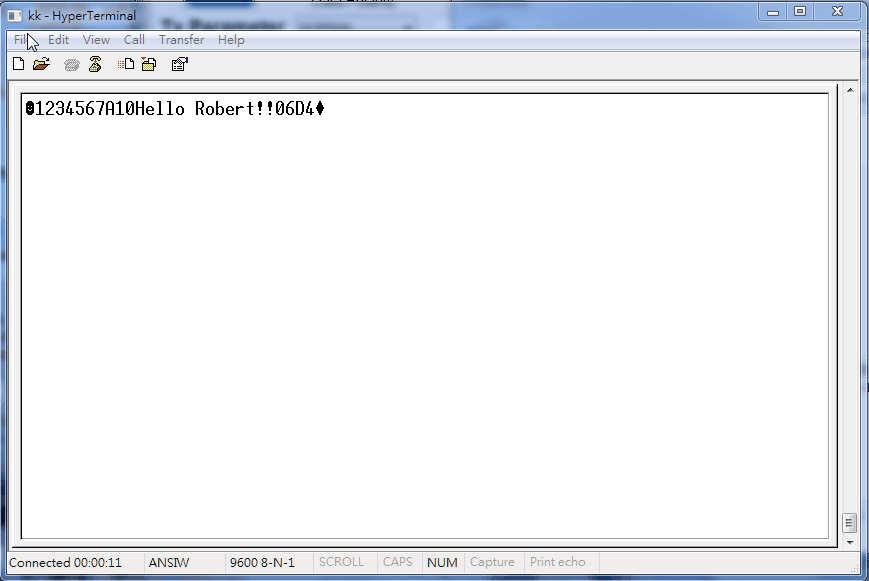
![Command Protocol For example by Hyperterminal AF1234567DHello World.. [A] Pager type Alphanumeric, N=Numeric [F] Data bud rate, F=1200bps, N=512 bps, S=2400bps, if blank= Default 1200bps.](/docs-images/90/101572581/images/11-0.jpg "[1234567] Pager copcode, pager address. [D] Pager tone alert, A for tone A, B for tone B, C for tone C, D for tone D. [Hello World] message word.")
11 Command Protocol For example by Hyperterminal AF DHello World.. [A] Pager type Alphanumeric, N=Numeric [F] Data bud rate, F=1200bps, N=512 bps, S=2400bps, if blank= Default 1200bps. [ ] Pager copcode, pager address. [D] Pager tone alert, A for tone A, B for tone B, C for tone C, D for tone D. [Hello World] message word. Protocol Format Error Respond: If the first character other than A or N --- Invalid Command format1!<cr><lf> capcode fields appear with letter of alphabet --- Invalid Command format2!<cr><lf> capcode <8, > Capcode over range!<cr><lf> message type field appears character out of the ABCD--- "Invalid Command format3!\r\n" message has the invisible character ---"Invalid Command format4!\r\n" For example by Hyperterminal with GACOMP2 protocol 11
12 12
13 GACOMP2 protocol V1.32 This protocol is defined for a POCSAG encoder with RS-232 in baud rate ( 9600,N,8,1 ) of PC. PC send to Transmitter Transmitter command format ( All contents is visible ASCII code exclude the STX and EOT) = STX + Capcode content + Message content + CheckSum + EOT = 02H + AAAAAAAERF + Message content + CCCC + 04H Format Description : Contents are all visible ASCII code value >= 20 Hex except the STX and EOT command STX is 02 Hex code, it is not visible in ASCII code EOT is 04 Hex code, it is not visible in ASCII code Capcode content = AAAAAAAERF (a) AAAAAAA is a 7 digits numeric between representing a pager or RCM receiver capcode (b) E is 0,n,or N represent numeric encoding, and 1,a,or A represent alphanumeric encoding (c) R is RF data rate, where 5 represents 512 bps, 1 represents 1200 bps, and 2 represents 2400 bps (d) F is 0,1,2,3,or 4 defines the function code to be delivered. It is 0 represent the default value for F is 4 when the E value is alphanumeric, and 1 when the E value is numeric Numeric message = 0 to F Hex that transfer to visible ASCII code is 30H to 39H (0 9) and 41H to 45H (A F). Message content = any message you want send out,if you did not carry any message then it will send out a "Tone Only" message output CheckSum(CCCC) is a 4 number of ASCII code include all contents before CheckSum ( STX + Capcode content + Message content ) CheckSum example : Capcode content Message content CheckSum EX 1. Num.1200bps N ABCD 03D8 Description : CheckSum = 3D8H (02H+31H+30H+30H+30H+30H+30H+ 31H+4EH+31H+31H+31H+32H+33H+34H+41H+42H+43H+44H) CCCC = 03D8 (30H,33H,44H,38H) Total contents = 02H N111234ABCD03D8 + 04H EX 2. Alpha 1200bps A11 abcdefghijk
14 Description : CheckSum = 662H (02H+30H+30H+30H+30H+31H+32H+38H+41H+31H +31H+61H+62H+63H+64H+65H+66H+67H+68H+69H+6AH+6BH) CCCC = 0662 (30H,36H,36H,32H) Total contents = 02H A11abcdefghijk H EX3. Num. 512 bps N51 xxx 6A3C Description : CheckSum = 126A3CH ( only use last 4 digits as valid ) CCCC = 6A3C (36H,41H,33H,43H) Transmitter send to PC If command accept to transmitter then transmitter send CCCC + ACK(06H) to PC. the CCCC is check sum of message. if command did not accept to transmitter will not send back CCCC + ACK(06H) within 200 ms. Note: Transmitter encode message must be following two conditions then transmitter will encode all messages and send all messages at one time. 1. PC send message then receive the ACK from transmitter and PC send first byte of next message less than 150mS after last ACK. 2. Transmitter received total messages is less then 15K bytes. Idle Capcode is from to
 1 Alarm contact 1 input 2 Alarm contact 2 input 3 Alarm contact 3 input 4")
15 Also if the NP-14 option for 8 dry alarm contacts The following 8 Pins 2 Rows Header Connector will replace the com1 DB9 position. Table x8 Header connector for 8 contacts alarm input PIN SIGNAL DIRECTION Header 2x8 - View looking into connector (NP-14 side) 1 Alarm contact 1 input 2 Alarm contact 2 input 3 Alarm contact 3 input 4 Alarm contact 4 input 5 Alarm contact 5 input 6 Alarm contact 6 input 7 Alarm contact 7 input 8 Alarm contact 8 input 9-16 Ground Each alarm switch NO to NC, or NC to NO be alarm active. More switch of alarm input information 15


16 Option for external trig wires Part No For Alarm switch or alarm sensor direct connect with wires Option for external trig alarm terminal board Part No For external terminal block 16
 PIN SIGNAL DIRECTION 1 AL1 Alarm 1 in S= Trigger, G=Ground 2 AL2 Alarm 2 in S= Trigger, G=Ground 3 AL3 Alarm 3 in S= Trigger, G=Ground 4 AL4 Alarm 4 in S=")
17 Use ext terminal board into to NP-14 Ext. trig port. Table 1-3. Inside contacts input terminal (8 port) PIN SIGNAL DIRECTION 1 AL1 Alarm 1 in S= Trigger, G=Ground 2 AL2 Alarm 2 in S= Trigger, G=Ground 3 AL3 Alarm 3 in S= Trigger, G=Ground 4 AL4 Alarm 4 in S= Trigger, G=Ground 5 AL5 Alarm 5 in S= Trigger, G=Ground 6 AL6 Alarm 6 in S= Trigger, G=Ground 7 AL7 Alarm 7 in S= Trigger, G=Ground 8 AL8 Alarm 8 in S= Trigger, G=Ground Each contact G-S open to short, or short to open be alarm active. 17


18 The alarm cable can be in/out on side hole of NP-14 18
 PIN SIGNAL DIRECTION RJ-45 - View looking into receptacle (NP-14 side) 1 TD+ 2 TD-")
19 NP-14 Net-Paging System Ethernet IP set up Guide Table 1-4. RJ-45 ETHERNET PORTS (8 pin receptacle) PIN SIGNAL DIRECTION RJ-45 - View looking into receptacle (NP-14 side) 1 TD+ 2 TD- 3 RD+ 4 NA 5 NA 6 RD- 7 NA 8 NA Click Click to install NPort 19

20 Click Next Click Next 20


21 Clock Install Click Finish 21


22 Click your PC start then click Nport Click Click Search 22


23 To find a IP address Click OK Click Yes 23


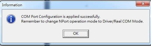
24 Waiting. NPort is ready 24

25 RF/Antenna output RF/Antenna output of BNC The BNC Jack for RF output or for antenna IF RF power under 2 W, the NP-14 antenna can be used by the robber wipe antenna IF RF power over 2W, the NP-14 must use the external antenna., which must be Set the 1.5 meters away from the NP-14 unit to avoid the interference. Folding Antenna The BNC folding antenna for RF power under 2W use only If RF power over 2W and UP must using external antenna. Mount Mount on the wall by screw max 5 mm mm
26 NP-14 NetPage Paging System Specifications Frequency: MHz Synthesized MHz Synthesized Paging format: Pager Baud rate: Message type : Channel Spacing: Modulation: Deviation: Stability: POCSAG. 512bps / 1200bps / 2400bps. ASCII 6.25K / 12.5K / 25K. Frequency Synthesized by USB programming NRZ NFSK, for POCSAG Khz 10ppm. RF output power: 0.1~7 W (programmable) 0.1~4 W (programmable) RF output connector: P/C Interface: BNC female (SMA female option) USB 2.0 and RS bps Ethernet: RJ-45 TCP/IP 10/100M Operation temperature: Power Supply: Size: Model Weight: -25 C ~ 70 C DC 12V 1A(Minimum) 120 mm X 110 mm X 25 mm. 0.8KGs. include AC 100~240 to DC 12V 2A switching power adapter. Notes: Specifications are subject to change without notice CCW END ---- May
On-site Wireless Paging System (POCSAG) Operation Manual. M-909X 8 individual buttons plus 1 group call button. M-916X 16 individual buttons
 Operation Manual. M-909X 8 individual buttons plus 1 group call button. M-916X 16 individual buttons") On-site Wireless Paging System (POCSAG) M-909X 8 individual buttons plus 1 group call button M-916X 16 individual buttons Operation Manual 1 INTRODUCTION The M-909X and M-916X on-site paging system are
On-site Wireless Paging System (POCSAG) M-909X 8 individual buttons plus 1 group call button M-916X 16 individual buttons Operation Manual 1 INTRODUCTION The M-909X and M-916X on-site paging system are
PRODUCT MANUAL VHF & UHF Pocket Paging Transmitter. Version 1.00 April 2017
 11-85-0000 VHF & UHF Pocket Paging Transmitter PRODUCT MANUAL Version 1.00 April 2017 Copyright 2017 Sea Air and Land Communications Ltd. All rights reserved. P a g e 1 Salcom Product Documentation This
NC369 Paging Transmitter Installation Instructions
 NC369 Paging Transmitter Installation Instructions IL888 Section E Rev. 6-03/2010 OVERVIEW TekTone s digital paging system can be used to transmit text and numeric messages directly to individual pocket
Response Plus & Link Paging Systems Data Sheet
 Response Plus & Link Paging Systems Data Sheet The Response Paging System offers the latest innovations in wireless paging and monitoring. It s a cost effective and flexible system that provides the ability
SMARTALPHA RF TRANSCEIVER
 SMARTALPHA RF TRANSCEIVER Intelligent RF Modem Module RF Data Rates to 19200bps Up to 300 metres Range Programmable to 433, 868, or 915MHz Selectable Narrowband RF Channels Crystal Controlled RF Design
MPR kHz Reader
 MPR-5005 Page 1 Doc# 041326 MPR-5005 125kHz Reader Installation & Operation Manual - 041326 MPR-5005 Page 2 Doc# 041326 COPYRIGHT ACKNOWLEDGEMENTS The contents of this document are the property of Applied
MICROWAVE FREQUENCY SYNTHESIZER QP-FSPLL USER MANUAL
 MICROWAVE FREQUENCY SYNTHESIZER QP-FSPLL-0040-01 USER MANUAL The QP-FSPLL-0040-01 is a low-phase noise wideband synthesizer operating from 50 MHz to 40 GHz with a nominal output power of +15 dbm. The synthesizer
G3P-R232. User Manual. Release. 2.06
 G3P-R232 User Manual Release. 2.06 1 INDEX 1. RELEASE HISTORY... 3 1.1. Release 1.01... 3 1.2. Release 2.01... 3 1.3. Release 2.02... 3 1.4. Release 2.03... 3 1.5. Release 2.04... 3 1.6. Release 2.05...
R5 RIC Quickstart R5 RIC. R5 RIC Quickstart CONTENTS. Saab TransponderTech AB. Appendices. Project designation. Document title
 Appendices 1 (10) Project designation R5 RIC Document title CONTENTS 1 Installation... 2 1.1 Connectors... 2 1.1.1 Power... 2 1.1.2 Video... 2 1.1.3 Sync... 3 1.1.4 RS232/ARP/ACP... 3 1.1.5 Radar data...
DDS-PLL SYNTHESIZER DPL-2.5GF USER S MANUAL DIGITAL SIGNAL TECHNOLOGY, INC.
 DDS-PLL SYNTHESIZER DPL-2.5GF USER S MANUAL DIGITAL SIGNAL TECHNOLOGY, INC. 1-7-3, HIGASHI BENZAI, ASAKA CITY SAITAMA 351-22 JAPAN TEL : 81-48-468-694 FAX : 81-48-468-621 http://www.dst.co.jp/en 1 DPL-2.5GF
VBRC 5. Radio Communicator. Installer Manual
 VBRC 5 Radio Communicator Installer Manual 10 / 10 / 2013 CONTENT 1. INTRODUCTION...3 2. SYSTEM STRUCTURE...3 3. SYSTEM PROGRAMMING WITH PC SOFTWARE...5 4. TROUBLESHOOTING...6 5. FIRMWARE UPGRADE...7 6.
Back to. Communication Products Group. Technical Notes. Local/Remote Control, 9300 Series
 Back to Communication Products Group Technical Notes 25T001 Local/Remote Control, 9300 Series MITEQ TECHNICAL NOTE 25T001 MAY 1995 REV G 1.0 LOCAL/REMOTE SELECTION LOCAL/REMOTE CONTROL 9300 SERIES CONVERTER
2W UHF MHz Radio Transceiver
 2W UHF410-470 MHz Radio Transceiver Specification Copyright Javad Navigation Systems, Inc. February, 2006 All contents in this document are copyrighted by JNS. All rights reserved. The information contained
PRX4SERL Four Zone Receiver Decoder
 PRX4SERL Four Zone Receiver Decoder Operating Manual Microframe Corporation 604 S. 12 th Street Broken Arrow, OK 74012 Tel: (918) 258-4839 Toll Free: 1-800-635-3811 Website: www.microframecorp.com E-mail:
VBRC 4. Radio Communicator. Installer Manual
 VBRC 4 Radio Communicator Installer Manual 17 December 2014 CONTENT 1. INTRODUCTION...3 2. SYSTEM STRUCTURE...3 3. SYSTEM PROGRAMMING WITH PC SOFTWARE...5 4. TROUBLESHOOTING...6 5. FIRMWARE UPGRADE...7
Stensat Transmitter Module
 Stensat Transmitter Module Stensat Group LLC Introduction The Stensat Transmitter Module is an RF subsystem designed for applications where a low-cost low-power radio link is required. The Transmitter
Applications. Operating Modes. Description. Part Number Description Package. Many to one. One to one Broadcast One to many
 RXQ2 - XXX GFSK MULTICHANNEL RADIO TRANSCEIVER Intelligent modem Transceiver Data Rates to 100 kbps Selectable Narrowband Channels Crystal controlled design Supply Voltage 3.3V Serial Data Interface with
POCSAG Paging via the TM8100
 POCSAG Paging via the TM8100 Introduction Technical Note TN-NSC080 TM8100 POCSAG Paging 5 December 2003 The TM8100 is able to support POCSAG modulation via the use of an external Encoding device. The modulation
Quick-Start Guide. M7 Series DATA RADIO MODEM
 Quick-Start Guide M7 Series DATA RADIO MODEM Raveon Technologies Corporation 2461 Impala Drive Carlsbad, CA 92010 - USA Phone +1-760-444-5995 www.raveon.com www.ravtrack.com 1 This is a quick-start guide
2320 cousteau court
 Technical Brief AN139 Rev C22 2320 cousteau court 1-760-444-5995 sales@raveon.com www.raveon.com RV-M7 GX with TDMA Data By John Sonnenberg Raveon Technologies Corporation Overview The RV-M7 GX radio modem
CDR-915 Data Radio Module INTEGRATOR S GUIDE
 CDR-915 Data Radio Module Coyote DataCom, Inc. 3941 Park Drive, Suite 20-266, El Dorado Hills, CA 95762 Tel. 916-933-9981 Fax 916-913-0951 www.coyotedatacom.com TABLE OF CONTENTS General Information and
RF Wireless Serial Device Server
 RF-SDS RF Wireless Serial Device Server The RF-SDS subassembly is a radio transceiver acting as a Serial Device Server, which externally connects a remote serial RF transceiver to an Ethernet network (TCP/IP).
IntelPage 5W (POCSAG) Transmitter
 Transmitter") A division of NESS CORPORATION PTY LTD IntelPage 5W (POCSAG) Transmitter INSTALLATION MANUAL IntelPage 5W (POCSAG) Transmitter Installation Manual v1.2 1. Contents 1. Contents... 1 2. Equipment List...
A division of NESS CORPORATION PTY LTD IntelPage 5W (POCSAG) Transmitter INSTALLATION MANUAL IntelPage 5W (POCSAG) Transmitter Installation Manual v1.2 1. Contents 1. Contents... 1 2. Equipment List...
Multi-Channel RS-232 Serial RF Transceiver
 RF-232 Multi-Channel RS-232 Serial RF Transceiver The RF-232 subassembly is a multi-channel serial radio transceiver. This device accepts and outputs standard serial data at one of three selectable data
Guardian and DL3282 Modem Interface Technical Service Application Note
 Guardian and DL3282 Modem Interface Technical Service Application Note OVERVIEW The following document is designed to provide information for the implementation of the Guardian Wireless Modem/Analog Radio
ST600 TRANSMITTER OPERATING INSTRUCTIONS
 ST600 TRANSMITTER OPERATING INSTRUCTIONS 1892 1273 These operating instructions are intended to provide the user with sufficient information to install and operate the unit correctly. The Wood and Douglas
SV613 USB Interface Wireless Module SV613
 USB Interface Wireless Module SV613 1. Description SV613 is highly-integrated RF module, which adopts high performance Si4432 from Silicon Labs. It comes with USB Interface. SV613 has high sensitivity
AT-XTR-7020A-4. Multi-Channel Micro Embedded Transceiver Module. Features. Typical Applications
 AT-XTR-7020A-4 Multi-Channel Micro Embedded Transceiver Module The AT-XTR-7020A-4 radio data transceiver represents a simple and economical solution to wireless data communications. The employment of an
SonoLab Echo-I User Manual
 SonoLab Echo-I User Manual Overview: SonoLab Echo-I is a single board digital ultrasound pulse-echo solution. The system has a built in 50 volt high voltage generation circuit, a bipolar pulser, a transmit/receive
SMR5000F. User Manual. Smart Radio Data Repeater. Web Site: P.N.: Book 092
 SMR5000F Smart Radio Data Repeater User Manual ISRAEL Office: Email: info@kpsystems.com PO Box 42, Tefen Industrial Park, Tefen 24959 Tel: 972-4-987-3066 / Fax: 972-4-987-3692 USA Office: KP ELECTRONICS,
SRT PAGING & DATA RECEIVER MANUAL
 SRT PAGING & DATA RECEIVER MANUAL Covering the following: SRT150R, SRT280R, SRT320R, SRT450R & SRT950R CONTENTS 1.0 INTRODUCTION 1.1 APPLICATIONS 1.2 SPECIFICATION 1.3 RS232 SERIAL PORT 1.4 PROGRAMMING
Ultrasonic Multiplexer OPMUX v12.0
 Przedsiębiorstwo Badawczo-Produkcyjne OPTEL Sp. z o.o. ul. Morelowskiego 30 PL-52-429 Wrocław tel.: +48 (071) 329 68 54 fax.: +48 (071) 329 68 52 e-mail: optel@optel.pl www.optel.eu Ultrasonic Multiplexer
Signal Forge. Signal Forge 1000 TM Synthesized Signal Generator. Flexible Design Enables Testing of RF and Clock-driven Systems.
 Signal Forge TM Signal Forge 1000 TM Synthesized Signal Generator L 8.5 W 5.4 H 1.5 Flexible Design Enables Testing of RF and Clock-driven Systems The Signal Forge 1000 combines a 1 GHz frequency range
Studio Broadcast System
 SET UP and USE 1. REGULATORY AND COMPLIANCE STATEMENTS... 3 2. OVERVIEW 2.1 Core Performance Targets 2.2 Specifications 2.3 System Components 2.4 System Block Diagram 3. BP24 UWB BODY PACK TRANSMITTER...
Guest Receiver INDEX INDEX. Guest Paging System... 1 Guest Receiver... 1 Desktop Transmitter...3. Transmitting Enhancement TX-125 series...
 INDEX Guest Paging System... 1 Guest Receiver... 1 Desktop Transmitter...3 ALL-IN ONE Guest Paging System... 4 Wireless Calling System... 6 NURSE CALL SYSTEM... 8 EMERGENCY CALL System... 10 Personal Caring
13. OP-03 RS-232C SERIAL INTERFACE
 This document hosted by: www.oldwillknottscales.com 13. OP-03 RS-232C SERIAL INTERFACE This interface allows the HC-i series to be connected with a multifunction printer or a personal computer. The OP-03
RF7129 Ultra-low power Tranceiver module V2.0
 1. General RF7129 series is a low cost, ultra-low power, high performance transparent two way semi-duplex GFSK transceiver with operation at 433/470/868/915 Mhz. It integrates with high speed MCU from
S O P H I S T I C A T E D A U T O M A T I O N
 S O P H I S T I C A T E D A U T O M A T I O N Introduction Cost-effective Radio modems to any serial communication application Low power models, different frequency ranges RS232 / / RS422 / 5V TTL interface
VNS2500. Wireless Public Address Controller. User's Manual / Installation Guide. Version 1.26
 VNS2500 Wireless Public Address Controller User's Manual / Installation Guide Version 1.26 Visiplex, Inc. 2009 VNS2500 Wireless PA & Mass Notification Controller Copyright The product described in this
SIMREX Corporation Your Trusted Wireless Solution Provider
 SIMSYNC Instruction Manual Traffic Controller Time Synchronization System Firmware Release 1.7 SIMREX MAN.SIMSYNC, Rev 8.0 MARCH 2006 Your Trusted Wireless Solution Provider www.simrex.com Introduction
INSTRUCTION MANUAL. IBRit - rf1 - usb PC - Station for wireless Data transmission. M e s s t e c h n i k. Messtechnik GmbH & Co.
 M e s s t e c h n i k INSTRUCTION MANUAL PC - Station for wireless Data transmission Document No. : D1F604 001 Version : April 2006 Copyright : IBR Messtechnik GmbH & Co. KG Contents 1. Introduction 1.1
QuidoDuplex. Two-state signal over-ethernet transmission set based on I/O module Quido. 12. July 2017 w w w. p a p o u c h. c o m
 Two-state signal over-ethernet transmission set based on I/O module Quido 12. July 2017 w w w. p a p o u c h. c o m Q uidoduplex Datasheet Created: 3/16/2006 Last update: 7/12/2017 1:28 PM Number of pages:
VHF AND UHF TRANSMITTER PRODUCT MANUAL. Version 1.01 August Copyright 2017 Sea Air and Land Communications Ltd. All rights reserved.
 12-62-0000 VHF AND UHF TRANSMITTER PRODUCT MANUAL Version 1.01 August 2017 Copyright 2017 Sea Air and Land Communications Ltd. All rights reserved. P a g e 1 Salcom Product Documentation This document
Technical datasheet. The DTXF-xxx supports South Korean ISM band, 424.7MHz, 447.3MHz and Japanese 429MHz as well as European MHz.
 DTXF-xxx Narrow band single channel FSK transmitter The DTXF-xxx series, a narrow band module with 12.5KHz channel spacing, is a high performance transmitter designed for use in industrial & commercial
Maintenance Manual. MTD SERIES 900 MHz, 10-WATT, DATA ONLY MOBILE RADIO. Mobile Communications LBI TABLE OF CONTENTS
 Mobile Communications MTD SERIES 900 MHz, 10-WATT, DATA ONLY MOBILE RADIO TABLE OF CONTENTS RF BOARD............................... LBI-38545 AUDIO BOARD............................ LBI-38546 LOGIC BOARD............................
HR1200. Version 1.00 ATIM RADIOCOMMUNICATION 1/11
 HR1200 Version 1.00 ATIM RADIOCOMMUNICATION 1/11 Contact Information ATIM RADIOCOMMUNICATION Les guillets 38250 Villard de Lans France Tel : +33 (0)4 76 95 50 65 Fax: +33 (0)4 76 95 50 64 Web : www.atim.com
Home Automation, Inc. Omnistat2. RC-1000 and RC-2000 Communicating Thermostat. Serial Protocol Description
 Home Automation, Inc. Omnistat2 RC-1000 and RC-2000 Communicating Thermostat Serial Protocol Description This document contains the intellectual property of Home Automation, Inc. (HAI). HAI authorizes
Operation Manual [Version 3.09]
![Operation Manual [Version 3.09]](/thumbs/89/100538569.jpg "Operation Manual [Version 3.09]") Sub-1GHz to Internet P-900 IoT Station. Operation Manual [Version 3.09] Connect POCSAG to Internet by WIFI and receive by smart phone. Table of Contents 1. Introduction... 2 2.. Apparent of P-900 IoT station...
Sub-1GHz to Internet P-900 IoT Station. Operation Manual [Version 3.09] Connect POCSAG to Internet by WIFI and receive by smart phone. Table of Contents 1. Introduction... 2 2.. Apparent of P-900 IoT station...
Signal Forge. Signal Forge 1000 TM Synthesized Signal Generator. Digital and RF Tester with 1 GHz Range. Key Features
 Signal Forge TM Signal Forge 1000 TM Synthesized Signal Generator L 8.5 W 5.4 H 1.5 Digital and RF Tester with 1 GHz Range The Signal Forge 1000 combines a 1 GHz frequency range with three dedicated outputs
MODEL FVP-44. Setup & Programming Manual
 MODEL FVP-44 Rolling Code Encryption board for VX-450 / VX-4500 / VX-4600 VERTEX/STANDARD RADIOS Setup & Programming Manual Installation: Running the installation program, CimarronQuikWareSetupFVP44.EXE,
TC-2000A Universal Pager Tester
 TC-2000A Universal Pager Tester Product Description The TC-2000A Universal Pager Tester combines all of the test features required for pager testing within a single unit. Designed for R & D, manufacturing,
Mastr III P25 Base Station Transmitter Tune-up Procedure
 Mastr III P25 Base Station Transmitter Tune-up Procedure 1. Overview The Mastr III Base Station transmitter alignment is performed in several steps. First, the Transmit Synthesizer module is aligned to
RF ISM Transparent Transceiver Module V4.0
 RF7020-27 ISM Transparent Transceiver Module V4.0 Overview: RF7020-27 is highly integrated semi-duplex medium power transceiver module with high speed MCU and high performance RF IC. Utilizing high efficiency
PYRAMID 915MHZ WIRELESS RF TRANSMITTER & REPEATER USER GUIDE. Table of Contents. Overview Installation Setup Specifications...
 Table of Contents Overview................................... 1 Installation.................................. 1 Setup...................................... 2 Specifications..............................
IDA 4 XM V 1.X. Installation and configuration of IDA 4 XM User Manual
 IDA 4 XM V 1.X Installation and configuration of IDA 4 XM User Manual IMPORTANT SAFETY INSTRUCTIONS - Switch the device s power off before any maintenance operation (changing the CU card, etc.) - The 24V
HURRICANE Radio Modem. FULL DUPLEX Radio MODEM
 FULL DUPLEX Radio MODEM Direct Cable Replacement Range 2KM RS232 / RS485 / USB Host Data Rates up to 38,400 Baud RF Data Rates to 115200Kbps Waterproof IP68 Enclosure 8 User Selectable Channels CE Compliant
TRANSCEIVER FSK. Version: 434 MHz Band / 868 MHZ Band / Code: / A
 TRANSCEIVER FSK Version: 434 MHz Band / 868 MHZ Band / Code: 3-2000519 / 3-2000519A DESCRIPTION: The 3-2000519 and 3-2000519A modules are fully programmable multichannel PLL based FSK transceivers, with
1 What s in the shipping package?
 SST 900B 900 MHz RS 232/RS 485 Wireless Modem Quick Start Guide 1 What s in the shipping package? SST-900B Wireless Modem CA-0910 Quick Start CD 3dBi 900M Hz Antenna Guide 2 External switch introduction
PTX-150 DIRECT DIGITAL PAGING TRANSMITTER
 DIRECT DIGITAL PAGING TRANSMITTER Sonik Technologies Corporation User Manual Version C2 October 2000 Sonik Technologies Corporation 2310 Cousteau Ct Vista, CA 92083 Ph: 760-536-1000 Fax: 760-536-1024 email:
USB Multifunction Arbitrary Waveform Generator AWG2300. User Guide
 USB Multifunction Arbitrary Waveform Generator AWG2300 User Guide Contents Safety information... 3 About this guide... 4 AWG2300 specifications... 5 Chapter 1. Product introduction 1 1. Package contents......
FastLink TM. Network. Operation and Installation Manual
 FastLink TM Network Operation and Installation Manual C6570 C6571 C6571S C6572 C6572S C6573S Store and Forward Controller Network Store and Forward Controller Service Store and Forward Controller Network
satech SynchroStar GPS 200 Series
 satech SynchroStar GPS 200 Series KEY BENEFITS Designed with high quality oscillator OCXO the device is characterized by superior frequency stability and improved holdover performance that allows maintaining
HC SI4463 Wireless Serial Module
 HC-12 433 SI4463 Wireless Serial Module Description: HC-12 wireless serial port communication module is a new-generation multichannel embedded wireless data transmission module. Its wireless working frequency
Specification Sym Notes Minimum Typical Maximum Units 900 MHz Operating Frequency Range MHz
 900 MHz FHSS DNT90/Ethernet Gateway Optional 128-Bit AES Encryption Point-to-point, Point-to-multipoint or Store and Forward Operation 158 mw EIRP 900 MHz Transmitter Power 10/100Base-T Auto-sensing Ethernet
Analog and POCSAG digital radio pager tester PS 622 User Manual
 Analog and POCSAG digital radio pager tester PS 622 User Manual Oelmann Elektronik GmbH, 2017 General Notes The PS 622 is the original portable device allows functional tests on analog and digital (POCSAG)
EVDP610 IXDP610 Digital PWM Controller IC Evaluation Board
 IXDP610 Digital PWM Controller IC Evaluation Board General Description The IXDP610 Digital Pulse Width Modulator (DPWM) is a programmable CMOS LSI device, which accepts digital pulse width data from a
ISTATION-N (Integration Station) User Manual
 User Manual") ISTATION-N (Integration Station) User Manual HME Wireless, Inc Customer Service 800.925.8091 1400 Northbrook Parkway Suite #320 Suwanee, GA 30024 HME 800.925-8091 Integration Station Serial Transmitter
ISTATION-N (Integration Station) User Manual HME Wireless, Inc Customer Service 800.925.8091 1400 Northbrook Parkway Suite #320 Suwanee, GA 30024 HME 800.925-8091 Integration Station Serial Transmitter
Evaluation Kits EVA 100 and EVA 105
 Evaluation Kits EVA 100 and EVA 105 User Manual V1.7 April 2007 Revision History The following major modifications and improvements have been made to the first version of the document (EVA 100 User Manual
SMS control unit for SRK transmitters
 SMS control unit for SRK transmitters Ver 1.00 13 February 2014 Initial release Ver 1.01 14 February 2014 Updated POWER and GAIN syntax Ver 1.02 13 April 2014 Added photo Added TX ON, TX OFF, AUX ON an
era, eric, era-lora, eric-lora & eric-sigfox Evaluation Board with GNSS
 This board can be used for the evaluation and range testing of the following LPRS RF Modules: era400, era900, eric4, eric9, era-lora, eric-lora and eric-sigfox. The board is provided with a u-blox GNSS
M7 Over-The-Air Protocol. Overview. Technical Brief AN187 Rev A1
 Technical Brief AN187 Rev A1 M7 Over-The-Air Protocol By John Sonnenberg Raveon Technologies Corp Overview The M7 GX series of GPS transponders may be directly connected to a Garmin GPS 152H navigation
KAPPA M. Radio Modem Module. Features. Applications
 KAPPA M Radio Modem Module Features Intelligent RF modem module Serial data interface with handshake Host data rates up to 57,600 baud RF Data Rates to 115Kbps Range up to 500m Minimal external components
2F. No.25, Industry E. 9 th Rd., Science-Based Industrial Park, Hsinchu, Taiwan Application Note of OGM220, AN001 V1.8
 Application Note of OGM220, AN001 V1.8 1.0 Introduction OGM220 series is a dual channels NDIR module having a digital output directly proportional to CO2 concentration. OGM220 is designed for multi-dropped
Catalog
 - 1 - Catalog 1. Overview...- 3-2. Feature... - 3-3. Application...- 3-4. Block Diagram...- 3-5. Electrical Characteristics... - 4-6. Operation... - 4-1) Power on Reset... - 4-2) Sleep mode... - 4-3) Working
The "FISH" Quad Hand Sensor
 The "FISH" Quad Hand Sensor Physics and Media Group MIT Media Laboratory 20 Ames Street E15-022 Cambridge, Mass 02139-4307 (617) 253-2383 phm@media.mit.edu ** U S E R S G U I D E ********* TABLE OF CONTENTS
LBI Installation & Operation
 Installation & Operation EDACS Power Monitor Unit ericssonz CONTENTS TABLE OF CONTENTS Page INTRODUCTION... 6 DESCRIPTION... 6 APPLICATION NOTES... 7 VAX SITE CONTROLLER COMPUTER... 7 APPLICATION SOFTWARE
Phone:
 Email: Support@signalforge.com Phone: 512.275.3733 Web: www.signalforge.com Customer Service Email: Sales@signalforge.com Phone: 512.275.3733 Fax: 512.275.3735 Address: Signal Forge, LLC 2115 Saratoga
RF1276 Long Distance Transceiver module V2.0
 1. General RF1276 series is a low cost, ultra-low power, high performance transparent two way semi-duplex LoRa modulation transceiver with operation at 169/433/868/915 Mhz. It integrates with high speed
EULAMBIA ADVANCED TECHNOLOGIES LTD. User Manual EAT-EOM-CTL-2. Alexandros Fragkos
 EULAMBIA ADVANCED TECHNOLOGIES LTD User Manual Alexandros Fragkos (alexandros.fragkos@eulambia.com) 11/28/2016 28/11/2016 User Manual User Manual 28/11/2016 Electro-Optic Modulator Bias Control Unit v2.0
Interface Genius Modem Instruction Manual v1.2.4
 Interface Genius Modem Instruction Manual v1.2.4 Interface Genius Modem is a USB / LAN controlled SO2R radio interface remote radio modem. It is designed to be controlled by a Windows application, and
TC-3000C Bluetooth Tester
 TC-3000C Bluetooth Tester Product Instructions TC-3000C Bluetooth Tester is able to analyze the data of every packet that is transmitted to the upper application protocol layer using the protocol stack,
RF4432 wireless transceiver module
 1. Description www.nicerf.com RF4432 RF4432 wireless transceiver module RF4432 adopts Silicon Lab Si4432 RF chip, which is a highly integrated wireless ISM band transceiver. The features of high sensitivity
20 CHANNELS DIGITAL DELAY GENERATOR
 NUT 063 Ed. 2.2 September 2015 User's Manual MODEL 745-20C 20 CHANNELS DIGITAL DELAY GENERATOR 20 independent delay channels 100 ps delay resolution (1 ps option) 10 seconds delay range Adjustable output
HL 670 Data / Impulse Transmitter set User Manual. Version 07/2010
 HL 670 Data / Impulse Transmitter set User Manual Version 07/2010 1. Global The Set HL670 is ideal for transferring Timing Data and Impulses. Its 500mW emitting power and its licence free frequency range
Appendix A. Datum Systems PSM-2100/512 Satellite Modem. Technical Specification
 Appendix A Datum Systems PSM-2100/512 Satellite Modem Technical Specification PSM-2100 and PSM-512 VSAT / SCPC - Modem Specification Revision History Rev 1.0 6-15-97 Preliminary Release. Rev 1.1 10-10-97
DRF7020D13 13dBm ISM RF Transceiver Module
 3dBm ISM RF Transceiver Module V2.2 Features Application GFSK transceiver Module 433Mhz ISM frequency band 9.6K bps FSK data rate Multiple channels 3dBm Max. output power Baud rate configurable 256 bytes
Instruction Sheet UPS SERIES. Serial Control Protocol. I Rev E
 Instruction Sheet UPS SERIES Serial Control Protocol I-00341 Rev E (THIS PAGE INTENTIONALLY LEFT BLANK) Page 1 TABLE OF CONTENTS 1 Protocol Overview...3 1.1 Signal characteristics...3 1.2 Primary DB9 Pin
Using the 9XR Pro for More than Eight Channels
 Appendix B Using the 9XR Pro for More than Eight Channels Introduction In stock form, with a module such as the FrSky DJT or OrangeRx DSMX/DSM2 installed, the Turnigy 9XR Pro transmitter can control a
Low Power with Long Range RF Module DATASHEET Description
 Wireless-Tag WT-900M Low Power with Long Range RF Module DATASHEET Description WT-900M is a highly integrated low-power half-'duplex RF transceiver module embedding high-speed low-power MCU and high-performance
RF1212 RF1212 Ultra-low Power ISM Transceiver Module V2.0
 RF1212 Ultra-low Power ISM Transceiver Module V2.0 Application: Features: Home automation Security alarm Telemetry Automatic meter reading Contactless access Wireless data logger Remote motor control Wireless
JZ878 RF Data Radio. User s Manual
 JZ878 RF Data Radio User s Manual SHEN JIZHUO TECHNOLOGY CO., LTD TEL: +86-755-83304518 / 83308451/81353151 FAX: +86-755-83302824 Address: NO.813,212BLD,Tairan Tech Park, Futian District Shenzhen China
GPS Time and Frequency Reference Receiver
 $ GPS Time and Frequency Reference Receiver Symmetricom s 58540A GPS time and frequency reference receiver features: Eight-channel, parallel tracking GPS engine C/A Code, L1 Carrier GPS T-RAIM satellite
Remote Site Monitoring
 Remote Site Monitoring FEATURES AT A GLANCE Codan Radio Communications now offers Remote Site Monitoring options that provide live site information, giving you the power to respond intelligently to communications
Eight channel remote relay card. Total solder points: 277 Difficulty level: beginner advanced K8056 ILLUSTRATED ASSEMBLY MANUAL
 Eight channel remote relay card This relay card can be used in several ways : stand alone card, addressed by switches or open collector outputs or remote controlled through RS232. Total solder points:
Revision WI.232FHSS-25-FCC-R and RK-WI.232FHSS-25-FCC-R USER S MANUAL
 Revision 1.0.3 WI.232FHSS-25-FCC-R and RK-WI.232FHSS-25-FCC-R USER S MANUAL RADIOTRONIX, INC. WI.232FHSS-25-FCC-R/ RK-WI.232FHSS-25-FCC-R USER S MANUAL Radiotronix 905 Messenger Lane Moore, Oklahoma 73160
PC Tune PC Tune Test Procedures for 5100 Series Portable Radios
 PC Tune PC Tune Test Procedures for 5100 Series Portable Radios Part Number 002-9998-6513014 August 2008 Copyright 2006, 2007, 2008 by EFJohnson Technologies The EFJohnson Technologies logo, PC Configure,
WTPCT-M. eeder. Pulse Counter/Timer Module. Technologies FEATURES SPECIFICATIONS DESCRIPTION. Weeder Technologies
 eeder Technologies 90-A Beal Pkwy NW, Fort Walton Beach, FL 32548 www.weedtech.com 850-863-5723 Pulse Counter/Timer Module FEATURES Reads frequency from 0.50000 to 1,400,000 Hz using 5 digit resolution
USB-UART RADIO MODULE(WM11TR_ L_02_USB)
") Documents Version: 2.05 Document No. 2012-0046-E Copyright is reserved by Rping Group Limited (2008-2015) USB-UART RADIO MODULE(WM11TR_ L_02_USB) USER GUIDE 82469790 Index Documents Version: 2.05... 1
Documents Version: 2.05 Document No. 2012-0046-E Copyright is reserved by Rping Group Limited (2008-2015) USB-UART RADIO MODULE(WM11TR_ L_02_USB) USER GUIDE 82469790 Index Documents Version: 2.05... 1
3 GHz Carrier Backhaul Radio. Model: AF-3X. Tel: +44 (0) Fax: +44 (0) LINK GPS MGMT DATA DATA
 Fax: +44 (0) LINK GPS MGMT DATA DATA") LINK GPS MGMT DATA DATA MGMT GPS LINK 3 GHz Carrier Backhaul Radio Model: AF-3X LINK GPS MGMT DATA 3 GHz Carrier Backhaul Radio Model: AF-3X LINK GPS MGMT DATA DATA MGMT GPS LINK Introduction Thank you
LINK GPS MGMT DATA DATA MGMT GPS LINK 3 GHz Carrier Backhaul Radio Model: AF-3X LINK GPS MGMT DATA 3 GHz Carrier Backhaul Radio Model: AF-3X LINK GPS MGMT DATA DATA MGMT GPS LINK Introduction Thank you
MDS SD4 Software-Controlled Digital Communications Firmware Release 1.x.x
 MDS SD4 Software-Controlled Digital Communications Start-Up Guide Firmware Release 1.x.x MDS 05-4669A01, Rev. A December 2007 OPERATIONAL & SAFETY NOTICES RF Exposure Concentrated energy from a directional