F82 INVERTER SERVICE MANUAL 6137 UNION SWITCH & SIGNAL DIVISION AMERICAN STANDARD INC./ SWISSVALE, PA PART NUMBER N CONTENTS PAGE
|
|
|
- Hilary Lyons
- 5 years ago
- Views:
Transcription
1 F82 INVERTER PART NUMBER N SERVICE MANUAL 6137 CONTENTS SECTION I II III IV v VI, PAGE GENERAL INFORMATION INTRODUCTION DESCRIPTION SPECIFICATIONS 1 FUNCTIONAL DESCRIPTION FUNCTIONAL OPERATION CIRCUIT DESCRIPTION 2 INSTALLATION MOUNTING INSTRUCTIONS ELECTRICAL CONNECTIONS 4 MAINTENANCE FIELD MAINTENANCE SHOP MAINTENANCE MECHANICAL INSPECTION ELECTRICAL TESTING 5 APPLICATION 6 PARTS LIST 10 June, 1981 B-8/ UNION SWITCH & SIGNAL DIVISION AMERICAN STANDARD INC./ SWISSVALE, PA PRINTED IN USA
2 i..
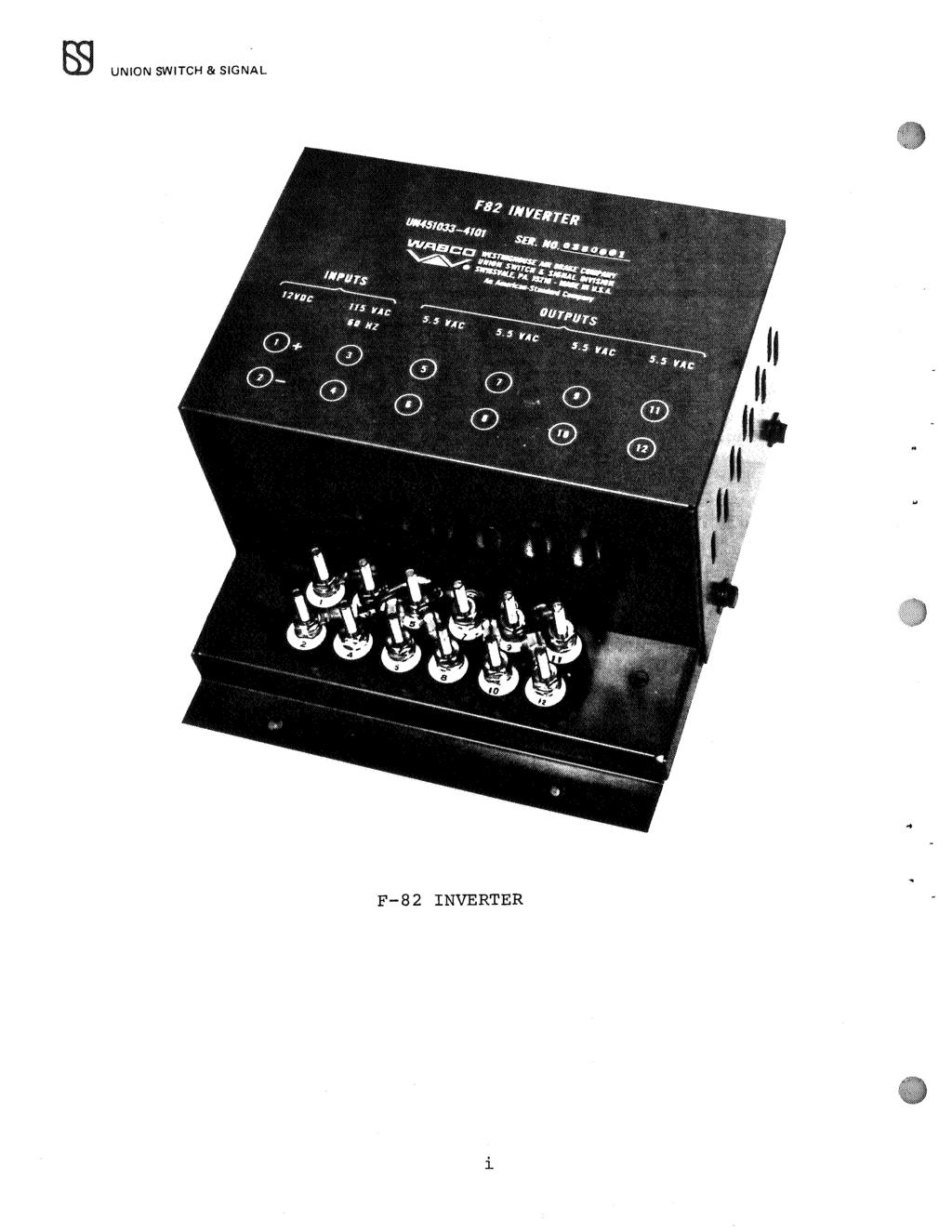
3 UNION SWITCH & SIGNAL ffi SECTION I GENERAL INFORMATION 1.1 Introduction This Service Manual describes the F-82 Inverter and provides instructions for installation and maintenance. 1.2 Description The F-82 Inverter is specifically designed for use in type "C" track circuit applications and is used to convert direct current into alternating current at high efficiency. Essentially, the circuit consists of a solid state astable multivibrator driving several stages of power amplification and a coupling transformer. 1.3 Specifications Electrical Characteristics Power Requirements: Normal Operation Voltage volts ac Current - 1 ampere, maximum Standby Operation Voltage - nominal 12-volt input, storage battery, or regulated power supply ( volts de) Current - 10 amperes maximum Power Output: Normal Operation Four, 5.5 volt R.M.S. sine amperes each secondary. Standby Operation Four, 5.5 volt R.M.S. square amperes each secondary. Reverse battery protection built-in Physical Characteristics Overall dimensions: Length, 12 inches Width, 10 3/4 inches Height, 6 inches Weight, 23 pounds (approximate) Operating Temperature -40 C C 6137, p. 1
4 ffi UNION SWITCH & SIGNAL 2.1 Functional Operation SECTION II FUNCTIONAL DESCRIPTION The F-82 Inverter is designed for use as a standby power supply or as a sole power source for type "C" track circuit equipment. During normal operation of the inverter, the "steering" relay is energized and it applies 120 volts as power to the primary winding of the transformer producing four 5.5 volt sinusoidal secondary outputs. During power failure or low line voltage the "steering" relay is de-energized, automatically removing the ac source from its intended primary winding and connecting the transistorized inverter circuit to the 12 volt ac standby source. The type "C" track circuit is an ac-dc circuit designed to detect the presence of a train. A de relay is connected across an ac power source (F-82 Inverter) which is connected to the rails. A track rectifier is also connected across the rails at the opposite end of the track circuit providing a half wave shunt across the track circuit relay coil. The rectified ac signal energizes the de relay. When a train occupies the track within the track circuit limits, it shunts the recifier and the result is a lower power ac wave applied to the de relay. This action causes the relay to become de-energized. 2.2 Circuit Description The circuit diagram for the F-82 Inverter is shown in Fig. 1. During normal operation when 120 volt ac power is present at the "AC Input" terminals, relay 1 is energized removing power from the inverter circuit and applying voltage to the 120 volt winding of the transformer producing four 5.5 volt R.M.S. sinusoidal outputs. When this voltage is not present, for example during a power failure, relay 1 becomes de-energized open circuiting the 120 volt winding of the transformer and connecting the 12 volt de back up source to the inverter. The inverter circuit is made up of an integrated circuit astable multivibrator IC1 whose frequency of oscillation is determined by C1 and R1. The complimentary outputs of this multivibrator are amplified through transistors Q1 and Q2 to supply the base drive to transistors Q3 and Q4 which are connected in a push pull arrangement with two windings of the power transformer, T1, to produce 10 volts peak to peak ac square waves at the four sets of output terminals. Capacitors C2 and C3 feed back the energy stored in the transformer windings to the base of Q3 and Q4 to prevent collector voltage transients from reaching levels that would damage the transistors. R 2 and D1 are used to keep the voltage on IC 1 to 12 volt de and D2 along with F1 provide reverse battery protection. 6137, p. 2
5 UNION SWITCH & SIGNAL ffi c 1.01 uf c 2.33 uf c 3.33 uf c 4.01 uf D1 IN5242 D2 IN3208 F 1 10 AMP. F 2 1 AMP. C1 IC1 C04047AE L N N voe C4 IN N6282 GND N6262 I R2 C2 C3 Fe A R 1 390K R 2 1K =---- R3 5.1K 120VAC R 4 5.1K INPUT <I R ohms RELAY 1 R ohms <I Figure 1, Circuit Diagram of the F-82 Inverter 3.1 Mounting Instructions SECTION III INSTALLATION The F-82 is designed for wall or shelf mounting using standard mounting hardware, and installation should be in a dry location. Mounting holes and their dimensions are shown in Figure 6. CAUTION Damage to the equipment may result if air circulation is impeded. DO NOT MOUNT the F-82 near a wall of other piece of equipment that would impede air circulation around the F , p. 3
6 m UNION SWITCH & SIGNAL 3.2 Electrical Connections {See Figure 2) It is recommended that a 4000 MFD capacitor, J be placed across the positive and negative terminals of the inverter to reduce ripple caused by battery charging devices or excessive lead resistance in battery lines. The battery must be in good condition and have a low internal resistance or rated output may not be obtained. The approximate voltages between output terminals are also shown on the nameplate for nominal input voltage and full load output current. When the inverter is operated at less than full load, the output voltages will be slightly higher than indicated on the nameplate. f 82 INVERTER UN SER. NO. INPUTS OUTPUTS 12VDC 115 VAC 5.5 UC 5.5 UC 5.5 UC 5.5 UC IO NZ Field Maintenance Figure 2, F-82 Inverter Nameplate SECTION IV MAINTENANCE In the event that a unit does not operate properly a few simple tests will pinpoint the source of trouble. a) Check the wiring to insure that all connections are made at the correct terminals as shown in Figure 2. Correct the wiring if necessary before proceeding. b) Measure the de voltage from the battery to see that it is of the correct polarity and within the operating range shown in Section , p. 4
7 UNION SWITCH & SIGNAL ffi c) If the inverter still will not start then remove the load and see if it operates with no load. If this is the case then the inverter is being overloaded and the load should be reduced. d) If at this point the inverter still will not start then remove the cover and check for an open fuse on the printed circuit board. Replace if necessary. If the inverter operates with no load but the fuse blows when the load is connected then the unit is overloaded and the load should be reduced. If the new fuse blows with no load on the inverter then the unit should be taken to a properly equipped shop facility for repair. 4.2 Shop Maintenance Introduction This shop level maintenance information is supplied for those users who desire to repair malfunctioning inverters themselves. It is assumed in this section that the required test equipment is available (a list of recommended equipment is given below) Recommended Test Equipment (or their equivalent): Power supply, 0-20 volts, 0-30 amps, E. c. Equip., Inc. Type Scope, Tektronics Type 502. Counter, Atec Model 5A35. Variac, volts, 0-10 Amps; General Radio Company Type W10MT3. 6 Ohm, 100 watt, ±10% tolerance resistor. 4.3 Mechanical Inspection Printed Circuit Boards Inspect for good soldered onnections and check to see that the component values agree with the parts list on page Final Assembly Inspect to see that the components are installed securely in their correct positions. The wiring should follow good wiring practice and agree with that on the wiring diagram shown on Figure 6. Insure that fuses Fl, F2 and relay 1 are securely mounted in their proper locations. 4.4 Electrical Testing The following procedure should be followed to check the electrical characteristics of the F-82 Inverter. 1. Connect jumpers from terminals 6 to 7, 8 to 9 and 10 to 11. (Refer to figure 3.) 6137, p. 5
8 EE) UNION SWITCH & SIGNAL 2. Connect a 6 ohm, 100 watt, 10% load resistor across terminals 5 to Connect 12± 0.1 volt de to the+ DC and - DC terminals. 4. Measure 40 ± 2 volt peak to peak across the 6 ohm load. 5. Connect a frequency counter across the 6 ohm load. Check that the frequency is 60 ± 6 Hz. 6. With the DC supply still connected and an oscilloscope probe across the 6 ohm load, apply ± 2 volts ac to the AC input terminals. Observe that the wave on the oscilloscope changes from a square wave to a sine wave. 7. Measure 56.5 ± 3 volts peak to peak across the 6 ohm load. F-SZ lnve-rte-r UN4S D.C. POWE-R SUPPLY COUNTE:5" Figure 3, Connections for Electrical Testing SECTION V APPLICATION Track circuit arrangements to determine track occupancy varies depending on track configuration and train movements. A typical arrangement with three separate track circuits controlled by one F-82 Inverter is shown in Figure , p. 6
9 UNION SWITCH & SIGNAL m SECTION VI Parts List F-82 Inverter P. c. Board (N ) Refer to Figure 6 for item number identification ITEM DESCRIPTION Cover Chassis Transformer Heat Sink XSTR-2N6282 PCB, F82 Inverter BRD, TERM. (12 Way) Tag (1) Tag (2) Tag ( 3) Tag (4) Tag (5). Tag (6) Tag (7) Tag ( 8) Tag (9) Tag (10) Tag (11) Tag (12) Term, PR. Insul. DM. Grip Ser, l/4-20x3/4 Stl. Hex. Wash., 1/4 Stl. Plain Wash., 1/4 Stl. Lock Ser, #10-32x3/4 Stl. Filh Nut, 1/4-20 Stl. Hex. Nut Nut Washer, 17/64x9/16 Cop. Spacer, 6-32x7/8 SCR, #6-32xl/2 Stl. Rd. Wash, t-6 Stl. Plain Wash, #6 Stl. Lock Ser, l/4-20xl/2 Stl. Rd. Insulator Ser, #8-32x3/4 Stl. Rd. Wash., #8 Stl. Plain Wash., #8, Stl. Lock Nut, #8-32 Stl. Hex. Channel, Rubber Wash., #10 Stl. Lock Nut, #10-32 Stl. Hex. Socket, XSTR Insulator, Mica SCR, #6-32x5/8 Stl. Rd. Term., PR. Insul. DM, Grip Nut, Insulated US&S PART NO. M R N M J N J J J J J J J J J J J J J J J J J J J M M J M J J J J J J J J J A J J J J J J J , p. 9
10 m UNION SWITCH & SIGNAL F-82 Inverter P. c. Board (N ) Refer to Figure 5 for item number identification ITEM Rl R2 R3 & R4 RS & R6 Cl C2 & C3 C4 ICl Ql & Q2 Dl Fl F2 Fl, F2 RLY 1 RLY 1 Ql & Q2 RLY 1 RLY l RLY 1 RLY 1 RLY l Ll DESCRIPTION 1/16 Copper Laminated (4x6-l/4) Resistor 390K, 1/2 W Resistor lk, 1/2 w Resistor 5.lK, 1/2 w Resistor 510 Ohm, 1/2 W Capacitor.01 MFD, loov Capacitor.33 MFD, SOV Capacitor.01 MFD, looov Integrated Circuit CMOS CD4047 Transistor 2N3569 Diode - Zener 1N5242 Diode - 1N3208 Washer, 1/4 STL. Lock Nut, 1/4-28 STL. HEX Fuse - 10 Amp Fuse - 1 Amp Clip, Fuse Relay 3PDT, 120V Socket, Rly. PCB Transistor, Mtg. Pad Spring - Rly Hold Down Washer, #6 PL Washer, #6 Lock Nut, #6-32 HEX Screw, #6-32x RD. STL. Coil US&S PART NO. A J J J J J J J J J J J J J J J J J J J J J J J J N I P 10
11 UNION SWITCH & SIGNAL r 0, +12 OUT ().J F1 ' R6 A (2 ro AC OUT to ll2 \K 018 Cl.o,,...i 12 voe. IN Fl a LI A to»4p ot INSZO& C v Q'ZC GRD. T UT AC INPUi F2 1,\MP RL '< 1. g 1'20 V AC. OUi FIGURE 5, F-82 CIRCUIT BOARD COMPONENT LOCATION AND CIRCUIT DIAGRAM 6137, p. 11/12
12 + R WT l ;I; XT ( [ 1 "' l ET R UNION SWITCH & SIGNAL ffi Rt $t+j! + G)l I@ ADJUSTMENT TABLE FOR MINIMUM D.C. BALLAS7.. SPARE 1 + " DC POWER SOURCE ES - Rx 120VAC 60HZ TR TR Rx-t-- F-82 INVERTER,]_) rj?),]> Minimum island length is maximum inner wheel base. Ground in accordance with A.A.R. manual 61 and drawing 1424C. All track leads to be minimum #10 AWG. - or larger whee required. Battery lead resistance should be less than. OS ohm. c;ontacts of relays.to be used.in A.A.R. typical circuit. 8090B for highway crossing control. LENGTH TRACK CIRCUIT 4000FT so MIN. D.C. BALLAST OHMS/M FT a.so TR AMPS MIN. Rt I DRY AT OHMS Es= 5.2 VOLT I ADJUSTMENT TABLE FOR MINIMUM D.C. BALLAST OF 3.0 OHHS/M IT. LENGTH TR AMPS TRACK Rt DRY AT CIRCUIT OHMS Es = 5. 2 VOL TS 3000FT so ADJUSTMENT TABLE FOR MINIMUM D.C. DJ\LLAST OF 5.0 OHMS/M FT. Rt= 4.5 OHM, Nl56683 Rx= 1.25 OHM, M438112, loow R = Style RC-1 Rectifier - UN TR= 1.0 OHM, 6FB L.V., PN-150BTR, UN , Energization 0.25 Ampere Style F-82 Inverter - UN Normal Power Supply - 60Hz, 120 Volts Commercial Power Standby Power Supply - 12 V.D.C. Input, 60Hz Output Inverter R,ail Impedance ""'0.20 Ohm/M Ft. at 0.36 P.F.l6,9. Min..sistance to Shunt Track Relay 0.06 Ohm Broken Rail Protection Table Based on 0.15 Ohm Total Lead Resistance (including Track Leads and Case Wiring). ; Arrestor UX Arrestor UN Arrestor N CAUTION Disconnect rectifier from. rails when.. elding leads to the rails, or when welding rails to?revent possible equipment damage 1! LENGTH TR A.MPS TRACK Rt DRY AT CIRCUIT OHMS Es = 5. 2 VOLTS 4000FT so Figure 4, Type "C" Track Circuit Typical Application for Highway Crossing Control I P 7/8
13 1(_ _'--- (SK. L( ,_ s 102. I- I 1 0 N 11? E E3 I 1=4 A. \JS.I: ITf:M {41) FOR ALL 01"1-!E-i;I! 1"1:s:i,;(. POSTS, WIRING DIAGRAM SK.) A'Z. ('.I -lei> ' e. Q1.. VIE:-W ",A:' SI-IOWING LOCATION OF TE-MlNAI.S OF XTR, 50c:l( -TS(BoTTOM SIDE:) F Rev. 4 Figure 6, F-82 INVERTER PHYSICAL:DIMENSIONS AND WIRING DIAGRAM 6137, p. 13/14
Style FR HI Shunt Track Unit
 I UNION SWITCH & SIGNALlimt 645 Russell Street Batesburg, SC 29006 Service Manual 5966 Style FR HI Shunt Track Unit Installation, Operation and Maintenance July, 1980 1980, Union Switch & Signal Inc. Printed
SURGE-RIPPLE FILTER N (2.5 AMP) OPERATION, INSTALLATION AND MAINTENANCE * * * * * * * * * * * * * * * * TABLE OF CONTENTS ILLUSTRATIONS
 OPERATION, INSTALLATION AND MAINTENANCE * * * * * * * * * * * * * * * * TABLE OF CONTENTS ILLUSTRATIONS") SERVICE MANUAL 5862 SURGE-RIPPLE FILTER N451036-0702 (2.5 AMP) OPERATION, INSTALLATION AND MAINTENANCE * * * * * * * * * * * * * * * * TABLE OF CONTENTS Section Page I PURPOSE 2 II GENERAL DESCRIPTION
SERVICE MANUAL 5862 SURGE-RIPPLE FILTER N451036-0702 (2.5 AMP) OPERATION, INSTALLATION AND MAINTENANCE * * * * * * * * * * * * * * * * TABLE OF CONTENTS Section Page I PURPOSE 2 II GENERAL DESCRIPTION
Installation and Maintenance CCR-A RECTIFIERS. CONTENTS PARTS LISTS. 11
 ,, SERVICE MANUAL 5962 Installation and Maintenance CCR-A RECTIFIERS. CONTENTS Page I. II. III. IV. v. VI. INTRODUCTION.. DESCRIPTION. A. ELECTRICAL.... B. PHYSICAL C. OPERATING TEMPERATURE D. THEORY OF
PRACTICAL TRANSISTOR CIRCUITS
 PRICE 15 CENTS PRACTICAL TRANSISTOR CIRCUITS * I. 12-Watt Power Amplifier 2. Light Flasher 3. Regulated Power Supply 6. Sinusoidal Power Oscillator 7. Electroni~ Photoflash Power Supply 4. Regulated Power
Shelf-Mounted Style Solid State Code Transmitter (N407016XX)
") Union Switch & Signal Inc., an Ansaldo Signal company 1000 Technology Drive, Pittsburgh, PA 15219 645 Russell Street, Batesburg, SC 29006 SM 8524A Shelf-Mounted Style Solid State Code Transmitter (N407016XX)
Union Switch & Signal Inc., an Ansaldo Signal company 1000 Technology Drive, Pittsburgh, PA 15219 645 Russell Street, Batesburg, SC 29006 SM 8524A Shelf-Mounted Style Solid State Code Transmitter (N407016XX)
ABB Automation, Inc. Substation Automation & Protection Division Coral Springs, FL Allentown, PA
 ABB Automation, Inc. Substation Automation & Protection Division Coral Springs, FL Allentown, PA Instruction Leaflet 41-348.1H Effective: November 1997 Supersedes I.L. I.L. 41-348.1G, Dated January 1985
REPAIRING THE RM KL400 LINEAR AMPLIFIER.
 REPAIRING THE RM KL400 LINEAR AMPLIFIER. Les Carpenter G4CNH December 2012 Page 1 of 20 The following is a step by step guide to fixing your KL400 amplifier. Each part will be individually tested up to
Dev Bhoomi Institute Of Technology Department of Electronics and Communication Engineering PRACTICAL INSTRUCTION SHEET
 Dev Bhoomi Institute Of Technology Department of Electronics and Communication Engineering PRACTICAL INSTRUCTION SHEET LABORATORY MANUAL EXPERIMENT NO. ISSUE NO. : ISSUE DATE: REV. NO. : REV. DATE : PAGE:
POWER SUPPLY MODEL XP-720. Instruction Manual ELENCO
 POWER SUPPLY MODEL XP-720 Instruction Manual ELENCO Copyright 2016, 1997 by ELENCO Electronics, Inc. All rights reserved. Revised 2016 REV-H 753270 No part of this book shall be reproduced by any means;
DIODE / TRANSISTOR TESTER KIT
 DIODE / TRANSISTOR TESTER KIT MODEL DT-100K Assembly and Instruction Manual Elenco Electronics, Inc. Copyright 1988 Elenco Electronics, Inc. Revised 2002 REV-K 753110 DT-100 PARTS LIST If you are a student,
Construction notes for the symmetrical 400 watt amplifier
 Construction notes for the symmetrical 400 watt amplifier Introduction The symmetrical amplifier is an update of one of my designs, which appeared in the Australian electronics magazine Silicon Chip in
Calhoon MEBA Engineering School. Study Guide for Proficiency Testing Industrial Electronics
 Calhoon MEBA Engineering School Study Guide for Proficiency Testing Industrial Electronics January 0. Which factors affect the end-to-end resistance of a metallic conductor?. A waveform shows three complete
INSTRUCTION PAMPHLET U-5743
 WABCC I! I,. INSTRUCTION PAMPHLET U-5743 INSTALLATION AND MAINTENANCE INSTRUCTIONS FOR UNION TRANSISTORIZED UNIT CARRIER INTRODUCTION The Union Transistorized Unit Carrier equipment is a keyed frequency
The Aleph 5 is a stereo 60 watt audio power amplifier which operates in single-ended class A mode.
 Pass Laboratories Aleph 5 Service Manual Rev 0 9/20/96 Aleph 5 Service Manual. The Aleph 5 is a stereo 60 watt audio power amplifier which operates in single-ended class A mode. The Aleph 5 has only two
The Aleph 2 is a monoblock 100 watt audio power amplifier which operates in single-ended class A mode.
 Pass Laboratories Aleph 2 Service Manual Rev 0 2/1/96 Aleph 2 Service Manual. The Aleph 2 is a monoblock 100 watt audio power amplifier which operates in single-ended class A mode. The Aleph 2 has only
INSTRUCTIONS TYPE SBF STATIC BREAKER FAILURE RELAY
 Westinghouse I. L. 41-776. 3 INSTALLATION OPERATION MAINTENANCE INSTRUCTIONS TYPE SBF STATIC BREAKER FAILURE RELAY CAUTION: Before putting relay into service, operate the relay to check the electrical
PD-63AC SERVICE MANUAL [UNION SWITCH & SIGNALl[m. Installation, Operation and Maintenance AC PLUG-IN GROUND DETECTOR SYSTEM ANSALDO
 [UNION SWITCH & SIGNALl[m A member of lhe..ansaldo Group 5800 Co,poritte OrNe Ptt!Sburgh. PA 15237 SERVICE MANUAL 4558 Installation, Operation and Maintenance PD-63AC AC PLUG-IN GROUND DETECTOR SYSTEM
Building a Bitx20 Version 3
 Building a Bitx20 Version 3 The board can be broken into sections and then built and tested one section at a time. This will make troubleshooting easier as any problems will be confined to one small section.
+ 24V 3.3K - 1.5M. figure 01
 ELECTRICITY ASSESSMENT 35 questions Revised: 08 Jul 2013 1. Which of the wire sizes listed below results in the least voltage drop in a circuit carrying 10 amps: a. 16 AWG b. 14 AWG c. 18 AWG d. 250 kcmil
and UNTUNED DECODING UNITS DECODING TRANSFORMERS SERVICE MANUAL 6097 Operation, Installation and Maintenance for EL Coded Cab Signal Equipment
 SERVICE MANUAL 6097 Operation, Installation and Maintenance UNTUNED DECODING UNITS and DECODING TRANSFORMERS for EL Coded Cab Signal Equipment January, 1978 A-09/86 30-2176-3 UNION SWITCH & SIGNAL DIVISION
3 Circuit Theory. 3.2 Balanced Gain Stage (BGS) Input to the amplifier is balanced. The shield is isolated
 Input to the amplifier is balanced. The shield is isolated") Rev. D CE Series Power Amplifier Service Manual 3 Circuit Theory 3.0 Overview This section of the manual explains the general operation of the CE power amplifier. Topics covered include Front End Operation,
Rev. D CE Series Power Amplifier Service Manual 3 Circuit Theory 3.0 Overview This section of the manual explains the general operation of the CE power amplifier. Topics covered include Front End Operation,
Figure 2 shows the actual schematic for the power supply and one channel.
 Pass Laboratories Aleph 3 Service Manual rev 0 2/1/96 Aleph 3 Service Manual. The Aleph 3 is a stereo 30 watt per channel audio power amplifier which operates in single-ended class A mode. The Aleph 3
FMR622S DUAL NARROW BAND SLIDING DE-EMPHASIS DEMODULATOR INSTRUCTION BOOK IB
 FMR622S DUAL NARROW BAND SLIDING DE-EMPHASIS DEMODULATOR INSTRUCTION BOOK IB 1222-22 TABLE OF CONTENTS SECTION 1.0 INTRODUCTION 2.0 INSTALLATION & OPERATING INSTRUCTIONS 3.0 SPECIFICATIONS 4.0 FUNCTIONAL
W-7 DECODING TRANSFORMER
 IUNION SWITCH & SIGNALI~ SERVICE MANUAL 5419 A member of 1he ANSALDO Group 5800 Corporate Drive, Pittsburgh, PA 15237 Installation and Maintenance W-7 DECODING TRANSFORMER N212921 June, 1992 A-6192-2968
DIODE / TRANSISTOR TESTER KIT
 DIODE / TRANSISTOR TESTER KIT MODEL DT-100K 99 Washington Street Melrose, MA 02176 Phone 781-665-1400 Toll Free 1-800-517-8431 Visit us at www.testequipmentdepot.com Assembly and Instruction Manual Elenco
Basic Electrical Training
 Basic Electrical Training Electricians Tools Explain how various hand tools are used by an electrician Discuss the safe use of hand tools and power tools Perform basic calculations and measurement conversions
LM317T Variable Voltage Regulator
 LM317T Variable Voltage Regulator The LM317T is a adjustable 3 terminal positive voltage regulator capable of supplying in excess of 1.5 amps over an output range of 1.25 to 37 volts. The device also has
PRICE $2.00 MODEL PA500M* AMPLIFIER SERVICE MANUAL
 PRICE $2.00 MODEL PA500M* AMPLIFIER SERVICE MANUAL SECTION I GENERAL DESCRIPTION The standard operating functions of this siren are Wail, Tap II, Yelp and manual peak-and-hold. The Tap II feature allows
Current Draw (Circuit breakers and fuses blow. Burning smell or smoke)
") T r o u b l e s h o o t i n g Current Draw (Circuit breakers and fuses blow. Burning smell or smoke) Excessive current without signal present Fast current draw Medium current draw Slow current draw Runaway
T r o u b l e s h o o t i n g Current Draw (Circuit breakers and fuses blow. Burning smell or smoke) Excessive current without signal present Fast current draw Medium current draw Slow current draw Runaway
DIGITAL / ANALOG TRAINER
 DIGITAL / ANALOG TRAINER MODEL XK-150 A COMPLETE MINI-LAB FOR BUILDING, TESTING AND PROTOTYPING ANALOG AND DIGITAL CIRCUITS Instruction Manual ELENCO Copyright 2016, 1998 by ELENCO Electronics, Inc. All
Practical Tricks with Transformers. Larry Weinstein K0NA
 Practical Tricks with Transformers Larry Weinstein K0NA Practical Tricks with Transformers Quick review of inductance and magnetics Switching inductive loads How many voltages can we get out of a $10 Home
Thornwood Drive Operating Manual: Two-SCR General Purpose Gate Firing Board FCRO2100 Revision H
 http://www.enerpro-inc.com info@enerpro-inc.com 5780 Thornwood Drive Report R188 Goleta, California 93117 February 2011 Operating Manual: Two-SCR General Purpose Gate Firing Board FCRO2100 Revision H Introduction
PowerAmp Design. PowerAmp Design PAD541 COMPACT POWER OP AMP
 PowerAmp Design COMPACT POWER OP AMP Rev E KEY FEATURES LOW COST HIGH VOLTAGE 00 VOLTS HIGH OUTPUT CURRENT 5 AMPS 50 WATT DISSIPATION CAPABILITY 00 WATT OUTPUT CAPABILITY 0.63 HEIGHT SIP DESIGN APPLICATIONS
DLVP A OPERATOR S MANUAL
 DLVP-50-300-3000A OPERATOR S MANUAL DYNALOAD DIVISION 36 NEWBURGH RD. HACKETTSTOWN, NJ 07840 PHONE (908) 850-5088 FAX (908) 908-0679 TABLE OF CONTENTS INTRODUCTION...3 SPECIFICATIONS...5 MODE SELECTOR
22 Series Relays. Technical Data...1. Specifications...2. Model Number Structure - Relays...3. Model Number Selection
 Relays 22 Technical Data...1 Specifications...2 Model Number Structure - Relays...3 Model Number Selection... 4-5 Electrical Characteristics...6 Accessories...7 Dimensions...8 Instructions...10 Safety
Operation and Maintenance Manual
 WeiKedz 0-30V 2mA-3A Adjustable DC Regulated Power Supply DIY Kit Operation and Maintenance Manual The WeiKedz Adjustable DC Regulated Power Supply provides continuously variable output voltage between
STYLE F-40A DC/DC CONVERTER MAINTENANCE INSTRUCTIONS Suitable for Outdoor Mounting) * * * * * * * * * * * (N )
 * * * * * * * * * * * (N )") An American-Standard Company.. SERVCE MANUAL 5799 (Not STYLE F-40A DC/DC CONVERTER MANTENANCE NSTRUCTONS Suitable for Outdoor Mounting) * * * * * * * * * * * (N451033-0801) Description The Style F-40A
An American-Standard Company.. SERVCE MANUAL 5799 (Not STYLE F-40A DC/DC CONVERTER MANTENANCE NSTRUCTONS Suitable for Outdoor Mounting) * * * * * * * * * * * (N451033-0801) Description The Style F-40A
Electrical, Electronic and Communications Engineering Technology/Technician CIP Task Grid
 Secondary Task List 100 SAFETY 101 Describe OSHA safety regulations. 102 Identify, select, and demonstrate proper hand tool use for electronics work. 103 Recognize the types and usages of fire extinguishers.
INSTALLATION AND MAINTENANCE MANUAL FOR GROUND MONITOR GM-250 COPYRIGHT 1983 AMERICAN MINE RESEARCH, INC.
 INSTALLATION AND MAINTENANCE MANUAL FOR GROUND MONITOR GM-250 COPYRIGHT 1983 AMERICAN MINE RESEARCH, INC. MANUAL PART NUMBER 180-0036 ORIGINAL: 1-17-83 REVISION: B (8-26-86) NOT TO BE CHANGED WITHOUT MSHA
* * * * * * * * * INSTALLATION AND MAINTENANCE
 .-- )., TYPE CCRP RECTFERS * * * * * * * * * NSTALLATON AND MANTENANCE SERVCE MANUAL 595 CONTENTS Page... V. v. V. TABLE... V. NTRODUCTON..... DESCRPTON. OPERATON... A. NPUT VOLTAGE... B. CHARGNG BATTERES..
Summer 2015 Examination
 Summer 2015 Examination Subject Code: 17445 Model Answer Important Instructions to examiners: 1) The answers should be examined by key words and not as word-to-word as given in the model answer scheme.
c. Battery Charger c Volt Supply TL MICROWAVE RADIO DESCRIPTION POWER SUPPLY H. Battery Voltage Alarm Circuit.
 BELL SYSTEM PRACTCES Plant Series 2. OPERATNG PRNCPLES CONTENTS PAGE B. Klystron Supply Regulator and nverter. D. Battery Voltage Alarm Circuit. 3. CRCUT DESCRPTON. A. Klystron Supply Regulator and nverter.
Maintenance Manual ERICSSONZ LBI-31552E
 E Maintenance Manual TONE REMOTE CONTROL BOARD 19A704686P4 (1-Frequency Transmit Receive with Channel Guard) 19A704686P6 (4-Frequency Transmit Receive with Channel Guard) ERICSSONZ Ericsson Inc. Private
10 2 2,13,15,16,46 27, non-inductive ,26,
 HANDS-ON RADIO PARTS LIST (Thanks, John AF4WM and Steve AD7KR) Updated through Experiment 129 Quantities assume all parts available for re-use MAX QTY EXPERIMENT NOTES 1/4 WATT RESISTOR (All values are
SoftRock v5.0 Builder s Notes. December 12, Building a QSD Kit
 SoftRock v5.0 Builder s Notes December 12, 2005 Building a QSD Kit Be sure to use a grounded tip soldering iron in building the QSD board. The soldering iron needs to have a small tip, (0.05-0.1 inch diameter),
PA FAN PLATE ASSEMBLY 188D6127G1 SYMBOL PART NO. DESCRIPTION. 4 SBS /10 Spring nut. 5 19A702339P510 Screw, thread forming, flat head.
 MAINTENANCE MANUAL 851-870 MHz, 110 WATT POWER AMPLIFIER 19D902797G5 TABLE OF CONTENTS Page DESCRIPTION.............................................. Front Page SPECIFICATIONS.................................................
SoftRock v6.0 Builder s Notes. April 6, 2006
 SoftRock v6.0 Builder s Notes April 6, 006 Be sure to use a grounded tip soldering iron in building the v6.0 SoftRock circuit board. The soldering iron needs to have a small tip, (0.05-0. inch diameter),
HAMTRONICS LPA 2-25R REPEATER POWER AMPLIFIER: ASSEMBLY, INSTALLATION, & MAINTENANCE
 HAMTRONICS LPA 2-25R REPEATER POWER AMPLIFIER: ASSEMBLY, INSTALLATION, & MAINTENANCE GENERAL INFORMATION. The Power Amplifier is a class C device designed to be installed as an integral part of a transmitter
20 Series Power Relays
 Power Relays 0 Technical Data... Specification... Model Number Structure - Power Relays...3 Model Number Selection... - 7 Accessories... Mounting Clips... Electrical Characteristics... Dimensions... Instructions...3
INPUT: 110/220VAC. Parallel Input Series Input Parallel Output Series Output (W/CT)
") Linear power supply design: To make a simple linear power supply, use a transformer to step down the 120VAC to a lower voltage. Next, send the low voltage AC through a rectifier to make it DC and use a
Linear power supply design: To make a simple linear power supply, use a transformer to step down the 120VAC to a lower voltage. Next, send the low voltage AC through a rectifier to make it DC and use a
Long Loopstick Antenna
 Long Loopstick Antenna Wound on a 3 foot length of PVC pipe, the long loopstick antenna was an experiment to try to improve AM radio reception without using a long wire or ground. It works fairly well
WA3RNC 30 METER CRYSTALPLEXER TRANSMITTER KIT ASSEMBLY INSTRUCTIONS
 WA3RNC 30 METER CRYSTALPLEXER TRANSMITTER KIT ASSEMBLY INSTRUCTIONS Description The WA3RNC 30 Meter Crystalplexer is a low power crystal controlled QRP transmitter offering a significantly improved tuning
SERVICE MANUAL. Subwoofer Amplifier Model: SW12-I SW15-I KLIPSCH, INC.
 SERVICE MANUAL Subwoofer Amplifier Model: SW12-I SW15-I KLIPSCH, INC. TABLE OF CONTENTS SPECIFICATIONS...2 Model: SW12-I...2 Model: SW15-I...2 THEORY OF OPERATION... 3 INPUTS... 3 SIGNAL CONDITIONING...
Chapter 15 Power Supplies (Voltage Regulators)
") Chapter 15 Power Supplies (oltage Regulators) Power Supply Diagram 2 Filter Circuits The output from the rectifier section is a pulsating DC. The filter circuit reduces the peak-to-peak pulses to a small
Chapter 15 Power Supplies (oltage Regulators) Power Supply Diagram 2 Filter Circuits The output from the rectifier section is a pulsating DC. The filter circuit reduces the peak-to-peak pulses to a small
NOTE: The relay coil is polarity sensitive
 External QSK T/R Switch for HF Amplifiers Phil Salas AD5X Like many HF amplifiers, my Ameritron ALS-600 uses a power relay for T/R switching. The long 15-20ms enable/release time of this relay makes the
Rev /13 SSRMAN-1B SERIES USERS MANUAL SSR INTELLIGENT BURST FIRING CONTROL COPYRIGHT 2013 NUWAVE TECHNOLOGIES, INC.
 Rev.2.2 12/13 MAN-1B SERIES USERS MANUAL INTELLIGENT BURST FIRING CONTROL COPYRIGHT 2013 MAN-1B Users Manual Page 2 TABLE OF CONTENTS 1. Ordering Codes... 2 2. Description... 2 2.1 Features... 3 3. Installation
SoftRock v6.0 Builder s Notes. May 22, 2006
 SoftRock v6.0 Builder s Notes May 22, 2006 Be sure to use a grounded tip soldering iron in building the v6.0 SoftRock circuit board. The soldering iron needs to have a small tip, (0.05-0.1 inch diameter),
Electronics Laboratory And Students kits For Self-Study And Distant Learning. By: Charbel T. Fahed
 Electronics Laboratory And Students kits For Self-Study And Distant Learning By: Charbel T. Fahed Table of Contents I. DC and AC fundamentals 1) Color Code 2) Ohm s Law 3) Series Circuits 4) Parallel Circuits
Using the EVM: PFC Design Tips and Techniques
 PFC Design Tips and Techniques Features: Bare die attach with epoxy Gold wire bondable Integral precision resistors Reduced size and weight High temperature operation Solder ready surfaces for flip chips
Bill of Materials: PWM Stepper Motor Driver PART NO
 PWM Stepper Motor Driver PART NO. 2183816 Control a stepper motor using this circuit and a servo PWM signal from an R/C controller, arduino, or microcontroller. Onboard circuitry limits winding current,
CX7 Troubleshooting Index
 CX7 Troubleshooting Index Modification S/1 Newsletter Guide Board Description A/TO A/TO MODE Intermod V1,12 P4.4 A11 Shut off one 35 MHz osc in receive, done sn 244 A/TO Spur V1,12 P1 Reduce A/TO spur,
i Intelligent Digitize Emulated Achievement Lab
 Electronics Circuits Equipment Intelligent Digitize Emulated Achievement Lab intelligent digitize emulated achievement lab is a digitized-based training system, which utilizes integrated Hardware Platform,
DIGITAL MULTIMETER OPERATING INSTRUCTIONS MODEL CDM-35. Part No
 DIGITAL MULTIMETER MODEL CDM-35 Part No.4500055 OPERATING INSTRUCTIONS 0304 The Meter may be hung on a wall, or supported as shown, depending upon which support is used. The probes may be located as shown,
Wimborne Publishing, reproduce for personal use only
 In part 1 we looked at some of the principles involved with measuring magnetic fields. This time, we take a more practical approach and look at some experimental circuits. The circuits illustrated are
M-1000D DIGITAL MULTIMETER
 OPERATOR S INSTRUCTION MANUAL DIGITAL MULTIMETER M-1000D Elenco Electronics, Inc. 150 Carpenter Avenue Wheeling, IL 60090 (847) 541-3800 Website: www.elenco.com e-mail: elenco@elenco.com Copyright 2008
University of Minnesota. Department of Electrical and Computer Engineering. EE 3105 Laboratory Manual. A Second Laboratory Course in Electronics
 University of Minnesota Department of Electrical and Computer Engineering EE 3105 Laboratory Manual A Second Laboratory Course in Electronics Introduction You will find that this laboratory continues in
RJ Series Slim Power Relays
 RJ Series RJ Series Slim Relays Circuit Breakers Terminal Blocks Timers Display Lights Switches & Pilot Lights Compact and rugged power relays. Large switching capacity. Compact housing only.7-mm wide.
Polarized, latching hermetically sealed relay Contact arrangement. 3 PDT Coil supply
 ENGINEERING DATA SHEET M502 RELAY - LATCH 3 PDT, 25 AMP Polarized, latching hermetically sealed relay Contact arrangement 3 PDT Coil supply Direct current Meets the requirements of MA 27742 PRINCIPLE TECHNICAL
MASTR II AUXILIARY RECEIVER 19D417546G7 & G8 & ANTENNA MATCHING UNITS 19C321150G1-G2. Maintenance Manual LBI-30766L. Mobile Communications
 L Mobile Communications MASTR II AUXILIARY RECEIVER 19D417546G7 & G8 & ANTENNA MATCHING UNITS 19C321150G1-G2 Printed in U.S.A Maintenance Manual TABLE OF CONTENTS Page SPECIFICATIONS.....................................................
Assembly Manual for VFO Board 2 August 2018
 Assembly Manual for VFO Board 2 August 2018 Parts list (Preliminary) Arduino 1 Arduino Pre-programmed 1 Faceplate Assorted Header Pins Full Board Rev A 10 104 capacitors 1 Rotary encode with switch 1 5-volt
PM24 Installation Instructions
 Marchand Electronics Inc. PO Box 473, Webster, NY 14580 Tel:(716) 872-0980 Fax:(716) 872-1960 info@marchandelec.com http://www.marchandelec.com (c)1997 Marchand Electronics Inc. PM24 Installation Instructions
 I.R.T. ELECTRONICS PTY LTD 6 Hotham Parade, ARTARMON, N.S.W. 064 Australia Phone: (ISO Code 6) (0) 4393744 Fax: (0) 439 7439 Telex: AA30 AA-89 0x AUDIO SWITCHER 805-08-985 DESIGNED AND MANUFACTURED IN
PowerAmp Design. PowerAmp Design PAD20 COMPACT HIGH VOLTAGE OP AMP
 PowerAmp Design Rev C KEY FEATURES LOW COST HIGH VOLTAGE 150 VOLTS HIGH OUTPUT CURRENT 5A 40 WATT DISSIPATION CAPABILITY 80 WATT OUTPUT CAPABILITY INTEGRATED HEAT SINK AND FAN SMALL SIZE 40mm SQUARE RoHS
T-reg revised MOSFET-based high-voltage regulators for tube amps.
 T-reg revised MOSFET-based high-voltage regulators for tube amps. Jan Didden In 2009 I designed a high-voltage regulator for tube equipment [1, 2]. Originally based on a series tube, I also gave circuit
PRODUCT DESCRIPTION PAG ES. E110 Series 1PDT, 10 AMP RELAY 2-6. E310 Series 3PDT, 10 AMP RELAY E210 / E215 Series 2PDT, 10/15 AMP RELAY 13-19
 Index PRODUCT DESCRIPTION PAG ES E110 Series 1PDT, 10 AMP RELAY 2-6 E310 Series 3PDT, 10 AMP RELAY 7-12 E210 / E215 Series 2PDT, 10/15 AMP RELAY 13-19 E410 / E415 Series 4PDT, 10/15 AMP RELAY 20-24 E610
Output Voltage Output Amps Input Range Max. Iin FL Efficiency (Tb=25 C) O/P Set Point
 O/P Set Point") Miniature 4.59 x 2.4 x 0.5. Size High Power Density up to 90.78W/ Inch ³ High Efficiency up to 90.5% at 230VAC (28V) Low Output Noise Metal Baseplate Thermal Protection Over Voltage Protection Current
Miniature 4.59 x 2.4 x 0.5. Size High Power Density up to 90.78W/ Inch ³ High Efficiency up to 90.5% at 230VAC (28V) Low Output Noise Metal Baseplate Thermal Protection Over Voltage Protection Current
1 FUNCTIONAL DESCRIPTION WAY SPLITTER/INPUT BOARD FET RF AMPLIFIERS WAY POWER COMBINER VSWR CONTROL BOARD...
 CONTENTS 1 FUNCTIONAL DESCRIPTION...1 2 4-WAY SPLITTER/INPUT BOARD...2 3 FET RF AMPLIFIERS...3 4 4-WAY POWER COMBINER...4 5 VSWR CONTROL BOARD...5 6 ADJUSTMENT OF BIAS VOLTAGE TO ESTABLISH PROPER QUIESCENT
DIGITAL MULTIMETER. MODEL CDM-50 Part No OPERATING INSTRUCTIONS
 DIGITAL MULTIMETER MODEL CDM-50 Part No.4500065 OPERATING INSTRUCTIONS 0607 DATA HOLD FUNCTION When this button is pressed, the last reading to be taken will be held on the display, and D-H will appear
DRTXM2 TRANSMITTER BILL OF MATERIAL IDENT QTY PART NUMBER DESCRIPTION
 DRTXM2 TRANSMITTER BILL OF MATERIAL H1 C1-5,7,10-11,15,17-18,20, 22-28,34,38, 43-46,49-53,1A,2A 8 Right Angle LED Mount 0 0.01uf 50V Ceramic Disc Capacitor 31 0.1 UF/50V Decoupling Capacitors C13,14,39-42
Revised April Unit/Standard Number. Proficiency Level Achieved: (X) Indicates Competency Achieved to Industry Proficiency Level
 Indicates Competency Achieved to Industry Proficiency Level") Unit/Standard Number Electrical, Electronic and Communications Engineering Technology/Technician CIP 15.0303 Task Grid Secondary Competency Task List 100 SAFETY 101 Demonstrate an understanding of state,
Unit/Standard Number Electrical, Electronic and Communications Engineering Technology/Technician CIP 15.0303 Task Grid Secondary Competency Task List 100 SAFETY 101 Demonstrate an understanding of state,
5v AC R. 12v. 1kohm. F=35KHz oscilloscope. 3 Final Project OFF. ON Toggle Switch. Relay 5v 2N3906 2N uF LM311. IR Detector +5v GND LED PNP NPN
 3 Final Project Diode 103 IR Detector OFF ON Toggle Switch IR Detector +5v Push Button IR 100uF LED + GND LDR C Preset R 7805 IN GND OUT Relay 5v + PNP 2N3906 1 Kohm NPN 2N3904 4 3 2 1 555 5 6 7 8 4 3
1.1 Original Amplifier Professional construction well made. No markings. Based on R&H Feb Watt Amplifier.
 4/03/2018 Australian 5W Combo Page 1 of 6 1. Summary Combo 5W Valve Amplifier and 8 Rola speaker. Unknown maker., Dec 2017. 1.1 Original Amplifier Professional construction well made. No markings. Based
Relays & Sockets. RF1V Force Guided Relays/SF1V Relay Sockets. Certification Organization/ File Number. UL/c-UL File No.
 RFV Key features: Compact and EN compliant RFV force guided relays Force guided contact mechanism (EN00 Type A TÜV approved) Contact configuration -pole (NO-NC, 3NO-NC) 6-pole (NO-NC, NO-NC, 3NO-3NC) Built-in
UNIVERSITY OF BRITISH COLUMBIA
 UNIVERSITY OF BRITISH COLUMBIA DEPARTMENT OF ELECTRICAL AND COMPUTER ENGINEERING POWER ELECTRONICS LAB HANDBOOK Dr P.R. Palmer Dr P.R. Palmer 1 2004 1 AIM The aim of the project is to design, construct
POWER AMPLIFIER SERVICE MANUAL CONTENTS
 POWER LIFIER CONTENTS Performance Specifications... 2 Notes... 2 Rear Panel... 3 Section Location... 4 Block Diagram... 5-6 Interconnection Diagram... 7-8 Input PCB and Schematic... 9-10 Main PCB and Schematic...
SPECIFICATION EP 1000/1500/2000 Series
 UNINTERRUPTIBLE POWER SYSTEM SPECIFICATION EP 1000/1500/2000 Series Page 1 of 28 1.0 Revision Summary REVISION SECTION DESCRIPTION Formal Release Page 2 of 28 Table of Contents 1. Introduction. 4 2. Block
QUASAR PROJECT KIT # /24 HOUR GIANT CLOCK
 This project was originally published in the electronics magazine, Silicon Chip, a few years ago. It is issued here as a kit with permission. Some modifications to the original published circuit and software
ECE 454 Homework #1 Due 11/28/2018 This Wednesday In Lab
 ECE 454 Homework #1 Due 11/28/2018 This Wednesday In Lab Design the Darlington push-pull amplifier specified in Lab 1: You will build this amplifier for Lab 1 so use parts that are available in the lab.
POWER AMPLIFIER SERVICE MANUAL CONTENTS
 POWER AMPLIFIER CONTENTS Performance Specifications... 2 Notes... 2 Rear Panel... 3 Section Location... 5 Block Diagram... 6 Interconnection Diagram... 7-8 Input Schematic and PCB... 9-12 Heatsink 1-Channel
MAINTENANCE MANUAL MDX POWER AMPLIFIER BOARDS 19D904792G2 ( MHz) 19D904792G1 ( MHz) 19D904792G3 ( MHz)
 19D904792G1 ( MHz) 19D904792G3 ( MHz)") MAINTENANCE MANUAL MDX POWER AMPLIFIER BOARDS 19D904792G2 (403-440 MHz) 19D904792G1 (440-470 MHz) 19D904792G3 (470-512 MHz) TABLE OF CONTENTS Page DESCRIPTION... 1 CIRCUIT ANALYSIS... 1 SERVICE NOTES...
MAINTENANCE MANUAL MDX POWER AMPLIFIER BOARDS 19D904792G2 (403-440 MHz) 19D904792G1 (440-470 MHz) 19D904792G3 (470-512 MHz) TABLE OF CONTENTS Page DESCRIPTION... 1 CIRCUIT ANALYSIS... 1 SERVICE NOTES...
Hendricks QRP Kits The Twofer Rev
 Hendricks QRP Kits The Twofer Rev 1 11-15-06 1. Description The Twofer is a classic QRP transmitter that s easy to assemble and operate. It uses a JFET VXO (variable crystal oscillator), driver stage and
Precautions in Using the product:
 DP Series ISTRUCTIO MAUA 6. Avoid penetration of metal chips when processing mounting holes. 7. Avoid places where the products is subjected to penetration of liquid, foreign substance, or corrosive gas.
TEN-TEc INSTRUCTION SHEET MODEL KRS-A
 3-75 TEN-TEc NSTRUCTON SHEET MODEL KRS-A, GENERAL The KRS-A is a solid state, integrated circuit electronic keyer incorporating a reed relay as the actual keying component. t can be used to key all gridblocked
Find a place where you can work through completion, without disturbing your
 Scan by Manual Manor ARIES SYSTEM 300 MUSIC SYNTHESIZER Page I of 4 MODULE AR-334 SEQUENCER ASSEMBLY INSTRUCTIONS It is recommended that you do the following before you proceed: Find a place where you
1. Summary. 15/08/2009 Philips Valve Amplifier Type LBH1015/01 Page 1 of 7. Valve PA Amplifier. Philips label Model Code LBH1015/01 Serial No 1080
 15/08/2009 Philips Valve Amplifier Type LBH1015/01 Page 1 of 7 1. Summary Valve PA Amplifier. Philips label Model Code LBH1015/01 Serial No 1080 Two input, mono 60W amplifier with tone control and 50V/70V/100V
SIMPLE DIRECT DRIVE DESULPHATOR/ DESULFATOR KIT INSTRUCTIONS
 SIMPLE DIRECT DRIVE DESULPHATOR/ DESULFATOR KIT INSTRUCTIONS Parts List C1 470uF/ 25V 1off C2 C5 0.1uF/ 50V 4off C6 C9 0.01uF/ 50V 4off D1 12V/ 1.3W zener 1off Q1 2N2907 1off Q2 Q4 IRFB3307 3off R1 510R/
EXPERIMENT 5 : THE DIODE
 EXPERIMENT 5 : THE DIODE Component List Resistors, one of each o 1 10 10W o 1 1k o 1 10k 4 1N4004 (Imax = 1A, PIV = 400V) Diodes Center tap transformer (35.6Vpp, 12.6 VRMS) 100 F Electrolytic Capacitor
DCM20 Series. Three-Function DC Power Meters. DCM20 DISPLAY PRODUCT OVERVIEW FEATURES
 www.murata-ps.com DCM0 Series FEATURES Displays DC volts, amperes, watts and kilowatts. Two display modes: continuous auto cycling or fixed. 9-7 VDC voltage operation. 0.5-7 VDC voltage measurement range.
Instructions for Building the Pulsed Width Modulation Circuit. MC-12 (DC Motor Controller or PWM) From Electronic Light Inc. (revised kit 10/03/08)
 From Electronic Light Inc. (revised kit 10/03/08)") Instructions for Building the Pulsed Width Modulation Circuit MC-12 (DC Motor Controller or PWM) From Electronic Light Inc. (revised kit 10/03/08) Congratulations on your purchase of the MC-12 DC Motor
Instructions for Building the Pulsed Width Modulation Circuit MC-12 (DC Motor Controller or PWM) From Electronic Light Inc. (revised kit 10/03/08) Congratulations on your purchase of the MC-12 DC Motor
Revised April Unit/Standard Number. High School Graduation Years 2016, 2017 and 2018
 Unit/Standard Number High School Graduation Years 2016, 2017 and 2018 Electrical, Electronic and Communications Engineering Technology/Technician CIP 15.0303 Task Grid Secondary Competency Task List 100