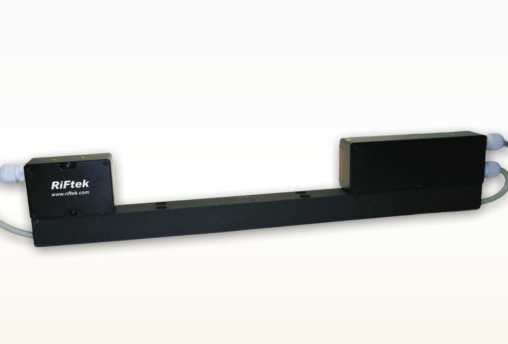
Laser Optical Micrometer, RF656 Series
|
|
|
- Juniper Craig
- 5 years ago
- Views:
Transcription


1
2 2 Contents 1. Safety precautions Electromagnetic compatibility General information Basic technical data Example of item designation when ordering Structure and operating principle Ways of using Dimensions and mounting Overall and mounting dimensions Connection Designation of connector contacts Cables Configuration parameters Sampling mode Sampling period Number of averaged values/time of averaging Type of the result The micrometer can provide the following types of results: Nominal value and tolerances Logical outputs operation modes Number of borders Numbers of borders under control Description of RS232 and RS485 interfaces RS232 port RS485 port Modes of data transfer Configuration parameters Rate of data transfer through serial port Net address Factory parameters table Interfacing protocol Serial data transmission format Communication sessions types Request Message Answer Data stream Request codes and list of parameters Analog outputs Current output 4 20 ma Voltage output Configuration parameters Range of the analog output Analog output operation mode Factory parameters table Request codes and list of parameters Request codes table List of parameters Notes Examples of parameters installation Examples of communication sessions Parameterization program Function Obtaining connection to micrometer... 18
3 14.3. Setting and saving parameters of the sensor Setting parameters Setting of deviation type result Saving parameters Saving and writing a group of parameters Operation of micrometer Warranty policy Distributors Annex 1. Sensors produced by RIFTEK
4 Environment resistance Laser Optical Micrometer, RF656 Series 1. Safety precautions Use supply voltage and interfaces indicated in the micrometer specifications. In connection/disconnection of cables, the micrometer power must be switched off. Do not use micrometers in locations close to powerful light sources. To obtain stable results, wait about 20 minutes after sensor activation to achieve uniform micrometer warmup Electromagnetic compatibility The micrometers have been developed for use in industry and meet the requirements of the following standards: EN 55022:2006 Information Technology Equipment. Radio disturbance characteristics. Limits and methods of measurement. EN :2005 Electromagnetic compatibility (EMC). Generic standards. Immunity for industrial environments. EN :2006 Electrical Equipment for Measurement, Control, and Laboratory Use. EMC Requirements. General requirements. 3. General information The optical micrometers are intended for noncontact measuring and checking of displacement, dimensions, surface profile, deformation, gaps of technological objects. The series includes 2 models with the measurement range, from 6 to 25 mm. 4. Basic technical data Model РФ Measurement range, mm 1х6 5х25 Distance between receiver and emitter, mm Linearity 1, um 0,5 1 Max. measurement frequency, Hz 800 Light source laser safety Class light diode 1 (IEC608251) Output digital RS232 (max. 460,8 kbit/s) or RS485 (max. 460,8 kbit/s) interface analog 4 20 ma ( 500 Ω load) or 0 10 V Synchronization input 2,4 5 В (CMOS, TTL) Logic output programmed functions, NPN: 100 ma max; 40 V max for output Power supply, V 24 (13 38) Power consumption, W 1,5..2 Enclosure rating IP67 (RF65625) Vibration 20g/ Hz, 6 hours, for each of XYZ axes Shock 30 g / 6 ms Operation temperature, С , Permissible ambient light, lx 7000 Relative humidity 3585% Housing material aluminum Weight (without cable), gram
5 1 Typical data obtained when a knife edge was used to interrupt the laser beam 5 5. Example of item designation when ordering RF656XSERIALANALOGINLOUTССM Symbol X SERIAL Description Base distance (6 or 25), mm The type of serial interface: RS or RS ANALOG Attribute showing the presence of 4 20 ma ( I ) or 0 10V ( U ) IN Trigger input (input of synchronization) presence LOUT Availability of programmed logical output* CC Cable gland CG, or cable connector CC М Cable length, m Example. RF IINСG operating range 25 mm, RS232 serial port, 4 20mA, trigger input, cable connector, 3 m cable length. *When ordering micrometer with logical outputs (LOUT), the micrometer goes only with cable gland (CG). 6. Structure and operating principle The micrometer operation is based on the socalled shadow principle, Fig.1. The micrometer consists of two blocks transmitter and receiver. Radiation of a semiconductor laser 1 is collimated by a lens 2. With an object placed in the collimated beam region, shadow image formed is scanned with a CCD photodetector array 3. A processor 4 calculates the position (size) of the object from the position of shadow border (borders). Transmitter Излучатель Object Объект Receiver Приемник 7. Ways of using Figure 1 Ways of using the micrometer for gauging of technological objects are shown in Fig. 2. Fig.2.1 measuring of the edge position; Fig.2.2. measuring of size or position; Fig.2.3. measuring of the gap value or position; Fig.2.4. measuring of internal or external dimension; Fig.2.5. measuring of the size or position of largesize objects.
6 ИЗЛУЧАТЕЛЬ Laser Optical Micrometer, RF656 Series 6 Figure Dimensions and mounting 8.1. Overall and mounting dimensions Overall and mounting dimensions of the micrometers are shown in Figures 3 and 4. Micrometer package is made of anodized aluminum. The rail have fastening holes allowing setup of the device on equipment. Measuring range ИЗМЕРИТЕЛЬНАЯ ОБЛАСТЬ 6 R E 2 ПРИЕМНИК RECEIVER Picture. 4. RF6566
7 RECEIVER TRANSMITTER 7 Measuring range GUIDING LINE Optical axle Picture. 4. RF Connection 9.1. Designation of connector contacts View from the side of connector contacts used in the micrometer is shown in the following figures. (Binder 702 Series, # )
8 8 Designation of contacts is given in the following tables: Model of the sensor Pin number Assignment 232U/IINAL 485U/IINAL IN Gnd (power supply) TXD RXD Gnd (Common for signals) AL U/I Power U+ IN Gnd (power supply) DATA+ DATA Gnd (Common for signals) AL U/I Power U+ When ordering micrometer with logical outputs (LOUT), the micrometer goes only with cable gland (CG) Cables Designation of cable wires is given in the table below: Cable #1 Model of the sensor Pin number Assignment Wire color 232U/IINAL DB9 DB9 DB Power U+ Gnd (power) TXD RXD U/I IN Gnd (Common for signals) Red Brown Green Yellow Blue White Gray 485U/IINAL 485U/IINLOUTCG DB9 DB9 DB9 DB9 DB9 DB Power U+ Gnd (power) TXD RXD U/I AGnd IN Gnd (Common for signals) NormLimit UpLimit LowLimit Power U+ Gnd (power) DATA+ DATA U/I AGnd IN Gnd (Common for signals) NormLimit UpLimit LowLimit Red Brown Green Yellow Blue Gray Violet Black White and Green Red and Blue Gray and Pink Red Brown Green Yellow Blue Gray Violet Black White and Green Red and Blue Gray and Pink
9 9 10. Configuration parameters The nature of operation of the micrometer depends on its configuration parameters (operation modes), which can be changed only by transmission of commands through serial port RS232 or RS485. The basic parameters are as follows: Sampling mode This parameter specifies one of the two result sampling options in the case where the micrometer works in the data stream mode: Time Sampling; Trigger Sampling. With Time Sampling selected, the micrometer automatically transmits the measurement result via serial interface in accordance with selected time interval (sampling period). With Trigger sampling is selected, the micrometer transmits the measurement result when external synchronization input (IN input of the sensor) is switched and taking the division factor set into account Sampling period If the Time Sampling mode is selected, the sampling period parameter determines the time interval in which the sensor will automatically transmit the measurement result. The time interval value is set in increments of 0.01 ms. For example, for the parameter value equal to 100, data are transmitted through bitserial interface with a period of 0,01*100 = 1 ms. If the Trigger Sampling mode is selected, the sampling period parameter determines the division factor for the external synchronization input. For example, for the parameter value equal to 100, data are transmitted through bitserial interface when each 100 th synchronizing pulse arrives at IN input of the micrometer. Note 1. It should be noted that the sampling mode and sampling period parameters control only the transmission of data. The micrometer operation algorithm is so built that measurements are taken at a maximum possible rate determined by the integration time period, the measurement results is sent to buffer and stored therein until a new result arrives. The abovementioned parameters determine the method of the readout of the result form the buffer. Note 2. If the bitserial interface is used to receive the result, the time required for data transmission at selected data transmission rate should be taken into account in the case where small sampling period intervals are used. If the transmission time exceeds the sampling period, it is this time that will determine the data transmission rate. Note 3. It should be taken into account that micrometers differ from other devices by some parameters dispersion of internal generator that influences on accuracy of time sampling period Number of averaged values/time of averaging This parameter specifies the number of source results to be averaged for deriving the output value or time of the averaging. The use of averaging makes it possible to reduce the output noise and increase the sensor resolution. Averaging over a number of results does not affect the data update in the sensor output buffer.
10 10 In case of time averaging, data in the output buffer are updated at a rate equal to the averaging period. Note. Maximum parameters value is Type of the result The micrometer can provide the following types of results: object size, or position, or deviation of size (position) from the target (nominal) value Nominal value and tolerances The nominal value (size or position) can be transmitted as a pameter or preset by teaching. In the course of measurement, the micrometer controls sizes going beyond the permissible limits. Value of tolerances can be transmitted as parameters Logical outputs operation modes Logical outputs of the micrometer are used to signal that the size under control is within or outside the tolerances selected. Logics of operation of the outputs can be changed, i.e. activate either low or high logical level Number of borders A border means lightshadow transition or shadowlight transition which forms a shadow image of the object. Measurement is only conducted in the case where the number of borders detected by micrometer corresponds to a given parameter Numbers of borders under control The measurement domain can include up to 8 borders, however, measurement can be made in relation to any two borders (hereinafter borders А and В), whose numbers are specified by this parameter. Border numbers are counted in the direction of scanning. Direction of scanning is indicated on the body of receiver The reserved parameters are used for the micrometers setting. Change of these parameters can lead to infringement of micrometer calibration. Correct change of parameters is made with the help of the installation program supplied with the micrometer. 11. Description of RS232 and RS485 interfaces RS232 port The RS232 port ensures a pointtopoint connection and allows the sensor to be connected directly to RS232 port of a computer or controller RS485 port In accordance with the protocol accepted and hardware capability, the RS485 port makes it possible to connect up to 127 sensors to one data collection unit by a common bus circuit.
11 Modes of data transfer Through these serial interfaces measurement data can be obtained by two methods: by single requests (inquiries); by automatic data streaming (stream) Configuration parameters Rate of data transfer through serial port This parameter defines the rate of data transmission via the bitserial interface in increments of 2400 bit/s. For example, the parameter value equal to 4 gives the transmission rate of 2400*4 = 9600 bit/s. Note. The maximum transmission rate for RS232 interface is 460,8 kbit/s, and for RS485 interface the rate is 921,6 kbit/s Net address. This parameter defines the network address of the sensor equipped with RS485 interface. Note. Network data communications protocol assumes the presence of master in the net, which can be a computer or other informationgathering device, and from 1 to 127 slaves (RF656 Series sensors) which support the protocol. Each slave is assigned a unique network identification code a device address. The address is used to form requests or inquiries all over the net. Each slave receive inquiries containing its unique address as well as 0 address which is broadcastoriented and can be used for formation of generic commands, for example, for simultaneous latching of values of all sensors and for working with only one sensor (with both RS232 port and RS485 port) Factory parameters table Parameter Value Baud rate 9600 bit/s Net address 1 Mode of data transfer request Interfacing protocol Serial data transmission format Data message has the following format: 1 startbit 8 data bits 1 odd bit 1 stopbit Communication sessions types The communications protocol is formed by communication sessions, which are only initiated by the master (PC, controller). There are two kinds of sessions with such structures: 1) request, [ message ] [ answer ], square brackets include optional elements 2) request data stream [ request ] Request Request (INC) is a twobyte message, which fully controls communication session. The request message is the only one of all messages in a session where most significant bit is set at 0, therefore, it serves to synchronize the beginning of the session.
12 12 In addition, it contains the device address (ADR), code of request (COD) and, optional, the message [MSG]. "Request" format: Byte 0 Byte 1 [ Bites 2 N ] INC0(7:0) INC1(7:0) MSG 0 ADR(6:0) COD(3:0) Message "Message is data burst that can be transmitted by master in the course of the session. All messages with a "message" burst contain 1 in the most significant digit. Data in a message are transferred in tetrads. When byte is transmitted, lower tetrad goes first, and then follows higher tetrad. When multibyte values are transferred, the transmission begins with lower byte. The following is the format of two message data bursts for transmission of byte: DAT(7:0) Byte 0 Byte DAT(3:0) DAT(7:4) Answer "Answer is data burst that can be transmitted by slave in the course of the session. All messages with a message burst contain 1 in the most significant digit. Data in a message are transferred in tetrads. When byte is transmitted, lower tetrad goes first, and then follows higher tetrad. When multibyte values are transferred, the transmission begins with lower byte. When answer is transmitted, the message contains: SBbit, characterizes the updating of the result. If SB is equal to "1" this means that the sensor has updated the measurement result in the buffer, if SB is equal to "0" then nonupdated result has been transmitted (see. Note 1, p.10.3.). SB=0 when parameters transmit; two additional bits of cyclic binary batch counter (CNT). Bit values in the batch counter are identical for all sendings of one batch. The value of batch counter is incremented by the sending of each burst and is used for formation (assembly) of batches or bursts as well as for control of batch losses in receiving data streams. The following is the format of two answer data bursts for transmission of byte: DAT(7:0) Byte 0 Byte 1 1 SB CNT(1:0) DAT(3:0) 1 SB CNT(1:0) DAT(7:4) Data stream Data stream is an infinite sequence of data bursts or batches transmitted from slave to master, which can be interrupted by a new request. In transmission of data stream one of the slaves fully holds data transfer channel, therefore, when master produces any new request sent to any address, data streaming process is stopped. Also, there is a special request to stop data streaming Request codes and list of parameters Request codes and list of parameters are presented in Chapter 13.
13 RF603 1 nf Voltmeter RF605 RF Om 5 nf Вольтметр Laser Optical Micrometer, RF656 Series 12. Analog outputs Changing of the signal at analog output occurs in synchronism with the changing of the result transferred through the bitserial interface Current output 4 20 ma 13 The connection scheme is shown in the figure. The value of load resistor should not be higher than 500 Ом. To reduce noise, it is recommended to install RC filter before the measuring instrument. The filter capacitor value is indicated for maximum sampling frequency of the sensor (9,4 khz) and this value increases in proportion to the frequency reduction. Синий Blue 10 kom Серый Gray Voltage output The connection scheme is shown in the figure. To reduce noise, it is recommended to install RC filter before the measuring instrument. The filter capacitor value is indicated for maximum sampling frequency of the sensor (9,4 khz) and this value increases in proportion to the frequency reduction. Blue 10 kom Gray Configuration parameters Range of the analog output While working with the analog output, resolution can be increased by using the Window in the operating range function which makes it possible to select a window of required size and position in the operating range of the sensor within which the whole range of analog output signal will be scaled. Note. If the beginning of the range of the analog signal is set at a higher value than the end value of the range, this will change the direction of rise of the analog signal Analog output operation mode When using window in the operating range function, this mode defines the analog output operation mode. Analog output can be: in the window mode or in the full mode.
14 14 "Window mode". The entire range of the analog output is scaled within the selected window. Outside the window, the analog output is "0". "Full mode". The entire range of the analog output is scaled within the selected window (operating range). Outside the selected window, the whole range of the analog output is automatically scaled onto the whole operating range of the sensor (sensitivity range) Factory parameters table Range of the analog output Analog output operation mode 13. Request codes and list of parameters Request codes table Measuring range of sensor Window Request code Description Message (size in bytes) Answer (size in bytes) 01h Device identification device type (1) firmware release (1) serial number (2) base distance (2) range (2) 02h Reading of parameter code of parameter (1) value of parameter (1) 03h Writing of parameter code of parameter (1) value of parameter (1) 04h Storing current parameters to constant AAh (1) constant AAh (1) FLASHmemory 04h Recovery of parameter default constant 69h (1) constant 69h (1) values in FLASHmemory 05h Latching of current result 06h Inquiring of result result (2) 07h Inquiring of a stream of results stream of results (2) 08h Stop data streaming 0Сh Teaching constant 0Ch (1) List of parameters Code of parameter Name Values 00h Sensor ON 1 laser is ON, measurements are taken (default state); 0 laser is OFF, sensor in power save mode 01h Analog output ON 1/0 analog output is ON/OFF; if a sensor has no analog output, this bit will remain in 0 despite all attempts of writing 1 into it. 02h Synchronization control byte x,x,x,x,x,c,x,s control byte which determines priority of sampling, bit S; and bit of mutual synchronization, C bites x do not use; bit S: 0 priority of time sampling (default) 1 priority of trigger sampling bit C: 0 mutual synchronization ON (on default); 1 mutual synchronization OFF; 03h Network address (default 1) 04h 05h Rate of data transfer through serial port Reserved 1 192, (default 4) specifies data transfer rate in increments of 2400 baud; e.g., 4 means the rate of =9600baud. (NOTE: max baud rate = )
15 15 06h Number of averaged values 1 128, (default 1) 07h Reserved 08h Lower byte of the sampling period 1) , (default 100) 09h Higher byte of the sampling period the time interval in increments of 0.01 ms with which sensor automatically communicates of results on streaming request (priority of sampling = 0); 2) , (default 100) divider ratio of trigger input with which sensor automatically communicates of result on streaming request (priority of sampling = 1) 0Ah Reserved 17h Lower zero point , (by default 0) 18h Higher byte zero point specifies magnitude of the nominal value in relation to which deviation is calculated 1Eh Type of results and number of borders 0XYh, (by default 00h) High tetrad X number of borders under control minus 1. For example, when diameter is measured two borders must be checked. Parameter X = 2 1=1; Low tetrad Y measurement mode: 0 measurement of position of one border (knife); 1 measurement of the distance between borders А and В (measurement of object size). Result = В А. (Numbers of borders А are В set by parameter 1Fh) 2 measurement of object position. Result = (В + А)/2; 3 measurement of position of border А; 1Fh Numbers of borders under control 0XYh (by default 00h) High tetrad X serial number of border А minus 1; Low tetrad Y serial number of border В minus 1; 22h 23h 24h 25h 26h Notes Low byte of the minimal tolerance (LowLimit) High byte of minimal tolerance (LowLimit) Low byte of the maximum tolerance (UpLimit) High byte of the maximum tolerance (UpLimit) Output signal logics control byte UpLimit, LowLimit , (by default 0) Specifies minimum permissible value of deviation value from the nominal value , (by default 0) Specifies maximum permissible value of deviation value from the nominal value x,x,x,x,x,n,u,l L bit signal logics control bit, LowLimit: 0 LowLimit low level active, 1 LowLimit high level active; U bit signal logics control bit, UpLimit: 0 UpLimit low level active, 1 UpLimit high level active; Nbit PASS signal logics control bit: 0 Normal low level active, 1 Normal high level active; All values are given in binary form. Base distance and range are given in millimeters. The value of the result transmitted by a sensor (D) is so normalized that 4000h (16384) corresponds to a full range of the sensor (S in mm), therefore, the result in millimeters is obtained by the following formula: X=D*S/4000h (mm) (1). On special request (05h), the current result can be latched in the output buffer where it will be stored unchanged up to the moment of arrival of request for data transfer. This request can be sent simultaneously to all sensors in the net in the broadcast mode in order to synchronize data pickup from all sensors. When working with the parameters, it should be borne in mind that when power is OFF the parameter values are stored in nonvolatile FLASHmemory of the sensor. When power is ON, the parameter values are read out to RAM
16 of the sensor. In order to retain these changes for the next powerup state, a special command for saving current parameter values in the FLASHmemory (04h) must be run. Parameters with the size of more than one byte should be saved starting from the highorder byte and finishing with the loworder byte. ATTENTION! It's forbidden to configure sensors switched on to the RS485! Examples of parameters installation 1 Measuring the position of a knife 1 border, А = 1, В = 1; Parameters 1Eh = 00h, 1Fh = 00h; 2 Measuring the diameter 2 borders, А = 1, В = 2; Parameters 1Eh = 11h, 1Fh = 01h; 3 Measuring the slit size 2 borders, А = 1, В = 2; Parameters 1Eh = 11h, 1Fh = 01h; 4 Measuring the rod center 2 borders, А = 1, В = 2; Parameters 1Eh = 12h, 1Fh = 01h; 5 Measuring the inner diameter of a ring 4 borders, А = 2, В = 3; Parameters 1Eh = 31h, 1Fh = 12h Examples of communication sessions 1) Request "Device identification". Condition: device address 1, request code 01h, device type 61, firmware release 88 (58h), serial number 0402 (0192h), base distance 80mm (0050h), measurement range 50мм (0032h), packet number 1. The request format: Byte 0 Byte 1 [ Bytes 2 N ] INC0(7:0) INC1(7:0) MSG 0 ADR(6:0) COD(3:0) Request from Master" Byte 0 Byte 1 INC0(7:0) INC1(7:0) h 81h The following is the format of two answer data bursts for transmission of byte DAT(7:0): DAT(7:0) Byte 0 Byte CNT(1:0) DAT(3:0) 1 0 CNT(1:0) DAT(7:4) Answer of Slave : Device type: DAT(7:0) Byte 0 Byte h 96h Firmware release DAT(7:0) Byte 0 Byte
17 17 98h Serial Number DAT(7:0) Byte 0 Byte h 92h 96h DAT(7:0) Byte 0 Byte h 90h Base distance DAT(7:0) Byte 0 Byte h 95h DAT(7:0) Byte 0 Byte h 90h Measurement range DAT(7:0) Byte 0 Byte h 93h DAT(7:0) Byte 0 Byte h 90h Note: as bust number =1, then CNT=1 2) Request "Reading of parameter". Condition: device address 1, request code 02h, code of parameter 05h, value of parameter 04h, packet number 2. Request ( Master ) 01h;82h; Message ( Master ) 85h, 80h; Answer ( Slave ) A4h, A0h 3) Request "Inquiring of result". Condition: device address 1, result 02A5h, packet number 3. Request ( Master ) 01h;86h; Answer ( Slave ) B5h, BAh, B2h, B0h Measured distance (mm) (for example, range of the sensor= 50 mm): X=677(02A5h)*50/16384 = mm 4) Request "writing sampling regime (trigger sampling)". Condition: device address 1, request code 03h, code of parameter 02h, value of parameter 01h. Request ("Master") 01h, 83h; Message ("Master") 82h, 80h, 81h, 80h; 5) Request: "writing the divider ration" Condition: divider ration 1234=3039h, device address 1, request code 03h, code of parameter 09h (first or higher byte), value of parameter 30h

18 Request ("Master") 01h, 83h Message ("Master") 89h, 80h, 80h, 83h and for lower byte, code of parameter 08h, value of parameter 39h Request ("Master") 01h, 83h Message ("Master") 88h, 80h, 89h, 83h Parameterization program Function The RF65ХSP software (( is intended for: 1) Testing and demonstration of work of RF65x series sensors; 2) Setting of the sensor parameters; 3) Reception and gathering of the sensor data signals Obtaining connection to micrometer Once the program is started, the popup window emerges: To obtain connection it is necessary: select СОМport whereto the sensor is connected (logical port if the sensor is connected via USBadapter) select transmission rate (Baud rate) at which the sensor will work select the sensor network address, if necessary press the Connect button. If the selected parameters correspond to the parameters of the micrometer interface, the program will identify the micrometer, read and display its configuration parameters:


19 Setting and saving parameters of the sensor Setting parameters The opening part of the "RF65XSP" application ("Parameter Value Table ") allows one to edit and enter the required parameters into both RAM and FLASH memory of the micrometer. to switch ON/OFF the micrometer, click the left mouse key twice in the Value field of the Sensor On/Off parameter; to set Synchronization Control Byte, press the key in the Value field, thus calling out "Synchronization Control Byte" edit menu; to set the exchange speed, click the left mouse key in the Value field of the UART Baud rate line, thus calling out the list of permissible speeds; in the Averaged values counter line, select the number of measurements to be averaged directly in the micrometer. Factory setting is "0"; in the lines Analog output range (BEG) and (END), it is possible to set the analog output window boundaries in increments of 0.1% of the working range. It is also possible to call out the control toolbar by clicking twice in the Value field: Pressing the left mouse key activates red cursor which indicates the beginning of the scaling range, while pressing the right mouse key activates blue cursor indicating the end of the scaling range. To set up working window boundaries, press the respective button and, holding it in the pressed position, move the cursor within the
20 sensor measurement region. Then, boundaries of the selected window will be displayed in the lower line in % (percentage) of the range Setting of deviation type result 20 in the line "Number of Borders", select the number of borders; in the line "Measure type", select the type of result; in the fields "Border A" and "Border B", specify numbers of borders under control; For deviation type result, the window boundaries must be defined so that the value corresponding to zero deviation is located in the middle of the window. In this case, the middle part of the analog output range (12mA or 5V) will correspond to zero deviation. the field "Etalon" is used to specify nominal value. Two choices are possible: place a standard (reference) object within the measurement zone and press "Teach" button. In the field "Etalon" the reference measurement value will appear. type the value of the size (position) of the standard object in the field. in the fields "LowLimit" and "UpLimit" write tolerances; in the field "OutLogic"tune output logic Saving parameters after setting one or several parameters as required, it is necessary to write them into the sensor memory, this is done by executing File>Write parameters. Note: a special key is offered for fast writing of parameters of the RS232/RS485 interfaces; perform testing of the sensor operation with new parameters; to store new parameters in nonvolatile memory, execute File>Write to flash. Now, with any subsequent activation of the sensor it will work in the configuration you have selected.
 or Load All (to store all parameters). Perform testing of the micrometer operation with new parameters.")
21 Saving and writing a group of parameters After setting one or more required parameters by clicking the right key of the mouse on the left panel "Parameters save" menu is activated. Select Load (to store one parameter) or Load All (to store all parameters). Perform testing of the micrometer operation with new parameters. To store the new parameters in the micrometer memory, click the "Write to FLASH" of "Parameters save" menu. The micrometer will operate with these parameter settings in subsequent switched on. 15. Operation of micrometer 1. Place an object within the micrometer operating range. 2. Clicking the "Measure" button leads to indication of the result of a continuous measurement of the object position (dimension) on the display. 3. Pressing "Teach" button the measurement results are entered in Etalon parameter, then the micrometer move to the measurement deviation of the etalon mode. Micrometer works in a measurement deviation mode when parameter 'Etalon' has any nonzero value. 5. Data coming from the micrometer are accumulated and stored in a circular buffer with measurements storage capacity. The "Oscilloscope" window shows graphic representation of the accumulated data. (Xaxis number of the result, Yaxis coordinates). By clicking left key of the mouse scale of the image can be changed, the right key is used to drag the graphic image within viewing region. By clicking the right key "Save to the file" menu is activated. 16. Warranty policy Warranty assurance for the Laser triangulation sensors RF months from the date of putting in operation; warranty shelflife 12 months
22 17. Distributors BENELUX CHINA CZECH REPUBLIC 22 ALTHERIS bv Scheveningseweg KS The Hague The Netherlands Tel: 0031(0) Fax: 0031(0) INDONESIA Zhenshangyou Technologies Co.,Ltd. Rm , Zhongyou Hotel 1110 Nanshan Road, Nanshan District Shenzhen, China Tel: 86) /8011/8012 Fax: (86) / ITALY RMT Ltd. Zahradni Paskov Tel: Fax: GERMANY PT. Dhaya Baswara Saniyasa Sentra Niaga Puri Indah Blok T6. 41 Kembangan, Jakarta Tel: Fax: LITHUANIA FAE s.r.l. Via Tertulliano, Milano Tel: Fax: MALAYSIA Disynet GmbH Westwall 12 D41379 Brueggen Tel: +49(2157)87990 Fax: +49(2157) POLAND JSC "Comexim" Serbentu. 222, LT 5419 Siauliai Tel./Fax: PORTUGAL OptoCom Equiptech (M) Sdn H492, Jalan 5, Cosmoplex Industrial Park. Bandar Baru Salak Tinggi, Sepang Tel: / RUSSIA P.U.T. GRAW Sp. z o.o. ul. Karola Miarki 12, skr Gliwice, Poland tel./fax: +48 (32) info@graw.com RUSSIA UltraSens. Tel.: (0351) Fax: (0351) geral@ultrasens.com SOUTH KOREA SensorikaM LLC Dmitrovskoye shosse 64, к , Moscow, Russia Tel.: Fax: info@sensorika.com SPAIN IntellectOptic Ekaterinburg Mira str tel/fax tel/fax pesterev@dtest.ru SWEDEN Santec Co 322, Wongokdong Danwongu Ansansi Kyunggido, Tel : Fax: santec@naver.com SWITZERLAND Iberfluid Instruments C/ Cardenal Reig, BARCELONA Tel Fax myct@iberfluid.com UKRAINE BLConsult Rävbergsvägen 31, SE NORA Contactperson: Berndt Lundström Directnumber: +46 (0) Tel.: +46 (0) info@blconsult.se United Kingdom, Ireland ID&T Gmbh Gewerbestrasse 12/a 8132 Egg (Zurich) Tel.: +41 (0) Fax: +41 (0) info@idtlaser.com KODA Frunze st 22, 61002, Harkov, Ukraine Tel/fax.: mail@koda.com.ua Ixthus Instrumentation The Stables, Williams' Barns Tiffield road, Towcester, Northents, UK Tel.: Fax: info@ixthus.co.uk


 2D/3D Measurements; 5 mm to 1500 mm ranges; 0,05% of F.S. linearity; 1000 profiles/s sampling rate; scanners on the base of BLUE and IR lasers; Optical micrometers.")

23 18. Annex 1. Sensors produced by RIFTEK Laser triangulation sensors. RF60x Series 23 dimensions and displacements measurement; 2 mm to 2,5 m ranges; ±1 um accuracy; 180 khz sampling frequency; sensors on the base of BLUE and IR lasers; High Speed sensors (HS); The series includes four lines of models: RF603 universal sensors with 2 to 1250 mm operating ranges; RF603HS high speed sensors; RF600 largebase and long range sensors; RF605 compact value sensors. Laser 2D scanners. RF620HS (DHS) 2D/3D Measurements; 5 mm to 1500 mm ranges; 0,05% of F.S. linearity; 1000 profiles/s sampling rate; scanners on the base of BLUE and IR lasers; Optical micrometers. RF65x Series diameter, gaps and displacements measurement; 6 mm to 60 mm ranges; ±0.5 um accuracy; 1000 Hz sampling rate; The series includes two lines of models: RF651 direct through beam micrometers with 25 and 59 mm ranges, and accuracy ±5 µm; RF656 high precision through beam micrometers with telecentric lens, 5 and 25 mm. ranges and accuracy ±0,5 µm;

24 Absolute linear encoders. RF25x Series dimensions and displacements measurement; innovative technology of absolute measurement; 3 to 55 mm ranges; 0,1 um resolution; 24 The series include two models: RF251 sensors for hard industrial environments; RF256 sensors with a builtin display option for laboratory environments. All details about measurement sensors and instruments are on our website
OPTICAL MICROMETER. RF651 Series. User's manual
 OPTICAL MICROMETER RF65 Series User's manual 22, Logoisky tract, Minsk 220090, Republic of Belarus tel/fax: +375 7 28 36 57 info@riftek.com www.riftek.com Certified according to ISO 900:2008 Contents.
LENORD. +BAUER... automates motion. Magnetic absolute rotary encoder GEL 2037 with heavy duty flange or tooth wheel adapter
 Magnetic absolute rotary encoder GEL 2037 with heavy duty flange or tooth wheel adapter LENORD +BAUER... automates motion. Technical information Version 01.12 General Multiturn absolute rotary encoders
SIMPLY PRECISE PRELIMINARY. Preliminary product overview - LAK encoder. LAK 1 Absolute linear encoder with signal control
 PRELIMINARY Preliminary product overview - LAK encoder LAK 1 Absolute linear encoder with signal control 2 Index 1. Overview 3 2. Applications 3 3. Technical data 4 4. General specifications 5 5. Dimensions
CCD-array with RTSC. Laserdiode. Multi-lens optics. Filter
 Laser-Wegsensoren optoncdt Options (Triangulation) 2 Table of Contents optoncdt 7-2 / 72-2 / 7-3... 3 optoncdt 7-(6)... optoncdt 7-2... 5 optoncdt 7-2/9... 6 optoncdt 7-2()... 7 optoncdt 22-2(235)... 8
POSICHRON position sensor in a stainless steel pressure case. Voltage: V, 3 wire Current: ma, 3 wire
 Rod Profile with Analog Specifications POSICHRON position sensor in a stainless steel pressure case Protection class IP68 Compression-proof up to 15 bar Measurement range 0... 100 to 0... 5750 mm Absolute
IP 251 Universal Signal Converter SSI parallel RS232 parallel SSI RS232
 control motion interface ELEKTRO-TRADING sp. z o.o Tel. +48 (0-32) 734-55-72 Tel/Fax +48 (0-32) 734-55-70 E-Mail et@elektro-trading.com.pl http://www.elektro-trading.com.pl IP 251 Universal Signal Converter
Assembly Instructions
 Assembly Instructions optocontrol 2520 Functions Edge measurement with the shadow principle (Edge low-high; edge high-low) Measurement of diameter-, width-, gap incl. center axis Counting of edges or segments,
Torque Sensor Series 3000 and Series 4000
 Properties Sensorshaft with integrated torque and angle measurement Non-contact measurement system, high robustness Plug & Play solution, no additional electronics required Performance Measurement range
EVDP610 IXDP610 Digital PWM Controller IC Evaluation Board
 IXDP610 Digital PWM Controller IC Evaluation Board General Description The IXDP610 Digital Pulse Width Modulator (DPWM) is a programmable CMOS LSI device, which accepts digital pulse width data from a
ABSOLUTE ROTARY ENCODER SSI PROGRAMMABLE
 Main Features - Compact and heavy-duty industrial model - Interface: Synchronous-serial (RS422/485) - Housing: 58 mm - Shaft: 6 or 10 mm - Resolution: Max. 25 Bit =,554,42 steps over 4,096 revolutions
Modbus communication module for TCX2: AEX-MOD
 Modbus communication module for TCX2: Communication Specification TCX2 is factory installed in TCX2 series controllers with -MOD suffix, and is also available separately upon request for customer installation
MEASUREMENT APPLICATION GUIDE OUTER/INNER
 MEASUREMENT APPLICATION GUIDE OUTER/INNER DIAMETER Measurement I N D E X y Selection Guide P.2 y Measurement Principle P.3 y P.4 y X and Y Axes Synchronous Outer Diameter Measurement P.5 y of a Large Diameter
GPS Time and Frequency Reference Receiver
 $ GPS Time and Frequency Reference Receiver Symmetricom s 58540A GPS time and frequency reference receiver features: Eight-channel, parallel tracking GPS engine C/A Code, L1 Carrier GPS T-RAIM satellite
Technical data. General specifications. Linearity error ± 0.1 Functional safety related parameters MTTF d 700 a at 40 C Mission Time (T M ) L 10
 L 10") Model Number SYNCHRON SERIELLES INTERFACE Features Solid shaft SSI interface Up to Bit multiturn Free of wear magnetic sampling High resolution and accuracy Additionally push buttons for preset function
Model Number SYNCHRON SERIELLES INTERFACE Features Solid shaft SSI interface Up to Bit multiturn Free of wear magnetic sampling High resolution and accuracy Additionally push buttons for preset function
LASER. Analog Laser Displacement Transducer. LAM Series. Key-Features: Content:
 LASER Analog Laser Displacement Transducer LAM Series Key-Features: Content: Overview, Measuring Principle...2 Installation Instructions...3 Technical Data...4 Technical Drawings.7 Electrical Connection...9
Agilent AEDA-3300 Series Ultra Miniature, High Resolution Incremental Kit Encoders Data Sheet
 Description The AEDA-3300 series are high performance, cost effective, three-channel optical incremental encoder modules with integrated bearing stage. By using transmissive encoder technology to sense
Absolute multi-turn hollow shaft encoder BOMH Dignalizer SSI
 features high resolution multi-turn encoder up to - 8 bit single-turn - 8 bit multi-turn interface programmable permanent self-test reference point programmable general data voltage supply 5 VDC (05C)
POSICHRON position sensor in stick design. Protection class. Voltage: V, 3 wire Current: ma, 3 wire
 POSICHRON Position Sensor Stick Design with Analog Specifications POSICHRON position sensor in stick design Protection class IP67 Measurement range 0... 100 up to 0... 5750 mm Absolute position measurement
Distance Sensors BOD 26K.... with optional Master-Slave-Mode
 Distance... with optional Master-Slave-Mode Laser Distance The Balluff distance sensor not only detects the presence of objects, but can also indicate their precise position or location. This means the
High power radio transmission module MR03 type
 High power radio transmission module MR03 type User s manual CONTENTS 1. APPLICATION...3 2. MR03 MODULE SET...4 3. INSTALLATION...4 3.1 Module assembly...4 3.2 Connection diagrams...5 3.3 Connection way
Technical data. General specifications V DC No-load supply current I 0. typ. 50 ma Power consumption P 0
 Model Number SYNCHRON SERIELLES INTERFACE Cable pull rotary encoder with SSI interface Features Solid yet lightweight plastic construction Compact, slim design (the shaft of the mounted rotary encoder
This data sheet is only valid in association with the IL SYS INST UM E user manual.
 Inline counter terminal, version for extreme conditions, 1 counter input, 1 control input, 1 output, 24 V DC, 500 ma Data sheet 106148_en_03 PHOENIX CONTACT 2015-11-04 1 Description The terminal is designed
Technical data. General specifications. Linearity error ± 0.1 Electrical specifications Operating voltage U B
 Model Number SYNCHRON SERIELLES INTERFACE Features Very small housing Up to 32 Bit multiturn SSI interface Free of wear magnetic sampling High resolution and accuracy Description The ENA36IL series are
Technical data. General specifications. Linearity error ± 0.1 Functional safety related parameters MTTF d 700 a at 40 C Mission Time (T M ) L 10
 L 10") Model Number SYNCHRON SERIELLES INTERFACE Features Recessed hollow shaft SSI interface Up to Bit multiturn Free of wear magnetic sampling High resolution and accuracy Additionally push buttons for preset
Model Number SYNCHRON SERIELLES INTERFACE Features Recessed hollow shaft SSI interface Up to Bit multiturn Free of wear magnetic sampling High resolution and accuracy Additionally push buttons for preset
Controller for the Implementation of a Central or Decentralized Electrohydraulic System
 EFX 1624m Electronic Controller Programmed with Eaton CONTROL F(x) Software to IEC 61131-3 Standard 2nd CAN interface for gateway function according to SAE J1939 Supply voltage 10...32V DC Technical Data
Distance sensors. System description. Distance measurement using triangulation
 Distance sensors System description Distance measurement using triangulation The measurement principle of optical triangulation is suitable for the precise determination of distances at close range. With
Temposonics. E-Series Model ER. Magnetostrictive, Absolute, Non-contact Linear-Position Sensors. Analog and Start/Stop Outputs.
 Temposonics Magnetostrictive, Absolute, Non-contact Linear-Position Sensors Analog and Start/Stop Outputs SENSORS Document Part Number: 550996 Revision E Data Sheet FEATURES Linear, Absolute Measurement
Z500. High-Precision Sensor that Measures and Displays an Object's Profile. Profile Measuring System
 Profile Measuring System High-Precision Sensor that Measures and Displays an Object's Profile. Features OMRON's original line beam method provides a complete solution to profile measurement problems. Conventional
Ranges >500 mm: L10 = ±0.10 % f.s. L02 = ±0.02 % f.s. Ranges 500 mm: L10 = ±0.5 mm L02MM = ±0.2 mm Repeatability ±3 µm
 Flat Profile Housing with Analog POSICHRON position sensor Only 12 mm height and 36 mm width Protection class IP64 Measurement range 0... 100 to 0... 5750 mm Absolute position measurement Ultra flat profile
Voltage regulator TAPCON 240
 Voltage regulator TAPCON 240 Supplement 2398402/00 Protocol description for IEC 60870-5-103 All rights reserved by Maschinenfabrik Reinhausen Copying and distribution of this document and utilization and
Ultrasonic Multiplexer OPMUX v12.0
 Przedsiębiorstwo Badawczo-Produkcyjne OPTEL Sp. z o.o. ul. Morelowskiego 30 PL-52-429 Wrocław tel.: +48 (071) 329 68 54 fax.: +48 (071) 329 68 52 e-mail: optel@optel.pl www.optel.eu Ultrasonic Multiplexer
Technical data. General specifications V DC Power consumption P 0. 1 W Time delay before availability t v
 Model Number SYNCHRON SERIELLES INTERFACE Features Very small housing Up to 32 Bit multiturn SSI interface Free of wear magnetic sampling High resolution and accuracy Description The ENA36IL series are
FA Wireless SS Terminals
 FA Wireless SS Terminals WT30 Construct a Wireless System for ON/OFF Data Collection That Is Ideal for Monitoring Production Site Equipment Wireless Slave Station equipped with I/O. Height of 90 mm and
SPECTRO Series SPECTRO-3-FIO-UV-SL. Design. SPECTRO-3 Series True Color Sensors. Product name: Accessories: (p. 8-11)
") SPECTRO Series SPECTRO-3-FIO-UV-SL - Big working range: typ. 1 mm... 500 mm (depends on the fiber optics used and attachment optics) - Various UV fiber optics (reflected light operation) and attachment
SPECTRO Series SPECTRO-3-FIO-UV-SL - Big working range: typ. 1 mm... 500 mm (depends on the fiber optics used and attachment optics) - Various UV fiber optics (reflected light operation) and attachment
ICAM. Electronics & Software. Industrial Charge Amplifier for Applications in Manufacturing. Type 5073A...
 Electronics & Software ICAM Type 5073A... Industrial Charge Amplifier for Applications in Manufacturing The ICAM charge amplifier (Industrial Charge Amplifier Manufacturing) converts the piezoelectric
ABSOLUTE ROTARY ENCODER SSI
 Main Features - Compact and heavy-duty industrial model - Interface: Synchronous-serial (RS 422) - Housing: 58 mm - Shaft: 6 or 10 mm - Hollow shaft 12 mm - Blind hollow shaft 15 mm - Max. 65,56 steps
Select datum Page backward in. parameter list
 HEIDENHAIN Working with the measured value display unit ND Actual value and input display (7-segment LED, 9 decades and sign) Select datum Page backward in parameter list Confirm entry value Set display
Voltage regulator TAPCON 260
 Voltage regulator TAPCON 260 Supplement 2531975/00 Protocol description for IEC 60870-5-103 All rights reserved by Maschinenfabrik Reinhausen Copying and distribution of this document and utilization and
POSIWIRE. WS85 with internal magnetic encoder Position Sensor. Cable Extension Position Sensors. Datasheet
 Cable Extension Position Sensors with internal magnetic encoder Position Sensor Datasheet Copyright ASM GmbH Am Bleichbach 18-24 85452 Moosinning Germany The information presented in this data sheet does
745 Transformer Protection System Communications Guide
 Digital Energy Multilin 745 Transformer Protection System Communications Guide 745 revision: 5.20 GE publication code: GEK-106636E GE Multilin part number: 1601-0162-A6 Copyright 2010 GE Multilin GE Multilin
LENORD. +BAUER... automates motion. GEL 2037 with heavy duty flange or tooth wheel adapter. Technical information Version General.
 GEL 2037 with heavy duty flange or tooth wheel adapter LENORD +BAUER... automates motion. Technical information Version 2014-07 General Multiturn absolute rotary encoders with a resolution of up to 25
ABSOLUTE ROTARY ENCODER DEVICE NET
 Main Features - Compact and heavy-duty industrial model - Interface: CAN according to Device Net - Housing: 8 mm - Shaft: 6 or 0 mm - Resolution: Max. 2 Bit =,,2 steps over,096 revolutions - Code: Binary
ABSOLUTE ROTARY ENCODER SSI
 Main Features - Compact and heavy-duty industrial model - Interface: Synchronous-serial (RS422/485) - Housing: 58 mm - Shaft: 6 or 10 mm - Resolution: Max. 25 Bit =,554,42 steps over 4,096 revolutions
Encoder - Absolut 2RMHF-SSI
 Absolute Encoder: Ø24 mm Hollow Shaft: Ø3 mm to ¼ Inch Singleturn or Multiturn SSI Interface Binary or Gray Code Preset of Zero Position Choice of Counting Direction IP-Rating: IP64 or IP67 Mechanical
U8 I1. Linearity ±0.10 % f. s. (standard); optional ±0.05 % WB61
; optional ±0.05 % WB61") Analog Output Position sensor with measuring tape Measurement range up to 4000 mm class IP67/IP69K Stainless steel measuring tape Analog output Specifications Outputs Resolution U2 U8 I1 Voltage 0.5...
Analog Output Position sensor with measuring tape Measurement range up to 4000 mm class IP67/IP69K Stainless steel measuring tape Analog output Specifications Outputs Resolution U2 U8 I1 Voltage 0.5...
maxon document number:
 maxon document number: 791272-04 1 Table of contents... 2 2 Table of figures... 3 3 Introduction... 4 4 How to use this guide... 4 5 Safety Instructions... 5 6 Performance Data... 6 6.1 Motor data... 6
Confirm entry value Set display to value from Actual value and input display Select datum P79 (P80!) (7-segment LED,
 (7-segment LED,") HEIDENHAIN Working with the measured value display unit ND 261 Confirm entry value Set display to value from Actual value and input display Select datum P79 (P80!) (7-segment LED, Page backward in 9 decades
HEIDENHAIN Working with the measured value display unit ND 261 Confirm entry value Set display to value from Actual value and input display Select datum P79 (P80!) (7-segment LED, Page backward in 9 decades
Manual IF2008A IF2008E
 Manual IF2008A IF2008E PCI Basis Board Expansion Board Table of Content 1 Technical Data... 4 1.1 IF2008A Basic Printed Circuit Board... 4 1.2 IF2008E Expansion Board... 5 2 Hardware... 6 2.1 View IF2008A...
More Precision. wiresensor // Draw-wire displacement sensors
 More Precision wiresensor // Draw-wire displacement sensors 38 Industrial draw-wire sensors wiresensor P5 analog - Robust aluminum profile housing - Customized versions for OEM - Potentiometer, current
ST600 TRANSMITTER OPERATING INSTRUCTIONS
 ST600 TRANSMITTER OPERATING INSTRUCTIONS 1892 1273 These operating instructions are intended to provide the user with sufficient information to install and operate the unit correctly. The Wood and Douglas
RF1276 Long Distance Transceiver module V2.0
 1. General RF1276 series is a low cost, ultra-low power, high performance transparent two way semi-duplex LoRa modulation transceiver with operation at 169/433/868/915 Mhz. It integrates with high speed
Absolute encoder GEL 15X F. Serial (SSI) or parallel interface, PC-programmable. Technical information version 01.06
 or parallel interface, PC-programmable. Technical information version 01.06") Absolute encoder 5xF Serial (SSI) or parallel interface, PC-programmable Technical information version 0.06 converter module KM 50.0 - + 24 V DC + 0% 5X F connecting cable VK 50.2 (SSI) VK 50.3 (parallel)
Absolute encoder 5xF Serial (SSI) or parallel interface, PC-programmable Technical information version 0.06 converter module KM 50.0 - + 24 V DC + 0% 5X F connecting cable VK 50.2 (SSI) VK 50.3 (parallel)
U8 I1. Linearity ±0.10 % f. s.; optional ±0.05 % WB12
 Analog Output Position sensor with measuring tape Measurement range up to 4000 mm class IP67/IP69K Stainless steel measuring tape Analog output Specifications Outputs Resolution U2 U8 I1 Voltage 0.5...
Technical Explanation for Displacement Sensors and Measurement Sensors
 Technical Explanation for Sensors and Measurement Sensors CSM_e_LineWidth_TG_E_2_1 Introduction What Is a Sensor? A Sensor is a device that measures the distance between the sensor and an object by detecting
NOVOHALL Rotary Sensor non-contacting. Series RSC2800 digital SSI, SPI, Incremental
 NOVOHALL Rotary Sensor non-contacting Series RSC2800 digital SSI, SPI, Incremental The RSC 2800 sensor utilizes a contactless magnetic measurement technology to determine the measured angle. Unlike conventional
SL300 Snow Depth Sensor USL300 SNOW DEPTH SENSOR. Revision User Manual
 USL300 SNOW DEPTH SENSOR Revision 1.1.2 User Manual 1 Table of Contents 1. Introduction... 3 2. Operation... 3 2.1. Electrostatic Transducer... 4 2.2. SL300 Analog Board... 4 2.3. SL300 Digital Circuit
AccuStar Electronic Clinometer
 +/-60 o total sensing range CE certified Analog, digital and PWM outputs High accuracy / low cost Lightweight and compact Rugged plastic housing DESCRIPTION The AccuStar Electronic Clinometer is an extremely
SPECTRO Series SPECTRO-3-UV-SL. Design. SPECTRO-3 Series True Color Sensors. Product name:
 SPECTRO Series - Object distance typ. 1 mm... 50 mm - Integrated transmitter and receiver optics - Up to 3 colors (max. 64 colors in GROUP mode) can be taught - RS232 interface (USB or Ethernet adapter
ABSOLUTE ROTARY ENCODER SSI
 Main Features - Compact and heavy-duty industrial model - Interface: Synchronous -serial (RS 422) - Housing: 58 mm - Shaft: 6 or 10 mm - Hollow shaft 12 mm - Blind hollow shaft 15 mm - Max. 65,56 steps
Name Number of I/O points (words used) Model Antenna style. 512 outputs max. (32 words) Magnetic Base Antenna (1) --- WD30-AT001 (See note.
 Model Antenna style. 512 outputs max. (32 words) Magnetic Base Antenna (1) --- WD30-AT001 (See note.") DeviceNet Wireless Communication WD30 The DeviceNet wireless units, consisting of a DeviceNet wireless master station and a DeviceNet wireless slave station, allow wireless communication with DeviceNet
DeviceNet Wireless Communication WD30 The DeviceNet wireless units, consisting of a DeviceNet wireless master station and a DeviceNet wireless slave station, allow wireless communication with DeviceNet
Absolute encoders - SSI
 with through hollow shaft Features Encoder multiturn / SSI Optical sensing method Resolution: singleturn 14 bit, multiturn 12 bit Compact design Cost-efficient mounting High reliability by self-diagnostics
Select datum Page backward in parameter list
 HEIDENHAIN Working with the measured value display unit ND Actual value and input display (7-segment LED, 9 decades and sign) Select datum Page backward in parameter list Confirm entry value Set display
High Performance Process & Temperature Controllers
 C22 C62 C82 C83 High Performance Process & Temperature Controllers C72 C42 R22 01. Multi Color LCD Display 02. High Accuracy 18 Bit A-D Input and 15 Bit D-A Output 03. 200 msec Sampling Rate 04. True Universal
INPROX sensors. displacement MLS compact ccd-laser distance sensor
 compact ccd- distance sensor MLS7-250 high vibration and shock resistant -CCD specifications measuring range 250mm resolution >50µm measuring frequency 1000Hz small dimensions (mm) (65x50x20) high shock
POSICHRON position sensor in a stainless steel pressure tube. Protection class IP68/IP69K
 Round Profile Housing with Analog POSICHRON position sensor in a stainless steel pressure tube Protection class IP68/IP69K Underwater applications, permanent pressure-proof up to 15 bar Measurement range
Series 7000 Torque Sensor for PTO-shafts
 Properties PTO (Power Take-Off) shaft with integrated torque and angle measurement Non-contact measurement system, high robustness Special for PTO shafts 1 ¾ und 1 3/8 Plug & Play solution, no additional
Keysight Technologies How to Take Fast, Simultaneous Measurements of Two or More Signals Using BenchVue Software. Application Note
 Keysight Technologies How to Take Fast, Simultaneous Measurements of Two or More Signals Using BenchVue Software Application Note 02 Keysight How to Take Fast, Simultaneous Measurements of Two or More
Online data sheet. CLV601-0D200 CLV60x BAR CODE SCANNERS
 Online data sheet CLV601-0D200 CLV60x A B C D E F H I J K L M N O P Q R S T Detailed technical data Features Connection type Reading field Scanner design Focus Sensor Sensor resolution Light source Ordering
RF7129 Ultra-low power Tranceiver module V2.0
 1. General RF7129 series is a low cost, ultra-low power, high performance transparent two way semi-duplex GFSK transceiver with operation at 433/470/868/915 Mhz. It integrates with high speed MCU from
Laser Contour Log Profiling System
 Sitronic Laser Contour Log Profiling System LKM-400 LKM-700 LKM-900 LKM-1100 LKM-1400 2 Laser Log Profiling System (Log Measuring System) The Laser Profiling System LKM is a complete measuring system that
HAC-HM Series Data Radios
 HAC-HM Series Data Radios - 1 - Catalogue I. Features of HAC-HM Series...3 II. Application of HAC-HM Series...4 III. How to use HAC-HM Series...4 IV. Networking Application of HAC-HM Series... 11 Technical
Machine Vision Lyte-MV 2
 Machine Vision Lyte-MV 2 The Lyte-MV 2 Range The Lyte-MV 2 provides a reliable industrial light source for a wide range of machine vision applications including triangulation, 3D inspection and alignment.
Interface Description
 Interface Description True-Color-Sensor with IO-Link Ordering code: Part number: BFS000M BFS 33M-GSI-F01-S75 Document number: 920685 E 0726 03.123343 Edition K16 replaces Edition F16 Subject to changes
Line beam for fast, accurate measuring of height and width
 454 displacement sensor series Line beam for fast, accurate measuring of height and width Linearity of ±0.1% F.S. Sampling period of 0.5 ms (max. speed) 2-dimensional measurements at a significantly low
AR-DN-RS232. An-10 / Rapid RS232 Interface. Product Guide. Overview. Features
 AR-DN-RS232 An-10 / Rapid RS232 Interface Product Guide Overview The AR-DN-RS232 is a device that is used as a 2 way gateway between third party systems and the CP An-10 or Rapid lighting control systems
R&S ENV216 Two-Line V-Network For disturbance voltage measurements on single-phase EUTs
 R&S ENV216 Two-Line V-Network For disturbance voltage measurements on single-phase EUTs Test & Measurement Data Sheet 03.00 R&S ENV216 Two-Line V-Network At a glance The R&S ENV216 two-line V-network meets
Technical data. Your advantages
 Technical data Nominal torque: 50 Nm to 2.000 Nm, bidirectional Rotational speed: 10.000 rpm Accuracy: ±0,2 % Temperature range: -40 C to +85 C Protection class: IP50, IP65 Output signals: 0-10 V/4-20
ies-2309 Integrated Easy Servo
 Datasheet of the integrated easy servo motor ies-09 ies-09 Integrated Easy Servo Motor + Drive + Encoder, 0-0VDC, NEMA, 0.9Nm Features Easy servo control technology to combine advantages of open-loop stepper
Protection class. Male 8 pin socket M12 (ADCANOP: 5 pin socket)
") WS10SG Analog, SSI or CANopen Output Very compact sensor for industrial applications Protection class IP65 Measurement range 0... 100 mm to 0... 1250 mm Analog output or A/D converted synchronous serial
WS10SG Analog, SSI or CANopen Output Very compact sensor for industrial applications Protection class IP65 Measurement range 0... 100 mm to 0... 1250 mm Analog output or A/D converted synchronous serial
MU110-16R(K) Digital output module 16 channel. User guide
 Digital output module 16 channel. User guide") MU110-16R(K) Digital output module 16 channel User guide MU110-16R(K)_2016.12_0220_EN All rights reserved Subject to technical changes and misprints akytec GmbH Vahrenwalder Str. 269 A 30179 Hannover Germany
MU110-16R(K) Digital output module 16 channel User guide MU110-16R(K)_2016.12_0220_EN All rights reserved Subject to technical changes and misprints akytec GmbH Vahrenwalder Str. 269 A 30179 Hannover Germany
POSIWIRE. WS12 Position Sensor. Cable Extension Position Sensors. Datasheet
 Cable Extension Position Sensors Position Sensor Datasheet Copyright ASM GmbH Am Bleichbach 18-24 85452 Moosinning Germany The information presented in this data sheet does not form part of any quotation
Interface Description
 Interface Description True-Color-Sensor with IO-Link Ordering code: Part number: BFS000M BFS 33M-GSI-F01-S75 Document number: 920685 E 01.119905 Edition E15 replaces Edition C15 Subject to changes Page
Fuzzy Temperature Controllers E5AF
 Fuzzy Temperature Controllers 1/4 DIN Controller Combines Fuzzy and PID Control For Fast Response to Process Disturbances Advanced PID control provides optimal response during start-up and steadystate
Most Suitable for a Variety of High-precision Displacement Measurements. Regular Reflective Sensors. Line Beam Sensors.
 / Length (2D CMOS Laser Type) Advanced Functions Integrated into a Compact Sensor for Easy Handling of High-grade Applications A Controller the size of a business card combined with the smallest Sensor
CompoNet Gateway Unit for CC-Link
 CompoNet Gateway Unit for CC-Link Overview of Gateway Unit...2 CompoNet Settings...2 CompoNet Gateway Unit for CC-Link...3 1 CRT1-series Smart Slave Units 1 Overview of Gateway Unit The CompoNet Gateway
DS1807 Addressable Dual Audio Taper Potentiometer
 Addressable Dual Audio Taper Potentiometer www.dalsemi.com FEATURES Operates from 3V or 5V Power Supplies Ultra-low power consumption Two digitally controlled, 65-position potentiometers Logarithmic resistor
Protection class U8 I1. Linearity ±0.10 % f. s. (standard); optional ±0.05 % WB10ZG
; optional ±0.05 % WB10ZG") Analog Output Position sensor with measuring tape Measurement range up to 2000 mm class IP65 Stainless steel measuring tape Analog output Specifications Outputs Resolution U2 U8 I1 Voltage 0.5... 10 V
Analog Output Position sensor with measuring tape Measurement range up to 2000 mm class IP65 Stainless steel measuring tape Analog output Specifications Outputs Resolution U2 U8 I1 Voltage 0.5... 10 V
Inclinometer Selection Guide
 POSITION AND MOTION SENSORS Inclinometer Selection Guide Page No. 1 GLOBAL PRESENCE FRABA Group Sales Partner America FRABA Inc. Hamilton, NJ, USA Asia FRABA Pte. Ltd. Singapore Europe POSITAL GmbH Cologne,
RF ISM Transparent Transceiver Module V4.0
 RF7020-27 ISM Transparent Transceiver Module V4.0 Overview: RF7020-27 is highly integrated semi-duplex medium power transceiver module with high speed MCU and high performance RF IC. Utilizing high efficiency
Speed and position sensor MiniCoder GEL 2442
 Speed and position sensor MiniCoder GEL 2442 contactless, high-resolution, high speed Technical information version 01.09 Functional description Measurement of speed and position by proximity sensing of
Temposonics. R-Series SSI. Absolute, Non-Contact Position Sensors. Temposonics RP and RH Stroke length mm. Perfect data processing 0.
 R-Series Temposonics Absolute, Non-Contact Position Sensors R-Series Temposonics RP and RH 25 7600 mm Perfect data processing 0.5 μm Rugged industrial sensor Linear and absolute measurement LEDs for sensor
BNC-2121 Connector Accessory for 660X Devices
 USER GUIDE BNC-2121 Connector Accessory for 660X Devices The BNC-2121 connector accessory is a terminal block that connects signals to a 660X counter device and can be used to test features of a660x device.
Cost efficient design Operates in full sunlight Low power consumption Wide field of view Small footprint Simple serial connectivity Long Range
 Cost efficient design Operates in full sunlight Low power consumption Wide field of view Small footprint Simple serial connectivity Long Range sweep v1.0 CAUTION This device contains a component which
Uni-Mux XQL Multi-Channel Data Acquisition Module
 Uni-Mux XQL Multi-Channel Data Acquisition Module Uni-Mux XQL Multi-Channel Data Acquisition Module * 8 channel differential inputs. * 16 channel single ended inputs. * User programmable via P.C. software.
Mars-Energo. Volt/mA Calibrator CALMAR-S. User s manual Edition 3.1
 Mars-Energo Volt/mA Calibrator CALMAR-S User s manual Edition 3.1 Manufacturer: OOO NPP Mars-Energo Address: V.O. 13 Line, 6-8, office 41H, Saint-Petersburg, Russia, 199034 2017 MARS-ENERGO Table of contents
IN1307N/D/IZ1307 CMOS IC of Real Time Watch with Serial Interface, 56 Х 8 RAM
 CMOS IC of Real Time Watch with Serial Interface, 56 Х 8 RAM The IN307 is a low power full BCD clock calendar plus 56 bytes of nonvolatile SRAM. Address and data are transferred serially via a 2-wire bi-directional
Integrated Servo Motor UCS57
 Integrated Servo Motor Introduction is a new generation of high performance digital integrated servo drive motor, which is a series of low voltage AC servo products integrated with AC servo motor and drive
Magnetic absolute rotary encoder GEL 235 Singleturn, Multiturn up to 28 bits (SSI)
") Magnetic absolute rotary encoder GEL 25 Singleturn, Multiturn up to 28 bits (SSI) Technical information version 09.06 Unique Nonius-evaluation Measuring principle: magnetic, high resolution Evaluation:
Magnetic absolute rotary encoder GEL 25 Singleturn, Multiturn up to 28 bits (SSI) Technical information version 09.06 Unique Nonius-evaluation Measuring principle: magnetic, high resolution Evaluation:
ABSOLUTE ROTARY ENCODER CAN-BUS
 Main Features - Compact and heavy-duty industrial model - Interface: CAN according to CAL - Housing: 8 mm - Shaft: 6 or 0 mm - Resolution: Max. 2 Bit =,,2 steps over,096 revolutions - Code: Binary - EMC:
Multiturn absolute encoder
 SYNCHRON SERIELLES INTERFACE Multiturn absolute encoder Release date: 2016-07-12 16:14 Date of issue: 2016-07-12 t4917_eng.xml Model Number Features Industrial standard housing Ø58 mm 0 Bit multiturn Data