7.2.8 Frequency sensitivity
|
|
|
- Myron Lewis
- 5 years ago
- Views:
Transcription
1 7.2.8 Frequency sensitivity To evaluate the effect of frequency error on the antenna performance, I also calculated the radiation patterns for the 16-slot antenna at 9.0 GHz and GHz. The resulting elevation patterns are shown in Figure 7-21: both have a null on the horizon, with the main lobes tilted both upward and downward. Clearly, a frequency error this large makes the antenna nearly useless. Since the frequency difference is enough that the antenna can no longer be considered resonant, we may analyze it as a phased-array with a traveling-wave feed. Working from Elliott 22, we find that the beam will be tilted at an angle of: slotspacing Θ = arcsin λ g λ 0 slotspacing from horizontal. At the resonant frequency, where the slotspacing = λ g, the calculated θ = 0º, just as we expect. The calculated tilt angles for the other frequencies in Figure 7-21 are 12º below horizontal at 9.0 GHz and 8º above horizontal at , which correlate well with the elevation patterns. The second, slightly weaker, lobe is the beam from the reflected wave traveling in the other direction. Since the slots are no longer resonant, they are not well matched, so a significant amount of the energy in the guide will not be absorbed by the slots and will reach the shorted end, to be reflected back in the other direction. Part of the reflected energy will then be absorbed by the slots to create the downward beam, as the combination of forward and reflected waves at each slot add with different phases. Each slot then radiates with a different phase resulting in a combined elevation pattern with two major lobes. If the frequency difference were smaller than the ~13% in Figure 7-21, not only would the tilt angle would be smaller, but the slots would be better matched, reducing the reflected power so that the second lobe would be smaller than the main lobe. However, I don t see any obvious amateur application for beam tilt we want our beacons to reach the horizon, and beyond. A common use for beam tilt is in TV broadcasting, to provide a very strong signal in the area surrounding a very high antenna. If a tilted beam were really desired, then the slots and displacement should be calculated for the operating frequency, but the slot spacing adjusted using the above equation to realize the desired tilt angle. The change in spacing from a half-wavelength causes a new impedance mismatch which will generate a smaller second beam, so further calculations might be needed if the tilt angle is significant.
2
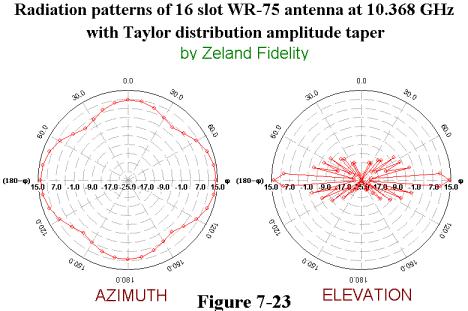
3 7.2.9 Waveguide size For most amateur bands, there are three usable sizes of standard waveguide: a small one where the ham band is near the low end of the waveguide recommended frequency range, a large one where the ham band is near the high end of the range, and an intermediate one where the ham band is near the center of the range. At GHz, these sizes are WR-75, WR-112, and WR-90, respectively. When we calculated slot dimensions, we found that they were most critical for the smaller size waveguide, so that the larger size would be preferable from a construction standpoint. To make sure this was also true for performance, I made computer models for 16-slot antennas in WR-75 and WR-112 waveguide to compare to the WR-90 results in Figures 7-15 and With perfect dimensions, the calculated WR-75 antenna patterns shown in Figure 7-22, with uniform amplitude distribution, are similar to the WR-90 results in Figure 7-16, except for the slightly larger elevation sidelobes that we would expect due to larger slot spacing. Similarly, Figure 7-23, with a Taylordistribution amplitude taper, compares well with the WR-90 pattern in Figure 7-16.
4
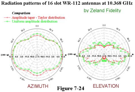
5 However, the WR-112 calculated antenna patterns are somewhat distorted, as shown in Figure The elevation patterns have large excess sidelobes, particularly below the horizontal plane, while the azimuth pattern also displays some assymetries. The three waveguide sizes are compared in Figure 7-25, showing the radiation patterns for 16-slot antennas with uniform amplitude taper. The WR-75 and WR-90 patterns are very similar, while the poor elevation patterns and unwanted azimuth directivity of the WR-112 patterns suffer in comparison. My hypothesis for the cause of the distortion in the large waveguide is that higher-order waveguide modes are excited at each slot. In the smaller waveguide, they are well beyond cutoff and so are rapidly attenuated before they reach the next slot. In the large waveguide, on the other hand, the higher-order modes are not attenuated as fast, and the slots are closer together, so some of the energy in the undesired mode may reach the next slot. Since different modes travel at different phase velocities, the undesired energy would have different phase and distort the pattern. A second problem, probably affecting the azimuth pattern, is that the large slot displacement from the centerline is a significant part of a wavelength, so that the array of slots no longer appears as a single vertical column, but rather two columns with a phase difference. Whatever the cause, the bottom line is that of three usable waveguide sizes for any given frequency, the smaller two are more likely to have predictable performance with perfect dimensions. Since the smallest size will have the most critical dimensional tolerances, we are most likely to get good results by constructing an antenna in the middle size waveguide, or WR-90 for 10 GHz.

6 The ideal omnidirectional waveguide slot antenna design would include all the elements we have seen thus far: 1. Use the standard waveguide size with the design frequency near the center of the recommended frequency range for the guide. 2. Minimize sidelobes in the elevation pattern with a Taylor distribution, achieved by tapering the slot displacement. 3. Add large wings to make the azimuth pattern more uniform. 4. Calculate dimensions with Elliott s improvements, using slotantenna.xls spreadsheet. At GHz, the best waveguide size would be WR Construction of waveguide slot antenna The ideal tool for cutting slots in waveguide is a milling machine a large, formidable piece of machinery. Most of us don t have one in the basement or garage. A milling machine is probably necessary to produce any quantity of slot antennas. However, if you are making just one or two, it is probably just as fast to do it by hand. The basic procedure for hand construction is straightforward: mark out the outlines of the slot locations carefully, drill of row of slightly undersize holes in each slot location, and file out the slots to the outline. Small random errors will tend to average out and not affect performance they might even smooth out the peaks and valleys in the azimuth pattern. Most waveguide is made of brass or aluminum, materials that are easy to work. Waveguide has also been made from copper, plated steel, and pure silver. All are more difficult to machine or file; the first two might be better put to other uses, and the latter should be sent to W1GHZ. The final step in construction is to solder on a short-circuit for the closed end and a waveguide flange on the input end. For brass waveguides, flux and a hot torch will do the job. Soldering aluminum is much more difficult, and I have never been happy with the results special materials and techniques are required, and the water-resistance of the final joint is questionable. At the lower microwave frequencies, real waveguide is hard to find, but rectangular aluminum extrusions intended for structural purposes may be used. K6LEW used some 4 x 1.5 inch aluminum extrusion stock as waveguide for a 2304 MHz slot antenna. For an even larger version at 23 cm, F4DAY and F9YA 23 sawed off one wall of a rectangular extrusion and taped two pieces together with aluminum tape to form a wider rectangle. The completed antenna, shown in Figure 7-26, is nearly as tall as Gerard. While it appears that he used hand tools, a woodworking router could also be used to quickly cut the large slots in soft aluminum.
7 Weatherproofing Weatherproofing is a problem for all antennas, but the open slots can easily fill the waveguide with water or insects. One approach that has been used successfully is to cover the slots with a thin tape of low-loss material, like kapton or mylar. The tape must be thin a thick dielectric will change the resonant frequency of the slots and raise the VSWR, so check the VSWR change when adding tape. Ultraviolet radiation from sunlight will deteriorate the tape over time, so it must be replaced periodically. Another approach is to enclose the slot antenna in a plastic tube. I can t recommend any particular type, so some experimentation is needed here. Again, if the enclosure changes the VSWR significantly, it is probably affecting the performance as well. WA5VJB suggested a third approach mount the antenna upside-down, fed from the top, so that water drains out. This probably works well in climates where water doesn t freeze and ice is only found in a glass! The short circuit, now at the bottom, need not seal the whole waveguide; in Figure 7-4, the very little electric field reaches the side walls, so the short circuit can be a wide strap across the center of the guide. The open corners will make little difference and allow water to drain out. Of course, we would like a beacon antenna to still work during a gullywasher; heavy rain can provide excellent rain-scatter propagation but could fill the antenna with flowing water. Some sort of open radome over the upside-down slot might be a winning combination. 7.3 Two-dimensional waveguide slot arrays A two-dimensional array of slots would have a narrowed beam in both azimuth and elevation, so it is a directional antenna. As such, it makes little sense to have slots on both sides of the waveguide. The equivalent dipole antenna is the old extended-expanded collinear by Oliver Wright, W6GD 24. A surplus slot antenna is shown in Figure 7-27, an array of 14 by 14 slots with the corners missing, for a total of 156 slots. From the slot dimensions, I estimate the operating frequency as about 9.2 GHz; the input VSWR is best near this frequency, with fairly narrow bandwidth. As we saw in section 7.2.8, it is likely that the bandwidth for good performance is also narrow. Moving the freqency would require changes to both slot length and spacing, so modification of this surplus antenna to 10 GHz is impractical. The array is fed by WR-90 waveguide, but the array is constructed of half-height waveguide, which decreases the slot displacement and makes dimensions more critical. The guides are formed by brazing thin walls between two thin sheets of aluminum, with the slots in the top sheet, so that the whole antenna only weighs about 500 grams, or just over a pound. With an automated punch press, it would be possible to make these arrays in volume, but I don t think they could ever be as cheap as the 18 inch DSS offset dishes, which retail for about $13.

8 The aperture diameter of the array is about 10λ, so it would be reasonable to expect the gain and beamwidth to be similar to a dish of 10λ diameter. The light weight, compact construction, and rear feed would make this an attractive alternative to the dish if one were available for an amateur band. The design procedure for a two-dimensional slot array is similar to the linear array above, with the additional complication of mutual coupling between the parallel slots. Elliott 22 has a good analysis for mutual coupling. The waveguide power divider is another issue, and the array in Figure 7-27 had a few tuning bumps brazed into the waveguide probably at locations found empirically. Measuring the slot dimensions provided some further insight into the design. The slot displacement was clearly tapered to provide a tapered amplitude distribution as described above, and the slot lengths also varied slightly, as would be necessary to compensate for the different displacements. This design clearly used the enhancement described previously. This antenna suggests that a tapered amplitude distribution for reduced sidelobes is useful in directional antennas. It could be applied just as well to large arrays of Yagi-Uda antennas reduced sidelobe levels with only a slight reduction in gain could result in a significant G/T improvement. However, the improvement is only significant for a fairly large array, with at least eight antennas in one direction.
Resonant Antennas: Wires and Patches
 Resonant Antennas: Wires and Patches Dipole Antennas Antenna 48 Current distribution approximation Un-normalized pattern: and Antenna 49 Radiating power: For half-wave dipole and,, or at exact resonance.
High-Power Directional Couplers with Excellent Performance That You Can Build
 High-Power Directional Couplers with Excellent Performance That You Can Build Paul Wade W1GHZ 2010 w1ghz@arrl.net A directional coupler is used to sample the RF energy travelling in a transmission line
Welcome to AntennaSelect Volume 10 May Optimizing VHF (Band III) Batwing antennas - Part 2
 Batwing antennas - Part 2") Welcome to AntennaSelect Volume 10 May 2014 Welcome to Volume 10 of our newsletter, AntennaSelect TM. Each month we will be giving you an under the radome look at antenna and RF technology. If there are
Welcome to AntennaSelect Volume 10 May 2014 Welcome to Volume 10 of our newsletter, AntennaSelect TM. Each month we will be giving you an under the radome look at antenna and RF technology. If there are
Practical Antennas and. Tuesday, March 4, 14
 Practical Antennas and Transmission Lines Goals Antennas are the interface between guided waves (from a cable) and unguided waves (in space). To understand the various properties of antennas, so as to
CHAPTER 5 PRINTED FLARED DIPOLE ANTENNA
 CHAPTER 5 PRINTED FLARED DIPOLE ANTENNA 5.1 INTRODUCTION This chapter deals with the design of L-band printed dipole antenna (operating frequency of 1060 MHz). A study is carried out to obtain 40 % impedance
Reflector Antenna, its Mount and Microwave. Absorbers for IIP Radiometer Experiments
 Reflector Antenna, its Mount and Microwave Absorbers for IIP Radiometer Experiments Nakasit Niltawach, and Joel T. Johnson May 8 th, 2003 1 Introduction As mentioned in [1], measurements are required for
ANTENNA INTRODUCTION / BASICS
 ANTENNA INTRODUCTION / BASICS RULES OF THUMB: 1. The Gain of an antenna with losses is given by: 2. Gain of rectangular X-Band Aperture G = 1.4 LW L = length of aperture in cm Where: W = width of aperture
Rec. ITU-R F RECOMMENDATION ITU-R F *
 Rec. ITU-R F.162-3 1 RECOMMENDATION ITU-R F.162-3 * Rec. ITU-R F.162-3 USE OF DIRECTIONAL TRANSMITTING ANTENNAS IN THE FIXED SERVICE OPERATING IN BANDS BELOW ABOUT 30 MHz (Question 150/9) (1953-1956-1966-1970-1992)
Chapter 5. Array of Star Spirals
 Chapter 5. Array of Star Spirals The star spiral was introduced in the previous chapter and it compared well with the circular Archimedean spiral. This chapter will examine the star spiral in an array
Traveling Wave Antennas
 Traveling Wave Antennas Antennas with open-ended wires where the current must go to zero (dipoles, monopoles, etc.) can be characterized as standing wave antennas or resonant antennas. The current on these
ANTENNA INTRODUCTION / BASICS
 Rules of Thumb: 1. The Gain of an antenna with losses is given by: G 0A 8 Where 0 ' Efficiency A ' Physical aperture area 8 ' wavelength ANTENNA INTRODUCTION / BASICS another is:. Gain of rectangular X-Band
Postwall waveguide slot array with cosecant radiation pattern and null filling for base station antennas in local multidistributed systems
 RADIO SCIENCE, VOL. 38, NO. 2, 8009, doi:10.1029/2001rs002580, 2003 Postwall waveguide slot array with cosecant radiation pattern and null filling for base station antennas in local multidistributed systems
Antenna Technology Bootcamp. NTA Show 2017 Denver, CO
 Antenna Technology Bootcamp NTA Show 2017 Denver, CO Review: How a slot antenna works The slot antenna is a TEM-Mode coaxial structure. Coupling structures inside the pylon will distort and couple to the
CHAPTER 2 MICROSTRIP REFLECTARRAY ANTENNA AND PERFORMANCE EVALUATION
 43 CHAPTER 2 MICROSTRIP REFLECTARRAY ANTENNA AND PERFORMANCE EVALUATION 2.1 INTRODUCTION This work begins with design of reflectarrays with conventional patches as unit cells for operation at Ku Band in
PRIME FOCUS FEEDS FOR THE COMPACT RANGE
 PRIME FOCUS FEEDS FOR THE COMPACT RANGE John R. Jones Prime focus fed paraboloidal reflector compact ranges are used to provide plane wave illumination indoors at small range lengths for antenna and radar
SAGE Millimeter, Inc.
 Description: Model SAM-5735930395-15-L1-4W is a linear polarized, 58 GHz microstrip patch 1 x 4 array antenna. The antenna array implements four individual antenna ports so that beamforming can be achieved
S.R.M. Institute of Science & Technology Deemed University School of Electronics & Communication Engineering
 S.R.M. Institute of Science & Technology Deemed University School of Electronics & Communication Engineering Question Bank Subject Code : EC401 Subject Name : Antennas and Wave Propagation Year & Sem :
Half-Wave Dipole. Radiation Resistance. Antenna Efficiency
 Antennas Simple Antennas Isotropic radiator is the simplest antenna mathematically Radiates all the power supplied to it, equally in all directions Theoretical only, can t be built Useful as a reference:
Antenna Basics. A general guide for antenna selection and installation techniques
 Antenna Basics A general guide for antenna selection and installation techniques Introduction to RF antennas What is an antenna, how does it work? An antenna is a metallic device that releases electromagnetic
Chapter 6 Antenna Basics. Dipoles, Ground-planes, and Wires Directional Antennas Feed Lines
 Chapter 6 Antenna Basics Dipoles, Ground-planes, and Wires Directional Antennas Feed Lines Some General Rules Bigger is better. (Most of the time) Higher is better. (Most of the time) Lower SWR is better.
3. LITERATURE REVIEW. 3.1 The Planar Inverted-F Antenna.
 3. LITERATURE REVIEW The commercial need for low cost and low profile antennas for mobile phones has drawn the interest of many researchers. While wire antennas, like the small helix and quarter-wavelength
Dr. John S. Seybold. November 9, IEEE Melbourne COM/SP AP/MTT Chapters
 Antennas Dr. John S. Seybold November 9, 004 IEEE Melbourne COM/SP AP/MTT Chapters Introduction The antenna is the air interface of a communication system An antenna is an electrical conductor or system
Antenna Theory and Design
 Antenna Theory and Design Antenna Theory and Design Associate Professor: WANG Junjun 王珺珺 School of Electronic and Information Engineering, Beihang University F1025, New Main Building wangjunjun@buaa.edu.cn
9 Element Yagi for 2304 MHz
 9 Element Yagi for 2304 MHz Steve Kavanagh, VE3SMA Design Dipole-based Yagi designs for 2304 MHz are rare, partly because they are a bit tricky to build and partly because the loop yagi has completely
Antenna Fundamentals Basics antenna theory and concepts
 Antenna Fundamentals Basics antenna theory and concepts M. Haridim Brno University of Technology, Brno February 2017 1 Topics What is antenna Antenna types Antenna parameters: radiation pattern, directivity,
Technician License. Course
 Technician License Course Technician License Course Chapter 4 Lesson Plan Module - 10 Practical Antennas The Dipole Most basic antenna The Dipole Most basic antenna The Dipole Total length is ½ wavelength
EEM.Ant. Antennas and Propagation
 EEM.ant/0304/08pg/Req: None 1/8 UNIVERSITY OF SURREY Department of Electronic Engineering MSc EXAMINATION EEM.Ant Antennas and Propagation Duration: 2 Hours Spring 2003/04 READ THESE INSTRUCTIONS Answer
Antennas and Propagation Chapters T4, G7, G8 Antenna Fundamentals, More Antenna Types, Feed lines and Measurements, Propagation
 Antennas and Propagation Chapters T4, G7, G8 Antenna Fundamentals, More Antenna Types, Feed lines and Measurements, Propagation =============================================================== Antenna Fundamentals
CHAPTER 5 THEORY AND TYPES OF ANTENNAS. 5.1 Introduction
 CHAPTER 5 THEORY AND TYPES OF ANTENNAS 5.1 Introduction Antenna is an integral part of wireless communication systems, considered as an interface between transmission line and free space [16]. Antenna
stacking broadside collinear
 stacking broadside collinear There are three primary types of arrays, collinear, broadside, and endfire. Collinear is pronounced co-linear, and we may think it is spelled colinear, but the correct spelling
Chapter 3 Broadside Twin Elements 3.1 Introduction
 Chapter 3 Broadside Twin Elements 3. Introduction The focus of this chapter is on the use of planar, electrically thick grounded substrates for printed antennas. A serious problem with these substrates
6.9.6 Dual-band feed experiments
 6.9.6 Dual-band feed experiments I was impressed with the performance of the dual-band feeds for 10 and 24 GHz; I hypothesized that the wider frequency separation might provide better results than the
Notes 21 Introduction to Antennas
 ECE 3317 Applied Electromagnetic Waves Prof. David R. Jackson Fall 018 Notes 1 Introduction to Antennas 1 Introduction to Antennas Antennas An antenna is a device that is used to transmit and/or receive
"Natural" Antennas. Mr. Robert Marcus, PE, NCE Dr. Bruce C. Gabrielson, NCE. Security Engineering Services, Inc. PO Box 550 Chesapeake Beach, MD 20732
 Published and presented: AFCEA TEMPEST Training Course, Burke, VA, 1992 Introduction "Natural" Antennas Mr. Robert Marcus, PE, NCE Dr. Bruce C. Gabrielson, NCE Security Engineering Services, Inc. PO Box
Broadband Antenna. Broadband Antenna. Chapter 4
 1 Chapter 4 Learning Outcome At the end of this chapter student should able to: To design and evaluate various antenna to meet application requirements for Loops antenna Helix antenna Yagi Uda antenna
High gain W-shaped microstrip patch antenna
 High gain W-shaped microstrip patch antenna M. N. Shakib 1a),M.TariqulIslam 2, and N. Misran 1 1 Department of Electrical, Electronic and Systems Engineering, Universiti Kebangsaan Malaysia (UKM), UKM
4/29/2012. General Class Element 3 Course Presentation. Ant Antennas as. Subelement G9. 4 Exam Questions, 4 Groups
 General Class Element 3 Course Presentation ti ELEMENT 3 SUB ELEMENTS General Licensing Class Subelement G9 Antennas and Feedlines 4 Exam Questions, 4 Groups G1 Commission s Rules G2 Operating Procedures
THE HENTENNA RE-VISITED
 THE HENTENNA RE-VISITED "The following article has been re-edited for the English language from the Japanese site. Minor errors and corrections have been made." The Hentenna was developed by Japanese 6
Antenna Design Seminar
 Antenna Design Seminar What we are going to cover This seminar will cover the design concepts of a variety of broadcast antennas that relates to the design of TV and FM antennas. We will first look at
Reflector antennas and their feeds
 Reflector antennas and their feeds P. Hazdra, M. Mazanek,. hazdrap@fel.cvut.cz Department of Electromagnetic Field Czech Technical University in Prague, FEE www.elmag.org v. 23.4.2015 Outline Simple reflector
Circularly Polarized Post-wall Waveguide Slotted Arrays
 Circularly Polarized Post-wall Waveguide Slotted Arrays Hisahiro Kai, 1a) Jiro Hirokawa, 1 and Makoto Ando 1 1 Department of Electrical and Electric Engineering, Tokyo Institute of Technology 2-12-1 Ookayama
ANTENNAS. I will mostly be talking about transmission. Keep in mind though, whatever is said about transmission is true of reception.
 Reading 37 Ron Bertrand VK2DQ http://www.radioelectronicschool.com ANTENNAS The purpose of an antenna is to receive and/or transmit electromagnetic radiation. When the antenna is not connected directly
Compact Microstrip Magnetic Yagi Antenna and Array with Vertical Polarization Based on Substrate Integrated Waveguide
 Progress In Electromagnetics Research C, Vol. 59, 135 141, 215 Compact Microstrip Magnetic Yagi Antenna and Array with Vertical Polarization Based on Substrate Integrated Waveguide Zhao Zhang *, Xiangyu
Antenna Fundamentals
 HTEL 104 Antenna Fundamentals The antenna is the essential link between free space and the transmitter or receiver. As such, it plays an essential part in determining the characteristics of the complete
Microwave Antennas making the world smaller
 Microwave Antennas making the world smaller www.procom.dk Index MICROWAVE ANTENNAS 10 GHz Omnidirectional Antennas WGSL 10 2 Parabolic Antennas PRO-10-001/25 3 PRO-10-001/50 4 Accessories PRO-10-... 5
Transforms and electrical signal into a propagating electromagnetic wave OR vise versa. - Transducer goes both ways. TX and RX antennas have
 Gary Rondeau AF7NX Transforms and electrical signal into a propagating electromagnetic wave OR vise versa. - Transducer goes both ways. TX and RX antennas have different jobs. For TX want to generate as
Design and Development of Ultralow Sidelobe Antenna
 Defence Science Journal, Vol49, No 1, January 1999, pp. 49-54 0 1999, DESIDOC Design and Development of Ultralow Sidelobe Antenna S. Christopher and V. V. S. Prakash Electronics & Radar Development Establishment,
4.4. Experimental Results and Analysis
 4.4. Experimental Results and Analysis 4.4.1 Measurement of the IFA Against a Large Ground Plane The Inverted-F Antenna (IFA) discussed in Section 4.3.1 was modeled over an infinite ground plane using
Newsletter 5.4. New Antennas. The profiled horns. Antenna Magus Version 5.4 released! May 2015
 Newsletter 5.4 May 215 Antenna Magus Version 5.4 released! Version 5.4 sees the release of eleven new antennas (taking the total number of antennas to 277) as well as a number of new features, improvements
UNIVERSITI MALAYSIA PERLIS
 UNIVERSITI MALAYSIA PERLIS SCHOOL OF COMPUTER & COMMUNICATIONS ENGINEERING EKT 341 LABORATORY MODULE LAB 2 Antenna Characteristic 1 Measurement of Radiation Pattern, Gain, VSWR, input impedance and reflection
LE/ESSE Payload Design
 LE/ESSE4360 - Payload Design 4.3 Communications Satellite Payload - Hardware Elements Earth, Moon, Mars, and Beyond Dr. Jinjun Shan, Professor of Space Engineering Department of Earth and Space Science
Chapter 7 - Experimental Verification
 Chapter 7 - Experimental Verification 7.1 Introduction This chapter details the results of measurements from several experimental prototypes of Stub Loaded Helix antennas that were built and tested. Due
Band I (Low VHF) TV Panel Arrays MHz. 606L Series BROADCAST ANTENNA SYSTEMS
 TV Panel Arrays MHz. 606L Series BROADCAST ANTENNA SYSTEMS") Band I (Low VHF) TV Panel Arrays 44-88 MHz L Series The L series of panels are low wind load antennas suitable to provide a customized coverage for any single TV channel in Band I. Low wind load Pressurizable
Band I (Low VHF) TV Panel Arrays 44-88 MHz L Series The L series of panels are low wind load antennas suitable to provide a customized coverage for any single TV channel in Band I. Low wind load Pressurizable
360 inches (915 cm) 240 inches (610 cm) 120 inches (305 cm) 240 inches is the recommended pole length, 360 inches is the recommended free space area
 240 inches (610 cm) 120 inches (305 cm) 240 inches is the recommended pole length, 360 inches is the recommended free space area") FML C/P FM Antenna Right hand C/P Polarization Low wind load area Up to 1 kw Rating per bay Omni-directional Up to 8 kw input per array with power divider options The FML series of antennas are narrow
FML C/P FM Antenna Right hand C/P Polarization Low wind load area Up to 1 kw Rating per bay Omni-directional Up to 8 kw input per array with power divider options The FML series of antennas are narrow
W1GHZ W1GHZ W1GHZ W1GHZ W1GHZ W1GHZ W1GHZ W1GHZ
 Online Online Online Online Online Online (ex-n1bwt) (ex-n1bwt) (ex-n1bwt) (ex-n1bwt) (ex-n1bwt) (ex-n1bwt) (ex-n1bwt) Online (ex-n1bwt) W1GHZ W1GHZ Microwave Antenna Book Antenna BookOnline W1GHZ W1GHZ
Newsletter 4.4. Antenna Magus version 4.4 released! Array synthesis reflective ground plane addition. July 2013
 Newsletter 4.4 July 2013 Antenna Magus version 4.4 released! We are pleased to announce the new release of Antenna Magus Version 4.4. This release sees the addition of 5 new antennas: Horn-fed truncated
Design and Development of a 2 1 Array of Slotted Microstrip Line Fed Shorted Patch Antenna for DCS Mobile Communication System
 Wireless Engineering and Technology, 2013, 4, 59-63 http://dx.doi.org/10.4236/wet.2013.41009 Published Online January 2013 (http://www.scirp.org/journal/wet) 59 Design and Development of a 2 1 Array of
DESIGN OF PRINTED YAGI ANTENNA WITH ADDI- TIONAL DRIVEN ELEMENT FOR WLAN APPLICA- TIONS
 Progress In Electromagnetics Research C, Vol. 37, 67 81, 013 DESIGN OF PRINTED YAGI ANTENNA WITH ADDI- TIONAL DRIVEN ELEMENT FOR WLAN APPLICA- TIONS Jafar R. Mohammed * Communication Engineering Department,
UNIT Write short notes on travelling wave antenna? Ans: Travelling Wave Antenna
 UNIT 4 1. Write short notes on travelling wave antenna? Travelling Wave Antenna Travelling wave or non-resonant or aperiodic antennas are those antennas in which there is no reflected wave i.e., standing
Antennas 1. Antennas
 Antennas Antennas 1! Grading policy. " Weekly Homework 40%. " Midterm Exam 30%. " Project 30%.! Office hour: 3:10 ~ 4:00 pm, Monday.! Textbook: Warren L. Stutzman and Gary A. Thiele, Antenna Theory and
Electronically Steerable planer Phased Array Antenna
 Electronically Steerable planer Phased Array Antenna Amandeep Kaur Department of Electronics and Communication Technology, Guru Nanak Dev University, Amritsar, India Abstract- A planar phased-array antenna
Development of a noval Switched Beam Antenna for Communications
 Master Thesis Presentation Development of a noval Switched Beam Antenna for Communications By Ashraf Abuelhaija Supervised by Prof. Dr.-Ing. Klaus Solbach Institute of Microwave and RF Technology Department
Chapter 5. Numerical Simulation of the Stub Loaded Helix
 Chapter 5. Numerical Simulation of the Stub Loaded Helix 5.1 Stub Loaded Helix Antenna Performance The geometry of the Stub Loaded Helix is significantly more complicated than that of the conventional
BHARATHIDASAN ENGINEERING COLLEGE NATTARAMPALLI Frequently Asked Questions (FAQ) Unit 1
 Unit 1") BHARATHIDASAN ENGINEERING COLLEGE NATTARAMPALLI 635854 Frequently Asked Questions (FAQ) Unit 1 Degree / Branch : B.E / ECE Sem / Year : 3 rd / 6 th Sub Name : Antennas & Wave Propagation Sub Code : EC6602
BHARATHIDASAN ENGINEERING COLLEGE NATTARAMPALLI 635854 Frequently Asked Questions (FAQ) Unit 1 Degree / Branch : B.E / ECE Sem / Year : 3 rd / 6 th Sub Name : Antennas & Wave Propagation Sub Code : EC6602
A DUAL-PORTED PROBE FOR PLANAR NEAR-FIELD MEASUREMENTS
 A DUAL-PORTED PROBE FOR PLANAR NEAR-FIELD MEASUREMENTS W. Keith Dishman, Doren W. Hess, and A. Renee Koster ABSTRACT A dual-linearly polarized probe developed for use in planar near-field antenna measurements
Shortened 3D Corner Reflector Antenna Dragoslav Dobričić, YU1AW
 Shortened 3D Corner Reflector Antenna Dragoslav Dobričić, YU1AW Abstract In this text two 3D corner reflector antenna modifications are described. The first modification is regarding the input impedance
L-BAND COPLANAR SLOT LOOP ANTENNA FOR INET APPLICATIONS
 L-BAND COPLANAR SLOT LOOP ANTENNA FOR INET APPLICATIONS Jeyasingh Nithianandam Electrical and Computer Engineering Department Morgan State University, 500 Perring Parkway, Baltimore, Maryland 5 ABSTRACT
A NEW TECHNIQUE FOR CONSTRUCTION OF 23CM SEPTUM FEED June 18, 2010 (Revised November 15, 2017)
") INTRODUCTION 1296 MHz EME popularity is growing this band seems to be the big attraction these days. Just acquire an old TVRO dish and you are on your way. This article will hopefully at least make the
INTRODUCTION 1296 MHz EME popularity is growing this band seems to be the big attraction these days. Just acquire an old TVRO dish and you are on your way. This article will hopefully at least make the
4 Antennas as an essential part of any radio station
 4 Antennas as an essential part of any radio station 4.1 Choosing an antenna Communicators quickly learn two antenna truths: Any antenna is better than no antenna. Time, effort and money invested in the
Improved Ionospheric Propagation With Polarization Diversity, Using A Dual Feedpoint Cubical Quad Loop
 Improved Ionospheric Propagation With Polarization Diversity, Using A Dual Feedpoint Cubical Quad Loop by George Pritchard - AB2KC ab2kc@optonline.net Introduction This Quad antenna project covers a practical
Accuracy Estimation of Microwave Holography from Planar Near-Field Measurements
 Accuracy Estimation of Microwave Holography from Planar Near-Field Measurements Christopher A. Rose Microwave Instrumentation Technologies River Green Parkway, Suite Duluth, GA 9 Abstract Microwave holography
EMG4066:Antennas and Propagation Exp 1:ANTENNAS MMU:FOE. To study the radiation pattern characteristics of various types of antennas.
 OBJECTIVES To study the radiation pattern characteristics of various types of antennas. APPARATUS Microwave Source Rotating Antenna Platform Measurement Interface Transmitting Horn Antenna Dipole and Yagi
CHAPTER 8 ANTENNAS 1
 CHAPTER 8 ANTENNAS 1 2 Antennas A good antenna works A bad antenna is a waste of time & money Antenna systems can be very inexpensive and simple They can also be very expensive 3 Antenna Considerations
Travelling Wave, Broadband, and Frequency Independent Antennas. EE-4382/ Antenna Engineering
 Travelling Wave, Broadband, and Frequency Independent Antennas EE-4382/5306 - Antenna Engineering Outline Traveling Wave Antennas Introduction Traveling Wave Antennas: Long Wire, V Antenna, Rhombic Antenna
Antenna Fundamentals. Microwave Engineering EE 172. Dr. Ray Kwok
 Antenna Fundamentals Microwave Engineering EE 172 Dr. Ray Kwok Reference Antenna Theory and Design Warran Stutzman, Gary Thiele, Wiley & Sons (1981) Microstrip Antennas Bahl & Bhartia, Artech House (1980)
The Basics of Patch Antennas, Updated
 The Basics of Patch Antennas, Updated By D. Orban and G.J.K. Moernaut, Orban Microwave Products www.orbanmicrowave.com Introduction This article introduces the basic concepts of patch antennas. We use
Aperture Antennas. Reflectors, horns. High Gain Nearly real input impedance. Huygens Principle
 Antennas 97 Aperture Antennas Reflectors, horns. High Gain Nearly real input impedance Huygens Principle Each point of a wave front is a secondary source of spherical waves. 97 Antennas 98 Equivalence
Antennas & Transmission Lines
 Antennas & Transmission Lines Network Startup Resource Center www.nsrc.org These materials are licensed under the Creative Commons Attribution-NonCommercial 4.0 International license (http://creativecommons.org/licenses/by-nc/4.0/)
The magnetic surface current density is defined in terms of the electric field at an aperture as follows: 2E n (6.1)
") Chapter 6. Aperture antennas Antennas where radiation occurs from an open aperture are called aperture antennas. xamples include slot antennas, open-ended waveguides, rectangular and circular horn antennas,
Chapter 6. Aperture antennas Antennas where radiation occurs from an open aperture are called aperture antennas. xamples include slot antennas, open-ended waveguides, rectangular and circular horn antennas,
RECOMMENDATION ITU-R BS.80-3 * Transmitting antennas in HF broadcasting
 Rec. ITU-R BS.80-3 1 RECOMMENDATION ITU-R BS.80-3 * Transmitting antennas in HF broadcasting (1951-1978-1986-1990) The ITU Radiocommunication Assembly, considering a) that a directional transmitting antenna
Introduction Antenna Ranges Radiation Patterns Gain Measurements Directivity Measurements Impedance Measurements Polarization Measurements Scale
 Chapter 17 : Antenna Measurement Introduction Antenna Ranges Radiation Patterns Gain Measurements Directivity Measurements Impedance Measurements Polarization Measurements Scale Model Measurements 1 Introduction
General License Class Chapter 6 - Antennas. Bob KA9BHD Eric K9VIC
 General License Class Chapter 6 - Antennas Bob KA9BHD Eric K9VIC Learning Objectives Teach you enough to get all the antenna questions right during the VE Session Learn a few things from you about antennas
Design of an Airborne SLAR Antenna at X-Band
 Design of an Airborne SLAR Antenna at X-Band Markus Limbach German Aerospace Center (DLR) Microwaves and Radar Institute Oberpfaffenhofen WFMN 2007, Markus Limbach, Folie 1 Overview Applications of SLAR
Yagi Antenna Tutorial. Copyright K7JLT 1
 Yagi Antenna Tutorial Copyright K7JLT Yagi: The Man & Developments In the 920 s two Japanese electrical engineers, Hidetsugu Yagi and Shintaro Uda at Tohoku University in Sendai Japan, investigated ways
ENHANCEMENT OF PHASED ARRAY SIZE AND RADIATION PROPERTIES USING STAGGERED ARRAY CONFIGURATIONS
 Progress In Electromagnetics Research C, Vol. 39, 49 6, 213 ENHANCEMENT OF PHASED ARRAY SIZE AND RADIATION PROPERTIES USING STAGGERED ARRAY CONFIGURATIONS Abdelnasser A. Eldek * Department of Computer
EC ANTENNA AND WAVE PROPAGATION
 EC6602 - ANTENNA AND WAVE PROPAGATION FUNDAMENTALS PART-B QUESTION BANK UNIT 1 1. Define the following parameters w.r.t antenna: i. Radiation resistance. ii. Beam area. iii. Radiation intensity. iv. Directivity.
End Fed vs. Center Fed Slotted Coaxial Broadcast Antenna. Not a Choice of Preference
 End Fed vs. Center Fed Slotted Coaxial Broadcast Antenna Not a Choice of Preference John L. Schadler VP Engineering Dielectric Raymond, ME. Abstract The advantages of center feeding a slotted coaxial,
In this lecture, we study the general case of radiation from z-directed spatial currents. The far-
 In this lecture, we study the general case of radiation from z-directed spatial currents. The far- field radiation equations that result from this treatment form some of the foundational principles of
WHITE PAPER. Hybrid Beamforming for Massive MIMO Phased Array Systems
 WHITE PAPER Hybrid Beamforming for Massive MIMO Phased Array Systems Introduction This paper demonstrates how you can use MATLAB and Simulink features and toolboxes to: 1. Design and synthesize complex
Performance Analysis of a Patch Antenna Array Feed For A Satellite C-Band Dish Antenna
 Cyber Journals: Multidisciplinary Journals in Science and Technology, Journal of Selected Areas in Telecommunications (JSAT), November Edition, 2011 Performance Analysis of a Patch Antenna Array Feed For
A 6-Meter Quad-Turnstile
 By L. B. Cebik, W4RNL A 6-Meter Quad-Turnstile Looking for improved omnidirectional, horizontally polarized performance? This 6-meter turnstile uses the quad loop as a foundation. Turnstile Principles
INSTITUTE OF AERONAUTICAL ENGINEERING Dundigal, Hyderabad ELECTRONICS AND COMMUNIACTION ENGINEERING QUESTION BANK
 INSTITUTE OF AERONAUTICAL ENGINEERING Dundigal, Hyderabad - 500 04 ELECTRONICS AND COMMUNIACTION ENGINEERING QUESTION BANK Course Name : Antennas and Wave Propagation (AWP) Course Code : A50418 Class :
ANTENNAS FEED POINTS. An antenna is a mechanical structure by which electromagnetic waves are sent out or received.
 ANTENNAS An antenna is a mechanical structure by which electromagnetic waves are sent out or received. An antenna accomplishes this by being made so that its structure will be resonant at the frequency
Radiation Analysis of Phased Antenna Arrays with Differentially Feeding Networks towards Better Directivity
 Radiation Analysis of Phased Antenna Arrays with Differentially Feeding Networks towards Better Directivity Manohar R 1, Sophiya Susan S 2 1 PG Student, Department of Telecommunication Engineering, CMR
Design and Simulation of Dipole and Cable-Fed Network of TD-SCDMA Smart Antenna 1
 2009 International Conference on Communications and Mobile Computing Design and Simulation of Dipole and Cable-Fed Network of TD-SCDMA Smart Antenna 1 Maowen Wang 1, Yejun He 1,2,3, Guangxi Zhu 2, Deming
Cisco Aironet Six-Element Dual-Band MIMO Patch Array Antenna (AIR-ANT25137NP-R)
") Cisco Aironet Six-Element Dual-Band MIMO Patch Array Antenna (AIR-ANT25137NP-R) August 2, 2013 This document describes the AIR-ANT25137NP-R antenna and provides instructions for mounting it. The antenna
Cisco Aironet Six-Element Dual-Band MIMO Patch Array Antenna (AIR-ANT25137NP-R) August 2, 2013 This document describes the AIR-ANT25137NP-R antenna and provides instructions for mounting it. The antenna
Antennas Demystified Antennas in Emergency Communications. Scott Honaker N7SS
 Antennas Demystified Antennas in Emergency Communications Scott Honaker N7SS Importance of Antennas Antennas are more important than the radio A $5000 TV with rabbit ears will have a lousy picture Antennas
Planar Radiators 1.1 INTRODUCTION
 1 Planar Radiators 1.1 INTRODUCTION The rapid development of wireless communication systems is bringing about a wave of new wireless devices and systems to meet the demands of multimedia applications.
Welcome to AntennaSelect Volume 34 October UHF and VHF Stacked Antenna Pylons
 Welcome to AntennaSelect Volume 34 October 2017 Welcome to Volume 34 of our newsletter, AntennaSelect TM. Every two months we will be giving you an under the radome look at antenna and RF Technology. If
Chapter 7 Design of the UWB Fractal Antenna
 Chapter 7 Design of the UWB Fractal Antenna 7.1 Introduction F ractal antennas are recognized as a good option to obtain miniaturization and multiband characteristics. These characteristics are achieved