Power System Neutral/Ground Voltages Causes, Safety Concerns and Mitigation
|
|
|
- Magnus McLaughlin
- 5 years ago
- Views:
Transcription
1 Power System Neutral/Ground Voltages Causes, Safety Concerns and Mitigation A. P. Sakis Meliopoulos Georgia Institute of Technology September 7, 2004 Tele-Seminar 2004 A. P. Sakis Meliopoulos 1
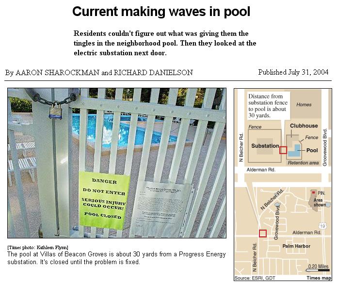
2 Power System Design Principles for Safety Any Individual Should be Safe in the Vicinity of an Electrical Installation An Individual Touching ANY Grounded Structure Should be Safe Under All Foreseeable Adverse Conditions Electrical System Installations Should be Designed so that Meet Above Requirements Yet, we read in in the papers 2
3 3
4 4
5 5
6 6
7 7
8 Fundamental Facts Humans are susceptible to even low electric currents Perception: 1 ma, ma, Let Let Go Go ma, ma, Ventricular Fibrilation ma mafor for 3 seconds Several Physical Phenomena will Result in Elevated Voltages of the Neutral of Electrical Installations and Interconnected or not Connected Grounds Ground Faults System Imbalance High High Impedance Ground Faults 8
9 Safety Perception Current Let-Go Current Ventricular Fibrillation Percentile Rank Predicted Curve for Women Men Perception Currrent, ma (RMS) Let-Go Current (Milliamperes) - RMS % Dangerous Current 50% 0.5% Let-Go Threshold Safe Current Frequency (Hz) Fibrillating Current (ma RMS) Kiselev Dogs Dogs Ferris Dogs sheep calves pigs Minimum Fibrillating Current (0.5%) Maximum Non-Fibrillating Current (0.5%) ody Weight (kg) 9
10 ody Impedance Dependence on Voltage - CEI-1984 Total ody Impedance Z T Values for the total body impedance (Ohms) that are not exceeded for a percentage (percentile rank) of Touch Voltage 5% of the population 50% of the population 95% of the population Asymptotic Value
11 Important Facts Humans: About 2 Volts of Touch Voltage Will Result in Perception of Electrtic Shock. Much Lower for Kids Chicken: About 0.9 Volts of Voltage Will Make Chickens Stay Away Importance??? Claims of Stray Voltage Effects on Cows and Fish Have een Very Serious and Fiercely Litigated Continuous Voltages of 30 to 60 Volts Have Resulted in Fatalities of Humans and Animals 11
12 Earth Current / Ground Potential Rise / Safety A V A A V A V A A US10 US20 US30 US40 L R G Program XFM - Page 1 of 1 c:\w m aster\igs\datau\gpr_ex01 - May 14, 2000, 01:51: sam ples/sec Sam ples Phase_A_Line_Current US10 (ka) V V V A A A m m m Earth_Current Ground_at_US20 (ka) m m m m m m Important Issues Ground Potential Rise Changes Neutral Voltage Customer Voltage is Proportional to Phase to Neutral Voltage Grounding and onding Single Ground/Multi Ground Transmission Interconnection 12

13 Safety Assessment 3-D D Graph of Touch Voltages In a Substation 13
14 The IEEE Std 80 Addresses Safety in Utility Substation. In this talk, we will not discuss safety during HV faults. It Is important to mention that because the grounding system is continuous, a high voltage elevation of the substation ground will propagate through the neutral and reach residences, pools, offices, etc. 14

15 Stray Voltages in Overhead Distribution Circuits Generation Mechanism 15
16 Neutral Voltages Under Normal Operation G Vn = mv SOURCE1 115 kv Source Z1=Z2=j0.084 Z0=j0.066 Yellowjacket Substation 30 MVA XFMR Three 5 kw Loads on Phase A-N Soil Resistivity: 100 Ohm-Meters Transformer Grounding Resistor: 20 Ohms 1 2 Vn = mv Vn = V Vn = V SU1 SU2 POLE1 Vn = V POLE2 Vnn = V POLE3 Vn = V POLE4 Vnn = V POLE5 Vnn = V HOUSE2 Grounding Model G Vn = mv SOURCE2 115 kv Source Z1=Z2=j0.102 Z0=j

17 Shock Hazard 17

18 Pool Electrical Equipment Wiring 18
19 Line Touching Case Permanent Ground Fault 19
20 Can These Phenomena e Simulated? Grounding, Safety and Neutral Voltage Analysis Requires: Physically-ased Detailed-Models 20
21 Why Physically ased Models? Consider Actual Wiring and Grounding ~ I sky Sky Wire HA H HC Neutral LA L LC Circuits are Asymmetric Phase Voltages Vary Ground Mat Counterpoise Ground Rod Ground Rod ~ I counterpoise ~ I earth ~ I neutral CATV Circuits Are Unbalanced Phase Voltages Vary Finite Ground Impedances NonZero Neutral Voltages Customer Phase to Neutral Voltage 21
22 Physically ased Models Example: Three Phase Power Line Physically ased Model Neutral is Represented Asymmetry is Represented 1 3.5' A1 C1 N1 Sequence Parameter Model Neutral is Lost Asymmetry is Lost Transmission Line Sequence Networks Close Positive Sequence Network j All Values in Ohms j j feet Negative Sequence Network j j j Zero Sequence Network j j j S. POLE DISTRI. LINE (TRIANGLE)/ 12 KV Program WinIGS - Form OHL_REP2 22
 d + (2nD + z zc ) I 1 n K + 4πσ 2 2 2 2 1 n= 1 d + (2nD z + zc ) d + (2nD z zc ) 1 1 1 23")
23 Ground Modeling The Method of Images (Two Layer Soil) Reflection Coefficient K = σ σ 1 1 σ + σ 2 2 V = + I n K + 4πσ n= 0 d + (2nD + z + zc ) d + (2nD + z zc ) I 1 n K + 4πσ n= 1 d + (2nD z + zc ) d + (2nD z zc )
24 G Computer Generated Example 1 Neutral Voltages Under Normal Operation Vn = mv SOURCE1 115 kv Source Z1=Z2=j0.084 Z0=j0.066 Yellowjacket Substation 30 MVA XFMR Three 5 kw Loads on Phase A-N Soil Resistivity: 100 Ohm-Meters Transformer Grounding Resistor: 200 Ohms 1 2 Vn = mv Vn = V Vn = V SU1 SU2 POLE1 Vn = V POLE2 Vnn = V POLE3 Vn = V POLE4 Vnn = V POLE5 Vnn = V HOUSE2 Grounding Model G Vn = mv SOURCE2 115 kv Source Z1=Z2=j0.102 Z0=j


25 Earth Surface Voltages Under Normal Operation 25
26 Computer Generated Example 2 Faults on Low Voltage Underground Distribution Circuit 26

27 Line Touching Case 27
28 Neutral Voltages Under Normal Operation G US0001 G US0002 US0003 VL1-NN = V VL2-NN = V Vnn = mv US0005 VL1-NN = V VL2-NN = V Vnn = mv US0007 VL1-NN = V VL2-NN = V Vnn = mv US0006 US0004 VL1-NN = V VL2-NN = V Vnn = mv US0014 VL1-NN = V VL2-NN = V Vnn = mv US0012 VL1-NN = V VL2-NN = V Vnn = mv US0015 VL1-NN = V VL1-NN = V VL2-NN = V VL1-NN = V VL2-NN = V Vgg = mv VL2-NN = V Vnn = mv Vnn = mv Vnn = mv US0008 US0009 US0013 US0011 US0010 Ground Model VL1-NN = V VL2-NN = V Fault Model Vgg = mv Vgg = V Vnn = V US0017 US0016 1Ph 28
29 Neutral Voltages During Permanent Fault G US0001 G US0002 US0003 VL1-NN = V VL2-NN = V Vnn = V US0005 VL1-NN = V VL2-NN = V Vnn = V US0007 VL1-NN = V VL2-NN = V Vnn = V US0006 US0004 VL1-NN = V VL2-NN = V Vnn = V US0014 VL1-NN = V VL2-NN = V Vnn = V US0012 VL1-NN = V VL2-NN = V Vnn = V US0015 VL1-NN = V VL1-NN = V VL2-NN = V VL1-NN = V VL2-NN = V Vgg = V VL2-NN = V Vnn = V Vnn = V Vnn = V US0008 US0009 US0013 US0011 US0010 Ground Model VL1-NN = V VL2-NN = V Fault Model Vgg = V Vgg = V Vnn = V US0017 US0016 1Ph 29


30 Earth Surface Voltages During Fault 30
31 Detection of Stray Voltages Many approaches are being pursued Mitigation of Stray Voltages Minimize system imbalance Improve Grounds/neutrals Avoidance of Neutral/Ground Voltages from Permanent Faults Improve grounds Provide ground fault protection Need to re-design some old systems Avoid same design mistakes in new systems 31
32 G Vn = mv SOURCE1 115 kv Source Example of Neutral Voltages Mitigation Electric Loads Line-to-Line Z1=Z2=j0.084 Z0=j0.066 Yellowjacket Substation 30 MVA XFMR Three 5 kw Loads on Phase A- Soil Resistivity: 100 Ohm-Meters Transformer Grounding Resistor: 200 Ohms 1 2 Vn = mv Vn = mv Vn = mv SU1 SU2 POLE1 Vn = mv POLE2 Vnn = mv POLE3 Vn = mv POLE4 Vnn = mv POLE5 Vnn = mv HOUSE2 Grounding Model G Vn = mv SOURCE2 115 kv Source Z1=Z2=j0.102 Z0=j
33 For more in-depth information Integrated Grounding System Design and Testing Grounding, Harmonics, & Electromagnetic Influence Design Practices Power Distribution System Grounding and Transients March 22-25, 2005 May 16-18, 2005 September 21-23,
34 Conclusions Elevated voltages in neutrals and grounds is reality. Proper design practices can mitigate these voltages. Physically based modeling provides the basis to study simultaneously grounding, neutral voltages and safety. Disadvantage: More Complex Models. Observation: Electric power installations can be designed to be safe at low cost. Retrofitting is relatively expensive. However, there is a substantial percentage of the industry that does not pay attention to this issue at the design phase. 34
35 Τελος 35
SAFETY ISSUES RELATED TO THE CONNECTION OF MV AND HV GROUNDING
 SAFETY ISSUES RELATED TO THE CONNECTION OF MV AND HV GROUNDING Y. Rajotte J. Fortin G. Lessard Hydro-Québec, Canada Hydro-Québec, Canada Hydro-Québec, Canada e-mails: rajotte.yves@ireq.ca fortin.jacques@ireq.ca
The Confusion Surrounding Stray Voltage
 The Confusion Surrounding Stray Voltage Jim Burke, InfraSource Inc., Fellow, IEEE Abstract While stray voltage has been a concern for farm livestock for many years, it is only within the past few years
Industrial and Commercial Power Systems Topic 7 EARTHING
 The University of New South Wales School of Electrical Engineering and Telecommunications Industrial and Commercial Power Systems Topic 7 EARTHING 1 INTRODUCTION Advantages of earthing (grounding): Limitation
Single Earthed Neutral and Multi Earthed Neutral. Single Earthed Neutral and Multi Earthed Neutral: Multi Grounded Neutral System (MEN):
:") Single Earthed Neutral and Multi Earthed Neutral. SEPTEMBER 6, 2011 5 COMMENTS Single Earthed Neutral and Multi Earthed Neutral: In Distribution System Three Phase load is unbalance and non linear so The
Single Earthed Neutral and Multi Earthed Neutral. SEPTEMBER 6, 2011 5 COMMENTS Single Earthed Neutral and Multi Earthed Neutral: In Distribution System Three Phase load is unbalance and non linear so The
Grounding for Power Quality
 Presents Grounding for Power Quality Grounding for Power Quality NEC 250.53 states that ground resistance should be less than 25 ohms. Is this true? Grounding for Power Quality No! NEC 250.53 states
PRACTICAL PROBLEMS WITH SUBSTATION EARTHING
 1 PRACTICAL PROBLEMS WITH SUBSTATION EARTHING Dr Hendri Geldenhuys Craig Clark Eskom Distribution Technology This paper considers the issues around substation sites where the soil resistivity is of particularly
WinIGS. Windows Based Integrated Grounding System Design Program. Training Guide. Last Revision: June 2017
 WinIGS Windows Based Integrated Grounding System Design Program Training Guide Last Revision: June 2017 Copyright A. P. Sakis Meliopoulos 2017 NOTICES Copyright Notice This document may not be reproduced
EVALUATION OF DIFFERENT SOLUTIONS OF FAULTED PHASE EARTHING TECHNIQUE FOR AN EARTH FAULT CURRENT LIMITATION
 EVALUATION OF DIFFERENT SOLUTIONS OF FAULTED PHASE EARTHING TECHNIQUE FOR AN EARTH FAULT CURRENT LIMITATION David TOPOLANEK Petr TOMAN Michal PTACEK Jaromir DVORAK Brno University of Technology - Czech
BE Semester- VI (Electrical Engineering) Question Bank (E 605 ELECTRICAL POWER SYSTEM - II) Y - Y transformer : 300 MVA, 33Y / 220Y kv, X = 15 %
 Question Bank (E 605 ELECTRICAL POWER SYSTEM - II) Y - Y transformer : 300 MVA, 33Y / 220Y kv, X = 15 %") BE Semester- V (Electrical Engineering) Question Bank (E 605 ELECTRCAL POWER SYSTEM - ) All questions carry equal marks (10 marks) Q.1 Explain per unit system in context with three-phase power system and
BE Semester- V (Electrical Engineering) Question Bank (E 605 ELECTRCAL POWER SYSTEM - ) All questions carry equal marks (10 marks) Q.1 Explain per unit system in context with three-phase power system and
High Voltage Pylon earth Measurements. Tycom (Pty) Ltd Frank Barnes Comtest (Pty) Ltd Presented by Gavin van Rooy
 Ltd Frank Barnes Comtest (Pty) Ltd Presented by Gavin van Rooy") High Voltage Pylon earth Measurements Tycom (Pty) Ltd Frank Barnes Comtest (Pty) Ltd Presented by Gavin van Rooy Abstract The earth connection of high voltage electrical power line pylons is obviously
High Voltage Pylon earth Measurements Tycom (Pty) Ltd Frank Barnes Comtest (Pty) Ltd Presented by Gavin van Rooy Abstract The earth connection of high voltage electrical power line pylons is obviously
Company Directive STANDARD TECHNIQUE : TP21A/2. Relating to Safety Limits for Touch and Step Voltages - Earthing System Design/Assessment
 Company Directive STANDARD TECHNIQUE : TP21A/2 Relating to Safety Limits for Touch and Step Voltages - Earthing System Design/Assessment Policy Summary This document defines safety limits for touch and
Smart Ground Test Report. Springfield Energy - Springfield Power Station Grounding System Evaluation
 Smart Ground Test Report Springfield Energy - Springfield Power Station Grounding System Evaluation Prepared for *C.M. Burns *Springfield Energy Springfield Power Station U.S.A. Prepared by A. P. Sakis
High voltage engineering
 High voltage engineering Overvoltages power frequency switching surges lightning surges Overvoltage protection earth wires spark gaps surge arresters Insulation coordination Overvoltages power frequency
To Float or Not to Float? Analysis of a floating vs. grounded output Associated Power Technologies
 To Float or Not to Float? Analysis of a floating vs. grounded output Associated Power Technologies Introduction In electrical circuits, voltage is always measured between two points: a point of high potential
LIMITING THE DANGER OF ELECTRIC CURRENT SHOCK IN RELATION TO THE MEAN OF NEUTRAL POINT EARTHING IN THE MV NETWORKS
 LIMITING THE DANGER OF ELECTRIC CURRENT SHOCK IN RELATION TO THE MEAN OF NEUTRAL POINT EARTHING IN THE MV NETWORKS Witold Hoppel, Józef Lorenc!" ph.+48 61 8782279 - FAX + 48 61 8782280 Jerzy Andruszkiewicz
I. Introduction to Animal Sensitivity and Response
 I. Introduction to Animal Sensitivity and Response The term stray voltage has been used to describe a special case of voltage developed on the grounded neutral system of a farm. If this voltage reaches
Tab 8 Surge Arresters
 s en em Tab 8 Surge Arresters Si Distribution System Engineering Course Unit 10 2017 Industry Inc., All Rights Reserved Surge Arresters The main protective devices against system transient overvoltages.
High Voltage Pylon Earth Measurements
 High Voltage Pylon Earth Measurements Speaker: Gavin van Rooy Authors: Frank Barnes and Gavin van Rooy Tycom (Pty) Ltd PO Box 3546, Randburg, 2125, South Africa E-mail: frank@tycom.co.za Phone: 011 787
Stray Voltage and Swimming Pools
 Stray Voltage and Swimming Pools Marty L. Page, P.E. Southern Company malpage@southernco.com October 19 th 2009 2009 Jodie Lane National Conference for Stray Voltage Detection, Mitigation & Prevention
Field Instruction. Induced voltages can occur in overhead lines, underground cables, or in switchyards.
 8.3 Induced Voltage Purpose The purpose of this instruction is to provide awareness of Electrostatic and Electromagnetic induced voltages and the method required to reduce or eliminate it. An induced voltage
Investigation of Earth Potential Rise on a typical single phase HV network
 Investigation of Earth Potential Rise on a typical single phase HV network A report submitted to the School of Engineering and Energy, Murdoch University in partial fulfilment of the requirements for the
Need for grounding Codes and Standards for grounding Wind Turbine Generator grounding design Foundation + Horizontal Electrode grounding design
 IEEE PES Transmission and Distribution Conference 2008 Panel Session Large Wind Plant Collector Design Wind Farm Collector System Grounding by Steven W. Saylors, P.E. Chief Electrical Engineer Vestas Americas
R10. III B.Tech. II Semester Supplementary Examinations, January POWER SYSTEM ANALYSIS (Electrical and Electronics Engineering) Time: 3 Hours
 Time: 3 Hours") Code No: R3 R1 Set No: 1 III B.Tech. II Semester Supplementary Examinations, January -14 POWER SYSTEM ANALYSIS (Electrical and Electronics Engineering) Time: 3 Hours Max Marks: 75 Answer any FIVE Questions
Code No: R3 R1 Set No: 1 III B.Tech. II Semester Supplementary Examinations, January -14 POWER SYSTEM ANALYSIS (Electrical and Electronics Engineering) Time: 3 Hours Max Marks: 75 Answer any FIVE Questions
Problems connected with Commissioning of Power Transformers
 Problems connected with Commissioning of Power Transformers ABSTRACT P Ramachandran ABB India Ltd, Vadodara, India While commissioning large Power Transformers, certain abnormal phenomena were noticed.
Notes 1: Introduction to Distribution Systems
 Notes 1: Introduction to Distribution Systems 1.0 Introduction Power systems are comprised of 3 basic electrical subsystems. Generation subsystem Transmission subsystem Distribution subsystem The subtransmission
GROUNDED ELECTRICAL POWER DISTRIBUTION. Excerpt from Inverter Charger Series Manual BY: VIJAY SHARMA ENGINEER
 GROUNDED ELECTRICAL POWER DISTRIBUTION Excerpt from Inverter Charger Series Manual BY: VIJAY SHARMA ENGINEER .0 Conductors for Electrical Power Distribution For single-phase transmission of AC power or
Standardized Measurements for Elevated NEV and Energized Object Concerns Doug Dorr, Charles Perry, Mark McGranaghan Arindam Maitra, Wes Sunderman
 Standardized Measurements for Elevated NEV and Energized Object Concerns Doug Dorr, Charles Perry, Mark McGranaghan Arindam Maitra, Wes Sunderman Doug Dorr EPRI Solutions Inc. ddorr@eprisolutions.com 407-968-3010
A DUMMIES GUIDE TO GROUND FAULT PROTECTION
 A DUMMIES GUIDE TO GROUND FAULT PROTECTION A DUMMIES GUIDE TO GROUND FAULT PROTECTION What is Grounding? The term grounding is commonly used in the electrical industry to mean both equipment grounding
148 Electric Machines
 148 Electric Machines 3.1 The emf per turn for a single-phase 2200/220- V, 50-Hz transformer is approximately 12 V. Calculate (a) the number of primary and secondary turns, and (b) the net cross-sectional
FAQ ON EARTHING STANDARDS 16/08/2018
 FAQ ON EARTHING STANDARDS 16/08/2018 This document has been updated to include changes made to substation earthing layouts that have been made necessary due to copper theft. The main changes to be aware
SAFETY ASPECTS AND NOVEL TECHNICAL SOLUTIONS FOR EARTH FAULT MANAGEMENT IN MV ELECTRICITY DISTRIBUTION NETWORKS
 SAFETY ASPECTS AND NOVEL TECHNICAL SOLUTIONS FOR EARTH FAULT MANAGEMENT IN MV ELECTRICITY DISTRIBUTION NETWORKS A. Nikander*, P. Järventausta* *Tampere University of Technology, Finland, ari.nikander@tut.fi,
EPR Safety Mat Modelling & Field Testing Summary Report
 EPR Safety Mat Modelling & Field Testing Summary Report 15 April 2014 1. Purpose This document present a summary of the calculations and field testing used to prove the efficacy of the new EPR Safety Mat
 VFD Inrush Volts Stray Voltage Combined 1.0 Pri N-Ref Sec N-Ref Pri-Sec Cow Contact 0.9 0.8 0.7 0.6 0.5 0.4 0.3 0.2 0.1 0.0 30 Tue Sep 2014 10:50 10:51 10:52 10:53 The Impact of Capacitors on
Course ELEC Introduction to electric power and energy systems. Additional exercises with answers December reactive power compensation
 Course ELEC0014 - Introduction to electric power and energy systems Additional exercises with answers December 2017 Exercise A1 Consider the system represented in the figure below. The four transmission
HV Substation Earthing Design for Mines
 International Journal of Engineering Research and Development e-issn: 2278-067X, p-issn: 2278-800X, www.ijerd.com Volume 4, Issue 6 (October 2012), PP. 100-107 HV Substation Earthing Design for Mines M.
SDCS-03 DISTRIBUTION NETWORK GROUNDING CONSTRUCTION STANDARD (PART-II) OVERHEAD NETWORK GROUNDING. Rev. 01
 OVERHEAD NETWORK GROUNDING. Rev. 01") SEC DISTRIBUTION GROUNDING STANDARD SDCS-03 Part-II Rev.01 SDCS-03 DISTRIBUTION NETWORK GROUNDING CONSTRUCTION STANDARD (PART-II) OVERHEAD NETWORK GROUNDING Rev. 01 This specification is property of SEC
SEC DISTRIBUTION GROUNDING STANDARD SDCS-03 Part-II Rev.01 SDCS-03 DISTRIBUTION NETWORK GROUNDING CONSTRUCTION STANDARD (PART-II) OVERHEAD NETWORK GROUNDING Rev. 01 This specification is property of SEC
Electricity Supply to Africa and Developing Economies. Challenges and opportunities. Technology solutions and innovations for developing economies
 Electricity Supply to Africa and Developing Economies. Challenges and opportunities. Technology solutions and innovations for developing economies Magnetic induced currents and voltages on earthed lines
Grounding Recommendations for On Site Power Systems
 Grounding Recommendations for On Site Power Systems Revised: February 23, 2017 2017 Cummins All Rights Reserved Course Objectives Participants will be able to: Explain grounding best practices and code
EMC Philosophy applied to Design the Grounding Systems for Gas Insulation Switchgear (GIS) Indoor Substation
 Indoor Substation") EMC Philosophy applied to Design the Grounding Systems for Gas Insulation Switchgear (GIS) Indoor Substation Marcos Telló Department of Electrical Engineering Pontifical Catholic University of Rio Grande
EMC Philosophy applied to Design the Grounding Systems for Gas Insulation Switchgear (GIS) Indoor Substation Marcos Telló Department of Electrical Engineering Pontifical Catholic University of Rio Grande
ETAP PowerStation. Electrical Transient Analyzer Program. ETAP PowerStation. Short Circuit Analysis. ANSI Standard 3-Phase Fault Currents
 Page: 1 Electrical Transient Analyzer Program Short Circuit Analysis ANSI Standard 3-Phase Fault Currents Number of Buses: Swing Generator Load Total 1 0 4 5 Number of Branches: XFMR2 XFMR3 Reactor Line/Cable
Contact Voltage Detection
 Contact Voltage Detection Midwest Rural Energy Conference 48th Annual Rural Energy Conference March 11-12 La Crosse, Wisconsin Chad Hadley, Senior Engineer Overview Contact Voltage Definition History Equipment
Doing It Right. Phasor Labs. March voice fax
 Doing It Right Phasor Labs 5420 Glenway Circle Oregon, Wisconsin 53575 608-835-9605 voice 608-835-9039 fax cforster@phasorlabs.com March 2004 cforster@phasorlabs.com 1 Doing It Right March 2004 cforster@phasorlabs.com
ECE 528 Understanding Power Quality
 ECE 528 Understanding Power Quality http://www.ece.uidaho.edu/ee/power/ece528/ Paul Ortmann portmann@uidaho.edu 208-316-1520 (voice) 1 Today Wiring and grounding Why it s important References Terms and
LIGHTNING OVERVOLTAGES AND THE QUALITY OF SUPPLY: A CASE STUDY OF A SUBSTATION
 LIGHTNING OVERVOLTAGES AND THE QUALITY OF SUPPLY: A CASE STUDY OF A SUBSTATION Andreas SUMPER sumper@citcea.upc.es Antoni SUDRIÀ sudria@citcea.upc.es Samuel GALCERAN galceran@citcea.upc.es Joan RULL rull@citcea.upc.es
Medium voltage circuit breaker technical guide
 IEC 56-1987 - ANSI C37-06 1987 COMPARISON CONTENTS page 1 - Rated voltage 3 2 - Rated isolating level 3 3 - Rated voltage during normal running 4 4 - Allowable short time current 4 5 - Allowable current
SDCS-03 DISTRIBUTION NETWORK GROUNDING CONSTRUCTION STANDARD (PART-I) UNDERGROUND NETWORK GROUNDING. Rev. 01
 UNDERGROUND NETWORK GROUNDING. Rev. 01") SDCS-03 DISTRIBUTION NETWORK GROUNDING CONSTRUCTION STANDARD (PART-I) UNDERGROUND NETWORK GROUNDING Rev. 01 This specification is property of SEC and subject to change or modification without any notice
SDCS-03 DISTRIBUTION NETWORK GROUNDING CONSTRUCTION STANDARD (PART-I) UNDERGROUND NETWORK GROUNDING Rev. 01 This specification is property of SEC and subject to change or modification without any notice
POWER QUALITY IMPACTS AND MITIGATION OF DISTRIBUTED SOLAR POWER
 POWER QUALITY IMPACTS AND MITIGATION OF DISTRIBUTED SOLAR POWER Presented by Ric Austria, Principal at Pterra Consulting to the IEEE San Francisco Chapter Feb 17, 2016 California Public Utilities Commission,
Resonances in Collection Grids of Offshore Wind Farms
 Downloaded from orbit.dtu.dk on: Dec 20, 2017 Resonances in Collection Grids of Offshore Wind Farms Holdyk, Andrzej Publication date: 2013 Link back to DTU Orbit Citation (APA): Holdyk, A. (2013). Resonances
ELECTRICAL SHOCK HAZARD DUE TO STRAY CURRENT THE SHOCKING SHOWER
 ELECTRICAL SHOCK HAZARD DUE TO STRAY CURRENT THE SHOCKING SHOWER Copyright Material IEEE Paper No. I&CPS-99-XX Donald W. Zipse, P.E. Life Fellow, IEEE Zipse Electrical Engineering, Inc. 671 Kadar Drive
PSERC. HICSS-34 Tutorial 14 January 3, 2001 mgrid Operation and Control. Robert H. Lasseter University of Wisconsin
 HICSS-34 Tutorial 14 January 3, 2001 mgrid Operation and Control Robert H. Lasseter University of Wisconsin Giri Venkataramanan University of Wisconsin A. P. Sakis Meliopoulos Georgia Institute of Technology
Harmonics Issues that Limit Solar Photovoltaic Generation on Distribution Circuits
 WREF 01 Paper # 048 Harmonics Issues that Limit Solar Photovoltaic Generation on Distribution Circuits Ketut Dartawan Ricardo Austria, Le Hui and Mark Suehiro* Pterra Consulting Maui Electric Company*
Capacitive Voltage Substations Ferroresonance Prevention Using Power Electronic Devices
 Capacitive Voltage Substations Ferroresonance Prevention Using Power Electronic Devices M. Sanaye-Pasand, R. Aghazadeh Applied Electromagnetics Research Excellence Center, Electrical & Computer Engineering
Contents. Core information about Unit
 1 Contents Core information about Unit UEENEEH114A - Troubleshoot resonance circuits......3 UEENEEG102A Solve problems in low voltage AC circuits...5 TextBook...7 Topics and material Week 1...9 2 Core
I. Introduction to Animal Sensitivity and Response
 Stray Voltage Field Guide Douglas J. Reinemann, Ph.D. Professor of Biological Systems Engineering University of Wisconsin Madison September 2007 Update I. Introduction to Animal Sensitivity and Response
Topic 6 Quiz, February 2017 Impedance and Fault Current Calculations For Radial Systems TLC ONLY!!!!! DUE DATE FOR TLC- February 14, 2017
 Topic 6 Quiz, February 2017 Impedance and Fault Current Calculations For Radial Systems TLC ONLY!!!!! DUE DATE FOR TLC- February 14, 2017 NAME: LOCATION: 1. The primitive self-inductance per foot of length
Generation Interconnection Study Data Sheet Synchronous Machines
 FOR INTERNAL USE ONLY GTC Project Number: Queue Date: Generation Interconnection Study Data Sheet Synchronous Machines Customers must provide the following information in its entirety. GTC will not proceed
UNDERSTANDING POWER QUALITY
 Technical Note No. 1 June 1998 UNDERSTANDING POWER QUALITY This Technical Note describes the range of problems, what causes them, what they affect and what could be done to manage them. Integral Energy,
ACCURATE SIMULATION OF AC INTERFERENCE CAUSED BY ELECTRICAL POWER LINES: A PARAMETRIC ANALYSIS
 ACCURATE SIMULATION OF AC INTERFERENCE CAUSED BY ELECTRICAL POWER LINES: A PARAMETRIC ANALYSIS J. Liu and F. P. Dawalibi Safe Engineering Services & technologies ltd. 1544 Viel, Montreal, Quebec, Canada
Level 6 Graduate Diploma in Engineering Electrical Energy Systems
 9210-114 Level 6 Graduate Diploma in Engineering Electrical Energy Systems Sample Paper You should have the following for this examination one answer book non-programmable calculator pen, pencil, ruler,
The Impact of Connecting Distributed Generation to the Distribution System E. V. Mgaya, Z. Müller
 The Impact of Connecting Distributed Generation to the Distribution System E. V. Mgaya, Z. Müller This paper deals with the general problem of utilizing of renewable energy sources to generate electric
UNBALANCED CURRENT BASED TARRIF
 UNBALANCED CURRENT BASED TARRIF Hossein ARGHAVANI Tehran Electricity Distribution (TBTB) Co.-Iran hosein.argavani@gmail.com ABSTRACT The voltage ¤t unbalance are serious power quality problems with
ANALYSIS OF FAULTS INTERRUPTED BY GENERATOR
 ANALYSIS OF FAULTS INTERRUPTED BY GENERATOR CIRCUIT BREAKER SF 6 ING. VÁCLAV JEŽEK PROF. ING. ZDENĚK VOSTRACKÝ, DRSC., DR.H.C. Abstract: This article describes the analysis of faults interrupted by generator
T-68 Protecting Your Equipment through Power Quality Solutions
 T-68 Protecting Your Equipment through Power Quality Solutions Dr. Bill Brumsickle Vice President, Engineering Nov. 7-8, 2012 Copyright 2012 Rockwell Automation, Inc. All rights reserved. 2 Agenda What
A Case Study on Selection and Application of Lightning Arrester and Designing its Suitable Grounding Grid
 A Case Study on Selection and Application of Lightning Arrester and Designing its Suitable Grounding Grid 1 Arpan K. Rathod, 2 Chaitanya H. Madhekar Students Electrical Engineering, VJTI, Mumbai, India
RISK MANAGEMENT IN A LOW VOLTAGE NETWORK ON SAFETY ISSUES FROM ASSET MANAGEMENT PERSPECTIVE
 RISK MANAGEMENT IN A LOW VOLTAGE NETWORK ON SAFETY ISSUES FROM ASSET MANAGEMENT PERSPECTIVE Sharmistha BHATTACHARYYA Endinet The Netherlands sharmirb@yahoo.com Thijs van DAEL Endinet The Netherlands thijs.van.dael@endinet.nl
Neutral Earthing. For permanent or temporary neutral earthing in HV systems
 Neutral Earthing Resistors RESISTORS For permanent or temporary neutral earthing in HV systems For continuous or temporary low-resistance neutral grounding in medium voltage systems Neutral point connection
Islanding and Detection of Distributed Generation Islanding using Negative Sequence Component of Current
 http:// and Detection of Distributed Generation using Negative Sequence Component of Current Doan Van Dong Danang College of Technology, Danang, Vietnam Abstract - There is a renewed interest in the distributed
THE EFFECTS OF INCREASED FAULT CURRENT ON THE EXISTING SUBSTATION GROUNDING SYSTEM a Case Study
 THE EFFECTS OF INCREASED FAULT CURRENT ON THE EXISTING SUBSTATION GROUNDING SYSTEM a Case Study Research Project By MOHAU MAPANE 689839 Submitted for the partial fulfilment of the requirements for the
Compact Model of a Combined Overhead-Cable Line for Ground Fault Application Transfer Analysis
 Compact Model of a Combined Overhead-Cable Line for Ground Fault Application Transfer Analysis S. MANGIONE Dept. of Electrical, Electronic and Telecommunication Engineering Università degli Studi di alermo
Safety through proper system Grounding and Ground Fault Protection
 Safety through proper system Grounding and Ground Fault Protection November 4 th, 2015 Presenter: Mr. John Nelson, PE, FIEEE, NEI Electric Power Engineering, Inc. Event to start shortly Scheduled time:
AGN 124 AVR Power Supplies
 Application Guidance Notes: Technical Information from Cummins Generator Technologies AGN 124 AVR Power Supplies DESCRIPTION The simplest way to provide a power supply for an AVR is to take power directly
Australian/New Zealand Standard
 AS/NZS 60479.1:2010 IEC/TS 60479-1, Ed. 4.0 (2005) AS/NZS 60479.1:2010 Australian/New Zealand Standard Effects of current on human beings and livestock Part 1: General aspects AS/NZS 60479.1:2010 This
Code No: R Set No. 1
 Code No: R05310204 Set No. 1 III B.Tech I Semester Regular Examinations, November 2007 ELECTRICAL MACHINES-III (Electrical & Electronic Engineering) Time: 3 hours Max Marks: 80 Answer any FIVE Questions
AC INTERFERENCE OF TRANSMISSION LINES ON RAILWAYS: INFLUENCE OF TRACK-CONNECTED EQUIPMENT I. ABSTRACT
 AC INTERFERENCE OF TRANSMISSION LINES ON RAILWAYS: INFLUENCE OF TRACK-CONNECTED EQUIPMENT R. D. Southey, J. Liu, F. P. Dawalibi, Y. Li Safe Engineering Services & technologies ltd. 1544 Viel, Montreal,
Improving Rural Power Quality in New Zealand. EEA Conference & Exhibition 2010, June 2010, Christchurch
 Improving Rural Power Quality in New Zealand Neville Watson 1, Stewart Hardie, Tas Scott 3 and Stephen Hirsch 3 1 University of Canterbury, Christchurch, New Zealand EPECentre, Christchurch, New Zealand
Engineering Technical Report 129. ROEP Risk Assessment For Third Parties Using Equipment Connected To BT Lines. Draft for Approval
 Engineering Technical Report 129 ROEP Risk Assessment For Third Parties Using Equipment Connected To BT Lines 2006 Draft for Approval 2006 Energy Networks Association All rights reserved. No part of this
POWER CORPORATION. Power Quality. Specifications and Guidelines for Customers. Phone: Fax:
 POWER CORPORATION Power Quality Specifications and Guidelines for Customers Phone: 403-514-3700 Fax: 403-514-3719 1 GENERAL OVERVIEW........................................ 1.1 WHAT DOES THIS SPECIFICATION
MV Network Operation Issues and Elimination of Phase Voltage Unbalance
 Transactions on Electrical Engineering, Vol. 6 (2017), No. 3 72 MV Network Operation Issues and Elimination of Phase Voltage Unbalance František Žák Analyst and Lecturer of the distribution network operation,
IEEE sion/1547revision_index.html
 IEEE 1547 IEEE 1547: Standard for Interconnection and Interoperability of Distributed Energy Resources with Associated Electric Power Systems Interfaces http://grouper.ieee.org/groups/scc21/1547_revi sion/1547revision_index.html
Transient Recovery Voltage (TRV) and Rate of Rise of Recovery Voltage (RRRV) of Line Circuit Breakers in Over Compensated Transmission Lines
 and Rate of Rise of Recovery Voltage (RRRV) of Line Circuit Breakers in Over Compensated Transmission Lines") Transient Recovery Voltage (TRV) and Rate of Rise of Recovery Voltage (RRRV) of Line Circuit Breakers in Over Compensated Transmission Lines Presenter Mark McVey C4/B5.41 INTERNATIONAL COUNCIL ON LARGE
Transient Recovery Voltage (TRV) and Rate of Rise of Recovery Voltage (RRRV) of Line Circuit Breakers in Over Compensated Transmission Lines Presenter Mark McVey C4/B5.41 INTERNATIONAL COUNCIL ON LARGE
POWER QUALITY SPECIFICATIONS AND GUIDELINES FOR CUSTOMERS ENGINEERING STANDARDS CITY OF LETHBRIDGE ELECTRIC
 CITY OF LETHBRIDGE ELECTRIC ENGINEERING STANDARDS POWER QUALITY SPECIFICATIONS AND GUIDELINES FOR CUSTOMERS The City of Lethbridge acknowledges the use of other utility industry and industry committee
MV network design & devices selection EXERCISE BOOK
 MV network design & devices selection EXERCISE BOOK EXERCISES 01 - MV substation architectures 02 - MV substation architectures 03 - Industrial C13-200 MV substation 04 - Max. distance between surge arrester
Southern Company Power Quality Policy
 Southern Company Power Quality Policy Alabama Power Georgia Power Gulf Power Mississippi Power i Table of Contents: Southern Company Power Quality Policy SCOPE AND PURPOSE... 1 DEFINITIONS... 2 I. HARMONICS...
Unit 3 Magnetism...21 Introduction The Natural Magnet Magnetic Polarities Magnetic Compass...21
 Chapter 1 Electrical Fundamentals Unit 1 Matter...3 Introduction...3 1.1 Matter...3 1.2 Atomic Theory...3 1.3 Law of Electrical Charges...4 1.4 Law of Atomic Charges...4 Negative Atomic Charge...4 Positive
Power Quality Basics. Presented by. Scott Peele PE
 Power Quality Basics Presented by Scott Peele PE PQ Basics Terms and Definitions Surge, Sag, Swell, Momentary, etc. Measurements Causes of Events Possible Mitigation PQ Tool Questions Power Quality Measurement
Shortcomings of the Low impedance Restricted Earth Fault function as applied to an Auto Transformer. Anura Perera, Paul Keller
 Shortcomings of the Low impedance Restricted Earth Fault function as applied to an Auto Transformer Anura Perera, Paul Keller System Operator - Eskom Transmission Introduction During the design phase of
Preface...x Chapter 1 Electrical Fundamentals
 Preface...x Chapter 1 Electrical Fundamentals Unit 1 Matter...3 Introduction...3 1.1 Matter...3 1.2 Atomic Theory...3 1.3 Law of Electrical Charges...4 1.4 Law of Atomic Charges...5 Negative Atomic Charge...5
LONGITUDINAL INDUCTION VOLTAGE MEASUREMENT ON COMMUNICATION CABLES RUNNING PARALLEL TO OVERHEAD LINES
 LONGITUDINAL INDUCTION VOLTAGE MEASUREMENT ON COMMUNICATION CABLES RUNNING PARALLEL TO OVERHEAD LINES IEEE PES Transmission and Distribution Conference_ Chicago April 2008 Dean Sharafi Introduction Electro-magnetic
Lightning overvoltage and protection of power substations
 Lightning overvoltage and protection of power substations Mahmud Trainba 1, Christos A. Christodoulou 2, Vasiliki Vita 1,2, Lambros Ekonomou 1,2 1 Department of Electrical and Electronic Engineering, City,
79/26 Series III Multimeter
 79/26 Series III Multimeter Instruction Sheet W Read First: Safety Information Never use the meter if the meter or test leads look damaged. Be sure the test leads and switch are in the correct position
AGN 124 AVR Power Supplies
 Application Guidance Notes: Technical Information from Cummins Generator Technologies AGN 124 AVR Power Supplies DESCRIPTION The simplest way to provide a power supply for an AVR is to take power directly
Geomagnetic Disturbances: Impact on Power System Components
 Geomagnetic Disturbances: Impact on Power System Components Sakis Meliopoulos Georgia Power Distinguished Professor School of Electrical and Computer Engineering Georgia Institute of Technology tlanta,
ELF ELECTRIC AND MAGNETIC FIELDS MEASUREMENTS IN GREECE
 ELF ELECTRIC AND MAGNETIC FIELDS MEASUREMENTS IN GREECE E. Karabetsos, G. Filippopoulos, D. Koutounidis CH. Govari, N. Skamnakis Non ionizing radiation office, Greek atomic energy commission, P. O. BOX
UNIVERSITY OF SWAZILAND MAIN EXAMINATION, DECEMBER 2016
 UNIVERSITY OF SWAZILAND MAIN EXAMINATION, DECEMBER 2016 FACULTY OF SCIENCE AND ENGINEERING DEPARTMENT OF ELECTRICAL AND ELECTRONIC ENGINEERING TITLE OF PAPER: POWER SYSTEM ANALYSIS AND OPERATION COURSE
THREE-PHASE SHORT-CIRCUIT TESTING OF HIGH-VOLTAGE CIRCUIT-BREAKERS USING SYNTHETIC CIRCUITS
 Denis DUFOURNET Head of CERDA High Power and High Voltage Laboratories in Villeurbanne, France. Georges MONTILLET Dead Tank Circuit Breakers Product Manager Development, Charleroi, PA USA. Charleston,
POWER QUALITY MONITORING - PLANT INVESTIGATIONS
 Technical Note No. 5 January 2002 POWER QUALITY MONITORING - PLANT INVESTIGATIONS This Technical Note discusses power quality monitoring, what features are required in a power quality monitor and how it
CP Cu1. Advanced Test Equipment Rentals ATEC (2832) Multi-purpose coupling unit for CPC 100. Measurement System for
 Multi-purpose coupling unit for CPC 100. Measurement System for") Established 1981 Advanced Test Equipment Rentals www.atecorp.com 800-404-ATEC (2832) CP Cu1 Multi-purpose coupling unit for CPC 100 Measurement System for Line Impedances and k-factors Mutual Coupling
Established 1981 Advanced Test Equipment Rentals www.atecorp.com 800-404-ATEC (2832) CP Cu1 Multi-purpose coupling unit for CPC 100 Measurement System for Line Impedances and k-factors Mutual Coupling
Voltage Sag Index Calculation Using an Electromagnetic Transients Program
 International Conference on Power Systems Transients IPST 3 in New Orleans, USA Voltage Sag Index Calculation Using an Electromagnetic Transients Program Juan A. Martinez-Velasco, Jacinto Martin-Arnedo
ELECTRICIAN S THEORY EXAMINATION 15 November 2014 QUESTION AND ANSWER BOOKLET
 Candidate Code No. ET51 For Board Use Only Result Date Int Result Date Int ELECTRICIAN S THEORY EXAMINATION 15 November 2014 QUESTION AND ANSWER BOOKLET INSTRUCTIONS READ CAREFULLY Time Allowed: Three
Upgrading Your Electrical Distribution System To Resistance Grounding
 Upgrading Your Electrical Distribution System To Resistance Grounding The term grounding is commonly used in the electrical industry to mean both equipment grounding and system grounding. Equipment grounding