A radiation tolerant, low-power cryogenic capable CCD readout system:
|
|
|
- Tobias Morris
- 5 years ago
- Views:
Transcription
1 A radiation tolerant, low-power cryogenic capable CCD readout system: Enabling focal-plane mounted CCD read-out for ground or space applications with a pair of ASICs.
2 Overview What do we want to read out The CCD readout system The signal processing ASIC Principles of operation Performance The clock driver and bias generator ASIC Principles of operation Performance Conclusion Outlook


3 CCDs for JDEM 3.5k x3.5k 10.5µm pixel, 4 corner readout devices CCD on a 4-side abuttable SiC mount Other formats up to 4k x4k 15µm pixel are manufactured for ground based astronomy


4 CCD readout module Form-factor to fit behind the CCD One chip set: Signal processing and clocks/bias voltages Attaches directly to the CCD: minimizes noise pick-up, stray capacitance Runs in the cold: Need only run power and LVDS wires, no analog video

5 Readout System Compact Modular Low power Scalable Fill any focal plane and collect the bytes
 need to be over-depleted to achieve low charge diffusion P-channel 200 µm n+ ohmic contact C.J.")
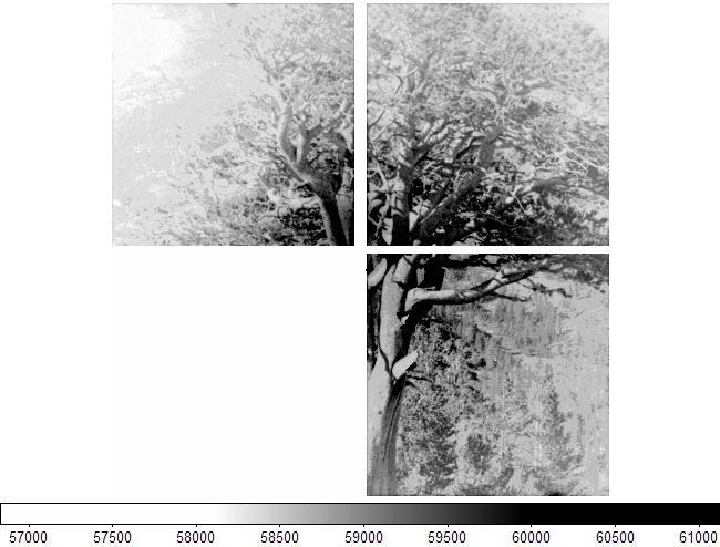
6 LBNL CCDs P-channel CCDs require opposite polarity bias voltages + Higher radiation tolerance Fully depleted CCDs require a depletion voltage + Less than 5µm rms point spread function Thick CCDs (~200µm) need to be over-depleted to achieve low charge diffusion P-channel 200 µm n+ ohmic contact C.J. Bebek et al "Development of Fully Depleted, Back- Illuminated Charge Coupled Devices," SPIE 5499, 10 (2004)
7 Analog signal processing design goals Low average power (~ 10 mw/channel ) - Will be higher during read-out Ultra low noise (< khz, equiv. 2 e- ) Large dynamic range (~96 db) On-chip A/D converter Good flexibility through programmable timing Radiation tolerance Operation cryogenically and at room temperature 10 mk temperature measurement resolution

8 Signal processing: the CRIC (CCD readout IC) 4 channels Pre-amplifier Single-ended to differential conversion Dual-slope integrator with three stage auto gain selection 14-bit pipeline ADC 25 µm CMOS implementation of CRIC Single Convert signal, all timing generated internally Test pulse injection for end-to end data flow test Voltage reference with warm and cryogenic mode
9 Signal Path Vref Input preamp Vref single to diff CDS multi slope int C 15 C 14-Bit Pipeline A/D Data Out 16 C
10 Signal Path Vref Input preamp Vref single to diff CDS multi slope int Pre-Amplifier C 15 C 16 C 14-Bit Pipeline A/D Data Out
11 Signal Path Vref Input Pre-Amplifier CDS preamp Vref single to diff CDS multi slope int C 15 C 14-Bit Pipeline A/D Data Out 16 C
12 Signal Path Vref Input preamp Pre-Amplifier CDS Voltage Reference Vref single to diff CDS multi slope int C 15 C 16 C 14-Bit Pipeline A/D Data Out
13 Signal Path Vref Input preamp Vref Pre-Amplifier CDS Voltage Reference Auto Gain Multi Slope single to diff CDS multi slope int C 15 C 16 C 14-Bit Pipeline A/D Data Out
14 Signal Path Vref Input preamp Vref Pre-Amplifier CDS Voltage Reference Auto Gain Multi Slope Pipeline ADC single to diff CDS multi slope int C 15 C 16 C 14-Bit Pipeline A/D Data Out
15 CRIC temperature V dd I ref2 I ref1 Dual slope ADC TPReset TPIref2 C~50pF TPSel TPPhi1 R~500k Vin Vs G~10 - Discriminator Vout - R T2 R T1 TPPhi2 + + V dd I ref R Ref R Off Vref Voff X1 To 11-bit counter
16 Switched current mirrors Test pulse injection Slope 1, 16,32 Vdd BandGap 1.65V Ch#2 Ch#3 Value (4-bit) 1.65V Gnd Ch#4 Straight Vdd Vref(1.65V) ch#1 Value: = 1.65V when Straight is high = 1.65V + ΔV when Straight is low Cal switch (Straight)
17 Noise 1500 Gain Gain ADC count Noise measured at the operating temperature of 140K: For small signals (high gain) noise is pre-amp dominated at 3.2 counts RMS, equivalent to 6.2 µv For larger signals (low gain) noise is ADC dominated at 1.5 counts RMS Gain
18 Integral Nonlinearity 0.8 Counts RMS INL 6.1 Counts pk-pk 1 Count = 1.93 µv
19 Power consumption Digital power 5.0 mw/channel in standby 5.8 mw/channel sampling at 100 khz Analog Power 0.25 mw/channel in standby 13.1 mw/channel sampling at 100 khz Standby is a low power mode where the bias currents to all amplifiers are disabled, but temperature monitoring and command interface remain active.

20 CLIC bias and clock generator Flexible clock pattern generator Clock level adjustments Programmable clock rise time Adjustable CCD bias voltage with controlled ramp rate 3.3 V generators for CRIC 12 adjustable bias voltages Supports radiation damage monitoring readout modes of CCD pocket pump, EPER, FPER.

21 CLIC bias and clock generator Vog Generators Serial Clock Driver SW RG pos Parallel Clock Driver a Digital Logic 6 bit DACs Serial Clock Driver Ha Hb CRIC 3.3V Generators Serial Clock Driver SW RG neg Vog Generators Vr Generator (M15 VDD Generator (M2 VSub Parallel Clock Driver b
22 Clock driver: principles of operation External storage capacitors
23 When the programmable discriminator senses a low output voltage the current source and output transistor are enabled to recharge the external capacitor which provides the rail for the clock drivers Clock driver details
24 Details continued The clock driver is powered during transitions only. (S1, S3) The programmable current mirror provides a linear voltage ramp. During the high phase the low-side drive transistor is turned off, and vice versa. (S2, S4) The gate capacitance of the output transistor maintains the On state after the transition
25 CLIC clocks (300 K) Cload = 150pF X 3 Cload = 60nF X 3 Parallel clock sequence Serial clock sequence 9.00 Positive voltage palteau vs DAC code 0 Negative voltage plateau vs DAC code h1 h2 h h1 h2 h
26 Bias DAC linearity Offset dispersion is understood and will be corrected Linearity is acceptable (~0.5 LSB INL)
27 Power consumption One of the main goals of the CLIC development is to minimize power consumption. The previous, fully tested version is the proof of principle incorporating all necessary functionality. 450 mw during normal CCD read-out. Many voltages can be disabled during exposure, greatly reducing average power. Optimization of the digital clock tree will dramatically reduce digital power. (~ ¼) Implementation of a band-gap reference instead of zener diodes for all voltage DACs is one of several measures taken to further reduce power in the next version.

28 Noise issues The main draw back of the previous version of the CLIC chip is a high noise level on the DC bias lines. This is due to a large excess noise component on the poly-2 resistors used for many feedback elements. The noise was not properly modeled in the design kit available at the time of chip submission, but has since been rectified. The choice of an implant resistor for the feed back will dramatically reduce noise.
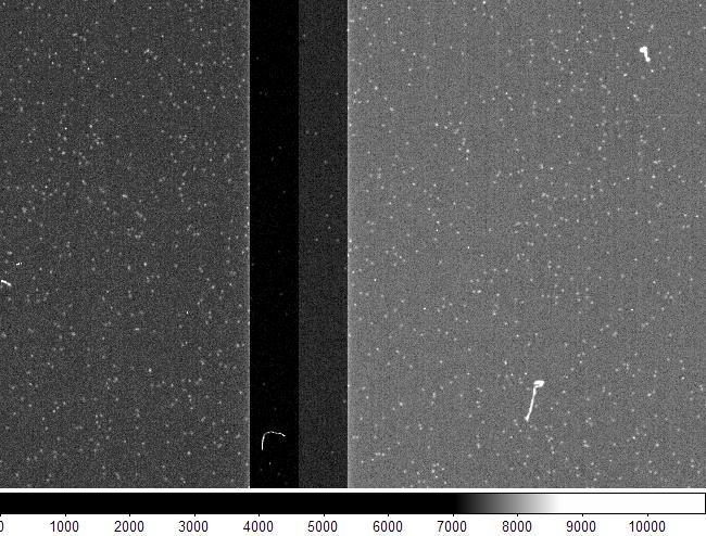
29 Radiation tolerance All flip-flops in CRIC and CLIC have been designed as 'DICE' SEU resistant storage elements. No latch-up has been observed in heavy ion testing to LET of 100 MeV/g cm 2. Observed SEU rates of 10-6 upsets/(particle/cm 2 ) are most likely due to radiation induced glitches on the asynchronous reset lines (hardened in next version). The current SEU rate translates to less than one upset per chip in ten years in L2 orbit without shielding.

30 System proof of principle
31 Conclusion We have designed a CCD readout system comprised of two ASICS. Preliminary testing of the new version of the clock driver is currently underway. Results are inconclusive, due to fabrication issues at the foundry potentially impacting yield. This version of the Clock driver and bias generator is expected to enable a very compact, low noise (2e - ) low power (~40 mw/channel average) readout system.
 Proof-of principle")
32 Outlook Higher speed More channels 16 Channel 1MHz readout IC (FCRIC) Proof-of principle exists
A rad-hard 8-channel 12-bit resolution ADC for slow control applications in the LHC environment
 A rad-hard 8-channel 12-bit resolution ADC for slow control applications in the LHC environment G. Magazzù 1,A.Marchioro 2,P.Moreira 2 1 INFN-PISA, Via Livornese 1291 56018 S.Piero a Grado (Pisa), Italy
A-D and D-A Converters
 Chapter 5 A-D and D-A Converters (No mathematical derivations) 04 Hours 08 Marks When digital devices are to be interfaced with analog devices (or vice a versa), Digital to Analog converter and Analog
Assoc. Prof. Dr. Burak Kelleci
 DEPARTMENT OF ELECTRICAL &ELECTRONICS ENGINEERING ANALOG-TO-DIGITAL AND DIGITAL- TO-ANALOG CONVERTERS Assoc. Prof. Dr. Burak Kelleci Fall 2018 OUTLINE Nyquist-Rate DAC Thermometer-Code Converter Hybrid
12-Bit, Low-Power, Dual, Voltage-Output DAC with Serial Interface
 19-2124; Rev 2; 7/3 12-Bit, Low-Power, Dual, Voltage-Output General Description The dual,12-bit, low-power, buffered voltageoutput, digital-to-analog converter (DAC) is packaged in a space-saving 8-pin
Comparison between Analog and Digital Current To PWM Converter for Optical Readout Systems
 Comparison between Analog and Digital Current To PWM Converter for Optical Readout Systems 1 Eun-Jung Yoon, 2 Kangyeob Park, 3* Won-Seok Oh 1, 2, 3 SoC Platform Research Center, Korea Electronics Technology
SCLK 4 CS 1. Maxim Integrated Products 1
 19-172; Rev ; 4/ Dual, 8-Bit, Voltage-Output General Description The contains two 8-bit, buffered, voltage-output digital-to-analog converters (DAC A and DAC B) in a small 8-pin SOT23 package. Both DAC
INL PLOT REFIN DAC AMPLIFIER DAC REGISTER INPUT CONTROL LOGIC, REGISTERS AND LATCHES
 ICm ictm IC MICROSYSTEMS FEATURES 12-Bit 1.2v Low Power Single DAC With Serial Interface and Voltage Output DNL PLOT 12-Bit 1.2v Single DAC in 8 Lead TSSOP Package Ultra-Low Power Consumption Guaranteed
INTEGRATED CIRCUITS. AN109 Microprocessor-compatible DACs Dec
 INTEGRATED CIRCUITS 1988 Dec DAC products are designed to convert a digital code to an analog signal. Since a common source of digital signals is the data bus of a microprocessor, DAC circuits that are
10-Bit, Low-Power, Rail-to-Rail Voltage-Output Serial DAC in SOT23
 19-195; Rev 1; 1/4 1-Bit, Low-Power, Rail-to-Rail General Description The is a small footprint, low-power, 1-bit digital-to-analog converter (DAC) that operates from a single +.7V to +5.5V supply. The
+2.7V to +5.5V, Low-Power, Triple, Parallel 8-Bit DAC with Rail-to-Rail Voltage Outputs
 19-1560; Rev 1; 7/05 +2.7V to +5.5V, Low-Power, Triple, Parallel General Description The parallel-input, voltage-output, triple 8-bit digital-to-analog converter (DAC) operates from a single +2.7V to +5.5V
Complete 14-Bit CCD/CIS Signal Processor AD9814
 a FEATURES 14-Bit 10 MSPS A/D Converter No Missing Codes Guaranteed 3-Channel Operation Up to 10 MSPS 1-Channel Operation Up to 7 MSPS Correlated Double Sampling 1-6x Programmable Gain 300 mv Programmable
A Prototype Amplifier-Discriminator Chip for the GLAST Silicon-Strip Tracker
 A Prototype Amplifier-Discriminator Chip for the GLAST Silicon-Strip Tracker Robert P. Johnson Pavel Poplevin Hartmut Sadrozinski Ned Spencer Santa Cruz Institute for Particle Physics The GLAST Project
1 A1 PROs. Ver0.1 Ai9943. Complete 10-bit, 25MHz CCD Signal Processor. Features. General Description. Applications. Functional Block Diagram
 1 A1 PROs A1 PROs Ver0.1 Ai9943 Complete 10-bit, 25MHz CCD Signal Processor General Description The Ai9943 is a complete analog signal processor for CCD applications. It features a 25 MHz single-channel
Complete 14-Bit CCD/CIS Signal Processor AD9822
 a FEATURES 14-Bit 15 MSPS A/D Converter No Missing Codes Guaranteed 3-Channel Operation Up to 15 MSPS 1-Channel Operation Up to 12.5 MSPS Correlated Double Sampling 1 6x Programmable Gain 350 mv Programmable
Status of Front End Development
 Status of Front End Development Progress of CSA and ADC studies Tim Armbruster tim.armbruster@ziti.uni-heidelberg.de CBM-XYTER Family Planning Workshop Schaltungstechnik und 05.12.2008 Introduction Previous
+2.7V to +5.5V, Low-Power, Dual, Parallel 8-Bit DAC with Rail-to-Rail Voltage Outputs
 9-565; Rev ; /99 +.7 to +5.5, Low-Power, Dual, Parallel General Description The MAX5 parallel-input, voltage-output, dual 8-bit digital-to-analog converter (DAC) operates from a single +.7 to +5.5 supply
ADC Bit µp Compatible A/D Converter
 ADC1001 10-Bit µp Compatible A/D Converter General Description The ADC1001 is a CMOS, 10-bit successive approximation A/D converter. The 20-pin ADC1001 is pin compatible with the ADC0801 8-bit A/D family.
Chapter 3 Novel Digital-to-Analog Converter with Gamma Correction for On-Panel Data Driver
 Chapter 3 Novel Digital-to-Analog Converter with Gamma Correction for On-Panel Data Driver 3.1 INTRODUCTION As last chapter description, we know that there is a nonlinearity relationship between luminance
Dual 256-Tap, Volatile, Low-Voltage Linear Taper Digital Potentiometers
 EVALUATION KIT AVAILABLE MAX5391/MAX5393 General Description The MAX5391/MAX5393 dual 256-tap, volatile, lowvoltage linear taper digital potentiometers offer three end-to-end resistance values of 1kΩ,
ISSN:
 1391 DESIGN OF 9 BIT SAR ADC USING HIGH SPEED AND HIGH RESOLUTION OPEN LOOP CMOS COMPARATOR IN 180NM TECHNOLOGY WITH R-2R DAC TOPOLOGY AKHIL A 1, SUNIL JACOB 2 1 M.Tech Student, 2 Associate Professor,
Differential Amplifiers
 Differential Amplifiers Benefits of Differential Signal Processing The Benefits Become Apparent when Trying to get the Most Speed and/or Resolution out of a Design Avoid Grounding/Return Noise Problems
Electronics A/D and D/A converters
 Electronics A/D and D/A converters Prof. Márta Rencz, Gábor Takács, Dr. György Bognár, Dr. Péter G. Szabó BME DED December 1, 2014 1 / 26 Introduction The world is analog, signal processing nowadays is
MCP Bit, Quad Digital-to-Analog Converter with EEPROM Memory. Features. Description. Applications
 12-Bit, Quad Digital-to-Analog Converter with EEPROM Memory Features 12-Bit Voltage Output DAC with Four Buffered Outputs On-Board Nonvolatile Memory (EEPROM) for DAC Codes and I 2 C Address Bits Internal
Linear Integrated Circuits
 Linear Integrated Circuits Single Slope ADC Comparator checks input voltage with integrated reference voltage, V REF At the same time the number of clock cycles is being counted. When the integrator output
Complete 16-Bit Imaging Signal Processor AD9826
 a FEATURES 16-Bit 15 MSPS A/D Converter 3-Channel 16-Bit Operation up to 15 MSPS 1-Channel 16-Bit Operation up to 12.5 MSPS 2-Channel Mode for Mono Sensors with Odd/Even Outputs Correlated Double Sampling
Dedan Kimathi University of technology. Department of Electrical and Electronic Engineering. EEE2406: Instrumentation. Lab 2
 Dedan Kimathi University of technology Department of Electrical and Electronic Engineering EEE2406: Instrumentation Lab 2 Title: Analogue to Digital Conversion October 2, 2015 1 Analogue to Digital Conversion
Ultra Low Power, High resolution ADC for Biomedical Applications
 Ultra Low Power, High resolution ADC for Biomedical Applications L. Hiremath, V. Mallapur, A. Stojcevski, J. Singh, H.P. Le, A. Zayegh Faculty of Science Engineering & Technology Victoria University, P.O.BOX
Front-End electronics developments for CALICE W-Si calorimeter
 Front-End electronics developments for CALICE W-Si calorimeter J. Fleury, C. de La Taille, G. Martin-Chassard G. Bohner, J. Lecoq, S. Manen IN2P3/LAL Orsay & LPC Clermont http::/www.lal.in2p3.fr/technique/se/flc
Quad 12-Bit Digital-to-Analog Converter (Serial Interface)
") Quad 1-Bit Digital-to-Analog Converter (Serial Interface) FEATURES COMPLETE QUAD DAC INCLUDES INTERNAL REFERENCES AND OUTPUT AMPLIFIERS GUARANTEED SPECIFICATIONS OVER TEMPERATURE GUARANTEED MONOTONIC OVER
Quad 1-Bit Digital-to-Analog Converter (Serial Interface) FEATURES COMPLETE QUAD DAC INCLUDES INTERNAL REFERENCES AND OUTPUT AMPLIFIERS GUARANTEED SPECIFICATIONS OVER TEMPERATURE GUARANTEED MONOTONIC OVER
A 14-bit 2.5 GS/s DAC based on Multi-Clock Synchronization. Hegang Hou*, Zongmin Wang, Ying Kong, Xinmang Peng, Haitao Guan, Jinhao Wang, Yan Ren
 Joint International Mechanical, Electronic and Information Technology Conference (JIMET 2015) A 14-bit 2.5 GS/s based on Multi-Clock Synchronization Hegang Hou*, Zongmin Wang, Ying Kong, Xinmang Peng,
All-digital ramp waveform generator for two-step single-slope ADC
 All-digital ramp waveform generator for two-step single-slope ADC Tetsuya Iizuka a) and Kunihiro Asada VLSI Design and Education Center (VDEC), University of Tokyo 2-11-16 Yayoi, Bunkyo-ku, Tokyo 113-0032,
12-Bit Successive-Approximation Integrated Circuit A/D Converter AD ADC80
 a 2-Bit Successive-Approximation Integrated Circuit A/D Converter FEATURES True 2-Bit Operation: Max Nonlinearity.2% Low Gain T.C.: 3 ppm/ C Max Low Power: 8 mw Fast Conversion Time: 25 s Precision 6.3
Advanced Regulating Pulse Width Modulators
 Advanced Regulating Pulse Width Modulators FEATURES Complete PWM Power Control Circuitry Uncommitted Outputs for Single-ended or Push-pull Applications Low Standby Current 8mA Typical Interchangeable with
ML4818 Phase Modulation/Soft Switching Controller
 Phase Modulation/Soft Switching Controller www.fairchildsemi.com Features Full bridge phase modulation zero voltage switching circuit with programmable ZV transition times Constant frequency operation
MIC38C42A/43A/44A/45A
 MIC38C42A/43A/44A/45A BiCMOS Current-Mode PWM Controllers General Description The MIC38C4xA are fixed frequency, high performance, current-mode PWM controllers. Micrel s BiCMOS devices are pin compatible
Low-Power, 12-Bit, Rail to Rail Voltage-Output Serial DAC in SOT23
 General Description The MAX5712 is a small footprint, low-power, 12-bit digitalto-analog converter (DAC) that operates from a single +2.7V to +5.5V supply. The MAX5712 on-chip precision output amplifier
Low-Power, Low-Glitch, Octal 12-Bit Voltage- Output DACs with Serial Interface
 9-232; Rev 0; 8/0 Low-Power, Low-Glitch, Octal 2-Bit Voltage- Output s with Serial Interface General Description The are 2-bit, eight channel, lowpower, voltage-output, digital-to-analog converters (s)
12-Bit Successive-Approximation Integrated Circuit ADC ADADC80
 2-Bit Successive-Approximation Integrated Circuit ADC FEATURES True 2-bit operation: maximum nonlinearity ±.2% Low gain temperature coefficient (TC): ±3 ppm/ C maximum Low power: 8 mw Fast conversion time:
9240LP LPTVREF. Memory DESCRIPTION: FEATURES: 14-Bit, 10 MSPS Monolithic A/D Converter with LPT ASIC. 9240LP Block Diagram 9240LP
 14-Bit, 10 MSPS Monolithic A/D Converter with LPT ASIC NC BIAS CAPB CAPT NC CML LPTref VinA VinB LPTAVDD LPTDVDD REFCOM Vref SENSE NC AVSS AVDD NC NC OTC BIT 1 BIT 2 BIT 3 BIT 4 BIT BIT 6 BIT 7 BIT 8 BIT
Features. 5V Reference UVLO. Oscillator S R GND*(AGND) 5 (9) ISNS 3 (5)
 5 (9) ISNS 3 (5)") MIC38HC42/3/4/5 BiCMOS 1A Current-Mode PWM Controllers General Description The MIC38HC4x family are fixed frequency current-mode PWM controllers with 1A drive current capability. Micrel s BiCMOS devices
MIC38HC42/3/4/5 BiCMOS 1A Current-Mode PWM Controllers General Description The MIC38HC4x family are fixed frequency current-mode PWM controllers with 1A drive current capability. Micrel s BiCMOS devices
MT1531 Series. CMOS, Programmable Linear Hall Effect Sensor. Features. Applications. 1 / 15
 Features Specified Operating Voltage Range Single supply voltage 4.5-5.5V Functions up to 7.0V Specified Operating Temperature Range From 40C up to 150C Linear Output with High Accuracy 12-bit Ratiometric
Low-Power Pipelined ADC Design for Wireless LANs
 Low-Power Pipelined ADC Design for Wireless LANs J. Arias, D. Bisbal, J. San Pablo, L. Quintanilla, L. Enriquez, J. Vicente, J. Barbolla Dept. de Electricidad y Electrónica, E.T.S.I. de Telecomunicación,
ECEN689: Special Topics in High-Speed Links Circuits and Systems Spring 2012
 ECEN689: Special Topics in High-Speed Links Circuits and Systems Spring 2012 Lecture 5: Termination, TX Driver, & Multiplexer Circuits Sam Palermo Analog & Mixed-Signal Center Texas A&M University Announcements
New Current-Sense Amplifiers Aid Measurement and Control
 AMPLIFIER AND COMPARATOR CIRCUITS BATTERY MANAGEMENT CIRCUIT PROTECTION Mar 13, 2000 New Current-Sense Amplifiers Aid Measurement and Control This application note details the use of high-side current
ADC Bit A/D Converter
 ADC0800 8-Bit A/D Converter General Description The ADC0800 is an 8-bit monolithic A/D converter using P-channel ion-implanted MOS technology. It contains a high input impedance comparator, 256 series
Multi-Channel Charge Pulse Amplification, Digitization and Processing ASIC for Detector Applications
 1.0 Multi-Channel Charge Pulse Amplification, Digitization and Processing ASIC for Detector Applications Peter Fischer for Tim Armbruster, Michael Krieger and Ivan Peric Heidelberg University Motivation
CCD Back Illuminated 2-Phase IMO Series Electron Multiplying CCD Sensor
 CCD201-20 Back Illuminated 2-Phase IMO Series Electron Multiplying CCD Sensor INTRODUCTION The CCD201 is a large format sensor (41k 2 ) in the L3Vision TM range of products from e2v technologies. This
Current Mode PWM Controller
 Current Mode PWM Controller UC1842/3/4/5 FEATURES Optimized For Off-line And DC To DC Converters Low Start Up Current (
Features. 5V Reference UVLO. Oscillator S R
 MIC38C42/3/4/5 BiCMOS Current-Mode PWM Controllers General Description The MIC38C4x are fixed frequency, high performance, current-mode PWM controllers. Micrel s BiCMOS devices are pin compatible with
Application Circuits 3. 3V R2. C4 100n G PI O. 0 G PI O S e t u p d a ta G PI O. 5 G PI O M o t i o n I n t G PI O. 4 G PI O.
 General Description The is an ultra-low power motion detector controller integrated circuit. The device is ideally suited for battery operated wireless motion sensors that make use of an MCU for handling
Nevis ADC Tes+ng. Tim Andeen. Columbia University. LAr ADC Review. June 4, LAr ADC Review. Tim Andeen
 Nevis ADC Tes+ng Columbia University June 4, 214 Outline v This talk - tesbng and performance IntroducBon Nevis 1 o performance and irradiabon Nevis 12 o performance and irradiabon First look at Nevis
LC2 MOS Octal 8-Bit DAC AD7228A
 a FEATURES Eight 8-Bit DACs with Output Amplifiers Operates with Single +5 V, +12 V or +15 V or Dual Supplies P Compatible (95 ns WR Pulse) No User Trims Required Skinny 24-Pin DlPs, SOIC, and 28-Terminal
10-Bit µp-compatible D/A converter
 DESCRIPTION The is a microprocessor-compatible monolithic 10-bit digital-to-analog converter subsystem. This device offers 10-bit resolution and ±0.1% accuracy and monotonicity guaranteed over full operating
Implementing a 5-bit Folding and Interpolating Analog to Digital Converter
 Implementing a 5-bit Folding and Interpolating Analog to Digital Converter Zachary A Pfeffer (pfefferz@colorado.edu) Department of Electrical and Computer Engineering University of Colorado, Boulder CO
Development of Radiation-Hard ASICs for the ATLAS Phase-1 Liquid Argon Calorimeter Readout Electronics Upgrade
 Development of Radiation-Hard ASICs for the ATLAS Phase-1 Liquid Argon Calorimeter Readout Electronics Upgrade Tim Andeen*, Jaroslav BAN, Nancy BISHOP, Gustaaf BROOIJMANS, Alex EMERMAN,Ines OCHOA, John
FAN MHz TinyBoost Regulator with 33V Integrated FET Switch
 FAN5336 1.5MHz TinyBoost Regulator with 33V Integrated FET Switch Features 1.5MHz Switching Frequency Low Noise Adjustable Output Voltage Up to 1.5A Peak Switch Current Low Shutdown Current:
Analog CMOS Interface Circuits for UMSI Chip of Environmental Monitoring Microsystem
 Analog CMOS Interface Circuits for UMSI Chip of Environmental Monitoring Microsystem A report Submitted to Canopus Systems Inc. Zuhail Sainudeen and Navid Yazdi Arizona State University July 2001 1. Overview
Supertex inc. HV892 HV892. Inductorless Liquid Lens Driver. General Description. Features. Applications. Typical Application Circuit. Supertex inc.
 Inductorless Liquid Lens Driver Features Drives capacitive loads up to 200pF Programmable drive amplitude (compatible with 40V RMS to 60V RMS lenses) On-chip boost converter No external inductor I 2 C
CHAPTER 8 PHOTOMULTIPLIER TUBE MODULES
 CHAPTER 8 PHOTOMULTIPLIER TUBE MODULES This chapter describes the structure, usage, and characteristics of photomultiplier tube () modules. These modules consist of a photomultiplier tube, a voltage-divider
A Low-Offset Latched Comparator Using Zero-Static Power Dynamic Offset Cancellation Technique
 1 A Low-Offset Latched Comparator Using Zero-Static Power Dynamic Offset Cancellation Technique Masaya Miyahara and Akira Matsuzawa Tokyo Institute of Technology, Japan 2 Outline Motivation Design Concept
Fast CMOS Transimpedance Amplifier and Comparator circuit for readout of silicon strip detectors at LHC experiments
 Fast CMOS Transimpedance Amplifier and Comparator circuit for readout of silicon strip detectors at LHC experiments Jan Kaplon - CERN Wladek Dabrowski - FPN/UMM Cracow Pepe Bernabeu IFIC Valencia Carlos
FUNCTIONAL BLOCK DIAGRAM DIGITAL VIDEO ENGINE
 FEATURES CMOS DUAL CHANNEL 10bit 40MHz DAC LOW POWER DISSIPATION: 180mW(+3V) DIFFERENTIAL NONLINEARITY ERROR: 0.5LSB SIGNAL-to-NOISE RATIO: 59dB SPURIOUS-FREE DYNAMIC RANGE:69dB BUILD-IN DIGITAL ENGINE
Lecture 6: Digital/Analog Techniques
 Lecture 6: Digital/Analog Techniques The electronics signals that we ve looked at so far have been analog that means the information is continuous. A voltage of 5.3V represents different information that
ALD500RAU/ALD500RA/ALD500R PRECISION INTEGRATING ANALOG PROCESSOR WITH PRECISION VOLTAGE REFERENCE
 ADVANCED LINEAR DEVICES, INC. ALD500RAU/ALD500RA/ALD500R PRECISION INTEGRATING ANALOG PROCESSOR WITH PRECISION VOLTAGE REFERENCE APPLICATIONS 4 1/2 digits to 5 1/2 digits plus sign measurements Precision
SPADIC Status and plans
 SPADIC Status and plans Michael Krieger TRD Strategy Meeting 29.11.2013 Michael Krieger SPADIC Status and plans 1 Reminder: SPADIC 1.0 architecture from detector pads single message stream: signal snapshot
CCD97 00 Front Illuminated 2-Phase IMO Series Electron Multiplying CCD Sensor
 CCD97 00 Front Illuminated 2-Phase IMO Series Electron Multiplying CCD Sensor INTRODUCTION The CCD97 is part of the new L3Vision 2 range of products from e2v technologies. This device uses a novel output
2.7 V to 5.5 V, 350 ksps, 10-Bit 4-/8-Channel Sampling ADCs AD7811/AD7812
 a FEATURES 10-Bit ADC with 2.3 s Conversion Time The AD7811 has Four Single-Ended Inputs that Can Be Configured as Three Pseudo Differential Inputs with Respect to a Common, or as Two Independent Pseudo
SF229 Low Power PIR Circuit IC For security applications
 Low Power PIR Circuit IC For security applications Preliminary datasheet DESCRIPTION The SF229 is a low power CMOS mixed signal ASIC designed for battery powered security applications that are either hard
Multiplexer for Capacitive sensors
 DATASHEET Multiplexer for Capacitive sensors Multiplexer for Capacitive Sensors page 1/7 Features Very well suited for multiple-capacitance measurement Low-cost CMOS Low output impedance Rail-to-rail digital
UNISONIC TECHNOLOGIES CO., LTD M1008 Preliminary CMOS IC
 UNISONIC TECHNOLOGIES CO, LTD M8 Preliminary CMOS IC 6-BIT CCD/CIS ANALOG SIGNAL PROCESSOR DESCRIPTION The M8 is a 6-bit CCD/CIS analog signal processor for imaging applications A 3-channel architecture
Analog I/O. ECE 153B Sensor & Peripheral Interface Design Winter 2016
 Analog I/O ECE 153B Sensor & Peripheral Interface Design Introduction Anytime we need to monitor or control analog signals with a digital system, we require analogto-digital (ADC) and digital-to-analog
A 130nm CMOS Evaluation Digitizer Chip for Silicon Strips readout at the ILC
 A 130nm CMOS Evaluation Digitizer Chip for Silicon Strips readout at the ILC Jean-Francois Genat Thanh Hung Pham on behalf of W. Da Silva 1, J. David 1, M. Dhellot 1, D. Fougeron 2, R. Hermel 2, J-F. Huppert
A 15.5 db, Wide Signal Swing, Dynamic Amplifier Using a Common- Mode Voltage Detection Technique
 A 15.5 db, Wide Signal Swing, Dynamic Amplifier Using a Common- Mode Voltage Detection Technique James Lin, Masaya Miyahara and Akira Matsuzawa Tokyo Institute of Technology, Japan Matsuzawa & Okada Laḃ
AD Bit, 20/40/65 MSPS 3 V Low Power A/D Converter. Preliminary Technical Data
 FEATURES Ultra Low Power 90mW @ 0MSPS; 135mW @ 40MSPS; 190mW @ 65MSPS SNR = 66.5 dbc (to Nyquist); SFDR = 8 dbc @.4MHz Analog Input ENOB = 10.5 bits DNL=± 0.5 LSB Differential Input with 500MHz Full Power
Tel: Fax:
 B Tel: 78.39.4700 Fax: 78.46.33 SPECIFICATIONS (T A = +5 C, V+ = +5 V, V = V or 5 V, all voltages measured with respect to digital common, unless otherwise noted) AD57J AD57K AD57S Model Min Typ Max Min
ANALOG TO DIGITAL (ADC) and DIGITAL TO ANALOG CONVERTERS (DAC)
 and DIGITAL TO ANALOG CONVERTERS (DAC)") COURSE / CODE DIGITAL SYSTEM FUNDAMENTALS (ECE421) DIGITAL ELECTRONICS FUNDAMENTAL (ECE422) ANALOG TO DIGITAL (ADC) and DIGITAL TO ANALOG CONVERTERS (DAC) Connecting digital circuitry to sensor devices
COURSE / CODE DIGITAL SYSTEM FUNDAMENTALS (ECE421) DIGITAL ELECTRONICS FUNDAMENTAL (ECE422) ANALOG TO DIGITAL (ADC) and DIGITAL TO ANALOG CONVERTERS (DAC) Connecting digital circuitry to sensor devices
Chapter 13: Introduction to Switched- Capacitor Circuits
 Chapter 13: Introduction to Switched- Capacitor Circuits 13.1 General Considerations 13.2 Sampling Switches 13.3 Switched-Capacitor Amplifiers 13.4 Switched-Capacitor Integrator 13.5 Switched-Capacitor
Analogue to Digital Conversion
 Analogue to Digital Conversion Turns electrical input (voltage/current) into numeric value Parameters and requirements Resolution the granularity of the digital values Integral NonLinearity proportionality
8-Bit A/D Converter AD673 REV. A FUNCTIONAL BLOCK DIAGRAM
 a FEATURES Complete 8-Bit A/D Converter with Reference, Clock and Comparator 30 s Maximum Conversion Time Full 8- or 16-Bit Microprocessor Bus Interface Unipolar and Bipolar Inputs No Missing Codes Over
16 V Rail-to-Rail, Zero-Drift, Precision Instrumentation Amplifier AD8230
 V Rail-to-Rail, Zero-Drift, Precision Instrumentation Amplifier AD FEATURES Resistor programmable gain range: to Supply voltage range: ± V to ± V, + V to + V Rail-to-rail input and output Maintains performance
LINEAR IC APPLICATIONS
 1 B.Tech III Year I Semester (R09) Regular & Supplementary Examinations December/January 2013/14 1 (a) Why is R e in an emitter-coupled differential amplifier replaced by a constant current source? (b)
9-Bit, 30 MSPS ADC AD9049 REV. 0. Figure 1. Typical Connections FUNCTIONAL BLOCK DIAGRAM
 a FEATURES Low Power: 00 mw On-Chip T/H, Reference Single +5 V Power Supply Operation Selectable 5 V or V Logic I/O Wide Dynamic Performance APPLICATIONS Digital Communications Professional Video Medical
A 4 GSample/s 8-bit ADC in. Ken Poulton, Robert Neff, Art Muto, Wei Liu, Andrew Burstein*, Mehrdad Heshami* Agilent Laboratories Palo Alto, California
 A 4 GSample/s 8-bit ADC in 0.35 µm CMOS Ken Poulton, Robert Neff, Art Muto, Wei Liu, Andrew Burstein*, Mehrdad Heshami* Agilent Laboratories Palo Alto, California 1 Outline Background Chip Architecture
High Speed System Applications
 High Speed System Applications 1. High Speed Data Conversion Overview 2. Optimizing Data Converter Interfaces 3. DACs, DDSs, PLLs, and Clock Distribution 4. PC Board Layout and Design Tools Copyright 2006
Volterra. VT1115MF Pulse Width Modulation (PWM) Controller. Partial Circuit Analysis
 Controller. Partial Circuit Analysis") Volterra VT1115MF Pulse Width Modulation (PWM) Controller Partial Circuit Analysis For questions, comments, or more information about this report, or for any additional technical needs concerning semiconductor
Volterra VT1115MF Pulse Width Modulation (PWM) Controller Partial Circuit Analysis For questions, comments, or more information about this report, or for any additional technical needs concerning semiconductor
4 x 10 bit Free Run A/D 4 x Hi Comparator 4 x Low Comparator IRQ on Compare MX839. C-BUS Interface & Control Logic
 DATA BULLETIN MX839 Digitally Controlled Analog I/O Processor PRELIMINARY INFORMATION Features x 4 input intelligent 10 bit A/D monitoring subsystem 4 High and 4 Low Comparators External IRQ Generator
Low Noise 300mA LDO Regulator General Description. Features
 Low Noise 300mA LDO Regulator General Description The id9301 is a 300mA with fixed output voltage options ranging from 1.5V, low dropout and low noise linear regulator with high ripple rejection ratio
+2.7 V to +5.5 V, Parallel Input, Voltage Output 8-Bit DAC AD7801
 a FEATURES Single 8-Bit DAC 2-Pin SOIC/TSSOP Package +2.7 V to +5.5 V Operation Internal and External Reference Capability DAC Power-Down Function Parallel Interface On-Chip Output Buffer Rail-to-Rail
10-Bit, 40 MSPS/60 MSPS A/D Converter AD9050 REV. B. Figure 1. Typical Connections FUNCTIONAL BLOCK DIAGRAM
 a FEATURES Low Power: 1 mw @ 0 MSPS, mw @ 0 MSPS On-Chip T/H, Reference Single + V Power Supply Operation Selectable V or V Logic I/O SNR: db Minimum at MHz w/0 MSPS APPLICATIONS Medical Imaging Instrumentation
HT82V Bit CCD/CIS Analog Signal Processor. Features. Applications. General Description. Block Diagram
 6-Bit CCD/CIS Analog Signal Processor Features Operating voltage: 33V Low power consumption at 56mW Power-down mode: Under A (clock timing keep low) 6-bit 6 MSPS A/D converter Guaranteed no missing codes
HT82V26A 16-Bit CCD/CIS Analog Signal Processor
 6-Bit CCD/CIS Analog Signal Processor Features Operating voltage: 5V Low power consumption at 4mW (Typ) Power-down mode: Under 2mA (Typ) 6-bit 3 MSPS A/D converter Guaranteed wont miss codes ~6 programmable
Short Channel Bandgap Voltage Reference
 Short Channel Bandgap Voltage Reference EE-584 Final Report Authors: Thymour Legba Yugu Yang Chris Magruder Steve Dominick Table of Contents Table of Figures... 3 Abstract... 4 Introduction... 5 Theory
Workshop ESSCIRC. Low-Power Data Acquisition System For Very Small Signals At Low Frequencies With12-Bit- SAR-ADC. 17. September 2010.
 Workshop ESSCIRC Low-Power Data Acquisition System For Very Small Signals At Low Frequencies With12-Bit- SAR-ADC 17. September 2010 Christof Dohmen Outline System Overview Analog-Front-End Chopper-Amplifier
Precision, Low-Power and Low-Noise Op Amp with RRIO
 MAX41 General Description The MAX41 is a low-power, zero-drift operational amplifier available in a space-saving, 6-bump, wafer-level package (WLP). Designed for use in portable consumer, medical, and
Universal Input Switchmode Controller
 Universal Input Switchmode Controller Si9120 FEATURES 10- to 0- Input Range Current-Mode Control 12-mA Output Drive Internal Start-Up Circuit Internal Oscillator (1 MHz) and DESCRIPTION The Si9120 is a
Microprocessor-compatible 8-Bit ADC. Memory FEATURES: Logic Diagram DESCRIPTION:
 7820 Microprocessor-compatible 8-Bit ADC FEATURES: 1.36 µs Conversion Time Built-in-Track-and-Hold Function Single +5 Volt Supply No External Clock Required Tri-State Output Buffered Total Ionization Dose:
PART TOP VIEW V EE 1 V CC 1 CONTROL LOGIC
 19-1331; Rev 1; 6/98 EVALUATION KIT AVAILABLE Upstream CATV Driver Amplifier General Description The MAX3532 is a programmable power amplifier for use in upstream cable applications. The device outputs
SPI-/I 2 C-Compatible, Temperature Sensor, 4-Channel ADC and Quad Voltage Output ADT7516/ADT7517/ADT7519
 SPI-/I 2 C-Compatible, Temperature Sensor, 4-Channel ADC and Quad Voltage Output ADT756/ADT757/ADT759 FEATURES ADT756: four 2-bit DACs ADT757: four -bit DACs ADT759: four 8-bit DACs Buffered voltage output
DUAL STEPPER MOTOR DRIVER
 DUAL STEPPER MOTOR DRIVER GENERAL DESCRIPTION The is a switch-mode (chopper), constant-current driver with two channels: one for each winding of a two-phase stepper motor. is equipped with a Disable input
Long Range Passive RF-ID Tag With UWB Transmitter
 Long Range Passive RF-ID Tag With UWB Transmitter Seunghyun Lee Seunghyun Oh Yonghyun Shim seansl@umich.edu austeban@umich.edu yhshim@umich.edu About RF-ID Tag What is a RF-ID Tag? An object for the identification