ADALAM Sensor based adaptive laser micromachining using ultrashort pulse lasers for zero-failure manufacturing
|
|
|
- Austen Dennis Dorsey
- 5 years ago
- Views:
Transcription
1 01/01/2015 Deliverable D2.3 Active alignment unit for beam coupling and sensor integration based on adaptive optics D2.3 Active alignment unit for beam coupling and sensor integration based on adaptive optics Document Coordinator: Contributors: Dissemination: Albert Borreman (Focal) DEMCON, Focal RESTRICTED Keywords: Adaptive optics, 5 DOF, Demonstrator 2.3, Date: 30/12/2015 Revision: UNIMETRIK
2 VERSION HISTORY VERSION DATE NOTES AND COMMENTS FIRST VERSION OF DOCUMENT CHANGES AFTER REVIEW UNIMETRIK CHANGES AFTER INTERNAL REVIEW FINAL FINAL EDITION Dissemination: PUBLIC 2/29
3 Table of content INTRODUCTION 4 WORK PACKAGE CONTEXT 4 Deliverable 2.3 context 5 BSU REQUIREMENTS 6 USE SCENARIOS 6 BSU CONCEPTS 7 CONCEPT 1A: DEFOCUS INTRODUCED BY DM 9 CONCEPT 3B: VOYAGER + ADDITIONAL 2-DOF STAGE 9 BSU DETAILED DESIGN 11 DETAILED DESIGN CONCEPT 1A 11 DETAILED DESIGN CONCEPT 5 DOF 12 BSU TEST AND ANALYSIS CONCEPT 1A 13 INPUT BEAM 13 MEASURE THE WAVEFRONT 14 CORRECT THE WAVEFRONT 16 DEFOCUS 16 ALIGNMENT 17 OVERLAPPING THE FOCI OF TWO BEAMS WITH DIFFERENT COLORS 19 CONCLUSIONS 23 BSU TEST AND ANALYSIS CONCEPT 3B 25 CONCLUSIONS 28 References Number Author(s) Description [1] Focal SRD for 5 DOF [2] Demcon CCD for 5 DOF [3] Focal SRD for BSU demonstrator [4] Focal CDD for BSU demosntrator [5] Lightmotif Task 3.1: Adaptive micromachining system conceptual design [6] OKO (Flexible Optical B.V.) OKO passport for mirror (passport_mmdm17tt.pdf) [7] OKO Breadboard adaptive optical system based on 19-channel MMDM: technical passport (AOS_manual.pdf) [8] OKO OKO Guide to Adaptive Optics [9] OKO FrontSurfer wavefront analysis and control system [10] Focal TAR for BSU demonstrator 11] Demcon TAR for 5 DOF Dissemination: PUBLIC 3/29

4 INTRODUCTION Work Package context The main objective of this work package is to design and implement a complete solution for an inline topography measurement and analysis for monitoring before, during and after the laser micro machining. The following approach integrates a high-resolution optical distance measurement system in the beam path of the laser micro machine, enabling an in-line measurement of the current state of the machined micro- and macro-structures directly in machine coordinates. Based on this device an automatic and adaptive process will be enabled. The following solution uses a low coherence spectral interferometer in a Michelson-type set-up, with a measurement path through the scanning optical system and an external reference path. Since the measurement wavelength and bandwidth cannot be the same as the milling laser, the overall optical aberrations of the measurement beam can be large. These aberrations will reduce the accuracy of the measurements systems and therefore these effect need to be characterized and compensated in the measurement system unit. The compensation is done by shaping the beam to ensure proper alignment (overlap) of the measurement beam to the milling beam and provide optimal measurement beam properties for OCT. The beamshaping unit (D.1) is part of the overall measurement system, see Figure 1. Figure 1 System architecture of measurement system Dissemination: PUBLIC 4/29
5 The beam shaping unit will rely heavily on the use of adaptive optical elements. An attractive feature of adaptive optics is that it can alleviate the extreme requirements on the scanning objective and can be tuned to the specific objective used in a setup after a calibration step. The objective of task 2.3 is to design and implement this type of beam shaping unit and couple the measurement beam into the milling laser optical path Deliverable 2.3 context Before the actual integration is done, first a beam shaping unit demonstrator is built. This document will present a summary of the development process and the final results of the demonstrator. The outcome of this deliverable will be used to realize a beam shaping unit that can be integrated in the micro milling machine of Lightmotif, WP3. The development follows the development protocol that is commonly used by Focal and DEMCON. 1. The first step is to define a set of requirements for the BSU. 2. The second step is about the investigation of the possible concepts that have the potential to meet the requirements. 3. The third step will be de detailed design of one or two of the concepts, resulting into drawings, specifications of components and a bill of materials. 4. The fourth step is the engineering phase in which the product is actually built and this phase ends with a test and analysis phase to verify whether the requirements have been met. In this document a short summary of each phase is presented with reference to the development documents that are used. System Requirements Document for the Beam Shaping and Coupling unit.[3] Concept design document for the beam shaping and coupling unit.[4] 5 DOF Adaptive subsystems for the beam shaping unit. [1] Concept and design document for 5 DoF adaptive subsystem. [2] Test and analysis report BSU demonstrator [10] Test and analysis report 5 DOF [11] Dissemination: PUBLIC 5/29
6 BSU REQUIREMENTS Use scenarios The main purpose of the BSU is to provide optimal measurement beam properties (diameter, quality, defocus, position, direction) for OCT such that the focus of the measurement beam coincides with the focus of the milling beam. The intended use is as follows: During the alignment procedure Lightmotif would like to be able to use a computer interface to properly align the measurement beam to the milling beam. Consequently this alignment is intended to be performed by means of actuated adaptive elements. For feedback, the beam measurement module and the measurement head will be used. Position, tip and tilt, and also defocus will have to be adjusted by means of a computer interface. In addition, if wavefront corrections are implemented, these will be determined during the alignment mode. A Shack-Hartmann sensor can be used to provide feedback for wavefront optimization. During measurement the beam shaping unit is static and remains in its determined optimal configuration [3]. This condition has the added benefit that the optical path length, an important parameter for OCT, remains constant Below the use scenario of the beam shaping unit is described by a description of the situation in use and the actions on the device by the involved users (Focal, Demcon, and eventually Lightmotif). It is foreseen that the beam shaping unit will be a module of the second generation OCT system on the Lightmotif machine. Figure 2: block scheme of the intended position of the BSU At interface i1 light will enter the beam shaping unit via a fiber. At interface i2 light will exit the beam shaping unit. This will be an open beam with certain properties in terms of diameter, defocus, and also wavefront aberrations, see technical requirements. The returning measurement beam follows the reverse path, see Figure 3. At interface i2 the returning beam will enter the beam shaping unit and at interface i1 the measurement beam will exit the beam shaping unit through the fiber. Figure 3: block scheme of the intended position of the BSU, reverse path Dissemination: PUBLIC 6/29
7 The functions of the BSU are listed in Table 1 Number Requirement Comments FR0101 Light from fiber to open beam with a diameter suitable for deformable mirror FR0102 Introduce defocus Tests needed. FR0104 FR0105 Provide optimal, fixed beam diameter for exit beam at i2 Position the sensing beam over the surrogate beam (x,y, tip, tilt) at the position of the intended scanner During alignment procedure, computer controlled actuation. FR0106 Couple the return beam into the beam splitter module Couple into fiber collimator. FR0107 Measure the beam wavefront During alignment procedure. FR0108 Correct the beam wavefront During alignment procedure. FR0109 Introduce only minimal OPL changes Corrections in reference path for instance by actuated or manual linear stage. Table 1 Main functions of BSU A detailed technical requirements list based on these functions can be found in [3]. In the second generation setup the position and angular alignment of the two beams has to be realized at the intended position of the scanner (back focal plane of the f-theta lens). This position is currently estimated to be at a distance of around or less than 1 m from the coupling mirror of the BSU. For the purpose of the demonstrator a distance of 1 m is considered. BSU CONCEPTS A modular breakdown of the required functions is described below. Where a choice with regards to the required equipment is already made, these choices will be mentioned. FR0106 and FR0109 relate to functions of the demonstrator which should be included as a result of its layout. Therefore they are not discussed here. Input beam (FR0101) implemented by means of a low-power monochrome laser module and a beam expander, see below. Using suitable components the required beam diameter should be attainable. The beam will be aligned to the optical axis of the beam expander by means of two mirrors mounted in Gimbal stages. In the images for the concept below, the input beam module will be included as a block labelled source. Defocus (FR0102) a number of options for introducing defocus will be described below. For all concepts the required and obtainable defocus range and resolution has to be verified (and if a defocus is needed). The obtainable defocus range (TR0103) and adjustment resolution (TR0104) will depend on the chosen concept and has to be tested. In the concepts described herein, FR0104, exit beam diameter at i2, is a resultant of the choices made. Dissemination: PUBLIC 7/29
8 Alignment (FR0105) for the alignment to the milling laser beam a combination of 2 tip/tilt mirrors (1 inch or 25 mm) will be applied to test this functionality. Schematically this setup will look as shown in Figure 4. In the image for the concept below, this module will be included as a block labelled alignment. The required range and resolution for the angular adjustment of the mirrors remains to be verified and the target values for the beam position have to be tested. If possible, the setup should be able to deliver specs according to TR0105, TR0106, TR0107, and TR0108. In the demonstrator, at interface i2 the beam could be combined with the surrogate beam by means of a beam splitter (not depicted in the images) to test the alignment capabilities. Figure 4: schematic illustration of the layout of the 2 tip/tilt mirrors for the alignment block. Wavefront measurement (FR0107) all wavefront measurements will be performed using a Shack-Hartmann (SH) sensor. In this case a ueye UI-3370CP-M-GL camera equipped with a micro lens array will be employed. A relay will be used to shrink the beam to fit the aperture of the SH sensor.this setup consists of 2 lenses (achromatic doublets, 100 mm and 150 mm). TR0112 and TR0113 will be determined using this equipment. Schematically this setup will look as shown in Figure 5. In the image for the concept below, this module will be included as a block labelled SH (with the beam splitter separately indicated, light green beam will be divided into two beams as well, not shown in Figure 5). It might be needed to place the SH sensor and the deformable mirror (DM) in optically conjugated planes. This could be realized in some of the concepts for this demonstrator by means of the placement of the relay. Figure 5: schematic illustration of the layout of the equipment for wavefront sensing. Wavefront correction (FR0108) for wavefront corrections an OKO membrane based deformable mirror with tip tilt (MMDM17TT) will be employed, see reference [6] for more Dissemination: PUBLIC 8/29
9 (technical) information on this device. TR0110 and TR0111 will be determined using this equipment. In the images for the concepts below, the deformable mirror will be included labelled DM. It should be noted that OKO describes that the quality of the adaptive optics corrections is defined by optical conjugation between the DM and the pupil of the system [8]. This could be tested in the demonstrator by placement of an additional afocal telescope of (preferably achromatic) refractive lenses between the pupil of the source and the DM (not depicted in the images). Several concepts have been considered and investigated [4]. The two most promising concepts will be presented in this document. Concept 1A: Defocus introduced by DM In this concept a defocus range is introduced by the deformable mirror. Doing so implies that wavefront correction and defocus are combined, since the deformable mirror will have to perform both functions. This combination is possibly to the detriment of the correction ranges, which has to be verified. In this concept an extra mirror is included in order to make it possible that the beam hits the DM under a small angle. A potential disadvantage of this concept is the following: A Micomachined Membrane Deformable Mirror (MMDM) has a biased operation in which the mirror surface is concave and acts as a lens. In this case, the optical power is around 0.5D. The biased shape might make this concept unsuitable. Particularly, in case only a small defocus range is allowed or required it might be needed to compensate for this optical power. If a (variable) lens based beam expander is used it might be possible to compensate for the bias by means of the collimation ring. This could be tested. Figure 6: schematic illustration of a concept in which defocus is introduced by a deformable mirror. Use of the mirror between source and DM is optional. Concept 3B: Voyager + additional 2-DOF stage This concept relies on the combination of Voyager and an additional 2-DOF stage to introduce defocus, similar to concept 3A. However, in this concept these two stages also provide the alignment function, see the Figure below. Therefore this concept can be realized by means of a reduced number of components compared to concept 3A. Wavefront measurement should be implemented after introduction of the defocus. Consequently in this concept the wavefront measurement should be implemented after the alignment unit, at interface i2. The SH sensor relies on an aligned beam for measurement. Due to this reason this concept has the disadvantage that wavefront measurement is not possible in the BSU and should be implemented elsewhere, for instance in the beam measurement unit of the second generation OCT setup. Dissemination: PUBLIC 9/29
10 Figure 7 schematic illustration of a concept in which defocus and alignment is introduced by Voyager and an additional 2-DOF tip/tilt stage (not depicted). Use of the mirror between source and DM is optional. The concept of the Voyager is shown in Figure 8, collimated light is delivered to the optical system. The desired output beam will pass through a desired position on the working area and optionally be convergent or divergent. In this case we aim for a beam which is either collimated or divergent (adjustable). Furthermore the axis of the resulting beam of light will be parallel to the incident beam on the mirror. To accomplish this result, the beam should be reflected with adjustable angles from mirror 1. In this fashion light can be directed onto mirror 2 such that given the correct (x,y,z) position and tip-tilt orientation of mirror 2, the desired output beam parameters will be achieved. To accomplish this output, mirror 1 which is placed in the 2-DOF subsystem should be able to tip and tilt (φ 1,ϴ 1). Mirror 2, in the 5-DOF subsystem, should be movable along the three axes of the system (Δx, Δy, Δz), and be able to tip and tilt (φ 2,ϴ 2). The adaptive subsystems will be controlled by electronics, not manually. Using feedback from sensors, the movements of the two mirrors will be monitored and controlled. Alternatively, suitable results could be achieved by means of calibration and a lookup table. In this concept the function to measure and correct the wavefront FR0107 and FR0108 is not implemented. The main component is this concept is the 5DOF stage. The requirements for this 5DOF stage are listed in Technical doc C [1]. It is not possible to find a commercially 5DOF stage that meets these requirements and therefore such a stage has been developed by DEMCON. Dissemination: PUBLIC 10/29

11 Figure 8 Schematic illustration (not to scale) of a simple concept relevant for ADALAM. Based on the specifications, a conceptual study about the 5DOF has been made by DEMCON, which is described in [2]. The chosen concept is a mirror mounted on a parallel flexure mechanism with six linear actuators. BSU DETAILED DESIGN Detailed Design Concept 1A The source for the demonstrator will be a 532 nm laser with a beam expander to adjust the size of the optical beam so that the beam diameter fits to the deformable mirror effective aperture of 15 mm. The deformable mirror will be a micromachined membrane deformable mirror that has 17 channels to deform the membrane and a tip tilt option that is based on piezo s. The beam-splitter will be a nonpolarizing cub splitter. The light path to the Shack Hartmann sensor requires a relay to fit the beam diameter to the Shack Hartmann sensor aperture. The alignment functionality will be done by using 2 motorized kinematic mounts with 25 mm coated mirrors. To test the performance a coupling to another laser beam will be done by using a beam splitter and the combined two beams will be monitored using two Positioning Sensor Detectors. This results into information about the position (error) and the divergence (error) of the measurement beam with respect to the test beam. After initial testing the concept was modified for the following two reasons: - it turns out that the collimation ring on the beam expander has insufficient range to correct for the bias shape of the deformable mirror. For this circumstance concept 1C has been defined. In this concept a lens is used to compensate the bias shape of the deformable mirror. - it was decided to use the relay telescope of the Shack-Hartmann sensor for the compensation of the bias of the deformable mirror. A collimated beam is achieved by displacing one of the constituent Dissemination: PUBLIC 11/29

12 lenses along the optical axis. Consequently, the lens in concept 1C is implemented as a set of 2 lenses. An advantage of this choice is that the diameter of the beam which goes into the alignment unit is more or less equal to the diameter of the beam which is probed by the Shack-Hartmann sensor. This beam diameter is suitable for the position sensors (PSD s) which are used to characterize the alignment function. The resulting implementation of the beam shaping and coupling unit is shown below. Figure 9: schematic illustration of the tested BSU demonstrator. In this concept defocus is introduced by a deformable mirror. The bias shape of the deformable mirror is compensated by the relay telescope of the Shack-Hartmann sensor. Therefore, in this figure the block SH depicts the Shack-Hartmann sensor without the relay telescope. The telescope is separately indicated. Detailed Design Concept 5 DOF To achieve accurate and fast motion, as specified, the system has four key design features: All heavy components mounted on a fixed and stiff frame Stiff connections to moving parts Lightweight moving components No friction and backlash Figure 10 shows the layout of the test setup as it has been designed, incorporating the mentioned key features. It consist of six linear actuators (voice coil motors) mounted on a base frame. To each motor a flexure linkage is connected. This linkage is stiff in longitudinal direction to be able to transfer the linear motion of the motor to the mirror mount. It does so without introducing friction or backlash. The mirror mount holds any optical component with a diameter of 1 inch (depicted here: parabolic mirror). Dissemination: PUBLIC 12/29


13 Figure 10: System layout respectively with frame visible and frame hidden BSU TEST AND ANALYSIS Concept 1A This chapter describes a summary of the obtained results. Detailed test results can be found in the Test and Analysis Report [10]. Input beam For the measurement beam light from a low-power monochromatic laser module is used. The beam is aligned to the optical axis of a variable beam expander by means of two mirrors mounted in Gimbals, see Figure 11. The variable beam expander expands the beam to the required diameter of 10 mm by means of setting the zoom and collimation options on the expander. Collimation of the beam was qualitatively verified by observing the beam diameter at several distances from the beam expander. The input beam was analysed, see the example in Figure 11. Figure 11 Left: image of the beam profile after the beam expander as recorded by a camera. The low power laser module is indicated with the arrow. Dissemination: PUBLIC 13/29

14 The beam diameter was determined by means of the horizontal and vertical cross-sections of these images. Analysis of Gaussian fits of these cross-sections indicates that the beam diameter is around 10.7 mm and 9.6 mm, for the horizontal and vertical directions respectively. Apparently the beam from this source is slightly elliptical with an average diameter of just over 10 mm. The obtained average beam diameter is within the range for optimal quality of correction by the deformable mirror. The continued beam path is as follows: the beam is directed to a mirror in a kinematic mount which reflects the beam to the deformable mirror. After being reflected by the deformable mirror the beam goes through the relay telescope, which reduces the beam diameter. Analysis of the Gaussian fits of the cross-sections of the imaged resulting beam profile indicates that the reduced beam diameter is around 7.4 mm and 6.5 mm, for the horizontal and vertical directions respectively. The average diameter is only slightly smaller than the clear aperture of the Shack-Hartmann sensor (< 9 mm). The beam is split by means of a 10:90 (R:T) non-polarizing beam splitter cube. The reflected beam is directed to the Shack-Hartmann sensor.the transmitted part of the beam goes to the alignment module. The Shack-Hartmann sensor and the deformable mirror are placed in conjugated planes. Measure the wavefront Wavefront measurements are performed using a Shack-Hartmann sensor and the OKO Frontsurfer software package [9]. The specified array focal distance is 18.6 mm, with an array pitch of 300 μm. The Shack-Hartmann sensor is used in absolute measurement mode. In the Figures below the measured wavefront of a beam with the deformable mirror in its bias state is shown. The used Shack-Hartmann sensor is shown in Figure 12. A more detailed photo is shown in Figure 14, including the relay, DMM and SH sensor. Figure 12: wavefront of the laser beam as obtained with the deformable mirror in the bias state. The software reports a Strehl ratio of The integration time of the Shack-Hartmann sensor was ms. Dissemination: PUBLIC 14/29
.")
.")

15 Figure 13Left: photograph of the used Shack-Hartmann sensor (arrow). Right: photograph of the deformable mirror. The aperture is on the left (arrow). Deformable mirror Relay Wavefront sensor Figure 14 Photograph of the breadboard setup of the demonstrator. Dissemination: PUBLIC 15/29

16 Correct the wavefront For wavefront corrections an OKO membrane based deformable mirror with tip tilt is employed, also in combination with the Frontsurfer software package. The deformable mirror allows the wavefront to be optimized by using feedback from the Shack-Hartmann sensor. This adaptive optics optimization entails a procedure in which the mirror is first calibrated. An initial requisite is that the laser beam is centred on the deformable mirror. If necessary the tip/tilt adjustments of the kinematic mirror mount in front of the deformable mirror can be used to align the beam to the centre of the deformable mirror. Note that the Shack-Hartmann sensor is placed after the beam splitter and in front of the alignment module. Therefore, in this demonstration setup, any aberrations introduced by the alignment unit or any other optics are uncorrected. Typical wavefronts as measured after optimization are shown in the Figures below: Figure 15 : measured wavefront of the laser beam as obtained after wavefront optimization. The software reports a Strehl ratio of The integration time of the Shack-Hartmann sensor was ms. The reported Strehl ratios are higher when compared to the starting conditions. Therefore the feedback procedure for optimization indeed results in improved wavefronts. Defocus Defocus: a defocused measurement beam might be required to obtain an overlap of the two beams focus spots. The above mentioned adaptive optics feedback procedure allows defocus to be introduced to the optimized beam by means of the deformable mirror. For this test it is investigated which optical powers can be achieved with the demonstrator. To do so the deformable mirror is first calibrated, followed by feedback optimization of the wavefront of the laser beam, and subsequent introduction of defocus. Defocus is introduced by manipulation of the corresponding Zernike coefficient C[2,0]. The value for this coefficient was increased until the operation range of the deformable mirror was exceeded. The initial starting condition is shown in Figure 12. In order to analyse the introduced defocus, the value reported for the measured optical power in Dioptres is plotted in the Figure below as a function of positive and negative defocus. Dissemination: PUBLIC 16/29
17 Optical Power (D) GA no: ,8 0,6 0,4 0, ,5-1 -0,5-0,2 0 0,5 1 1,5 2-0,4-0,6-0,8-1 C[2,0] (μm) Figure 16: measured optical power as a function of introduced defocus. The deformable mirror allows a range of optical powers to be introduced. In the demonstrator setup this range depends, amongst others, on the chosen relay telescope (offset) and the maximum deflections of the mirror elements. A wavefront with introduced defocus is shown in the Figure below. Figure 17: wavefront of the laser beam as obtained with defocus C[2,0] = -1.4 μm. The reported optical power is 0.565D. The integration time of the Shack-Hartmann sensor was ms. Alignment The alignment unit is implemented by means of a combination of 2 motorized tip/tilt mirrors, see the schematic Figure below. Dissemination: PUBLIC 17/29
. The distance between the two mirrors is around 26 cm. In the center two of the control cubes are visible.")

18 Figure 18 Top: schematic illustration of the alignment module. Two tip/tilt mirrors are used to accomplish the alignment. Bottom: photograph of the two motorized mirrors of the alignment module (blue arrows). The distance between the two mirrors is around 26 cm. In the center two of the control cubes are visible. The green arrows indicate the beam path To test the alignment unit, the equipment as shown below was used. The analysis setup uses two position sensors (PSD) to quantify the degree of alignment. PSD1 is placed close to the beam splitter, whereas PSD 2 is placed at a distance of around 1 meter from the beam splitter. Furthermore, the second mirror of the alignment unit is placed close to the beam splitter. Figure 19 schematic illustration of the test setup for the alignment unit. The green arrows depict the laser beam which models the measurement beam. In red the surrogate beam for the milling laser is depicted. In this case a 632 nm laser module is used. PSD1 is placed close to the beam splitter. PSD2 is placed at a distance of around 1 meter from the beamsplitter. Dissemination: PUBLIC 18/29
19 The specified resolution is 0.68 μm at maximum power level and 6.8 μm at 10% power. The recommended spot size is 0.2 to 7 mm. However, a maximum spot size of 9 mm is allowed. The software to control the motors and read-out the PSD s has been developed by ADALAM partner Demcon. The surrogate (milling) beam is a 632 nm laser module. To illustrate the functionality of this module, an example of the alignment results of the green beam to the red reference beam are presented below in a Tabular fashion. The typical time to alignment is below 1 minute and can get as low as a few seconds, depending on the quality of the pre-alignment. Furthermore, a short term stability measurement was performed. The resulting standard deviations are also included in the table. Start position red reference Position reported by PSD1 Position reported by PSD2 X1 (mm) Y1 (mm) X2 (mm) Y2 (mm) Start position green Aligned position green (difference) Short term stability, standard deviation (-0.008) (-0.003) (0.001) (0.001) Table 2: Overview of positions before and after alignment, as reported by the two PSD s. This test shows that alignment of the green laser beam to the reference beam was achieved with an accuracy of better than 10 micrometers at the two positions. Therefore the green beam was aligned to the red beam with an angular accuracy in the order of 20 μrads. Furthermore, the short term stability of the alignment was characterized by observing the position for a duration of around 1 minute. The observed resulting standard deviation for PSD2 is larger than the standard deviation for PSD1, which is probably due to the fact that PSD2 has a much longer optical path (1 meter from, versus close to the beam splitter). Overlapping the foci of two beams with different colors To test the functionality of the BSU a quick test was performed to overlap the foci of the two beams (red and green). After beam optimization and alignment a lens and camera are placed after the alignment unit, see Figure below. The lens is a 100 mm plano-convex and the spot is imaged by a camera. Dissemination: PUBLIC 19/29
, and camera. The used procedure is as follows.")
20 Figure 20 Left: schematic illustration of the setup used for testing the overlap of the focus of two beams. The green arrows depict the laser beam which models the measurement beam. In red the surrogate beam for the milling laser is depicted. Right: photograph of the used lens (arrow), and camera. The used procedure is as follows. Firstly, with the green beam blocked the camera is displaced such that the focus of the red laser is imaged on the camera, see Figure 14. The analysis of the spot diameter is performed by means of the OKO Beamtuner software. The reported beam diameter is 4.5 pixels. Figure 21: image from OKO Beamtuner of the focus of the red beam. The reported spot diameter is 4.5 pixels. Secondly, the red beam is blocked and the spot of the green beam is imaged, see Figure 15. Here, the beam quality was optimized to a flat wavefront, similar to Figures 7 and 8. It appears that the camera is out of focus (as expected) and that beam modification is necessary to obtain a focus which overlaps the position of the red spot. Dissemination: PUBLIC 20/29

. The reported spot diameter is 3.59 pixels.")
21 Figure 22: image from OKO Beamtuner of the focus of the green beam. The reported spot diameter is pixels. Thirdly, two methods can be applied to modify the beam such that overlap is achieved. The first method is by means of the OKO Beamtuner software, which offers a routine to optimize the deformable mirror settings such that a small spot is obtained at the desired position. The resulting situation is shown in Figure 16. Figure 23: image from OKO Beamtuner of the focus of the green beam as optimized to overlap the original position of the focus of the red beam (red cross). The reported spot diameter is 3.59 pixels. The second method is to use the feedback option in the Frontsurfer software to introduce a suitable defocus to the green beam. For this first test this was accomplished by manually optimizing the defocus setting to obtain the smallest spot, see Figure 17 for the resulting spot diameter. Dissemination: PUBLIC 21/29

22 Figure 24: image from OKO Beamtuner of the focus of the green beam as optimized to overlap the original position of the focus of the red beam (red cross). Optimization was performed by introducing a defocus of 0.78 μm to the beam. The reported spot diameter is 2.99 pixels. After optimization the wavefront was measured, see Figure 18. In this case a reasonably large defocus setting of 0.78 μm was required. Figure 25: wavefront of the laser beam as it was used to overlap the focus with the focus of the red beam in Figure 21. In this case a defocus setting of 0.78 μm was applied. These first tests indicate that it is indeed possible to overlap the foci of two beams with different colors by means of adjusting the defocus of the green beam. Both tested methods accomplish a qualitative overlap in the plane of the camera. The accuracy of the overlap of the two spots has not yet been quantified. Dissemination: PUBLIC 22/29


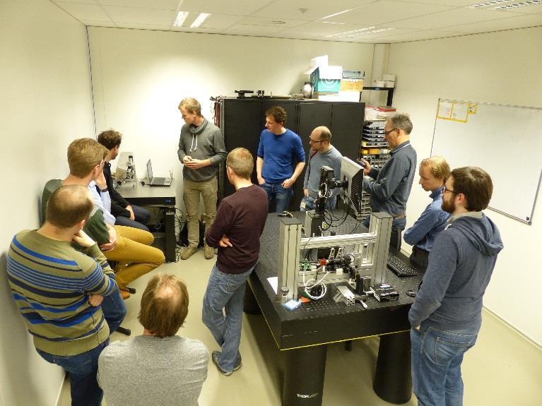
23 Conclusions The performed tests indicate that the BSU demonstrator performs the following functions: - A beam with a diameter of around 10 mm was obtained at the position of the deformable mirror - The deformable mirror can be used to introduce defocus to the laser beam - Alignment of the modelled measurement beam over the surrogate beam was demonstrated - The wavefront of the laser beam can be measured by means of the Shack-Hartmann sensor - The deformable mirror can be used for beam optimization - In an initial test the demonstrator was used to overlap the foci of two laser beams with different wavelengths and through the same lens. More tests will be performed to gain more insight in the accuracies and ranges of the various measurements and adjustments. The current status with regards to the technical requirements as listed in the SRD are shown below. A demonstrator session for Demcon, Lightmotif and Focal engineers was organised on the at the optical lab of Focal. Some photographs of this session are shown below. Dissemination: PUBLIC 23/29
24 Number Requirement Relation Value Status TR0101 Diameter of beam after fiber collimator = ~ 10 mm (1/e 2 ) Demonstrated with laser module and beam expander. To be adapted for fiber collimator. TR0102 Diameter of exit beam at i2 < 14 mm (1/e 2 ) Demonstrated. TR0103 Defocus range = INF to +/- 0.8D First test: INF to /- 0.75D TR0104 Defocus adjustment resolution = TBD Value can be determined with this setup. TR0105 Adjust beam position (x,y) range at i2 >= 5 mm (+/- 2.5 mm) Value can be determined with this setup. TR0106 Beam position adjustment resolution <= 1 μm Target value. Demonstrated value of around 10 μm. TR0107 Adjust beam angles (tip, tilt) range = +/- 1.4 mrad (reflected beam) TR0108 Beam angles adjustment resolution < 10 μrad [4] (reflected beam) TR0109 Adjustment rates (position, tip, tilt, defocus, aberration corrections) during alignment procedure Value can be determined with this setup. First test: Demonstrated value in the order of 20 μrad. = Around 1 Hz Demonstrated time to total alignment of below 1 minute. Total time can get as low as a few seconds. TR0110 Wavefront aberration correction range = TBD Value can be determined with this setup. TR0111 Wavefront aberration correction accuracy = TBD Value can be determined with this setup. TR0112 Wavefront measurement range = TBD Value can be determined with this setup. TR0113 Wavefront measurement accuracy = TBD Value can be determined with this setup. Dissemination: PUBLIC 24/29
 TR0115 All potentially hazardous laser beams are prevented from leaving the setup area by using suitable blocks/enclosures Not tested, but value is expected to be achieved.")

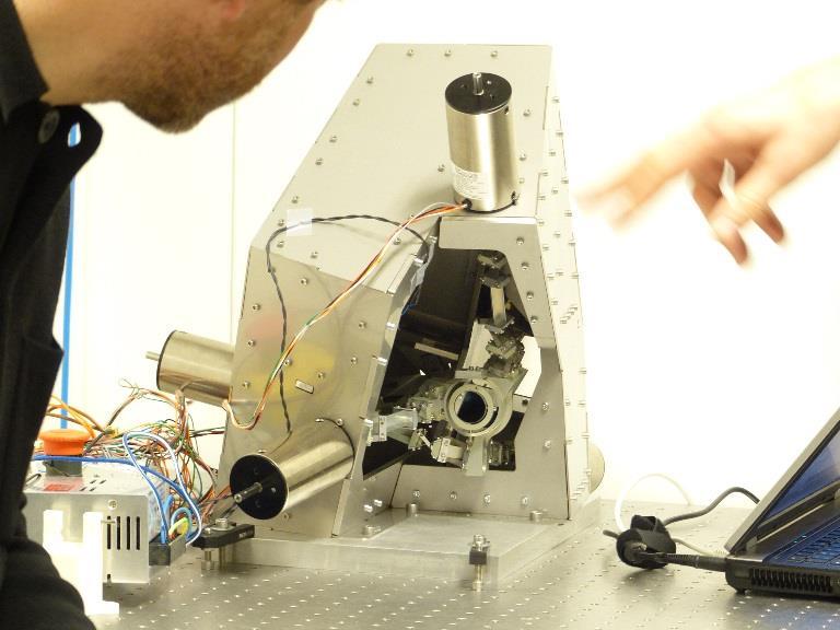
25 TR0114 Introduced maximum change of the OPL <= 25 mm (+/ mm) TR0115 All potentially hazardous laser beams are prevented from leaving the setup area by using suitable blocks/enclosures Not tested, but value is expected to be achieved. = TRUE Light sources pose risk for operator and bystanders; operator has to wear suitable safety goggles when indicated. BSU TEST AND ANALYSIS Concept 3B This chapter describes a summary of the obtained results of the 5DOF-stage. Detailed test results can be found in the Test and Analysis Report [11]. Figure 26: Actual system, side view and front view respectively Firstly eigenfrequencies of the system were measured by actuating each motor in turn with a random signal and measuring the response at the encoder of this motor. This was done on the frame only, on the complete assembly and on the assembly in a deflected state. Measurements were compared to FEM results, where the frame has been modeled in two ways: bodned edges and free edges. The results are shown in the table below. It can be concluded that the system conforms well to the model, the eigenfrequencies are within the expected range. Dissemination: PUBLIC 25/29
26 Actuated by and measured at # FEM result in case of bonded edges (Hz) FEM result in case of free edges (Hz) Case 1: Measured frequency of frame only, without mechanism (Hz) Case 2; Measured frequency assembled system, undeflected (Hz) Table 3: Calculated and measured eigenfrequencies Case 3: Measured frequency assembled system, deflected (Hz) Secondly, dynamic performance has been tested and compared to the simulations. The result of one of these tests is shown in the graph below. From this it can be concluded that the system lags more than expected behind the reference signal. The cause is an unanticipated high amount of friction in the voice coils. Figure 27: Simulated and measured dynamic performance Lastly, the repeatability of the system has been tested. This has been done by bouncing a laser off of a mirror mounted in the system and onto a PSD. The position of the spot is registered, after which the system undergoes some random motions. Afterwards, the system is sent back to the original position and the position of the laser spot is registered again. The difference between both registered spot Dissemination: PUBLIC 26/29

27 positions is a measure for the repeatability. The figure below shows the test set-up and the deviation of the second registered spots. Figure 28: Repeatability test-set up and results From the results the following repeatability s are calculated: x y z Rx Ry Rz Expected repeatability ±1,5 μm ±4,7 μm ±1,5 μm ±82 μrad ±98 μrad ±153 μrad Measured repeatability ±2 μm ±4 μm - ±35 μrad ±37 μrad - Table 4: Calculated repeatabilities Currently, the repeatabilities are not always within specification, but the main cause seems to be the motors and not the mechanism itself. The expectation is that a different set of motors (less friction, higher resolution encoders) will enable the system to achieve the specification. Dissemination: PUBLIC 27/29

28 Figure 29: Test setup Conclusions It has been demonstrated that the 5 DOF stage can be used to adjust tip, tilt, and the x,y,x movements with about 50Hz. It has been demonstrated that the repeatability is slightly off with respect to the expectations Further test are needed to show the principle of concept 3B. The 5DOF has been demonstrated at the demonstration session on Some pictures are shown below. Dissemination: PUBLIC 28/29
29 Dissemination: PUBLIC 29/29
Ron Liu OPTI521-Introductory Optomechanical Engineering December 7, 2009
 Synopsis of METHOD AND APPARATUS FOR IMPROVING VISION AND THE RESOLUTION OF RETINAL IMAGES by David R. Williams and Junzhong Liang from the US Patent Number: 5,777,719 issued in July 7, 1998 Ron Liu OPTI521-Introductory
ADALAM Sensor based adaptive laser micromachining using ultrashort pulse lasers for zero-failure manufacturing D2.2. Ger Folkersma (Demcon)
") D2.2 Automatic adjustable reference path system Document Coordinator: Contributors: Dissemination: Keywords: Ger Folkersma (Demcon) Ger Folkersma, Kevin Voss, Marvin Klein (Demcon) Public Reference path,
D2.2 Automatic adjustable reference path system Document Coordinator: Contributors: Dissemination: Keywords: Ger Folkersma (Demcon) Ger Folkersma, Kevin Voss, Marvin Klein (Demcon) Public Reference path,
Breadboard adaptive optical system based on 109-channel PDM: technical passport
 F L E X I B L E Flexible Optical B.V. Adaptive Optics Optical Microsystems Wavefront Sensors O P T I C A L Oleg Soloviev Chief Scientist Röntgenweg 1 2624 BD, Delft The Netherlands Tel: +31 15 285 15-47
CHARA AO Calibration Process
 CHARA AO Calibration Process Judit Sturmann CHARA AO Project Overview Phase I. Under way WFS on telescopes used as tip-tilt detector Phase II. Not yet funded WFS and large DM in place of M4 on telescopes
Proposed Adaptive Optics system for Vainu Bappu Telescope
 Proposed Adaptive Optics system for Vainu Bappu Telescope Essential requirements of an adaptive optics system Adaptive Optics is a real time wave front error measurement and correction system The essential
Supplementary Materials
 Supplementary Materials In the supplementary materials of this paper we discuss some practical consideration for alignment of optical components to help unexperienced users to achieve a high performance
Adaptive Optics for LIGO
 Adaptive Optics for LIGO Justin Mansell Ginzton Laboratory LIGO-G990022-39-M Motivation Wavefront Sensor Outline Characterization Enhancements Modeling Projections Adaptive Optics Results Effects of Thermal
Eric B. Burgh University of Wisconsin. 1. Scope
 Southern African Large Telescope Prime Focus Imaging Spectrograph Optical Integration and Testing Plan Document Number: SALT-3160BP0001 Revision 5.0 2007 July 3 Eric B. Burgh University of Wisconsin 1.
OPTICS IN MOTION. Introduction: Competing Technologies: 1 of 6 3/18/2012 6:27 PM.
 1 of 6 3/18/2012 6:27 PM OPTICS IN MOTION STANDARD AND CUSTOM FAST STEERING MIRRORS Home Products Contact Tutorial Navigate Our Site 1) Laser Beam Stabilization to design and build a custom 3.5 x 5 inch,
Aberrations and adaptive optics for biomedical microscopes
 Aberrations and adaptive optics for biomedical microscopes Martin Booth Department of Engineering Science And Centre for Neural Circuits and Behaviour University of Oxford Outline Rays, wave fronts and
Optical Components for Laser Applications. Günter Toesko - Laserseminar BLZ im Dezember
 Günter Toesko - Laserseminar BLZ im Dezember 2009 1 Aberrations An optical aberration is a distortion in the image formed by an optical system compared to the original. It can arise for a number of reasons
1.6 Beam Wander vs. Image Jitter
 8 Chapter 1 1.6 Beam Wander vs. Image Jitter It is common at this point to look at beam wander and image jitter and ask what differentiates them. Consider a cooperative optical communication system that
AgilOptics mirrors increase coupling efficiency into a 4 µm diameter fiber by 750%.
 Application Note AN004: Fiber Coupling Improvement Introduction AgilOptics mirrors increase coupling efficiency into a 4 µm diameter fiber by 750%. Industrial lasers used for cutting, welding, drilling,
WaveMaster IOL. Fast and Accurate Intraocular Lens Tester
 WaveMaster IOL Fast and Accurate Intraocular Lens Tester INTRAOCULAR LENS TESTER WaveMaster IOL Fast and accurate intraocular lens tester WaveMaster IOL is an instrument providing real time analysis of
Difrotec Product & Services. Ultra high accuracy interferometry & custom optical solutions
 Difrotec Product & Services Ultra high accuracy interferometry & custom optical solutions Content 1. Overview 2. Interferometer D7 3. Benefits 4. Measurements 5. Specifications 6. Applications 7. Cases
EE119 Introduction to Optical Engineering Fall 2009 Final Exam. Name:
 EE119 Introduction to Optical Engineering Fall 2009 Final Exam Name: SID: CLOSED BOOK. THREE 8 1/2 X 11 SHEETS OF NOTES, AND SCIENTIFIC POCKET CALCULATOR PERMITTED. TIME ALLOTTED: 180 MINUTES Fundamental
Open-loop performance of a high dynamic range reflective wavefront sensor
 Open-loop performance of a high dynamic range reflective wavefront sensor Jonathan R. Andrews 1, Scott W. Teare 2, Sergio R. Restaino 1, David Wick 3, Christopher C. Wilcox 1, Ty Martinez 1 Abstract: Sandia
WaveMaster IOL. Fast and accurate intraocular lens tester
 WaveMaster IOL Fast and accurate intraocular lens tester INTRAOCULAR LENS TESTER WaveMaster IOL Fast and accurate intraocular lens tester WaveMaster IOL is a new instrument providing real time analysis
Development of a Low-order Adaptive Optics System at Udaipur Solar Observatory
 J. Astrophys. Astr. (2008) 29, 353 357 Development of a Low-order Adaptive Optics System at Udaipur Solar Observatory A. R. Bayanna, B. Kumar, R. E. Louis, P. Venkatakrishnan & S. K. Mathew Udaipur Solar
MODULAR ADAPTIVE OPTICS TESTBED FOR THE NPOI
 MODULAR ADAPTIVE OPTICS TESTBED FOR THE NPOI Jonathan R. Andrews, Ty Martinez, Christopher C. Wilcox, Sergio R. Restaino Naval Research Laboratory, Remote Sensing Division, Code 7216, 4555 Overlook Ave
Solution of Exercises Lecture Optical design with Zemax Part 6
 2013-06-17 Prof. Herbert Gross Friedrich Schiller University Jena Institute of Applied Physics Albert-Einstein-Str 15 07745 Jena Solution of Exercises Lecture Optical design with Zemax Part 6 6 Illumination
Lecture 2: Geometrical Optics. Geometrical Approximation. Lenses. Mirrors. Optical Systems. Images and Pupils. Aberrations.
 Lecture 2: Geometrical Optics Outline 1 Geometrical Approximation 2 Lenses 3 Mirrors 4 Optical Systems 5 Images and Pupils 6 Aberrations Christoph U. Keller, Leiden Observatory, keller@strw.leidenuniv.nl
Optical Engineering 421/521 Sample Questions for Midterm 1
 Optical Engineering 421/521 Sample Questions for Midterm 1 Short answer 1.) Sketch a pechan prism. Name a possible application of this prism., write the mirror matrix for this prism (or any other common
Wavefront Sensing In Other Disciplines. 15 February 2003 Jerry Nelson, UCSC Wavefront Congress
 Wavefront Sensing In Other Disciplines 15 February 2003 Jerry Nelson, UCSC Wavefront Congress QuickTime and a Photo - JPEG decompressor are needed to see this picture. 15feb03 Nelson wavefront sensing
AgilEye Manual Version 2.0 February 28, 2007
 AgilEye Manual Version 2.0 February 28, 2007 1717 Louisiana NE Suite 202 Albuquerque, NM 87110 (505) 268-4742 support@agiloptics.com 2 (505) 268-4742 v. 2.0 February 07, 2007 3 Introduction AgilEye Wavefront
Miniaturisation, advanced highperformance
 SENSOR-BASED ADAPTIVE LASER MACHINING USING ULTRASHORT-PULSE LASERS WORK IN PROGRESS: SMART MICROMACHINING The European ADALAM project aims to develop a sensor-based adaptive micromachining system for
DETERMINING CALIBRATION PARAMETERS FOR A HARTMANN- SHACK WAVEFRONT SENSOR
 DETERMINING CALIBRATION PARAMETERS FOR A HARTMANN- SHACK WAVEFRONT SENSOR Felipe Tayer Amaral¹, Luciana P. Salles 2 and Davies William de Lima Monteiro 3,2 Graduate Program in Electrical Engineering -
Design Description Document
 UNIVERSITY OF ROCHESTER Design Description Document Flat Output Backlit Strobe Dare Bodington, Changchen Chen, Nick Cirucci Customer: Engineers: Advisor committee: Sydor Instruments Dare Bodington, Changchen
OPAL. SpotOptics. AUTOMATED WAVEFRONT SENSOR Single and double pass O P A L
 Spotptics The software people for optics UTMTED WVEFRNT SENSR Single and double pass ccurate metrology of standard and aspherical lenses ccurate metrology of spherical and flat mirrors =0.3 to =60 mm F/1
DIMENSIONAL MEASUREMENT OF MICRO LENS ARRAY WITH 3D PROFILOMETRY
 DIMENSIONAL MEASUREMENT OF MICRO LENS ARRAY WITH 3D PROFILOMETRY Prepared by Benjamin Mell 6 Morgan, Ste156, Irvine CA 92618 P: 949.461.9292 F: 949.461.9232 nanovea.com Today's standard for tomorrow's
ADVANCED OPTICS LAB -ECEN Basic Skills Lab
 ADVANCED OPTICS LAB -ECEN 5606 Basic Skills Lab Dr. Steve Cundiff and Edward McKenna, 1/15/04 Revised KW 1/15/06, 1/8/10 Revised CC and RZ 01/17/14 The goal of this lab is to provide you with practice
Lecture 4: Geometrical Optics 2. Optical Systems. Images and Pupils. Rays. Wavefronts. Aberrations. Outline
 Lecture 4: Geometrical Optics 2 Outline 1 Optical Systems 2 Images and Pupils 3 Rays 4 Wavefronts 5 Aberrations Christoph U. Keller, Leiden University, keller@strw.leidenuniv.nl Lecture 4: Geometrical
PROCEEDINGS OF SPIE. Measurement of low-order aberrations with an autostigmatic microscope
 PROCEEDINGS OF SPIE SPIEDigitalLibrary.org/conference-proceedings-of-spie Measurement of low-order aberrations with an autostigmatic microscope William P. Kuhn Measurement of low-order aberrations with
MALA MATEEN. 1. Abstract
 IMPROVING THE SENSITIVITY OF ASTRONOMICAL CURVATURE WAVEFRONT SENSOR USING DUAL-STROKE CURVATURE: A SYNOPSIS MALA MATEEN 1. Abstract Below I present a synopsis of the paper: Improving the Sensitivity of
3.0 Alignment Equipment and Diagnostic Tools:
 3.0 Alignment Equipment and Diagnostic Tools: Alignment equipment The alignment telescope and its use The laser autostigmatic cube (LACI) interferometer A pin -- and how to find the center of curvature
Paper Synopsis. Xiaoyin Zhu Nov 5, 2012 OPTI 521
 Paper Synopsis Xiaoyin Zhu Nov 5, 2012 OPTI 521 Paper: Active Optics and Wavefront Sensing at the Upgraded 6.5-meter MMT by T. E. Pickering, S. C. West, and D. G. Fabricant Abstract: This synopsis summarized
Payload Configuration, Integration and Testing of the Deformable Mirror Demonstration Mission (DeMi) CubeSat
 CubeSat") SSC18-VIII-05 Payload Configuration, Integration and Testing of the Deformable Mirror Demonstration Mission (DeMi) CubeSat Jennifer Gubner Wellesley College, Massachusetts Institute of Technology 21 Wellesley
SSC18-VIII-05 Payload Configuration, Integration and Testing of the Deformable Mirror Demonstration Mission (DeMi) CubeSat Jennifer Gubner Wellesley College, Massachusetts Institute of Technology 21 Wellesley
Laser Speckle Reducer LSR-3000 Series
 Datasheet: LSR-3000 Series Update: 06.08.2012 Copyright 2012 Optotune Laser Speckle Reducer LSR-3000 Series Speckle noise from a laser-based system is reduced by dynamically diffusing the laser beam. A
ADVANCED OPTICS LAB -ECEN 5606
 ADVANCED OPTICS LAB -ECEN 5606 Basic Skills Lab Dr. Steve Cundiff and Edward McKenna, 1/15/04 rev KW 1/15/06, 1/8/10 The goal of this lab is to provide you with practice of some of the basic skills needed
Week IX: INTERFEROMETER EXPERIMENTS
 Week IX: INTERFEROMETER EXPERIMENTS Notes on Adjusting the Michelson Interference Caution: Do not touch the mirrors or beam splitters they are front surface and difficult to clean without damaging them.
PHYS 3153 Methods of Experimental Physics II O2. Applications of Interferometry
 Purpose PHYS 3153 Methods of Experimental Physics II O2. Applications of Interferometry In this experiment, you will study the principles and applications of interferometry. Equipment and components PASCO
OPTINO. SpotOptics VERSATILE WAVEFRONT SENSOR O P T I N O
 Spotptics he software people for optics VERSALE WAVEFR SESR Accurate metrology in single and double pass Lenses, mirrors and laser beams Any focal length and diameter Large dynamic range Adaptable for
SpotOptics. The software people for optics OPAL O P A L
 Spotptics The software people for optics UTMTED WVEFRNT SENSR ccurate metrology of standard and aspherical lenses (single pass) ccurate metrology of spherical and flat mirrors (double pass) =0.3 to =50
ΘΘIntegrating closedloop adaptive optics into a femtosecond laser chain
 Θ ΘΘIntegrating closedloop adaptive optics into a femtosecond laser chain www.imagine-optic.com The Max Planck Institute of Quantum Optics (MPQ) has developed an Optical Parametric Chirped Pulse Amplification
ECEN. Spectroscopy. Lab 8. copy. constituents HOMEWORK PR. Figure. 1. Layout of. of the
 ECEN 4606 Lab 8 Spectroscopy SUMMARY: ROBLEM 1: Pedrotti 3 12-10. In this lab, you will design, build and test an optical spectrum analyzer and use it for both absorption and emission spectroscopy. The
Cardinal Points of an Optical System--and Other Basic Facts
 Cardinal Points of an Optical System--and Other Basic Facts The fundamental feature of any optical system is the aperture stop. Thus, the most fundamental optical system is the pinhole camera. The image
Puntino. Shack-Hartmann wavefront sensor for optimizing telescopes. The software people for optics
 Puntino Shack-Hartmann wavefront sensor for optimizing telescopes 1 1. Optimize telescope performance with a powerful set of tools A finely tuned telescope is the key to obtaining deep, high-quality astronomical
FRAUNHOFER AND FRESNEL DIFFRACTION IN ONE DIMENSION
 FRAUNHOFER AND FRESNEL DIFFRACTION IN ONE DIMENSION Revised November 15, 2017 INTRODUCTION The simplest and most commonly described examples of diffraction and interference from two-dimensional apertures
High contrast imaging lab
 High contrast imaging lab Ay122a, November 2016, D. Mawet Introduction This lab is an introduction to high contrast imaging, and in particular coronagraphy and its interaction with adaptive optics sytems.
Installation and Characterization of the Advanced LIGO 200 Watt PSL
 Installation and Characterization of the Advanced LIGO 200 Watt PSL Nicholas Langellier Mentor: Benno Willke Background and Motivation Albert Einstein's published his General Theory of Relativity in 1916,
A broadband achromatic metalens for focusing and imaging in the visible
 SUPPLEMENTARY INFORMATION Articles https://doi.org/10.1038/s41565-017-0034-6 In the format provided by the authors and unedited. A broadband achromatic metalens for focusing and imaging in the visible
MAORY E-ELT MCAO module project overview
 MAORY E-ELT MCAO module project overview Emiliano Diolaiti Istituto Nazionale di Astrofisica Osservatorio Astronomico di Bologna On behalf of the MAORY Consortium AO4ELT3, Firenze, 27-31 May 2013 MAORY
Potential benefits of freeform optics for the ELT instruments. J. Kosmalski
 Potential benefits of freeform optics for the ELT instruments J. Kosmalski Freeform Days, 12-13 th October 2017 Summary Introduction to E-ELT intruments Freeform design for MAORY LGS Free form design for
Solution of Exercises Lecture Optical design with Zemax for PhD Part 8
 2013-06-17 Prof. Herbert Gross Friedrich Schiller University Jena Institute of Applied Physics Albert-Einstein-Str 15 07745 Jena Solution of Exercises Lecture Optical design with Zemax for PhD Part 8 8.1
Technical Synopsis and Discussion of:
 OPTI-521, Fall 2008 E.D. Fasse, Page 1 Technical Synopsis and Discussion of: Optical Alignment of a Pupil Imaging Spectrometer by Stephen Horchem and Richard Kohrman Proc. of SPIE Vol. 1167, Precision
Autotracker III. Applications...
 Autotracker III Harmonic Generation System Model AT-III Applications... Automatic Second Harmonic and Third Harmonic Generation of UV Wavelengths Automatic Production of IR Wavelengths by Difference Frequency
Why is There a Black Dot when Defocus = 1λ?
 Why is There a Black Dot when Defocus = 1λ? W = W 020 = a 020 ρ 2 When a 020 = 1λ Sag of the wavefront at full aperture (ρ = 1) = 1λ Sag of the wavefront at ρ = 0.707 = 0.5λ Area of the pupil from ρ =
4DAD, a device to align angularly and laterally a high power laser using a conventional sighting telescope as metrology
 4DAD, a device to align angularly and laterally a high power laser using a conventional sighting telescope as metrology Christophe DUPUY, Thomas PFROMMER, Domenico BONACCINI CALIA European Southern Observatory,
MASSACHUSETTS INSTITUTE OF TECHNOLOGY Mechanical Engineering Department. 2.71/2.710 Final Exam. May 21, Duration: 3 hours (9 am-12 noon)
") MASSACHUSETTS INSTITUTE OF TECHNOLOGY Mechanical Engineering Department 2.71/2.710 Final Exam May 21, 2013 Duration: 3 hours (9 am-12 noon) CLOSED BOOK Total pages: 5 Name: PLEASE RETURN THIS BOOKLET WITH
MASSACHUSETTS INSTITUTE OF TECHNOLOGY Mechanical Engineering Department 2.71/2.710 Final Exam May 21, 2013 Duration: 3 hours (9 am-12 noon) CLOSED BOOK Total pages: 5 Name: PLEASE RETURN THIS BOOKLET WITH
Kit for building your own THz Time-Domain Spectrometer
 Kit for building your own THz Time-Domain Spectrometer 16/06/2016 1 Table of contents 0. Parts for the THz Kit... 3 1. Delay line... 4 2. Pulse generator and lock-in detector... 5 3. THz antennas... 6
Plane Mirror Interferometer Configurations. Functional description. Interferometeranordnung Plane Mirror Interferometer
 B Plane Mirror Interferometer Configurations Plane mirror interferometers are the ideal solution for special duty with a resolution of 1.25nm. Those used for distance, speed and acceleration measurement
MRO Delay Line. Performance of Beam Compressor for Agilent Laser Head INT-406-VEN The Cambridge Delay Line Team. rev 0.
 MRO Delay Line Performance of Beam Compressor for Agilent Laser Head INT-406-VEN-0123 The Cambridge Delay Line Team rev 0.45 1 April 2011 Cavendish Laboratory Madingley Road Cambridge CB3 0HE UK Change
Applications of Optics
 Nicholas J. Giordano www.cengage.com/physics/giordano Chapter 26 Applications of Optics Marilyn Akins, PhD Broome Community College Applications of Optics Many devices are based on the principles of optics
ECEN 4606, UNDERGRADUATE OPTICS LAB
 ECEN 4606, UNDERGRADUATE OPTICS LAB Lab 3: Imaging 2 the Microscope Original Version: Professor McLeod SUMMARY: In this lab you will become familiar with the use of one or more lenses to create highly
Typical Interferometer Setups
 ZYGO s Guide to Typical Interferometer Setups Surfaces Windows Lens Systems Distribution in the UK & Ireland www.lambdaphoto.co.uk Contents Surface Flatness 1 Plano Transmitted Wavefront 1 Parallelism
2.2 Wavefront Sensor Design. Lauren H. Schatz, Oli Durney, Jared Males
 Page: 1 of 8 Lauren H. Schatz, Oli Durney, Jared Males 1 Pyramid Wavefront Sensor Overview The MagAO-X system uses a pyramid wavefront sensor (PWFS) for high order wavefront sensing. The wavefront sensor
SpotOptics. The software people for optics L E N T I N O LENTINO
 Spotptics he software people for optics AUMAD WAVFR SSR Accurate Metrology of standard and aspherical lenses =0.3 to =20 mm F/1 to F/15 Accurate motor for z-movement Accurate XY and tilt stages for easy
Guide to SPEX Optical Spectrometer
 Guide to SPEX Optical Spectrometer GENERAL DESCRIPTION A spectrometer is a device for analyzing an input light beam into its constituent wavelengths. The SPEX model 1704 spectrometer covers a range from
A laser speckle reduction system
 A laser speckle reduction system Joshua M. Cobb*, Paul Michaloski** Corning Advanced Optics, 60 O Connor Road, Fairport, NY 14450 ABSTRACT Speckle degrades the contrast of the fringe patterns in laser
INTERFEROMETER VI-direct
 Universal Interferometers for Quality Control Ideal for Production and Quality Control INTERFEROMETER VI-direct Typical Applications Interferometers are an indispensable measurement tool for optical production
Reference and User Manual May, 2015 revision - 3
 Reference and User Manual May, 2015 revision - 3 Innovations Foresight 2015 - Powered by Alcor System 1 For any improvement and suggestions, please contact customerservice@innovationsforesight.com Some
PROCEEDINGS OF SPIE. Automated asphere centration testing with AspheroCheck UP
 PROCEEDINGS OF SPIE SPIEDigitalLibrary.org/conference-proceedings-of-spie Automated asphere centration testing with AspheroCheck UP F. Hahne, P. Langehanenberg F. Hahne, P. Langehanenberg, "Automated asphere
Precise hardening with high power diode lasers using beam shaping mirror optics
 Precise hardening with high power diode lasers using beam shaping mirror optics Steffen Bonss, Marko Seifert, Berndt Brenner, Eckhard Beyer Fraunhofer IWS, Winterbergstrasse 28, D-01277 Dresden, Germany
The Design, Fabrication, and Application of Diamond Machined Null Lenses for Testing Generalized Aspheric Surfaces
 The Design, Fabrication, and Application of Diamond Machined Null Lenses for Testing Generalized Aspheric Surfaces James T. McCann OFC - Diamond Turning Division 69T Island Street, Keene New Hampshire
SA210-Series Scanning Fabry Perot Interferometer
 435 Route 206 P.O. Box 366 PH. 973-579-7227 Newton, NJ 07860-0366 FAX 973-300-3600 www.thorlabs.com technicalsupport@thorlabs.com SA210-Series Scanning Fabry Perot Interferometer DESCRIPTION: The SA210
Be aware that there is no universal notation for the various quantities.
 Fourier Optics v2.4 Ray tracing is limited in its ability to describe optics because it ignores the wave properties of light. Diffraction is needed to explain image spatial resolution and contrast and
Applying of refractive beam shapers of circular symmetry to generate non-circular shapes of homogenized laser beams
 - 1 - Applying of refractive beam shapers of circular symmetry to generate non-circular shapes of homogenized laser beams Alexander Laskin a, Vadim Laskin b a MolTech GmbH, Rudower Chaussee 29-31, 12489
A 3D Profile Parallel Detecting System Based on Differential Confocal Microscopy. Y.H. Wang, X.F. Yu and Y.T. Fei
 Key Engineering Materials Online: 005-10-15 ISSN: 166-9795, Vols. 95-96, pp 501-506 doi:10.408/www.scientific.net/kem.95-96.501 005 Trans Tech Publications, Switzerland A 3D Profile Parallel Detecting
The below identified patent application is available for licensing. Requests for information should be addressed to:
 DEPARTMENT OF THE NAVY OFFICE OF COUNSEL NAVAL UNDERSEA WARFARE CENTER DIVISION 1176 HOWELL STREET NEWPORT Rl 0841-1708 IN REPLY REFER TO Attorney Docket No. 300048 7 February 017 The below identified
IAC-08-C1.8.5 OPTICAL BEAM CONTROL FOR IMAGING SPACECRAFT WITH LARGE APERTURES
 IAC-08-C1.8.5 OPTICAL BEAM CONTROL FOR IMAGING SPACECRAFT WITH LARGE APERTURES Jae Jun Kim Research Assistant Professor, jki1@nps.edu Anne Marie Johnson NRC Research Associate, ajohnson@nps.edu Brij N.
AY122A - Adaptive Optics Lab
 AY122A - Adaptive Optics Lab Purpose In this lab, after an introduction to turbulence and adaptive optics for astronomy, you will get to experiment first hand the three main components of an adaptive optics
A prototype of the Laser Guide Stars wavefront sensor for the E-ELT multi-conjugate adaptive optics module
 1st AO4ELT conference, 05020 (2010) DOI:10.1051/ao4elt/201005020 Owned by the authors, published by EDP Sciences, 2010 A prototype of the Laser Guide Stars wavefront sensor for the E-ELT multi-conjugate
Nmark AGV-HPO. High Accuracy, Open Frame, Thermally Stable Galvo Scanner. Highest accuracy scanner available attains singledigit,
 Nmark AGV-HPO Galvanometer Nmark AGV-HPO High Accuracy, Open Frame, Thermally Stable Galvo Scanner Highest accuracy scanner available attains singledigit, micron-level accuracy over the field of view Optical
The Henryk Niewodniczański INSTITUTE OF NUCLEAR PHYSICS Polish Academy of Sciences ul. Radzikowskiego 152, Kraków, Poland.
 The Henryk Niewodniczański INSTITUTE OF NUCLEAR PHYSICS Polish Academy of Sciences ul. Radzikowskiego 152, 31-342 Kraków, Poland. www.ifj.edu.pl/reports/2003.html Kraków, grudzień 2003 Report No 1931/PH
POCKET DEFORMABLE MIRROR FOR ADAPTIVE OPTICS APPLICATIONS
 POCKET DEFORMABLE MIRROR FOR ADAPTIVE OPTICS APPLICATIONS Leonid Beresnev1, Mikhail Vorontsov1,2 and Peter Wangsness3 1) US Army Research Laboratory, 2800 Powder Mill Road, Adelphi Maryland 20783, lberesnev@arl.army.mil,
This experiment is under development and thus we appreciate any and all comments as we design an interesting and achievable set of goals.
 Experiment 7 Geometrical Optics You will be introduced to ray optics and image formation in this experiment. We will use the optical rail, lenses, and the camera body to quantify image formation and magnification;
Calibration of AO Systems
 Calibration of AO Systems Application to NAOS-CONICA and future «Planet Finder» systems T. Fusco, A. Blanc, G. Rousset Workshop Pueo Nu, may 2003 Département d Optique Théorique et Appliquée ONERA, Châtillon
Laser Scanning 3D Display with Dynamic Exit Pupil
 Koç University Laser Scanning 3D Display with Dynamic Exit Pupil Kishore V. C., Erdem Erden and Hakan Urey Dept. of Electrical Engineering, Koç University, Istanbul, Turkey Hadi Baghsiahi, Eero Willman,
M-041 M-044 Tip/Tilt Stage
 M-041 M-044 Tip/Tilt Stage Piezo Drive Option for Nanometer Precision Ordering Information Linear Actuators & Motors M-041.00 Small Tilt Stage, Manual Micrometer Drive M-041.D01 Small Tilt Stage, DC-Motor
Week IV: FIRST EXPERIMENTS WITH THE ADVANCED OPTICS SET
 Week IV: FIRST EXPERIMENTS WITH THE ADVANCED OPTICS SET The Advanced Optics set consists of (A) Incandescent Lamp (B) Laser (C) Optical Bench (with magnetic surface and metric scale) (D) Component Carriers
An Update on the Installation of the AO on the Telescopes
 An Update on the Installation of the AO on the Telescopes Laszlo Sturmann Overview Phase I WFS on the telescopes separate WFS and DM in the lab (LABAO) Phase II (unfunded) large DM replaces M4 F/8 PAR
MAORY ADAPTIVE OPTICS
 MAORY ADAPTIVE OPTICS Laura Schreiber, Carmelo Arcidiacono, Giovanni Bregoli, Fausto Cortecchia, Giuseppe Cosentino (DiFA), Emiliano Diolaiti, Italo Foppiani, Matteo Lombini, Mauro Patti (DiFA-OABO) MAORY
EUV Plasma Source with IR Power Recycling
 1 EUV Plasma Source with IR Power Recycling Kenneth C. Johnson kjinnovation@earthlink.net 1/6/2016 (first revision) Abstract Laser power requirements for an EUV laser-produced plasma source can be reduced
Radial Polarization Converter With LC Driver USER MANUAL
 ARCoptix Radial Polarization Converter With LC Driver USER MANUAL Arcoptix S.A Ch. Trois-portes 18 2000 Neuchâtel Switzerland Mail: info@arcoptix.com Tel: ++41 32 731 04 66 Principle of the radial polarization
Customized Correction of Wavefront Aberrations in Abnormal Human Eyes by Using a Phase Plate and a Customized Contact Lens
 Journal of the Korean Physical Society, Vol. 49, No. 1, July 2006, pp. 121 125 Customized Correction of Wavefront Aberrations in Abnormal Human Eyes by Using a Phase Plate and a Customized Contact Lens
Bias errors in PIV: the pixel locking effect revisited.
 Bias errors in PIV: the pixel locking effect revisited. E.F.J. Overmars 1, N.G.W. Warncke, C. Poelma and J. Westerweel 1: Laboratory for Aero & Hydrodynamics, University of Technology, Delft, The Netherlands,
Computer Generated Holograms for Optical Testing
 Computer Generated Holograms for Optical Testing Dr. Jim Burge Associate Professor Optical Sciences and Astronomy University of Arizona jburge@optics.arizona.edu 520-621-8182 Computer Generated Holograms
Properties of Structured Light
 Properties of Structured Light Gaussian Beams Structured light sources using lasers as the illumination source are governed by theories of Gaussian beams. Unlike incoherent sources, coherent laser sources
Digital Wavefront Sensors Measure Aberrations in Eyes
 Contact: Igor Lyuboshenko contact@phaseview.com Internet: www.phaseview.com Digital Measure Aberrations in Eyes 1 in Ophthalmology...2 2 Analogue...3 3 Digital...5 Figures: Figure 1. Major technology nodes