COMPUTATIONAL IMAGING. Berthold K.P. Horn
|
|
|
- Noel Robinson
- 6 years ago
- Views:
Transcription

1 COMPUTATIONAL IMAGING Berthold K.P. Horn
2 What is Computational Imaging? Computation inherent in image formation
3 What is Computational Imaging? Computation inherent in image formation (1) Computing is getting faster and cheaper precision physical apparatus is not
4 What is Computational Imaging? Computation inherent in image formation (1) Computing is getting faster and cheaper precision physical apparatus is not (2) Can t refract or reflect some radiation
5 What is Computational Imaging? Computation inherent in image formation (1) Computing is getting faster and cheaper precision physical apparatus is not (2) Can t refract or reflect some radiation (3) Detection is at times inherently coded
6 Computational Imaging System
7 Examples of Computational Imaging: (1) Synthetic Aperture Imaging (2) Coded Aperture Imaging (3) Diaphanography Diffuse Tomography (4) Exact Cone Beam Reconstruction
8 (1) SYNTHETIC APERTURE IMAGING Traditional approach: Coupling of resolution, DOF, FOV to NA Precision imaging flat illumination with: Michael Mermelstein, Jekwan Ryu, Stanley Hong, and Dennis Freeman

9 Objective Lens Parameter Coupling
10 Synthetic Aperture Imaging Traditional approach: Coupling of resolution, DOF, FOV to NA Precision imaging flat illumination New approach: Precision illumination Simple imaging Multiple images Textured illumination
11
12
13
14
15 Synthetic Aperture Imaging Precision illumination Simple imaging Multiple images Textured illumination Image detail in response to textures Non-uniform samples in FT space
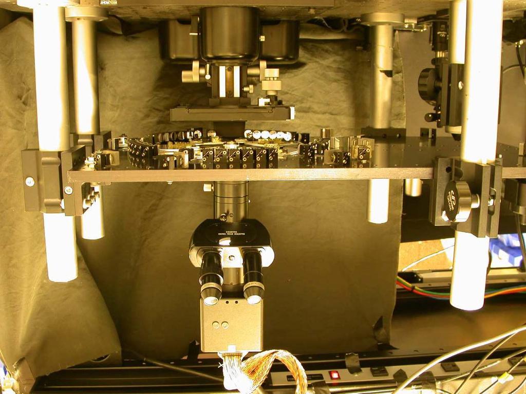
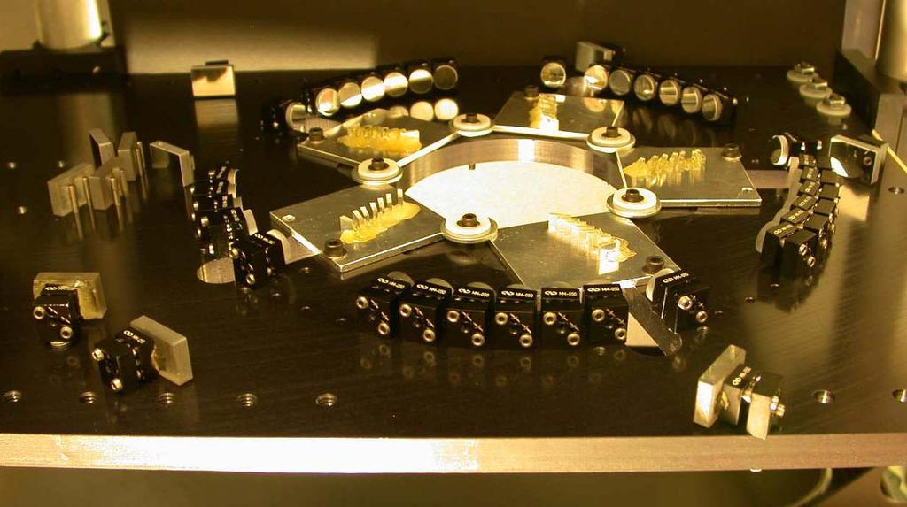
16 SAM M6

17 Creating Interference Pattern

18 Creating Interference Pattern
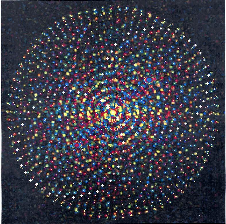
19 Fourier Transform of Texture Pattern

20 Interference Pattern Texture
21 Synthetic Aperture Microscopy Interference of many Coherent Beams Amplitude and Phase Control of Beams

22 Amplitude and Phase Control

23 Amplitude and Phase Control
24 Synthetic Aperture Microscopy Interference of many Coherent Beams Amplitude and Phase Control of Beams On the fly calibration Non-uniform inverse FT Least Squares

25 Wavenumber Calibration using FT

26 Hough Transform Calibration
27 Least Squares Match in FT
28 Fourier Transform of Texture Pattern

29 Uneven Fourier Sampling

30 Polystyrene Micro Beads (1µm)
31 Resolution Enhancement Reflective Optics Illumination Vaccum UV Short Wavelength
32 Reflective Optics M6
33 Resolution Enhancement Reflective Optics Illumination Vaccum UV Short Wavelength Fluorescence Mode Resolution Determined by Illumination


34 Synthetic Aperture Lithography Create pattern controlled interference Example: Two Dots Example: Straight Line Destructive interference safe zone Example: Bessel Ring.
35 (2) CODED APERTURE IMAGING Can t refract or reflect gamma rays Pinhole tradeoff resolution and SNR with: Richard Lanza, Roberto Accorsi, Klaus Ziock, and Lorenzo Fabris.
36 Coded Aperture Imaging Can t refract or reflect gamma rays Pinhole tradeoff resolution and SNR Multiple pinholes Complex masks can cast shadows

37 Masks Fresnel Camera

38 Coded Aperture Principle

39 Decoding Method Rationale
40 Coded Aperture Imaging Can t refract or reflect gamma rays Pinhole tradeoff resolution and SNR Complex masks can cast shadows Decoding by Correlation Special Masks with Flat Power Spectrum
41 Mask Design Inverse Systems
42 Maximizing SNR n n min w 2 i subject to w i = 1 i=1 i=1 yields w i = 1 n

43 Masks Legri URA

44 Masks XRT Coarse
45 Mask Design 1D Definition: q is a quadratic residue (mod p) if n s.t. n 2 q(mod p) Legendre symbol ( a ) p = 1 { 1 if a is quadratic residue otherwise Correlation with zero shift (p 1)/2 Correlation with non-zero shift (p 1)/4
46 Mask Design Auto Correlation a(i) = (p 1) 4 (1 + δ(i)) Power Spectrum A(j) = (p 1) (δ(j) + 1) 4

47 Masks Hexagonal
48 Coded Aperture Extensions Artifacts due to Finite Distance Mask / Countermask Combination
49
50

51 Coded Aperture Backprojection Reconstruction Animation
52 Coded Aperture Extensions Artifacts due to Finite Distance Mask / Countermask Combination Multiple Detector Array Positions Synthetic Aperture radiography
53 Coded Aperture Applications Detection of Fissile Material Large Area Detector Myth Signal and Background Amplified
54 Spatially Varying Background
55 Large Area Alone Doesn t Help

56 Imaging and Large Area Do!

57 Coded Aperture Example Imaging 1/R instead of 1/R 2

58 Coded Aperture Detector Array

59 Computational Imaging System

60 Coded Aperture Example Three weak, distant radioactive sources Reconstruction Animation
61 Coded Aperture Applications Detection of Fissile Material Imaging 1/R instead of 1/R 2 Increasing Gamma Camera Resolution Replacing Rats with Mice.
62 (3) DIAPHANOGRAPHY (Diffuse Optical Tomography) Highly Scattering Low Absorption Many Sources Many Detectors with: Xiaochun Yang, Richard Lanza, Charles Sodini, and John Wyatt.
63 Diaphanography Randomization of Direction Scalar Flux Density
64 Diaphanography Approximation: Diffusion Equation v(x,y) + ρ(x,y)c(x,y) = 0 v(x,y) flux density ρ(x, y) scattering coefficient c(x,y) absorption coefficient Forward: given c(x,y) find v(x,y)
65 Diaphanography Approximation: Diffusion Equation Leaky Resistive Sheet Analog (2D)
66 Diaphanography Invert Diffusion Equation Regions of Influence.
67 (4) EXACT CONE BEAM ALGORITHM Faster Scanning Fewer Motion Artifacts Lower Exposure Uniform Resolution with: Xiaochun Yang
68 Exact Cone Beam Reconstruction Faster Scanning Fewer Motion Artifacts Lower Exposure Uniform Resolution Parallel Beam Fan Beam Planar Fan Cone Beam


69 Parallel Beam to Fan Beam Coordinate Transform in 2D Radon Space
70 Cone Beam Geometry 3D
71 Radon s Formula In 2D: ~ derivatives of line integrals In 3D: derivatives of plane integrals Can t get plane integrals from projections ( ) f (r, θ)dr dθ 1 f (x, y) dx dy r
72 Radon s Formula in 3D f(x) = 1 8π 2 2 R f (l, β) S 2 l 2 l=x β dβ where R f (l, β) = f(x) δ(x β l)dv
 dx dy = f (r, φ, θ) dr dφ")
73 Grangeat s Trick z f (x, y, z) dx dy = f (r, φ, θ) dr dφ θ
74 Exact Cone Beam Reconstruction Data Sufficiency Condition Good Orbit for Radiation Source
75 Radon Space 2D

76 Circular Orbit is Inadequate (3D)
77 Data Insufficiency
78 Good Source Orbit
79 Exact Cone Beam Reconstruction Data Sufficiency Condition Good Orbit for Radiation Source Practical Issue: Spiral CT Scanners Practical Issue: Long Body Problem.
80 COMPUTATIONAL IMAGING (1) Synthetic Aperture Imaging (2) Coded Aperture Imaging (3) Diaphanography Diffuse Tomography (4) Exact Cone Beam Reconstruction
81 COMPUTATIONAL IMAGING
Introduction. Chapter 16 Diagnostic Radiology. Primary radiological image. Primary radiological image
 Introduction Chapter 16 Diagnostic Radiology Radiation Dosimetry I Text: H.E Johns and J.R. Cunningham, The physics of radiology, 4 th ed. http://www.utoledo.edu/med/depts/radther In diagnostic radiology
Sensitive measurement of partial coherence using a pinhole array
 1.3 Sensitive measurement of partial coherence using a pinhole array Paul Petruck 1, Rainer Riesenberg 1, Richard Kowarschik 2 1 Institute of Photonic Technology, Albert-Einstein-Strasse 9, 07747 Jena,
Point Spread Function. Confocal Laser Scanning Microscopy. Confocal Aperture. Optical aberrations. Alternative Scanning Microscopy
 Bi177 Lecture 5 Adding the Third Dimension Wide-field Imaging Point Spread Function Deconvolution Confocal Laser Scanning Microscopy Confocal Aperture Optical aberrations Alternative Scanning Microscopy
3D light microscopy techniques
 3D light microscopy techniques The image of a point is a 3D feature In-focus image Out-of-focus image The image of a point is not a point Point Spread Function (PSF) 1D imaging 2D imaging 3D imaging Resolution
PHY 431 Homework Set #5 Due Nov. 20 at the start of class
 PHY 431 Homework Set #5 Due Nov. 0 at the start of class 1) Newton s rings (10%) The radius of curvature of the convex surface of a plano-convex lens is 30 cm. The lens is placed with its convex side down
Lab Report 3: Speckle Interferometry LIN PEI-YING, BAIG JOVERIA
 Lab Report 3: Speckle Interferometry LIN PEI-YING, BAIG JOVERIA Abstract: Speckle interferometry (SI) has become a complete technique over the past couple of years and is widely used in many branches of
Development of ultra-fine structure t metrology system using coherent EUV source
 2009 International Workshop On EUV Lithography, July 13-17,2009 Development of ultra-fine structure t metrology system using coherent EUV source University of Hyogo 1, Hiroo Kinoshita 1,3, Tetuo Harada
TSBB09 Image Sensors 2018-HT2. Image Formation Part 1
 TSBB09 Image Sensors 2018-HT2 Image Formation Part 1 Basic physics Electromagnetic radiation consists of electromagnetic waves With energy That propagate through space The waves consist of transversal
EE-527: MicroFabrication
 EE-57: MicroFabrication Exposure and Imaging Photons white light Hg arc lamp filtered Hg arc lamp excimer laser x-rays from synchrotron Electrons Ions Exposure Sources focused electron beam direct write
An Activity in Computed Tomography
 Pre-lab Discussion An Activity in Computed Tomography X-rays X-rays are high energy electromagnetic radiation with wavelengths smaller than those in the visible spectrum (0.01-10nm and 4000-800nm respectively).
Test procedures Page: 1 of 5
 Test procedures Page: 1 of 5 1 Scope This part of document establishes uniform requirements for measuring the numerical aperture of optical fibre, thereby assisting in the inspection of fibres and cables
An Activity in Computed Tomography
 Pre-lab Discussion An Activity in Computed Tomography X-rays X-rays are high energy electromagnetic radiation with wavelengths smaller than those in the visible spectrum (0.01-10nm and 4000-800nm respectively).
The Formation of an Aerial Image, part 3
 T h e L i t h o g r a p h y T u t o r (July 1993) The Formation of an Aerial Image, part 3 Chris A. Mack, FINLE Technologies, Austin, Texas In the last two issues, we described how a projection system
Lithography. 3 rd. lecture: introduction. Prof. Yosi Shacham-Diamand. Fall 2004
 Lithography 3 rd lecture: introduction Prof. Yosi Shacham-Diamand Fall 2004 1 List of content Fundamental principles Characteristics parameters Exposure systems 2 Fundamental principles Aerial Image Exposure
3D light microscopy techniques
 3D light microscopy techniques The image of a point is a 3D feature In-focus image Out-of-focus image The image of a point is not a point Point Spread Function (PSF) 1D imaging 1 1 2! NA = 0.5! NA 2D imaging
Diffraction. Interference with more than 2 beams. Diffraction gratings. Diffraction by an aperture. Diffraction of a laser beam
 Diffraction Interference with more than 2 beams 3, 4, 5 beams Large number of beams Diffraction gratings Equation Uses Diffraction by an aperture Huygen s principle again, Fresnel zones, Arago s spot Qualitative
Diffraction, Fourier Optics and Imaging
 1 Diffraction, Fourier Optics and Imaging 1.1 INTRODUCTION When wave fields pass through obstacles, their behavior cannot be simply described in terms of rays. For example, when a plane wave passes through
Spatial-Phase-Shift Imaging Interferometry Using Spectrally Modulated White Light Source
 Spatial-Phase-Shift Imaging Interferometry Using Spectrally Modulated White Light Source Shlomi Epshtein, 1 Alon Harris, 2 Igor Yaacobovitz, 1 Garrett Locketz, 3 Yitzhak Yitzhaky, 4 Yoel Arieli, 5* 1AdOM
An EM Reconstruction with Improved Signal-to. to-noise Ratio for Coded Aperture Imaging
 An EM Reconstruction with Improved Signal-to to-noise Ratio for Coded Aperture Imaging Cynthia Tozian, PhD UMass Lowell Bristol-Myers Squibb Medical Imaging Young Investigators Symposium April 12, 2006
Aberrations and adaptive optics for biomedical microscopes
 Aberrations and adaptive optics for biomedical microscopes Martin Booth Department of Engineering Science And Centre for Neural Circuits and Behaviour University of Oxford Outline Rays, wave fronts and
PD233: Design of Biomedical Devices and Systems
 PD233: Design of Biomedical Devices and Systems (Lecture-8 Medical Imaging Systems) (Imaging Systems Basics, X-ray and CT) Dr. Manish Arora CPDM, IISc Course Website: http://cpdm.iisc.ac.in/utsaah/courses/
Synchrotron X-ray tomographic microscopy Theory vs. practice
 Synchrotron X-ray tomographic microscopy Theory vs. practice Federica Marone Swiss Light Source, Paul Scherrer Institut, Villigen, Switzerland Theory Radon transform Rf x = Beer-Lambert law I E = I 0 (E)e
Applying the Filtered Back-Projection Method to Extract Signal at Specific Position
 Applying the Filtered Back-Projection Method to Extract Signal at Specific Position 1 Chia-Ming Chang and Chun-Hao Peng Department of Computer Science and Engineering, Tatung University, Taipei, Taiwan
Interference [Hecht Ch. 9]
![Interference [Hecht Ch. 9]](/thumbs/79/79365345.jpg "Interference [Hecht Ch. 9]") Interference [Hecht Ch. 9] Note: Read Ch. 3 & 7 E&M Waves and Superposition of Waves and Meet with TAs and/or Dr. Lai if necessary. General Consideration 1 2 Amplitude Splitting Interferometers If a lightwave
Interference [Hecht Ch. 9] Note: Read Ch. 3 & 7 E&M Waves and Superposition of Waves and Meet with TAs and/or Dr. Lai if necessary. General Consideration 1 2 Amplitude Splitting Interferometers If a lightwave
Study of self-interference incoherent digital holography for the application of retinal imaging
 Study of self-interference incoherent digital holography for the application of retinal imaging Jisoo Hong and Myung K. Kim Department of Physics, University of South Florida, Tampa, FL, US 33620 ABSTRACT
The Formation of an Aerial Image, part 2
 T h e L i t h o g r a p h y T u t o r (April 1993) The Formation of an Aerial Image, part 2 Chris A. Mack, FINLE Technologies, Austin, Texas In the last issue, we began to described how a projection system
ANECHOIC CHAMBER DIAGNOSTIC IMAGING
 ANECHOIC CHAMBER DIAGNOSTIC IMAGING Greg Hindman Dan Slater Nearfield Systems Incorporated 1330 E. 223rd St. #524 Carson, CA 90745 USA (310) 518-4277 Abstract Traditional techniques for evaluating the
Supplementary Figure 1. GO thin film thickness characterization. The thickness of the prepared GO thin
 Supplementary Figure 1. GO thin film thickness characterization. The thickness of the prepared GO thin film is characterized by using an optical profiler (Bruker ContourGT InMotion). Inset: 3D optical
Image Formation. Light from distant things. Geometrical optics. Pinhole camera. Chapter 36
 Light from distant things Chapter 36 We learn about a distant thing from the light it generates or redirects. The lenses in our eyes create images of objects our brains can process. This chapter concerns
Microscope anatomy, image formation and resolution
 Microscope anatomy, image formation and resolution Ian Dobbie Buy this book for your lab: D.B. Murphy, "Fundamentals of light microscopy and electronic imaging", ISBN 0-471-25391-X Visit these websites:
1 Laboratory 7: Fourier Optics
 1051-455-20073 Physical Optics 1 Laboratory 7: Fourier Optics 1.1 Theory: References: Introduction to Optics Pedrottis Chapters 11 and 21 Optics E. Hecht Chapters 10 and 11 The Fourier transform is an
Tangents. The f-stops here. Shedding some light on the f-number. by Marcus R. Hatch and David E. Stoltzmann
 Tangents Shedding some light on the f-number The f-stops here by Marcus R. Hatch and David E. Stoltzmann The f-number has peen around for nearly a century now, and it is certainly one of the fundamental
Fiber Optic Communications
 Fiber Optic Communications ( Chapter 2: Optics Review ) presented by Prof. Kwang-Chun Ho 1 Section 2.4: Numerical Aperture Consider an optical receiver: where the diameter of photodetector surface area
Photolithography II ( Part 2 )
") 1 Photolithography II ( Part 2 ) Chapter 14 : Semiconductor Manufacturing Technology by M. Quirk & J. Serda Saroj Kumar Patra, Department of Electronics and Telecommunication, Norwegian University of Science
1 Photolithography II ( Part 2 ) Chapter 14 : Semiconductor Manufacturing Technology by M. Quirk & J. Serda Saroj Kumar Patra, Department of Electronics and Telecommunication, Norwegian University of Science
7 CHAPTER 7: REFRACTIVE INDEX MEASUREMENTS WITH COMMON PATH PHASE SENSITIVE FDOCT SETUP
 7 CHAPTER 7: REFRACTIVE INDEX MEASUREMENTS WITH COMMON PATH PHASE SENSITIVE FDOCT SETUP Abstract: In this chapter we describe the use of a common path phase sensitive FDOCT set up. The phase measurements
Intorduction to light sources, pinhole cameras, and lenses
 Intorduction to light sources, pinhole cameras, and lenses Erik G. Learned-Miller Department of Computer Science University of Massachusetts, Amherst Amherst, MA 01003 October 26, 2011 Abstract 1 1 Analyzing
( ) Deriving the Lens Transmittance Function. Thin lens transmission is given by a phase with unit magnitude.
 Deriving the Lens Transmittance Function. Thin lens transmission is given by a phase with unit magnitude.") Deriving the Lens Transmittance Function Thin lens transmission is given by a phase with unit magnitude. t(x, y) = exp[ jk o ]exp[ jk(n 1) (x, y) ] Find the thickness function for left half of the lens
Deriving the Lens Transmittance Function Thin lens transmission is given by a phase with unit magnitude. t(x, y) = exp[ jk o ]exp[ jk(n 1) (x, y) ] Find the thickness function for left half of the lens
microscopy A great online resource Molecular Expressions, a Microscope Primer Partha Roy
 Fundamentals of optical microscopy A great online resource Molecular Expressions, a Microscope Primer http://micro.magnet.fsu.edu/primer/index.html Partha Roy 1 Why microscopy Topics Functions of a microscope
Exam 4. Name: Class: Date: Multiple Choice Identify the choice that best completes the statement or answers the question.
 Name: Class: Date: Exam 4 Multiple Choice Identify the choice that best completes the statement or answers the question. 1. Mirages are a result of which physical phenomena a. interference c. reflection
Reflection! Reflection and Virtual Image!
 1/30/14 Reflection - wave hits non-absorptive surface surface of a smooth water pool - incident vs. reflected wave law of reflection - concept for all electromagnetic waves - wave theory: reflected back
Laser Speckle Reducer LSR-3000 Series
 Datasheet: LSR-3000 Series Update: 06.08.2012 Copyright 2012 Optotune Laser Speckle Reducer LSR-3000 Series Speckle noise from a laser-based system is reduced by dynamically diffusing the laser beam. A
Observational Astronomy
 Observational Astronomy Instruments The telescope- instruments combination forms a tightly coupled system: Telescope = collecting photons and forming an image Instruments = registering and analyzing the
Cameras. Steve Rotenberg CSE168: Rendering Algorithms UCSD, Spring 2017
 Cameras Steve Rotenberg CSE168: Rendering Algorithms UCSD, Spring 2017 Camera Focus Camera Focus So far, we have been simulating pinhole cameras with perfect focus Often times, we want to simulate more
Infrared Single Shot Diagnostics for the Longitudinal. Profile of the Electron Bunches at FLASH. Disputation
 Infrared Single Shot Diagnostics for the Longitudinal Profile of the Electron Bunches at FLASH Disputation Hossein Delsim-Hashemi Tuesday 22 July 2008 7/23/2008 2/ 35 Introduction m eb c 2 3 2 γ ω = +
FRAUNHOFER AND FRESNEL DIFFRACTION IN ONE DIMENSION
 FRAUNHOFER AND FRESNEL DIFFRACTION IN ONE DIMENSION Revised November 15, 2017 INTRODUCTION The simplest and most commonly described examples of diffraction and interference from two-dimensional apertures
Advanced Features of InfraTec Pyroelectric Detectors
 1 Basics and Application of Variable Color Products The key element of InfraTec s variable color products is a silicon micro machined tunable narrow bandpass filter, which is fully integrated inside the
Confocal Imaging Through Scattering Media with a Volume Holographic Filter
 Confocal Imaging Through Scattering Media with a Volume Holographic Filter Michal Balberg +, George Barbastathis*, Sergio Fantini % and David J. Brady University of Illinois at Urbana-Champaign, Urbana,
Properties of Structured Light
 Properties of Structured Light Gaussian Beams Structured light sources using lasers as the illumination source are governed by theories of Gaussian beams. Unlike incoherent sources, coherent laser sources
Bragg and fiber gratings. Mikko Saarinen
 Bragg and fiber gratings Mikko Saarinen 27.10.2009 Bragg grating - Bragg gratings are periodic perturbations in the propagating medium, usually periodic variation of the refractive index - like diffraction
Εισαγωγική στην Οπτική Απεικόνιση
 Εισαγωγική στην Οπτική Απεικόνιση Δημήτριος Τζεράνης, Ph.D. Εμβιομηχανική και Βιοϊατρική Τεχνολογία Τμήμα Μηχανολόγων Μηχανικών Ε.Μ.Π. Χειμερινό Εξάμηνο 2015 Light: A type of EM Radiation EM radiation:
Micro- and Nano-Technology... for Optics
 Micro- and Nano-Technology...... for Optics 3.2 Lithography U.D. Zeitner Fraunhofer Institut für Angewandte Optik und Feinmechanik Jena Printing on Stones Map of Munich Stone Print Contact Printing light
Supplementary Figure 1. Effect of the spacer thickness on the resonance properties of the gold and silver metasurface layers.
 Supplementary Figure 1. Effect of the spacer thickness on the resonance properties of the gold and silver metasurface layers. Finite-difference time-domain calculations of the optical transmittance through
Receiver Performance and Comparison of Incoherent (bolometer) and Coherent (receiver) detection
 and Coherent (receiver) detection") At ev gap /h the photons have sufficient energy to break the Cooper pairs and the SIS performance degrades. Receiver Performance and Comparison of Incoherent (bolometer) and Coherent (receiver) detection
At ev gap /h the photons have sufficient energy to break the Cooper pairs and the SIS performance degrades. Receiver Performance and Comparison of Incoherent (bolometer) and Coherent (receiver) detection
Moving from film to digital: A study of digital x-ray benefits, challenges and best practices
 Moving from film to digital: A study of digital x-ray benefits, challenges and best practices H.U. Pöhler 1 and N. D Ademo 2 DÜRR NDT GmbH & Co. KG, Höpfigheimer Straße 22, Bietigheim-Bissingen, 74321,
Optical Projection Printing and Modeling
 Optical Projection Printing and Modeling Overview of optical lithography, concepts, trends Basic Parameters and Effects (1-14) Resolution Depth of Focus; Proximity, MEEF, LES Image Calculation, Characterization
Study of Graded Index and Truncated Apertures Using Speckle Images
 Study of Graded Index and Truncated Apertures Using Speckle Images A. M. Hamed Department of Physics, Faculty of Science, Ain Shams University, Cairo, 11566 Egypt amhamed73@hotmail.com Abstract- In this
An Introduction: Radon Transform, X-ray Transform, Inverse Problems
 Other applications: SPECT and Attenuated An Introduction:, X-ray Transform, TING ZHOU Northeastern University January 9, 2018 Other applications: SPECT and Attenuated Outline 1 Course Information (syllabus,
ONE of the most common and robust beamforming algorithms
 TECHNICAL NOTE 1 Beamforming algorithms - beamformers Jørgen Grythe, Norsonic AS, Oslo, Norway Abstract Beamforming is the name given to a wide variety of array processing algorithms that focus or steer
Collimation Tester Instructions
 Description Use shear-plate collimation testers to examine and adjust the collimation of laser light, or to measure the wavefront curvature and divergence/convergence magnitude of large-radius optical
Laser Telemetric System (Metrology)
") Laser Telemetric System (Metrology) Laser telemetric system is a non-contact gauge that measures with a collimated laser beam (Refer Fig. 10.26). It measure at the rate of 150 scans per second. It basically
Laser Telemetric System (Metrology) Laser telemetric system is a non-contact gauge that measures with a collimated laser beam (Refer Fig. 10.26). It measure at the rate of 150 scans per second. It basically
Coded Computational Photography!
 Coded Computational Photography! EE367/CS448I: Computational Imaging and Display! stanford.edu/class/ee367! Lecture 9! Gordon Wetzstein! Stanford University! Coded Computational Photography - Overview!!
Dynamically Reparameterized Light Fields & Fourier Slice Photography. Oliver Barth, 2009 Max Planck Institute Saarbrücken
 Dynamically Reparameterized Light Fields & Fourier Slice Photography Oliver Barth, 2009 Max Planck Institute Saarbrücken Background What we are talking about? 2 / 83 Background What we are talking about?
Submillimeter (continued)
") Submillimeter (continued) Dual Polarization, Sideband Separating Receiver Dual Mixer Unit The 12-m Receiver Here is where the receiver lives, at the telescope focus Receiver Performance T N (noise temperature)
Submillimeter (continued) Dual Polarization, Sideband Separating Receiver Dual Mixer Unit The 12-m Receiver Here is where the receiver lives, at the telescope focus Receiver Performance T N (noise temperature)
Design of a digital holographic interferometer for the. ZaP Flow Z-Pinch
 Design of a digital holographic interferometer for the M. P. Ross, U. Shumlak, R. P. Golingo, B. A. Nelson, S. D. Knecht, M. C. Hughes, R. J. Oberto University of Washington, Seattle, USA Abstract The
MICROCHIP MANUFACTURING by S. Wolf
 MICROCHIP MANUFACTURING by S. Wolf Chapter 19 LITHOGRAPHY II: IMAGE-FORMATION and OPTICAL HARDWARE 2004 by LATTICE PRESS CHAPTER 19 - CONTENTS Preliminaries: Wave- Motion & The Behavior of Light Resolution
Chapter 4: Fourier Optics
 Chapter 4: Fourier Optics P4-1. Calculate the Fourier transform of the function rect(2x)rect(/3) The rectangular function rect(x) is given b 1 x 1/2 rect( x) when 0 x 1/2 P4-2. Assume that ( gx (, )) G
Optical Lithography. Here Is Why. Burn J. Lin SPIE PRESS. Bellingham, Washington USA
 Optical Lithography Here Is Why Burn J. Lin SPIE PRESS Bellingham, Washington USA Contents Preface xiii Chapter 1 Introducing Optical Lithography /1 1.1 The Role of Lithography in Integrated Circuit Fabrication
ANTENNA THEORY. Analysis and Design. CONSTANTINE A. BALANIS Arizona State University. JOHN WILEY & SONS New York Chichester Brisbane Toronto Singapore
 ANTENNA THEORY Analysis and Design CONSTANTINE A. BALANIS Arizona State University JOHN WILEY & SONS New York Chichester Brisbane Toronto Singapore Contents Preface xv Chapter 1 Antennas 1 1.1 Introduction
Physics 431 Final Exam Examples (3:00-5:00 pm 12/16/2009) TIME ALLOTTED: 120 MINUTES Name: Signature:
 TIME ALLOTTED: 120 MINUTES Name: Signature:") Physics 431 Final Exam Examples (3:00-5:00 pm 12/16/2009) TIME ALLOTTED: 120 MINUTES Name: PID: Signature: CLOSED BOOK. TWO 8 1/2 X 11 SHEET OF NOTES (double sided is allowed), AND SCIENTIFIC POCKET CALCULATOR
Physics 431 Final Exam Examples (3:00-5:00 pm 12/16/2009) TIME ALLOTTED: 120 MINUTES Name: PID: Signature: CLOSED BOOK. TWO 8 1/2 X 11 SHEET OF NOTES (double sided is allowed), AND SCIENTIFIC POCKET CALCULATOR
Optical Issues in Photolithography
 OpenStax-CNX module: m25448 1 Optical Issues in Photolithography Andrew R. Barron This work is produced by OpenStax-CNX and licensed under the Creative Commons Attribution License 3.0 note: This module
Supplementary Information for. Surface Waves. Angelo Angelini, Elsie Barakat, Peter Munzert, Luca Boarino, Natascia De Leo,
 Supplementary Information for Focusing and Extraction of Light mediated by Bloch Surface Waves Angelo Angelini, Elsie Barakat, Peter Munzert, Luca Boarino, Natascia De Leo, Emanuele Enrico, Fabrizio Giorgis,
Section 2: Lithography. Jaeger Chapter 2 Litho Reader. The lithographic process
 Section 2: Lithography Jaeger Chapter 2 Litho Reader The lithographic process Photolithographic Process (a) (b) (c) (d) (e) (f) (g) Substrate covered with silicon dioxide barrier layer Positive photoresist
Physics 202, Lecture 28
 Physics 202, Lecture 28 Today s Topics Michelson Interferometer iffraction Single Slit iffraction Multi-Slit Interference iffraction on Circular Apertures The Rayleigh Criterion Wave Superposition Using
Low Spatial Frequency Noise Reduction with Applications to Light Field Moment Imaging
 Low Spatial Frequency Noise Reduction with Applications to Light Field Moment Imaging Christopher Madsen Stanford University cmadsen@stanford.edu Abstract This project involves the implementation of multiple
Optics and Lasers. Matt Young. Including Fibers and Optical Waveguides
 Matt Young Optics and Lasers Including Fibers and Optical Waveguides Fourth Revised Edition With 188 Figures Springer-Verlag Berlin Heidelberg New York London Paris Tokyo Hong Kong Barcelona Budapest Contents
Microscopy Training & Overview
 Microscopy Training & Overview Product Marketing October 2011 Stephan Briggs - PLE OVERVIEW AND PRESENTATION FLOW Glossary and Important Terms Introduction Timeline Innovation and Advancement Primary Components
Section 2: Lithography. Jaeger Chapter 2. EE143 Ali Javey Slide 5-1
 Section 2: Lithography Jaeger Chapter 2 EE143 Ali Javey Slide 5-1 The lithographic process EE143 Ali Javey Slide 5-2 Photolithographic Process (a) (b) (c) (d) (e) (f) (g) Substrate covered with silicon
MODULE P6: THE WAVE MODEL OF RADIATION OVERVIEW
 OVERVIEW Wave behaviour explains a great many phenomena, both natural and artificial, for all waves have properties in common. The first topic introduces a basic vocabulary for describing waves. Reflections
Section 2: Lithography. Jaeger Chapter 2 Litho Reader. EE143 Ali Javey Slide 5-1
 Section 2: Lithography Jaeger Chapter 2 Litho Reader EE143 Ali Javey Slide 5-1 The lithographic process EE143 Ali Javey Slide 5-2 Photolithographic Process (a) (b) (c) (d) (e) (f) (g) Substrate covered
Purpose: Explain the top 10 phenomena and concepts. BPP-1: Resolution and Depth of Focus (1.5X)
") Basic Projection Printing (BPP) Modules Purpose: Explain the top 10 phenomena and concepts key to understanding optical projection printing BPP-1: Resolution and Depth of Focus (1.5X) BPP-2: Bragg condition
Basic Projection Printing (BPP) Modules Purpose: Explain the top 10 phenomena and concepts key to understanding optical projection printing BPP-1: Resolution and Depth of Focus (1.5X) BPP-2: Bragg condition
MASSACHUSETTS INSTITUTE OF TECHNOLOGY Mechanical Engineering Department. 2.71/2.710 Final Exam. May 21, Duration: 3 hours (9 am-12 noon)
") MASSACHUSETTS INSTITUTE OF TECHNOLOGY Mechanical Engineering Department 2.71/2.710 Final Exam May 21, 2013 Duration: 3 hours (9 am-12 noon) CLOSED BOOK Total pages: 5 Name: PLEASE RETURN THIS BOOKLET WITH
MASSACHUSETTS INSTITUTE OF TECHNOLOGY Mechanical Engineering Department 2.71/2.710 Final Exam May 21, 2013 Duration: 3 hours (9 am-12 noon) CLOSED BOOK Total pages: 5 Name: PLEASE RETURN THIS BOOKLET WITH
Image acquisition. In both cases, the digital sensing element is one of the following: Line array Area array. Single sensor
 Image acquisition Digital images are acquired by direct digital acquisition (digital still/video cameras), or scanning material acquired as analog signals (slides, photographs, etc.). In both cases, the
Optical Signal Processing
 Optical Signal Processing ANTHONY VANDERLUGT North Carolina State University Raleigh, North Carolina A Wiley-Interscience Publication John Wiley & Sons, Inc. New York / Chichester / Brisbane / Toronto
VISUAL PHYSICS ONLINE DEPTH STUDY: ELECTRON MICROSCOPES
 VISUAL PHYSICS ONLINE DEPTH STUDY: ELECTRON MICROSCOPES Shortly after the experimental confirmation of the wave properties of the electron, it was suggested that the electron could be used to examine objects
Lecture Notes Prepared by Prof. J. Francis Spring Remote Sensing Instruments
 Lecture Notes Prepared by Prof. J. Francis Spring 2005 Remote Sensing Instruments Material from Remote Sensing Instrumentation in Weather Satellites: Systems, Data, and Environmental Applications by Rao,
FDTD Analysis of Readout Characteristics in a near-field MAMMOS recording system. Matthew Manfredonia Paul Nutter & David Wright
 FDTD Analysis of Readout Characteristics in a near-field MAMMOS recording system Matthew Manfredonia Paul Nutter & David Wright Electronic & Information Storage Systems Research Group School of Computer
OCT Spectrometer Design Understanding roll-off to achieve the clearest images
 OCT Spectrometer Design Understanding roll-off to achieve the clearest images Building a high-performance spectrometer for OCT imaging requires a deep understanding of the finer points of both OCT theory
Draw and label this wave: - What do waves transfer? (They do this without transferring what?) What do all electromagnetic waves have in common?
 What do all electromagnetic waves have in common?") What do waves transfer? Draw and label this wave: - (They do this without transferring what?) What do all electromagnetic waves have in common? Name the electromagnetic spectrum from shortest to longest
What do waves transfer? Draw and label this wave: - (They do this without transferring what?) What do all electromagnetic waves have in common? Name the electromagnetic spectrum from shortest to longest
PICO MASTER 200. UV direct laser writer for maskless lithography
 PICO MASTER 200 UV direct laser writer for maskless lithography 4PICO B.V. Jan Tinbergenstraat 4b 5491 DC Sint-Oedenrode The Netherlands Tel: +31 413 490708 WWW.4PICO.NL 1. Introduction The PicoMaster
BMB/Bi/Ch 173 Winter 2018
 BMB/Bi/Ch 73 Winter 208 Homework Set 2 (200 Points) Assigned -7-8, due -23-8 by 0:30 a.m. TA: Rachael Kuintzle. Office hours: SFL 229, Friday /9 4:00-5:00pm and SFL 220, Monday /22 4:00-5:30pm. For the
Resolution. [from the New Merriam-Webster Dictionary, 1989 ed.]:
![Resolution. [from the New Merriam-Webster Dictionary, 1989 ed.]:](/thumbs/71/66141426.jpg "Resolution. [from the New Merriam-Webster Dictionary, 1989 ed.]:") Resolution [from the New Merriam-Webster Dictionary, 1989 ed.]: resolve v : 1 to break up into constituent parts: ANALYZE; 2 to find an answer to : SOLVE; 3 DETERMINE, DECIDE; 4 to make or pass a formal
Resolution [from the New Merriam-Webster Dictionary, 1989 ed.]: resolve v : 1 to break up into constituent parts: ANALYZE; 2 to find an answer to : SOLVE; 3 DETERMINE, DECIDE; 4 to make or pass a formal
Spatially Resolved Backscatter Ceilometer
 Spatially Resolved Backscatter Ceilometer Design Team Hiba Fareed, Nicholas Paradiso, Evan Perillo, Michael Tahan Design Advisor Prof. Gregory Kowalski Sponsor, Spectral Sciences Inc. Steve Richstmeier,
APPLICATION NOTE
 THE PHYSICS BEHIND TAG OPTICS TECHNOLOGY AND THE MECHANISM OF ACTION OF APPLICATION NOTE 12-001 USING SOUND TO SHAPE LIGHT Page 1 of 6 Tutorial on How the TAG Lens Works This brief tutorial explains the
Introduction to Interferometry. Michelson Interferometer. Fourier Transforms. Optics: holes in a mask. Two ways of understanding interferometry
 Introduction to Interferometry P.J.Diamond MERLIN/VLBI National Facility Jodrell Bank Observatory University of Manchester ERIS: 5 Sept 005 Aim to lay the groundwork for following talks Discuss: General
1. INTRODUCTION ABSTRACT
 Experimental verification of Sub-Wavelength Holographic Lithography physical concept for single exposure fabrication of complex structures on planar and non-planar surfaces Michael V. Borisov, Dmitry A.
Acquisition Basics. How can we measure material properties? Goal of this Section. Special Purpose Tools. General Purpose Tools
 Course 10 Realistic Materials in Computer Graphics Acquisition Basics MPI Informatik (moving to the University of Washington Goal of this Section practical, hands-on description of acquisition basics general
Talbot- Lau interferometry with a non- binary phase grating for non-destructive testing
 19 th World Conference on Non-Destructive Testing 2016 Talbot- Lau interferometry with a non- binary phase grating for non-destructive testing Yury SHASHEV 1, Andreas KUPSCH 1, Axel LANGE 1, Ralf BRITZKE
Microlens array-based exit pupil expander for full color display applications
 Proc. SPIE, Vol. 5456, in Photon Management, Strasbourg, France, April 2004 Microlens array-based exit pupil expander for full color display applications Hakan Urey a, Karlton D. Powell b a Optical Microsystems
Principles of Optics for Engineers
 Principles of Optics for Engineers Uniting historically different approaches by presenting optical analyses as solutions of Maxwell s equations, this unique book enables students and practicing engineers
Education in Microscopy and Digital Imaging
 Contact Us Carl Zeiss Education in Microscopy and Digital Imaging ZEISS Home Products Solutions Support Online Shop ZEISS International ZEISS Campus Home Interactive Tutorials Basic Microscopy Spectral