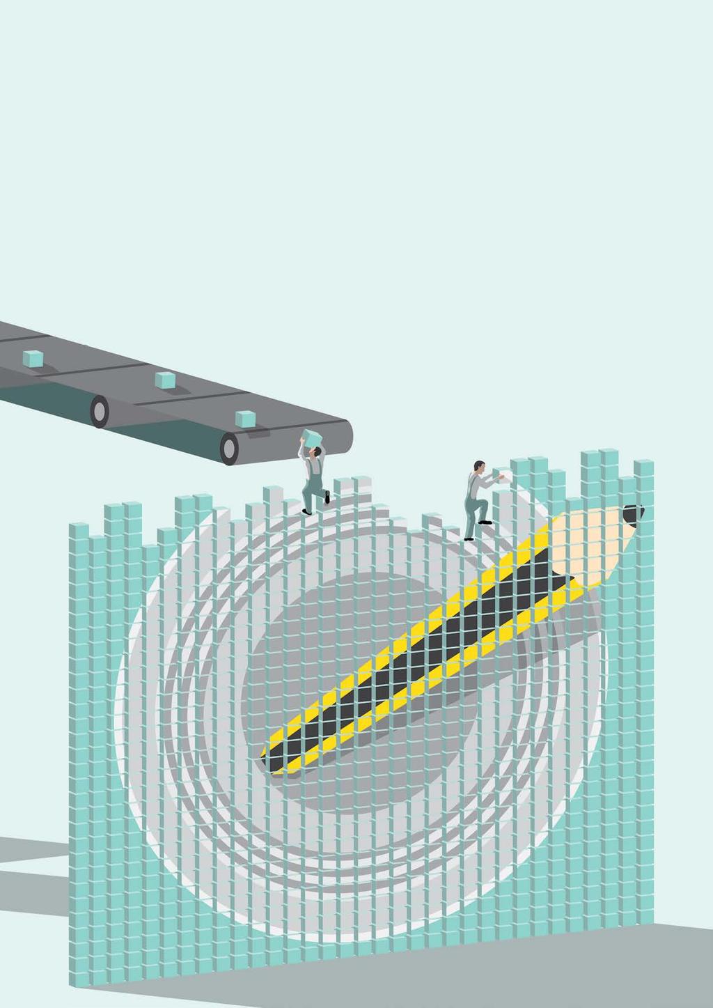
Cameras. Fig. 2: Camera obscura View of Hotel de Ville, Paris, France, 2015 Photo by Abelardo Morell
|
|
|
- Angela Kelly
- 6 years ago
- Views:
Transcription
 that converts intensity and frequency of the electromagnetic radiation to information, through chemical or")
1 Cameras camera is a remote sensing device that can capture and store or transmit images. Light is A collected and focused through an optical system on a sensitive surface (sensor) that converts intensity and frequency of the electromagnetic radiation to information, through chemical or electronic processes. The simplest system of this kind consists of a dark room or box in which light enters only from a small hole and is focused on the opposite wall, where it can be seen by the eye or captured on a light sensitive material (i.e. photographic film). This imaging method, which dates back centuries, is called camera obscura (latin for dark room ), and gave the name to modern cameras. Fig. 1: Working principle of a camera obscura Fig. 2: Camera obscura View of Hotel de Ville, Paris, France, 2015 Photo by Abelardo Morell Camera technology has hugely improved in the last decades, since the development of Charge Coupled Device (CCD) and, more recently, of CMOS technology. Previous standard systems, such as vacuum tube cameras, have been discontinued. The improvements in image resolution and acquisition speed obviously also improved the quality and speed of machine vision cameras.

2
3
4 Camera types Matrix and Line scan cameras Cameras used in machine vision applications can be divided in two groups: area scan cameras (also called matrix cameras) and line scan cameras. The first are simpler and less technically demanding, while the latter are preferred in some situations where matrix cameras are not suitable. Area scan cameras capture 2-D images using a certain number of active elements (pixels), while line scan cameras sensors are characterized by a single array of pixels. Sensor sizes and resolution Sensor sizes (or formats) are usually designated with an imperial fraction value i.e. 1/2, 2/3. However, the actual dimensions of a sensor are different from the fraction value, which often causes confusion among users. This practice dates back to the 50 s at the time of TV camera tubes and is still the standard these days. Also, it is always wise to check the sensor specifications, since even two sensors with the same format may have slightly different dimensions and aspect ratios. Spatial resolution is the number of active elements (pixels) contained in the sensor area: the higher the resolution, the smaller the detail we can detect on the image. Suppose we need to inspect a 30 x 40 mm FoV, looking for 40*40 μm defects that must be viewed on at least three pixels. There can be 30*40/(0.04*0.04) = 0.75x10^6 defects. Assuming a minimum of 3 pixels are required to see a defect, we need a camera with at least 2.25 MP pixels. This gives the minimum resolution required for the sensor, although the whole system resolution (also including the lens resolution) must always be assessed. Table 1 gives a brief overview of some common sensor dimensions and resolutions. It is important to underline that sensors can have the same dimensions but different resolution, since the pixel size can vary. Although for a given sensor format smaller pixels lead to higher resolution, smaller pixels are not always ideal since they are less sensitive to light and generate higher noise; also, the lens resolution and pixel size must always be properly matched to ensure optimal system performances. Sensor type 1/3 1/2 2/3 1 4/3 4 K (linear) 8 K (linear) 12 K (linear) Sensor size (mm) 4.80 x x x x x Pixel size (μm) Resolution (mm) 960 x x x x x Resolution (Pixel) 0.6 M 1.2 M 2.5 M 5 M 10 M 4 K 8 K 12 K Table 1: Examples of common sensor sizes and resolutions Sensor types: CCD and CMOS The most popular sensor technologies for digital cameras are CCD and CMOS. CCD (charged-couple device) sensors consist of a complex electronic board in which photosensitive semiconductor elements convert photons (light) into electrons. The charge accumulated is proportional to the exposure time. Frame transfer (FT) Full frame (FF) Interline (IL) = Progressive scan Light is collected in a potential well and is then released and read out in different ways (cf. Fig. 3). All architectures basically shift the information to a register, sometimes passing through a passive area for storage. The charge is then amplified to a voltage signal that can be read and quantified. Active & exposed pixel area Passive area for storage and transfer Register pixels for read-out Fig. 3: CCD architectures XLIV
 for the readout.")
5 Cameras CMOS (complementary metal-oxide semiconductor) sensors are conceptually different from CCD sensors, since the readout can be done pixel by pixel rather than in sequential mode. In fact, signal is amplified at each pixel position, allowing you to achieve much higher frame rates and to define custom regions of interest (ROIs) for the readout. CMOS and CCD sensors were invented around the same time and, although historically CCD technology was regarded as superior, in recent years CMOS sensors have caught up in terms of performance. Global and rolling shutter (CMOS). In rolling shutter CMOS sensors, the acquisition is progressive from the upper to the last row of pixels, with up to 1/frame rate time difference between the first and the last row. Once the readout is complete, the progressive acquisition process can start again. If the object is moving, the time difference between pixels is clearly visible on the image, resulting in distorted objects (see Fig. 4). Global shutter is the acquisition method in which all pixels are activated simultaneously, thus avoiding this issue. Sensor and camera features Fig. 4: Rolling shutter effect Sensor characteristics Pixel defects can be of three kinds: hot, warm and dead pixels. Hot pixels are elements that always saturate (give maximum signal, e.g. full white) whichever the light intensity is. Dead pixels behave the opposite, always giving zero (black) signal. Warm pixels produce random signal. These kinds of defects are independent of the intensity and exposure time, so they can be easily removed e.g. by digitally substituting them with the average value of the surrounding pixels. Noise. There are several types of noise that can affect the actual pixel readout. They can be caused by either geometric, physical and electronic factors, and they can be randomly distributed as well as constant. Some of them are presented below: Shot noise is a consequence of the discrete nature of light. When light intensity is very low - as it is considering the small surface of a single pixel the relative fluctuation of the number of photons in time will be significant, in the same way as the heads or tails probability is significantly far from 50% when tossing a coin just a few times. This fluctuation is the shot noise. Dark current noise is caused by the electrons that can be randomly produced by thermal effect. The number of thermal electrons, as well as the related noise, grows with temperature and exposure time. Quantization noise is related to the conversion of the continuous value of the original (analog) voltage value to the discrete value of the processed (digital) voltage. Gain noise is caused by the difference in behavior of different pixels (in terms of sensitivity and gain). This is an example of constant noise that can be measured and eliminated. Sensitivity is a parameter that quantifies how the sensor responds to light. Sensitivity is strictly connected to quantum efficiency, that is the fraction of photons effectively converted into electrons. Dynamic range is the ratio between the maximum and minimum signal that is acquired by the sensor. At the upper limit, pixels appear to be white for every higher value of intensity (saturation), while pixels appear black at the lower limit and below. The dynamic range is usually expressed by the logarithm of the min-max ratio, either in base-10 (decibel) or base-2 (doublings or stops), as shown below. Human eyes, for example, can distinguish objects both under starlight and on a bright sunny day, corresponding to a 90 db difference in intensity. This range, though, cannot be used simultaneously, since the eye needs time to adjust to different light conditions. A good quality LCD has a dynamic range of around 1000:1, and some of the latest CMOS sensors have measured dynamic ranges of about :1 (reported as 14.5 stops). Factor Decibels Stops Table 2: Dynamic range D, Decibels ( 10 log D ) and Stops ( log2 D ) XLV

6 SNR (signal-to-noise ratio) considers the presence of noise, so that the theoretical lowest grey value as defined by the dynamic range is often impossible to achieve. SNR is the ratio between the maximum signal and the overall noise, measured in db. The maximum value for SNR is limited by shot noise (that depends on the physical nature of light, and is this inevitable) and can be approximated as SNR max = sqrt [ maximum saturation capacity in electrons of a single pixel ] SRN gives a limit on the grey levels that are meaningful in the conversion between the analog signal (continuous) and the digital one (discrete). For example, if the maximum SNR is 50 db, a good choice is a 8 bit sensor, in which the 256 grey levels corresponds to 48 db. Using a sensor with higher grey levels would mean registering a certain degree of pure noise. Spectral sensitivity is the parameter describing how efficiently light intensity is registered at different wavelengths. Human eyes have three different kinds of photoreceptors that differ in sensitivity to visible wavelengths, so that the overall sensitivity curve is the combination of all three. Machine vision systems, usually based on CCD or CMOS cameras, detect light from 350 to 900 nm, with the peak zone being between 400 and 650 nm. Different kinds of sensor can also cover the UV spectrum or, on the opposite side, near infrared light, before going to drastically different technology for far wavelengths such as SWIR or LWIR. EMVA Standard 1288 The different parameters that describe the characteristics and quality of a sensor are gathered and coherently described in the EMVA standard This standard illustrates the fundamental parameters that must be given to fully describe the real behavior of a sensor, together with the well-defined measurement methods to get these parameters. The standard parameters are: Sensitivity, linearity of signal versus light intensity and noise Dark current (temperature dependence: optional) Sensor non-uniformity and defect pixels Spectral sensitivity (optional) Sensitivity, linearity and noise Dark current Sensor non-uniformity and defect pixel Spectral sensitivity Measuring procedure Test measuring amount of light at increasing exposure time, from closed shutter to saturation. Quantity of light is measured (e.g. photometer) Measured from dark images taken at increasing exposure times. Since dark current is temperature dependent, behavior at different T can be given A number of images are taken without light (to see hot pixels) and at 50% saturation. Parameters of spatial distortion are calculated using Fourier algorithms Images taken at different wavelengths Quantum efficiency (photons converted over total incoming photons ratio in %) Dark and bright signal non-uniformity Temporal dark noise, in electrons (e-) Dark and bright spectrograms and (logarithmic) histograms Result Absolute sensitivity threshold (minimum number of photons to generate a signal) Dynamic range, in stops Signal registered in absence of light, in electrons per second Spectral sensitivity curve SNR, in stops Saturation capacity (maximum number of electrons at saturation) Camera Parameters Exposure time is the amount of time in which light is allowed to reach the sensor. The higher this value, the higher the quantity of light represented on the resulting image. Increasing the exposure time is the first and easiest solution when light is not enough but it is not free from issues: first, noise always increases with the exposure time; also, blur effects can appear when dealing with moving objects. In fact, if the exposure time is too high, the object will be impressed on a number of different pixels, causing the well-known motion blur effect (see Fig. 5). On the opposite side, too long exposure times can lead to overexposure namely, when a number of pixels reach maximum capacity and thus appear to be white, even if the light intensity on each pixel is actually different Fig. 5: Motion blur effect XLVI
7 Cameras Frame rate. This is the frequency at which a complete image is captured by the sensor, usually expressed in frames per second (fps). It is clear that the frame rate must be adjusted to the application: a line inspecting 1000 bottles per minute must be able to take images with a minimum frame rate of 1000/60 = 17 fps. Triggering. Most cameras give the possibility to control the beginning of the acquisition process, adjusting it to the application. A typical triggering system is one in which light is activated together with the image acquisition after receiving an input from an external device (e.g. position sensor). This technique is essential when taking images of moving objects, in order to ensure that the features of interest are in the field of view of the imaging system. Gain in a digital camera represents the relationship between the number of electrons acquired and the analog-to-digital units (ADUs) generated, i.e. the image signal. Increasing the gain means increasing the ratio between ADUs and electrons acquired, resulting in an apparent higher brightness of the image. Obviously, this process increases the image noise as well, so that the overall SNR will be unchanged. Binning is the camera feature that combines the readout of adjacent pixels on the sensor, usually in rows/columns, more often in 2 x 2 or 4 x 4 squares (see Fig. 6). Although resolution obviously decreases, there are a number of other features improving. For example, with 2x2 binning, resolution is halved, but sensitivity and dynamic range are increased by a factor of 4 (since the capacitiec of each potential well are summed), readout time is halved (frame rate doubled) and noise is quartered. Horizontal binging Charges from two adjacent pixels in the line are summed and reported out as a single pixel. Vertical binging Charges from adjacent pixels in two lines are summed and reported out as a single pixel. Full binging Charges from groups of four pixels are summed and reported out as a single pixel. Fig. 6: Sensor binning Digital camera interfaces Camera Link The Automated Imaging Association (AIA) standard, commonly known as Camera Link, is a standard for high-speed transmission of digital video. AIA standard defines cable, connector and camera functionality between camera and frame grabber. Speed. Camera Link offers very high performance in terms of speed. It usually has different bandwidth configurations available, e.g. 255 MB/s, 510 MB/s and 680 MB/s. The bandwidth determines the ratio between image resolution and frame rate: a typical basic-configuration camera can acquire 1 Mpixel image at 50 frames/s or more; a full-configuration camera can acquire 4 Mpixel at more than 100 frames/s. Camera Link HS is the newer standard that can reach 300 MB/s on a single line, and up to 6 GB/s on 20 lines. Costs. Camera Link offers medium- to high-performance acquisition, thus usually requiring more expensive cameras. Also, this standard requires a frame grabber in order to manage the hefty data load, not needed with other standards. Cables. Camera Link standard defines a maximum length of 10 m for the cables; one cable is needed for basic configuration, where two are needed for full configuration cameras. Power over cable. Camera Link offers a PoCL module (Power over Camera Link) that provides power to the camera. Also, several grabbers work with this feature. CPU usage. Since Camera Link uses frame grabbers, which transfer images to a computer as stand-alone modules, this standard does not consume a lot of the system CPU. XLVII
8 CoaXPress CoaXPress is the second standard, developed after Camera Link. It basically consists in power, data and control for the device sent through a coaxial cable. Speed. A single cable can transmit up to MB/s from the device to the frame grabber and 20 Mbit/s of control data from the frame grabber to the remote device, that is 5-6 times the GigE bandwidth. Some models can run also at half speed ( MB/s). At present, up to 4 cables can be connected in parallel to the frame grabber, reaching a maximum bandwidth of approx MB/s. Costs. In the simplest case, CoaXPress uses a single coaxial line to transmit data, and coaxial cables are a simple and low-cost solution. On the other hand, a frame grabber is needed, i.e. an additional card must be installed, resulting in an additional cost on the system. Cables. Maximum cable length is 40 m at full bandwidth, or 100 m at half bandwidth. Power over cable. Voltage supply provided goes up to 13 W at 24 V, that is enough for many cameras. CPU usage. CoaXPress, just like Camera Link, uses frame grabbers, which transfer images to computer as stand-alone modules, i.e. this standard is very light on consuming the system CPU. GiG-E Gig-E Vision is a camera bus technology that standardizes the Gigabit Ethernet, adding a plug and play behavior (such as device discovery) to the latter. For its relatively high bandwidth, long cable length and diffused usage it is a good solution for industrial applications. Speed. Gigabit Ethernet has a theoretical maximum bandwidth of 125 MB/s, that goes down to 100 MB/s when considering practical limitations. This bandwidth is comparable to FireWire standard and is second only to Camera Link. Costs. System cost of GigE vision is moderate; cabling is cheap and it doesn t require a frame grabber. Cables. Cabling length is the keystone of GigE standard, going up to 100 m. This is the only digital solution comparable to analog visioning in terms of cable length, and this feature has helped GigE Vision to replace analog e.g. in monitoring applications. Power over cable. Power over Ethernet (PoE) is often available on GigE cameras. Nevertheless, some Ethernet cards cannot supply enough power, so that powered switch, hub, or a PoE injector must be used. CPU usage. CPU loads of a GigE system can be different depending on drivers used. Filtered drivers are more generic and easer to create and use, but operate on data packets at high level, affecting the system CPU. Optimized drivers are specifically written for a dedicated network interface card, that working at lower lever affects poorly the system CPU load. USB 3.0 The USB (Universal Serial Bus) 3.0 standard is the second revision of USB standard, developed for computer communication. Building on USB 2.0 standard, it provides a higher bandwidth and up to 4.5 W of power. Speed. While USB 2.0 goes up to 60 MB/s, USB 3.0 speed can reach 400 MB/s, similar to the Camera Link standard used in medium configuration. Costs. USB cameras are usually low cost; also, no frame grabber is required. For this reason, USB is the cheaper camera bus in the market. Cables. Passive USB 3.0 cable has a maximum length of about 7 meters, and active USB 3.0 cable can reach up to 50 m with repeaters. Power over cable. USB 3.0 offers power up to 4.5 W that allows to get rid of a separate power cable. CPU usage. USB 3.0 Vision permits image transfer directly into PC memory, without CPU usage. GenIcam Standard The GenICam standard (GENeric Interface for CAMeras) is meant to provide a generic software interface for all cameras, independently from cameras hardware. Some of the new technology standard, anyway, are based on GenICam (es. Camera Link HS, CoaXPress, USB3 Vision). GenICam standard purpose is to provide a plug and play feature for every image system. In consists in three modules that help solving main tasks in machine vision filed in a generic way: GenApi: using a description file (XML), camera configuration and access-control is possible Standard Feature Naming Convention (SFNC): these are recommended names for common features in cameras to reach the goal of interoperability GenTL: describes the transport layer interface for enumerating cameras, grabbing images and transporting them to the user interface XLVIII
Computer Vision. Image acquisition. 10 April 2018
 Computer Vision Image acquisition 10 April 2018 Copyright 2001 2018 by NHL Stenden Hogeschooland Van de Loosdrecht Machine Vision BV All rights reserved j.van.de.loosdrecht@nhl.nl, jaap@vdlmv.nl Image
WHITE PAPER. Sensor Comparison: Are All IMXs Equal? Contents. 1. The sensors in the Pregius series
 WHITE PAPER www.baslerweb.com Comparison: Are All IMXs Equal? There have been many reports about the Sony Pregius sensors in recent months. The goal of this White Paper is to show what lies behind the
Basler. Aegis Electronic Group. GigE Vision Line Scan, Cost Effective, Easy-to-Integrate
 Basler GigE Vision Line Scan, Cost Effective, Easy-to-Integrate BASLER RUNNER Are You Looking for Line Scan Cameras That Don t Need a Frame Grabber? The Basler runner family is a line scan series that
ULS24 Frequently Asked Questions
 List of Questions 1 1. What type of lens and filters are recommended for ULS24, where can we source these components?... 3 2. Are filters needed for fluorescence and chemiluminescence imaging, what types
Basler. GigE Vision Line Scan, Cost Effective, Easy-to-Integrate
 Basler GigE Vision Line Scan, Cost Effective, Easy-to-Integrate BASLER RUNNER Are You Looking for Line Scan Cameras That Don t Need a Frame Grabber? The Basler runner family is a line scan series that
Basler. Line Scan Cameras
 Basler Line Scan Cameras High-quality line scan technology meets a cost-effective GigE interface Real color support in a compact housing size Shading correction compensates for difficult lighting conditions
Image acquisition. In both cases, the digital sensing element is one of the following: Line array Area array. Single sensor
 Image acquisition Digital images are acquired by direct digital acquisition (digital still/video cameras), or scanning material acquired as analog signals (slides, photographs, etc.). In both cases, the
Photons and solid state detection
 Photons and solid state detection Photons represent discrete packets ( quanta ) of optical energy Energy is hc/! (h: Planck s constant, c: speed of light,! : wavelength) For solid state detection, photons
Basler. Line Scan Cameras
 Basler Line Scan Cameras Next generation CMOS dual line scan technology Up to 140 khz at 2k or 4k resolution, up to 70 khz at 8k resolution Color line scan with 70 khz at 4k resolution High sensitivity
Advanced Camera and Image Sensor Technology. Steve Kinney Imaging Professional Camera Link Chairman
 Advanced Camera and Image Sensor Technology Steve Kinney Imaging Professional Camera Link Chairman Content Physical model of a camera Definition of various parameters for EMVA1288 EMVA1288 and image quality
pco.edge 4.2 LT 0.8 electrons 2048 x 2048 pixel 40 fps up to :1 up to 82 % pco. low noise high resolution high speed high dynamic range
 edge 4.2 LT scientific CMOS camera high resolution 2048 x 2048 pixel low noise 0.8 electrons USB 3.0 small form factor high dynamic range up to 37 500:1 high speed 40 fps high quantum efficiency up to
Last class. This class. CCDs Fancy CCDs. Camera specs scmos
 CCDs and scmos Last class CCDs Fancy CCDs This class Camera specs scmos Fancy CCD cameras: -Back thinned -> higher QE -Unexposed chip -> frame transfer -Electron multiplying -> higher SNR -Fancy ADC ->
Fundamentals of CMOS Image Sensors
 CHAPTER 2 Fundamentals of CMOS Image Sensors Mixed-Signal IC Design for Image Sensor 2-1 Outline Photoelectric Effect Photodetectors CMOS Image Sensor(CIS) Array Architecture CIS Peripherals Design Considerations
ME 6406 MACHINE VISION. Georgia Institute of Technology
 ME 6406 MACHINE VISION Georgia Institute of Technology Class Information Instructor Professor Kok-Meng Lee MARC 474 Office hours: Tues/Thurs 1:00-2:00 pm kokmeng.lee@me.gatech.edu (404)-894-7402 Class
Data Sheet SMX-160 Series USB2.0 Cameras
 Data Sheet SMX-160 Series USB2.0 Cameras SMX-160 Series USB2.0 Cameras Data Sheet Revision 3.0 Copyright 2001-2010 Sumix Corporation 4005 Avenida de la Plata, Suite 201 Oceanside, CA, 92056 Tel.: (877)233-3385;
Detectors for microscopy - CCDs, APDs and PMTs. Antonia Göhler. Nov 2014
 Detectors for microscopy - CCDs, APDs and PMTs Antonia Göhler Nov 2014 Detectors/Sensors in general are devices that detect events or changes in quantities (intensities) and provide a corresponding output,
Digital Imaging Rochester Institute of Technology
 Digital Imaging 1999 Rochester Institute of Technology So Far... camera AgX film processing image AgX photographic film captures image formed by the optical elements (lens). Unfortunately, the processing
Digital camera. Sensor. Memory card. Circuit board
 Digital camera Circuit board Memory card Sensor Detector element (pixel). Typical size: 2-5 m square Typical number: 5-20M Pixel = Photogate Photon + Thin film electrode (semi-transparent) Depletion volume
GigE MV Cameras - XCG
 GigE MV Cameras - XCG Gig-E Camera Line-Up - XCG Speed EXview HAD High IR sensitive ICX-625 (Super HAD) ICX-274 (Super HAD) ICX-285 (EXView HAD) ICX-424 (HAD) XCG-V60E B&W, 1/3 VGA, 90fps XCG-SX97E SX99E
Cameras CS / ECE 181B
 Cameras CS / ECE 181B Image Formation Geometry of image formation (Camera models and calibration) Where? Radiometry of image formation How bright? What color? Examples of cameras What is a Camera? A camera
Charged Coupled Device (CCD) S.Vidhya
 S.Vidhya") Charged Coupled Device (CCD) S.Vidhya 02.04.2016 Sensor Physical phenomenon Sensor Measurement Output A sensor is a device that measures a physical quantity and converts it into a signal which can be read
Charged Coupled Device (CCD) S.Vidhya 02.04.2016 Sensor Physical phenomenon Sensor Measurement Output A sensor is a device that measures a physical quantity and converts it into a signal which can be read
product overview pco.edge family the most versatile scmos camera portfolio on the market pioneer in scmos image sensor technology
 product overview family the most versatile scmos camera portfolio on the market pioneer in scmos image sensor technology scmos knowledge base scmos General Information PCO scmos cameras are a breakthrough
Introduction to Computer Vision
 Introduction to Computer Vision CS / ECE 181B Thursday, April 1, 2004 Course Details HW #0 and HW #1 are available. Course web site http://www.ece.ucsb.edu/~manj/cs181b Syllabus, schedule, lecture notes,
High Resolution BSI Scientific CMOS
 CMOS, EMCCD AND CCD CAMERAS FOR LIFE SCIENCES High Resolution BSI Scientific CMOS Prime BSI delivers the perfect balance between high resolution imaging and sensitivity with an optimized pixel design and
e2v Launches New Onyx 1.3M for Premium Performance in Low Light Conditions
 e2v Launches New Onyx 1.3M for Premium Performance in Low Light Conditions e2v s Onyx family of image sensors is designed for the most demanding outdoor camera and industrial machine vision applications,
7 Big Ideas To Understanding Imaging Systems
 LEARNING UNDERSTANDING INTRODUCING APPLYING 7 Big Ideas To Understanding Imaging Systems A P P L I C A T I O N N O T E S Basics Of Digital Camera Settings For Improved Imaging Results Telecentricity And
A 4 Megapixel camera with 6.5μm pixels, Prime BSI captures highly. event goes undetected.
 PRODUCT DATASHEET Prime BSI SCIENTIFIC CMOS CAMERA Can a camera single-handedly differentiate your product against competitors? With the Prime BSI, the answer is a resounding yes. Instrument builders no
STA1600LN x Element Image Area CCD Image Sensor
 ST600LN 10560 x 10560 Element Image Area CCD Image Sensor FEATURES 10560 x 10560 Photosite Full Frame CCD Array 9 m x 9 m Pixel 95.04mm x 95.04mm Image Area 100% Fill Factor Readout Noise 2e- at 50kHz
Control of Noise and Background in Scientific CMOS Technology
 Control of Noise and Background in Scientific CMOS Technology Introduction Scientific CMOS (Complementary metal oxide semiconductor) camera technology has enabled advancement in many areas of microscopy
A Short History of Using Cameras for Weld Monitoring
 A Short History of Using Cameras for Weld Monitoring 2 Background Ever since the development of automated welding, operators have needed to be able to monitor the process to ensure that all parameters
The Noise about Noise
 The Noise about Noise I have found that few topics in astrophotography cause as much confusion as noise and proper exposure. In this column I will attempt to present some of the theory that goes into determining
CCD reductions techniques
 CCD reductions techniques Origin of noise Noise: whatever phenomena that increase the uncertainty or error of a signal Origin of noises: 1. Poisson fluctuation in counting photons (shot noise) 2. Pixel-pixel
Camera Test Protocol. Introduction TABLE OF CONTENTS. Camera Test Protocol Technical Note Technical Note
 Technical Note CMOS, EMCCD AND CCD CAMERAS FOR LIFE SCIENCES Camera Test Protocol Introduction The detector is one of the most important components of any microscope system. Accurate detector readings
BASLER A601f / A602f
 Camera Specification BASLER A61f / A6f Measurement protocol using the EMVA Standard 188 3rd November 6 All values are typical and are subject to change without prior notice. CONTENTS Contents 1 Overview
CCD Characteristics Lab
 CCD Characteristics Lab Observational Astronomy 6/6/07 1 Introduction In this laboratory exercise, you will be using the Hirsch Observatory s CCD camera, a Santa Barbara Instruments Group (SBIG) ST-8E.
pco.dimax digital high speed 12 bit CMOS camera system
 dimax digital high speed 12 bit CMOS camera system 1279 fps @ full resolution 2016 x 2016 pixel 12 bit dynamic range 4502 fps @ 1008 x 1000 pixel color & monochrome image sensor versions available exposure
brief history of photography foveon X3 imager technology description
 brief history of photography foveon X3 imager technology description imaging technology 30,000 BC chauvet-pont-d arc pinhole camera principle first described by Aristotle fourth century B.C. oldest known
Overview. Charge-coupled Devices. MOS capacitor. Charge-coupled devices. Charge-coupled devices:
 Overview Charge-coupled Devices Charge-coupled devices: MOS capacitors Charge transfer Architectures Color Limitations 1 2 Charge-coupled devices MOS capacitor The most popular image recording technology
CCD1600A Full Frame CCD Image Sensor x Element Image Area
 - 1 - General Description CCD1600A Full Frame CCD Image Sensor 10560 x 10560 Element Image Area General Description The CCD1600 is a 10560 x 10560 image element solid state Charge Coupled Device (CCD)
Visual perception basics. Image aquisition system. IE PŁ P. Strumiłło
 Visual perception basics Image aquisition system Light perception by humans Humans perceive approx. 90% of information about the environment by means of visual system. Efficiency of the human visual system
Prosilica GT 1930L Megapixel machine vision camera with Sony IMX CMOS sensor. Benefits and features: Options:
 Prosilica GT 1930L Versatile temperature range for extreme environments IEEE 1588 PTP Power over Ethernet EF lens control 2.35 Megapixel machine vision camera with Sony IMX CMOS sensor Prosilica GT1930L
Hartmann Sensor Manual
 Hartmann Sensor Manual 2021 Girard Blvd. Suite 150 Albuquerque, NM 87106 (505) 245-9970 x184 www.aos-llc.com 1 Table of Contents 1 Introduction... 3 1.1 Device Operation... 3 1.2 Limitations of Hartmann
CMOS Today & Tomorrow
 CMOS Today & Tomorrow Uwe Pulsfort TDALSA Product & Application Support Overview Image Sensor Technology Today Typical Architectures Pixel, ADCs & Data Path Image Quality Image Sensor Technology Tomorrow
EBU - Tech 3335 : Methods of measuring the imaging performance of television cameras for the purposes of characterisation and setting
 EBU - Tech 3335 : Methods of measuring the imaging performance of television cameras for the purposes of characterisation and setting Alan Roberts, March 2016 SUPPLEMENT 19: Assessment of a Sony a6300
DU-897 (back illuminated)
") IMAGING Andor s ixon EM + DU-897 back illuminated EMCCD has single photon detection capability without an image intensifier, combined with greater than 90% QE of a back-illuminated sensor. Containing a
IMAGING Andor s ixon EM + DU-897 back illuminated EMCCD has single photon detection capability without an image intensifier, combined with greater than 90% QE of a back-illuminated sensor. Containing a
Properties of a Detector
 Properties of a Detector Quantum Efficiency fraction of photons detected wavelength and spatially dependent Dynamic Range difference between lowest and highest measurable flux Linearity detection rate
Basler aca640-90gm. Camera Specification. Measurement protocol using the EMVA Standard 1288 Document Number: BD Version: 02
 Basler aca64-9gm Camera Specification Measurement protocol using the EMVA Standard 1288 Document Number: BD584 Version: 2 For customers in the U.S.A. This equipment has been tested and found to comply
An Introduction to CCDs. The basic principles of CCD Imaging is explained.
 An Introduction to CCDs. The basic principles of CCD Imaging is explained. Morning Brain Teaser What is a CCD? Charge Coupled Devices (CCDs), invented in the 1970s as memory devices. They improved the
Figure 1 HDR image fusion example
 TN-0903 Date: 10/06/09 Using image fusion to capture high-dynamic range (hdr) scenes High dynamic range (HDR) refers to the ability to distinguish details in scenes containing both very bright and relatively
Mako G G-030. Compact machine vision camera with high frame rate. Benefits and features: Options:
 Mako G G-030 CMOSIS/ams CMOS sensor Piecewise Linear HDR feature High Frame rate Ultra-compact design Compact machine vision camera with high frame rate Mako G-030 is a 0.3 megapixel GigE machine vision
2013 LMIC Imaging Workshop. Sidney L. Shaw Technical Director. - Light and the Image - Detectors - Signal and Noise
 2013 LMIC Imaging Workshop Sidney L. Shaw Technical Director - Light and the Image - Detectors - Signal and Noise The Anatomy of a Digital Image Representative Intensities Specimen: (molecular distribution)
panda family ultra compact scmos cameras
 panda family ultra compact scmos cameras up to 95 % quantum efficiency 6.5 µm pixel size for a perfect fit in microscopy and life science applications 65 mm ultra compact design specifications panda family
General Imaging System
 General Imaging System Lecture Slides ME 4060 Machine Vision and Vision-based Control Chapter 5 Image Sensing and Acquisition By Dr. Debao Zhou 1 2 Light, Color, and Electromagnetic Spectrum Penetrate
Introduction. Lighting
 &855(17 )8785(75(1'6,10$&+,1(9,6,21 5HVHDUFK6FLHQWLVW0DWV&DUOLQ 2SWLFDO0HDVXUHPHQW6\VWHPVDQG'DWD$QDO\VLV 6,17()(OHFWURQLFV &\EHUQHWLFV %R[%OLQGHUQ2VOR125:$< (PDLO0DWV&DUOLQ#HF\VLQWHIQR http://www.sintef.no/ecy/7210/
IT FR R TDI CCD Image Sensor
 4k x 4k CCD sensor 4150 User manual v1.0 dtd. August 31, 2015 IT FR 08192 00 R TDI CCD Image Sensor Description: With the IT FR 08192 00 R sensor ANDANTA GmbH builds on and expands its line of proprietary
Basler aca gm. Camera Specification. Measurement protocol using the EMVA Standard 1288 Document Number: BD Version: 01
 Basler aca5-14gm Camera Specification Measurement protocol using the EMVA Standard 188 Document Number: BD563 Version: 1 For customers in the U.S.A. This equipment has been tested and found to comply with
DV420 SPECTROSCOPY. issue 2 rev 1 page 1 of 5m. associated with LN2
 SPECTROSCOPY Andor s DV420 CCD cameras offer the best price/performance for a wide range of spectroscopy applications. The 1024 x 256 array with 26µm 2 pixels offers the best dynamic range versus resolution.
Cvision 2. António J. R. Neves João Paulo Silva Cunha. Bernardo Cunha. IEETA / Universidade de Aveiro
 Cvision 2 Digital Imaging António J. R. Neves (an@ua.pt) & João Paulo Silva Cunha & Bernardo Cunha IEETA / Universidade de Aveiro Outline Image sensors Camera calibration Sampling and quantization Data
The new CMOS Tracking Camera used at the Zimmerwald Observatory
 13-0421 The new CMOS Tracking Camera used at the Zimmerwald Observatory M. Ploner, P. Lauber, M. Prohaska, P. Schlatter, J. Utzinger, T. Schildknecht, A. Jaeggi Astronomical Institute, University of Bern,
UNiiQA+ Color CL CMOS COLOR CAMERA
 UNiiQA+ Color CL CMOS COLOR CAMERA Datasheet Features CMOS Color LineScan Sensors: 4096 pixels, 5x5µm 2048, 1024 or 512 pixels, 10x10µm Interface : CameraLink (Base or Medium) Line Rate : Up to 40 kl/s
Compatible with Windows 8/7/XP, and Linux; Universal programming interfaces for easy custom programming.
 NIRvana: 640LN The NIRvana: 640LN from Princeton Instruments is a scientific-grade, deep-cooled, large format InGaAs camera for low-light scientific SWIR imaging and spectroscopy applications. The camera
WHITE PAPER. Guide to CCD-Based Imaging Colorimeters
 Guide to CCD-Based Imaging Colorimeters How to choose the best imaging colorimeter CCD-based instruments offer many advantages for measuring light and color. When configured effectively, CCD imaging systems
Chapters 1-3. Chapter 1: Introduction and applications of photogrammetry Chapter 2: Electro-magnetic radiation. Chapter 3: Basic optics
 Chapters 1-3 Chapter 1: Introduction and applications of photogrammetry Chapter 2: Electro-magnetic radiation Radiation sources Classification of remote sensing systems (passive & active) Electromagnetic
Minimizes reflection losses from UV-IR; Optional AR coatings & wedge windows are available.
 Now Powered by LightField PyLoN:2K 2048 x 512 The PyLoN :2K is a controllerless, cryogenically-cooled CCD camera designed for quantitative scientific spectroscopy applications demanding the highest possible
STA3600A 2064 x 2064 Element Image Area CCD Image Sensor
 ST600A 2064 x 2064 Element Image Area CCD Image Sensor FEATURES 2064 x 2064 CCD Image Array 15 m x 15 m Pixel 30.96 mm x 30.96 mm Image Area Near 100% Fill Factor Readout Noise Less Than 3 Electrons at
sensicam em electron multiplication digital 12bit CCD camera system
 sensicam em electron multiplication digital 12bit CCD camera system electron multiplication gain of up to 1000 superior resolution (1004 1002 pixel) for EMCCD extremely low noise < 1e excellent quantum
TurboDrive. With the recent introduction of the Linea GigE line scan cameras, Teledyne DALSA is once again pushing innovation to new heights.
 With the recent introduction of the Linea GigE line scan cameras, Teledyne DALSA is once again pushing innovation to new heights. The Linea GigE is the first Teledyne DALSA camera to offer. This technology
Application Note. Digital Low-Light CMOS Camera. NOCTURN Camera: Optimized for Long-Range Observation in Low Light Conditions
 Digital Low-Light CMOS Camera Application Note NOCTURN Camera: Optimized for Long-Range Observation in Low Light Conditions PHOTONIS Digital Imaging, LLC. 6170 Research Road Suite 208 Frisco, TX USA 75033
ZEISS Axiocam 503 color Your 3 Megapixel Microscope Camera for Fast Image Acquisition Fast, in True Color and Regular Field of View
 Product Information Version 1.0 ZEISS Axiocam 503 color Your 3 Megapixel Microscope Camera for Fast Image Acquisition Fast, in True Color and Regular Field of View ZEISS Axiocam 503 color Sensor Model
White Paper High Dynamic Range Imaging
 WPE-2015XI30-00 for Machine Vision What is Dynamic Range? Dynamic Range is the term used to describe the difference between the brightest part of a scene and the darkest part of a scene at a given moment
Technical Notes. Integrating Sphere Measurement Part II: Calibration. Introduction. Calibration
 Technical Notes Integrating Sphere Measurement Part II: Calibration This Technical Note is Part II in a three part series examining the proper maintenance and use of integrating sphere light measurement
How does prism technology help to achieve superior color image quality?
 WHITE PAPER How does prism technology help to achieve superior color image quality? Achieving superior image quality requires real and full color depth for every channel, improved color contrast and color
Ultra-high resolution 14,400 pixel trilinear color image sensor
 Ultra-high resolution 14,400 pixel trilinear color image sensor Thomas Carducci, Antonio Ciccarelli, Brent Kecskemety Microelectronics Technology Division Eastman Kodak Company, Rochester, New York 14650-2008
Background. Computer Vision & Digital Image Processing. Improved Bartlane transmitted image. Example Bartlane transmitted image
 Background Computer Vision & Digital Image Processing Introduction to Digital Image Processing Interest comes from two primary backgrounds Improvement of pictorial information for human perception How
FLEA 3 GigE Vision FLIR IMAGING PERFORMANCE SPECIFICATION. Version 1.1 Revised 1/27/2017
 IMAGING PERFORMANCE SPECIFICATION FLIR FLEA 3 GigE Vision Version 1.1 Revised 1/27/2017 Copyright 2010-2017 Solutions Inc. All rights reserved. FCC Compliance This device complies with Part 15 of the FCC
Back-illuminated scientific CMOS camera. Datasheet
 Back-illuminated scientific CMOS camera Datasheet Breakthrough Technology KURO DATASHEET Highlights The KURO from Princeton Instruments is the world s first scientific CMOS (scmos) camera system to implement
Differences Between the A101f/fc and the A102f/fc
 Differences Between the A101f/fc and the A102f/fc Version 1.1, October 13, 2003 Introduction Basler is introducing a new megapixel camera family at the Vision Show 2003 (October 21-23). As you know, the
Applying Automated Optical Inspection Ben Dawson, DALSA Coreco Inc., ipd Group (987)
") Applying Automated Optical Inspection Ben Dawson, DALSA Coreco Inc., ipd Group bdawson@goipd.com (987) 670-2050 Introduction Automated Optical Inspection (AOI) uses lighting, cameras, and vision computers
Applying Automated Optical Inspection Ben Dawson, DALSA Coreco Inc., ipd Group bdawson@goipd.com (987) 670-2050 Introduction Automated Optical Inspection (AOI) uses lighting, cameras, and vision computers
Putting It All Together: Computer Architecture and the Digital Camera
 461 Putting It All Together: Computer Architecture and the Digital Camera This book covers many topics in circuit analysis and design, so it is only natural to wonder how they all fit together and how
Exercise questions for Machine vision
 Exercise questions for Machine vision This is a collection of exercise questions. These questions are all examination alike which means that similar questions may appear at the written exam. I ve divided
Image Acquisition. Jos J.M. Groote Schaarsberg Center for Image Processing
 Image Acquisition Jos J.M. Groote Schaarsberg schaarsberg@tpd.tno.nl Specification and system definition Acquisition systems (camera s) Illumination Theoretical case : noise Additional discussion and questions
Based on lectures by Bernhard Brandl
 Astronomische Waarneemtechnieken (Astronomical Observing Techniques) Based on lectures by Bernhard Brandl Lecture 10: Detectors 2 1. CCD Operation 2. CCD Data Reduction 3. CMOS devices 4. IR Arrays 5.
Getting The Most From Your Imaging Equipment. John Smith Advanced Imaging Conference October 28, 2012
 Getting The Most From Your Imaging Equipment John Smith Advanced Imaging Conference October 28, 2012 Key Factors Optical Alignment Image Sampling and Seeing Maximize Signal-To-Noise Ratio Focusing Guiding
An Inherently Calibrated Exposure Control Method for Digital Cameras
 An Inherently Calibrated Exposure Control Method for Digital Cameras Cynthia S. Bell Digital Imaging and Video Division, Intel Corporation Chandler, Arizona e-mail: cynthia.bell@intel.com Abstract Digital
Image Formation and Capture. Acknowledgment: some figures by B. Curless, E. Hecht, W.J. Smith, B.K.P. Horn, and A. Theuwissen
 Image Formation and Capture Acknowledgment: some figures by B. Curless, E. Hecht, W.J. Smith, B.K.P. Horn, and A. Theuwissen Image Formation and Capture Real world Optics Sensor Devices Sources of Error
INTRODUCTION TO CCD IMAGING
 ASTR 1030 Astronomy Lab 85 Intro to CCD Imaging INTRODUCTION TO CCD IMAGING SYNOPSIS: In this lab we will learn about some of the advantages of CCD cameras for use in astronomy and how to process an image.
CAMERA BASICS. Stops of light
 CAMERA BASICS Stops of light A stop of light isn t a quantifiable measurement it s a relative measurement. A stop of light is defined as a doubling or halving of any quantity of light. The word stop is
products PC Control
 products PC Control 04 2017 PC Control 04 2017 products Image processing directly in the PLC TwinCAT Vision Machine vision easily integrated into automation technology Automatic detection, traceability
Acquisition. Some slides from: Yung-Yu Chuang (DigiVfx) Jan Neumann, Pat Hanrahan, Alexei Efros
 Jan Neumann, Pat Hanrahan, Alexei Efros") Acquisition Some slides from: Yung-Yu Chuang (DigiVfx) Jan Neumann, Pat Hanrahan, Alexei Efros Image Acquisition Digital Camera Film Outline Pinhole camera Lens Lens aberrations Exposure Sensors Noise
Acquisition Some slides from: Yung-Yu Chuang (DigiVfx) Jan Neumann, Pat Hanrahan, Alexei Efros Image Acquisition Digital Camera Film Outline Pinhole camera Lens Lens aberrations Exposure Sensors Noise
Image and Multidimensional Signal Processing
 Image and Multidimensional Signal Processing Professor William Hoff Dept of Electrical Engineering &Computer Science http://inside.mines.edu/~whoff/ Digital Image Fundamentals 2 Digital Image Fundamentals
Using interlaced restart reset cameras. Documentation Addendum
 Using interlaced restart reset cameras on Domino Iota, Alpha 2 and Delta boards December 27, 2005 WARNING EURESYS S.A. shall retain all rights, title and interest in the hardware or the software, documentation
User's Guide Baumer MX Board Level Cameras (Gigabit Ethernet) Document Version: v1.8 Release: Document Number:
 Document Version: v1.8 Release: Document Number:") User's Guide Baumer MX Board Level Cameras (Gigabit Ethernet) Document Version: v1.8 Release: 17.11.2014 Document Number: 11098023 2 Table of Contents 1. General Information... 6 2. General safety instructions...
User's Guide Baumer MX Board Level Cameras (Gigabit Ethernet) Document Version: v1.8 Release: 17.11.2014 Document Number: 11098023 2 Table of Contents 1. General Information... 6 2. General safety instructions...
On spatial resolution
 On spatial resolution Introduction How is spatial resolution defined? There are two main approaches in defining local spatial resolution. One method follows distinction criteria of pointlike objects (i.e.
ROBOT VISION. Dr.M.Madhavi, MED, MVSREC
 ROBOT VISION Dr.M.Madhavi, MED, MVSREC Robotic vision may be defined as the process of acquiring and extracting information from images of 3-D world. Robotic vision is primarily targeted at manipulation
velociraptor HS Velociraptor is fast running and fast grabbing! Save a tree...please don't print this document unless you really need to.
 velociraptor HS High-speed FPGA-based camera family for Video recording Product Brief v1.6 COPYRIGHT 2014 by OPTOMOTIVE, MECHATRONICS Ltd. All rights reserved. The content of this publication may be subject
TDI Imaging: An Efficient AOI and AXI Tool
 TDI Imaging: An Efficient AOI and AXI Tool Yakov Bulayev Hamamatsu Corporation Bridgewater, New Jersey Abstract As a result of heightened requirements for quality, integrity and reliability of electronic
F-number sequence. a change of f-number to the next in the sequence corresponds to a factor of 2 change in light intensity,
 1 F-number sequence a change of f-number to the next in the sequence corresponds to a factor of 2 change in light intensity, 0.7, 1, 1.4, 2, 2.8, 4, 5.6, 8, 11, 16, 22, 32, Example: What is the difference
pco.edge 4.2 LT 0.8 electrons 2048 x 2048 pixel 40 fps up to :1 up to 82 % pco. low noise high resolution high speed high dynamic range
 edge 4.2 LT scientific CMOS camera high resolution 2048 x 2048 pixel low noise 0.8 electrons USB 3.0 small form factor high dynamic range up to 37 500:1 high speed 40 fps high quantum efficiency up to
CHARGE-COUPLED DEVICE (CCD)
") CHARGE-COUPLED DEVICE (CCD) Definition A charge-coupled device (CCD) is an analog shift register, enabling analog signals, usually light, manipulation - for example, conversion into a digital value that
CHARGE-COUPLED DEVICE (CCD) Definition A charge-coupled device (CCD) is an analog shift register, enabling analog signals, usually light, manipulation - for example, conversion into a digital value that
Image sensor combining the best of different worlds
 Image sensors and vision systems Image sensor combining the best of different worlds First multispectral time-delay-and-integration (TDI) image sensor based on CCD-in-CMOS technology. Introduction Jonathan