DM Software. CardioVision Manual. English. Revision Date
|
|
|
- William Harrington
- 6 years ago
- Views:
Transcription
1 DM Software CardioVision Manual English Revision Date
2 TABLE OF CONTENTS Description Page Hardware Requirements 2 Sample Setup Diagram 3 1. Installation 4 2. Configuring the 300-2W recorders Troubleshooting Tips Replacing a defective 300-2W recorder 8 3. Using CardioVision Server Language Translation for CardioVision Server ECG Strip Display and Page Scan ECG display of CH1, CH2, and FD Analysis in right-side boxes Trend Display Alarm Alert Display Patient List Using CardioScan for Holter analysis of CardioVision patients CardioVision PDA Software Detailed Operational Features of CardioVision CardioVision 8-Patient Display Data Layout of Main Display of CardioVision Viewing ECG strips of Interest Advanced-Auto-Analyzed Full Disclosure AUTO-ECG Analysis for each Patient ECG Analysis at far right of screen display PDA for Remote Alerts and Bedside Monitoring Dual Screen Displays for CardioVision Settings Menu for Language Translations, Filters, etc Settings Menu for Analysis Different Analysis for Different Patients Selection of Desired Analysis for each Patient Auto Holter backs up all the CardioVision real-time ECG The Holter ECG Function The Most Sophisticated Holter ECG System Available 42 1
3 Hardware Requirements The CardioVision system was designed to work with most modern computer hardware and wireless access points available on the market today. Here is a list of the minimum hardware requirements: CardioVision Server PC Microsoft Windows XP/Vista/7, 32Bit Dual-core Intel or AMD processor 2 GB+ RAM 100 GB+ hard drive ATI or nvidia Discrete Graphics card with dual monitor output (DVI or VGA) o Make sure desktop mode is set to extend, not clone. o A dual monitor setup is required to prevent display stack-up issues which prevent smooth operation of the software features. Two LCD monitors 17 or larger, running at least 1280x1024 resolution Hardwired to the access point or router via RJ45 Ethernet cable. Wireless Access Point / Router IEEE b/g Supports WEP 64/128-bit encryption Tested devices: Router: Linksys WRT54G, WRT54GL AP: Cisco 2100 Controller with 1131AG access point PDA or Smartphone Microsoft Windows Mobile 2003 or newer IEEE b/g Tested devices: HP ipaq 214 2
4 Sample Setup Diagram CardioVision Server (2 monitors required) Holter Lab Computer 300-2W PDA or Smartphone Wireless Access Point Wireless Repeater (If necessary) 300-2W Wired Connection 300-2W 300-2W Wireless Connection 3

5 1. Installation 1.1 Insert the CardioVision CD and locate the contents in Windows. All the necessary software are included on the CD. 1.1 Double-click on CardioVisionServer4HASP to begin installing the CardioVision Server. This will also place the WIFIConfigTools icon on the desktop. 1.2 Once installation is complete, double-click on CardioScanPublic to begin installing CardioScan. Once it is finished, double-click CardioScan12 to install the latest patch. 1.3 After both programs are installed, double-click on HASPUserSetup to install the drivers for the security keys. After installation is complete, insert the security key labeled CV and CS12 into the computer s USB ports. 4

6 2. Configuring the 300-2W recorders 2.1 Make sure there are no batteries in the 300-2W recorder. 2.2 Connect the USB download cable to the 300-2W recorder and to the computer. The green RUN LED should light up. 2.3 Double-click on WIFIConfigTools on the desktop, or from CardioVision Server, click on the Help icon and select Transmitter Setup. 2.4 Click on Read WIFI Transmitter. The recorder will beep twice, and the progress bar will start moving. When finished, the recorder will beep once. 2.5 You will now be able to enter the settings for the recorder: Holter_IP: The IP address you are assigning to this 300-2W Wi-Fi recorder. Holter Mask: Typically Server IP: The IP address of the CardioVision Server computer. Bed: The bed number you want this recorder to show up as in CardioVision. It is recommended that a physical label is also attached to the recorder for easier reference in the future. Power Save Mode: Check this box to set the recorder on lower power, which results in weaker signal but longer recording duration (40 hours instead of the standard hours). 5

7 To determine the Server IP, Holter Mask, and possible Holter_IP addresses, on the CardioVision Server computer, click on Start > Run > type in: cmd > OK > type in: ipconfig > Enter. You will see a screen similar to this: You can now enter these values into WIFIConfigTool: Server IP = IP Address Holter Mask = Subnet Mask Holter_IP = Any IP address that has the same first 3 sets of numbers as the IP Address and Default Gateway but a different fourth set of numbers ( XXX in our example), and does not conflict with another device or computer on the network (eg ). Please consult your router settings to make sure it does not fall in the range of the automatically assigned IP addresses (DHCP range). SSID: The name of your Wi-Fi network. WEP: The security protocol used to connect to the Wi-Fi network. Select Key: The key number of the password. Key: The password for the Wi-Fi network. These settings can be found on the router. Please consult your router s manual or website for instructions on setting up wireless internet security settings. If WEP authentication doesn t work, try turning it OFF and try connecting using an open unprotected network. 6

8 The above image shows an example of what the settings may look like. 2.6 Click on Write WIFI Transmitter when finished to save the settings onto the recorder. The progress bar will start moving, and the recorder will beep when it is finished. 2.7 Remove the USB download cable from the 300-2W recorder, and insert 4 new 1.5V AA alkaline batteries into the recorder (recommended 1500 mah or higher Duracell Ultra or Varta Max Tech). 2.8 Connect the electrodes to the patient, using the following diagram. For the best quality signal analysis, it is important to perform a good patient electrode hookup. 1 = Green (V5) 2 = Red (RA) 3 = Yellow (V1) 4 = Black (RL) To ensure a good patient electrode hookup, perform the Tap Test : 1. After applying the four electrodes, gently tap each electrode with your fingers. 2. If artifacts occur, remove the electrode, clean the skin, and then re-apply the electrode. 7
9 2.9 Connect the lead wires to the 300-2W recorder. The green RUN LED should be solid, and the blue LINK LED will flash until it detects the CardioVision Server (if it is not already running, see Step 3.1). Note: The Event button on the 300-2W recorder is not currently used in this CardioVision system Troubleshooting Tips If the 300-2W recorder cannot connect to the CardioVision Server, or is having trouble maintaining a clean signal, here are a few things to check: 1. Remove the batteries in the recorder, connect it to the PC, and click on Read WIFI Transmitter. It will beep when the data finishes loading, then verify the settings are correct. 2. If there is too much interference, try changing the broadcast channel of the Wi-Fi network. The default channel on most routers/access points is set to 6, please consult the device s manual on how to change it. 3. The distance between recorder and router/access point could be too far, either move them closer together or set up a wireless repeater in between. 4. Try unchecking the Power Save Mode box in Step 2.5 and see if you get a clearer signal Replacing a defective 300-2W recorder If you need to replace a 300-2W recorder in the system for whatever reason, simply set up the new recorder using WIFIConfigTools following the instructions in step 2.5. All the settings should remain the same; you can reuse the same Holter_IP as the monitor being replaced, or assign it a new one. Remember to assign the new recorder with the same Bed number as the old one. 8
10 3. Using CardioVision Server 3.1 Double-click on CardioVision Server 4 on the desktop to start the CardioVision Server. New: Begin recording a new patient. Stop: Stops recording the current patient. Print: Prints the ECG report for the current patient. Holter: Runs the CardioVision Client software. System: Modify system settings. Patient List: Access current and past patient database. View: Changes the current view (all 8, first 4, last 4) Help: System information, CE information, Transmitter setup. Close: Exit and shut down the CardioVision Server. The password for this program is: dms 9

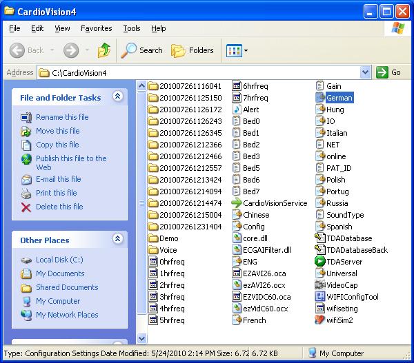
 inside the C:\CardioVision4 directory (see the first image on the next page). 2.")
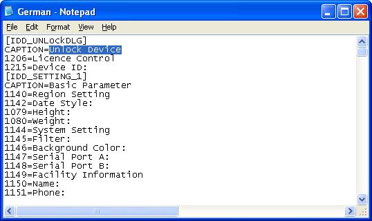
11 3.2 Verify all the settings are correct by clicking on System. You will be prompted for the password. When finished, click OK. Under Basic Parameter, you can set the Region Setting, System Setting, Facility Information, and Doctor Information. Under Alarm Parameter, you can set the Alarm Switch, Analysis Parameter, ST Analysis Parameter, Alarm Output, and Alarm Option. 3.3 Language Translation for CardioVision Server 1. To translate CardioVision into another language, first locate the.ini file for your desired language (eg. German.ini) inside the C:\CardioVision4 directory (see the first image on the next page). 2. Double-click the file to open it. If prompted, select Notepad, then click OK. 3. Translate the English words in this file after the equal signs (=) to the desired language (see the second image on the next page), then Save the file and Close it. 4. Select the Language from the Setting menu shown above (Step 3.2), click OK, and then restart the program. CardioVision will now be translated into your desired language. 10
12 11

13 3.4 Click on New on the main screen to begin recording a new patient. 3.5 Select the Channel for the patient based on the Bed setting saved to the recorder in Step 2.4. For example, if the Bed number was 2, then select CH2. Enter the rest of the information, including the name of the doctor or physician responsible for this patient, and click OK. Note: To set up a demo patient, click on the arrow next to WIFI Transmitter and select Demo. 12


 Clicking on the button will display the patient information screen, which will allow you to edit the")
14 3.6 If the recorder was set up properly, you should begin to see the real-time ECG in the row corresponding to the Bed/Channel specified earlier. If not, see Step 2.10 for troubleshooting tips. 3.7 The boxes in the left column contains patient information and 4 buttons: From top to bottom, you can see the patient s last name, room number, bed number, doctor s name, and start time of the recording. You can also see the battery indicator and heart rate. (See 3.5) Clicking on the button will display the patient information screen, which will allow you to edit the patient s demographic information as well as alarm options. 13


. Clicking on the button will allow you to")

15 Clicking on the arrow next to CH 1 will allow you to view the ECG on CH 2. Clicking on the button will allow you to toggle the alarm on/off. Clicking on the button will allow you to bring up the patient s ECG Strips saved from the Alerts, or view the complete Page Scan (See 3.8). Clicking on the button will allow you to change the amplitude of the real-time ECG. When there is an Alert, the box will flash red. Left-click the mouse anywhere in the box to turn off the alarm. 14

16 3.8 To increase or decrease the horizontal size of the patient data box, place the mouse cursor on the right edge of the box so that it changes to a resize cursor, and then drag it left or right. The re-size will always be done four at a time. In the example below, the size of the first four boxes was increased. 3.9 The ECG Strip display allows you to view the ECG strips corresponding to an alert for the selected patient. To change the strip, double-click on a different alert in the bottom left corner. Jump: Brings you to the event that is selected in the box to the left. Print: Prints the selected ECG strip. Pre Second: Moves the ECG strip back 1 second at a time. Next Second: Moves the ECG strip forward 1 second at a time. Pre Page: Moves the ECG strip back 8 seconds at a time. Next Page: Moves the ECG strip forward 8 seconds at a time. 15
17 The Page Scan option gives you an overview of the entire full disclosure ECG. The sidescrolling HR Trend box at the top allows quick review of all full disclosure ECG data. You can double-click a strip to zoom-in, which brings up the window above. You can also left click on the desired ECG strip in the Full Disclosure area, followed by a right-click, to bring up another menu, where you can select CH1, CH2, or Print 1-hour Full disclosure. Left-clicking anywhere in the HR Trend timeline in the top box will display the full disclosure for that time period below. 16
18 3.10 By right-clicking in the ECG area, you can change the ECG display for the corresponding patient: The above image is an example of the five different ECG display options: CH1 only CH2 only CH1 and CH2 CH1 and Full Disclosure 1 CH2 and Full Disclosure 2 Selecting Grid will toggle the ECG strip grid for all patients: 17

19 3.11 The boxes in the right column can be used to display various types of data. By default, it is set to Trend. By left-clicking on the blue arrow in the top-left corner of each box, you can change it to Two Box or Combo View. There are also green arrows you can click on in the top, center, or right area, to change the channel or scroll the ST baseline markers left/right. Use the Tab key to select the highlighted ST marker, and then use the keyboard arrow keys to place the ST baseline markers. In the example above, the first five beds are displaying Trend views, and the bottom three beds are displaying Two Box views. By right-clicking anywhere in the boxes, whether it is the Trend box or the left/right box in a Two Box view, you can select which type of data is being displayed. The Video Monitor option will bring up a live feed from the webcam, if there is one connected to the computer. Selecting Combo View for a patient will open a pop-up window displaying many pieces of information for the selected patient. This window can be moved around as needed. Only one Combo View window may be open at any time For Alarm Options and Trend Display, click on the button in the upper right corner. 18

20 3.13 Trend Display (To be shown on the 2 nd (right-side) monitor) Compare HR, VE, V-Run, ST, and Pause data. Double-click on areas of interest to bring up page scan and ECG strips. Lower portions of each box area can be scrolled by minute, hour or day to scan the data. For each corresponding patient on the 1 st (left-side) monitor, the Trend Display shows Heart Rate, V-Tach, ST, and Pause trends for up to 3 days. The purpose is to provide a quick and user-friendly method for immediate access to serious ECG abnormalities. A-Fib will usually display on HR Trend as an increase in Heart Rate with long green lines that indicate significant min and max HR changes for each minute. ST events will show the ST-level on a minute-to-minute trend basis for ST Elevations or ST depressions. V-Tach events will display as a yellow box in the HR Trend for the hour of the detected V- Tach. 19
21 Pause events will display as a yellow box in the ST Trend for the hour of the detected Pause. Point the arrow and do a double left-click to display the desired Page Scan (Full Disclosure) data. For HR Trend and ST Trend, click on the desired section of the timeline. For VE, V- Run, and Pauses, click on the colored boxes below the timeline of the indicated episodes. You may need to scroll the full disclosure data up and down in order to see the desired ECG data for the selected hours Alarm Alert Display From the main screen, move the mouse to the lower-left Alarm Alert area to expand it. Double-click on the desired alarm to bring up the ECG strip menu and the alarm history list which you can scroll through for other ECG strips. To delete individual alarms, left-click on the desired alarm and click the Delete button. To delete all alarms in the alarm menu, click the Delete All button. Next to Bed: is a drop-down menu where you can filter the alarms by bed number and only view alarms for a particular bed. 20

.")
22 3.15 From the main screen, click on the Patient List icon to bring up the current and past patient database. You can select a past patient (one without the monitor icon to the left) and click on Access Patient, then Page Scan to bring up the page scan of a prior patient (See 3.9). If you notice any errors in the patient list, click the Sync Database button to synchronize the patient list database. 21


23 4. Using CardioScan for Holter analysis of CardioVision patients 4.1 To run CardioScan while the CardioVision Server is running, click on the Holter icon. If the CardioScan window does not appear, it is still running in the background. Simply minimize CardioVision Server and it will appear. If the CardioVision Server is not running, you can double-click on the CardioScan icon on the desktop. Lead Placement: View lead placement diagrams. Enroll: This function is for Holter only. New Patient: This function is for Holter only. Prior Holter: Opens up the patient database. System Setting: Modify system settings. Help: System information, Learning center, CE information. Exit: Closes the Holter program. Sync Data: Synchronizes the patient data for file maintenance purposes. 4.2 To view previous and current patients or to import a patient currently being monitored in CardioVision Server, click on Prior Holter. 22


24 4.3 To import a patient into the Holter CardioScan function from CardioVision Server, click on Online Holter in the bottom right corner. A new window will appear. 4.4 You will see a list of all the patients being monitored that have not been imported into CardioScan yet. Any finished recordings that have not been imported during the recording will also show up here. Select the patient you wish you import by left-clicking it, and click Import. To import a group of patients, left-click on the first patient, hold down the Ctrl key on the keyboard, and select the additional patients, then click Import. When finished, click Close. These patients will now appear in your Prior Holter menu. 4.5 To update a patient currently being monitored with the ECG data since the last review, simply open that patient file and you will be prompted to update the patient data. Note: Please see the CardioScan Premier manual for further operation instructions. 23


25 5. CardioVision PDA Software 5.1 To use the CardioVision PDA software, copy the contents of the PDA folder on the CardioVision CD (see 1.1) to an SD card. 5.2 Insert the SD card into the PDA, click on Start, then File Explorer. Locate the files which were copied in step Double click on CardioMessager.exe to start the program. Enter the IP address of the CardioVision Server into the box (this is the same as the Server IP in Step 2.5), and click Connect. 24


26 5.4 The Event Log: Connect / Disconnect button Event log View the ECG strip of the selected event Clear the event log List of patients being Monitored View Mode: Back to the Event Log Zoom out Patient data: Recorder CH#, Time, Name, Room, Bed, Event Scroll the ECG strip 25


27 Clearing the Event Log: To clear the Event Log, click on the Clear button, and then confirm by clicking Yes. Monitoring Mode: Select a patient being monitored from the list and click on Accss. This will bring up the real-time ECG of the selected patient. Click ok to return to the previous screen. 26
 is for Real-Time ECG monitoring, and Screen Display # 2 (right side) is for Holter ECG, large ECG strips, Full Disclosure, Trend Display, etc. 3.")
28 6.0 Detailed Operational Features of CardioVision 6.1 CardioVision 8-Patient Display: 1. Use two (2) separate monitors with each CardioVision (CV) system. 2. Screen Display # 1 (left side) is for Real-Time ECG monitoring, and Screen Display # 2 (right side) is for Holter ECG, large ECG strips, Full Disclosure, Trend Display, etc. 3. Holter ECG editing can be done at either the CV central station, or remotely from the Holter lab in another section of the hospital. 4. Cardiologists can access the patient data from their office or home. 5. The CV computer automatically sends Alarm and Real-Time ECG to PDAs so that the nurses or doctors can see the data without being at the central station. 6. Each minute the ECG data for all patients is formatted for Holter ECG analysis and processing. 7. Simultaneously the CV system is a Holter system and a Wireless ECG patient monitoring system. 27

29 6.2 Data Layout of Main Display of CardioVision: 1. The ECG display can be a 1-Lead display, a 2-Lead display, or a combination of 1-Lead with a Full Disclosure. Place the arrow on the ECG display area for any patient, and right mouse-click. 2. Patient and Physician information is at the far left. Patient name is Test. Click on the icon to the right of patient name in order to enter Patient and Physician data. After typing in the Patient and Physician data, click on the OK icon at the bottom of the pop-up window. 3. The Heart Rate is continuously displayed to the right of the Patient data. 4. Above the Heart Rate, you can select the dominant ECG lead for assisting analysis. 5. You can adjust the horizontal length of this Patient data box by a point and drag on the right side border (just to the right of the Heart Rate number). 6. The red color in the Patient data box is when the patient has an Alert or electrode disconnect. 7. The right side of the ECG display is for real-time analysis of ST Segment, QTc, Pauses, Tachy, etc. 8. The lower left of the screen display is for the display of the Alerts for the patients monitored. 28

30 6.3 Viewing ECG Strips of Interest: 1. This is the screen display for a real-time ECG. You can do a single click on one of the Alerts at the bottom left of the screen display, and get an immediate real-time ECG that is displayed on Screen Display # 2, so that it does interfere with the on-going real-time ECG display of all 8- patients. 2. In the above ECG strip example, the ECG from the Alerts section is shown with the blue shading. 3. This ECG can be scrolled backwards and forwards to find the exact ECG that you want to print. 4. Each individual ECG beat has already been analyzed for a normal, arrhythmia, or ST category. 5. You can see the V markings at the top of the ECG strip the shows that these two beats were Ventricular (V) ectopic beats. The N is for Normal beat. 6. For each R-R interval, you see the Heart Rate and the mille-seconds from beat to beat. 7. You can also access ECG strips by clicking on the icon that is the third icon past the patient name. A left mouse click will ask you to select ECG Strip or PageScan (Full Disclosure). 8. It is recommended that you first select the PageScan mode (see next page), and from PageScan go to the selection of the desired ECG Strip. 9. The bottom of the ECG strip display allows you to move to various time locations that are pre and post the displayed ECG. 10. There is a print icon at the bottom of this display that will allow you to get an immediate ECG print. 11. You can exit the ECG strip display by a left mouse click on the Close icon 12. Note: All ECG data can be later reviewed in the Holter mode in this same CardioVision system. Simultaneously, Screen Display #1 is Wireless Patient Monitoring, and # 2 is full-function Holter. 29

31 6.4 Advanced-Auto-Analyzed Full Disclosure: 1. The above is the PageScan display. It is the instantaneous Full Disclosure display of all of the patient s ECG data. This could be multiple days of monitoring, and it is all right here. 2. At the top of the display is the Heart Rate Trend for the minutes, hours, and days of monitoring. 3. The Full Disclosure ECG is in the middle section, and the enlarged ECG is at the bottom. 4. If you want to see the Full Disclosure ECG for the current minute of data, it is here. The ECG beats are transferred to this Full Disclosure mode on a single beat-to-beat basis. 5. At the top of the ECG display you see a large sine-wave display. It is displayed if there is a technical malfunction; such as an electrode disconnected, battery failure, etc. 6. Each horizontal line in Full Disclosure is one-minute of ECG data. 7. You can see a green rectangular box in the lower right section of Full Disclosure. That ECG data in the green box is what is displayed in the enlarged ECG strip at the bottom of this display. 8. If you place the mouse arrow in a different area of interest in Full Disclosure, a single left click will display ECG in the enlarged ECG, and a double left click will bring you to the ECG print menu. 30

32 VE Beat Analysis Ventricular Runs (Tachy) SVE Beat Analysis Supraventricular Runs (Tachy) Pauses QT and QTc Analysis R-R Histogram Poincare Plots Normal to VE Histogram Normal to SVE Histogram HRV Total Power HRV VLF Power HRV Low/High Freq. Ratio HRV SDNN Time Domain HRV pnn50 HRV rmssd 6.5 AUTO-ECG Analysis for each Patient 1. To the right side of each patient s real-time ECG are ECG analysis boxes. 2. As shown above, you have sixteen (16) different types of analysis to view. 3. This 16-analysis view can be seen for any patient at any time. 4. You access this data by clicking on the word Combo. 5. See other part of manual for accessing and selecting a one or two box display of selected analysis at the right side of each patient s display of real-time ECG. 31
33 6.6 ECG ANALYSIS at far right of screen display: This screen display shows the viewing of the sixteen (16) analysis functions that occur each minute during the real-time Wireless monitoring. 1. ST Segment Analysis or Heart Rate Trends are available on an on-going basis for each patient. 2. You can select two boxes or one box for analysis display in the normal monitoring mode. 3. The bottom two patients are showing the ST Analysis display. At all times the amount of ST Depression or Elevation is numerically displayed. Each minute gets a green or red vertical line. The red vertical lines are the ST Depressions exceeding ST Level limit. For each patient in this ST box analysis display, you can set the markers for PR baseline, J-point, and ST-point. You can also select either Delta ST Analysis or Absolute ST Analysis. 4. No real-time ECG monitoring system has anything close to the ECG analysis capability of this Wi-Fi Wireless ECG monitoring system. And then you get the on-going full-functioning CardioScan Holter ECG system and reporting for each patient. At the end of each minute, the ECG data is formatted for the Holter ECG capability. In an emergency, the cardiologist from his/her home PC can immediately access the Holter for the past 1 or 2 hours, and make a good decision for patient treatment. 32

34 6.7 PDA for Remote Alerts and Bedside Monitoring 1. Alerts for patients are stored in the lower left section of this display. 2. If the nurse is not at the central station, her PDA will be automatically and instantly activated by the central CV PC, and the ECG Alert strip will be seen on her PDA display. 3. The PDA display can also be used as a bedside monitor for any patient by the nurse or doctor. 4. Multiple PDAs can be operating simultaneously. 5. From this lower left display, you can access the real time ECG of any Alert by doing a double left-click on the desired ECG. 6. You can delete a single patient Alert or all patient Alerts by clicking on the appropriate icons to the right side of the Alert data section. 7. Pause and V-Tach Alerts cannot be de-activated. All other Alerts are optional. 8. Brady and Tachy Alerts are set at any desired heart rates for each patient individually. 33
 are shown on right side monitor. 4. The Holter is performed on the right side monitor. 5.")
35 6.8 Dual Screen Displays for CardioVision 1. The above shows two (2) independent display monitors. 2. The Wi-Fi Wireless Real-Time ECG is shown for each patient on the left side monitor, 3. Other real-time displays (such as enlarged ECG strips, Full Disclosure, etc) are shown on right side monitor. 4. The Holter is performed on the right side monitor. 5. No screen display data is to block out the patient s real-time ECG data. 6. The Wi-Fi transmitter keeps track of its battery power, and there is a continuous display in the left side Patient data box that shows the battery status. 7. The Wi-Fi transmitter also acts as a Holter recorder. If desired, the patient s stored ECG data can be transferred from the Wi-Fi transmitter to the Holter PC in the same manner as a regular Holter monitoring. 8. The purpose of this is to provide an insurance back-up; for example, when the patient is removed to another building for a special procedure, or if there was a power failure in the CV system, etc. 9. With our CV-Holter network, the Holter data can be remotely edited by Holter experts in the Holter lab that may be on the opposite side of the hospital. 10. All of the Holter functions that are in our CardioScan software are included in the Holter portion of the CV system. 11. It is now OBSOLETE to do traditional Holter ECG monitoring inside the hospital. Why wait for one or two days to see the result of the Holter monitoring. The Wi-Fi CV system is the BEST mode for performing Holter testing. While you are doing the Holter, all of the same data is available in the most sophisticated real-time ECG central station system. If the Sustained V- Tach or 5-second Pause occurred 5-hours into the Holter monitoring, everyone is alerted at that time and the Sustained V-Tach, etc. is known at that time. Why waste everyone s time, energy, and money by waiting a couple of days to find out what happened. 34
36 6.8a Use of second display monitor for Trends of Real-Time ECG patients 1. Trends can be seen and accessed for 3-days of monitoring for each patient. 2. The Trends are specific to Heart Rate, A-Fib, V-Tachs, VE Beats, ST Depression, and Pauses. 3. The trends for each patient are adjacent to the patient real-time ECG data on the left side monitor. 4. To display Trends, click on Trends at the top right of the main display monitor. 5. Each patient in Trends has a slide-bar to move the trend data through the 3-day time period. 6. A visual quick-look at the Heart Rate trend will usually reveal if an A-Fib episode occurred. You would see a jump in the HR trend along with the vertical lines be longer, indicating that the min and max heart rate range was significantly increased. 7. During 1-hour periods of V-Tach or multiple VE beats, a colored box will be displayed below the Heart Rate trend for each patient. 8. During ST Depression, the ST trend on the right side will show the amount of ST Depression. You can select either Delta ST or Absolute ST as the method for detecting ST changes. 9. Below the ST trend are the colored boxes showing Pause beats. 10. Use the mouse to click on the trend time periods of interest. 11. Upon clicking on the trend time period, the Page Scan Full Disclosure will appear. You can use the slide bar on the right side to quickly view the entire 1-hour time period. Upon viewing the ECG of interest, point the mouse area at the ECG event, and do a double left click to view the enlarged ECG. 6.8b Use of the second monitor for Holter ECG 1. At any time the second display monitor can be used for the Holter viewing and editing of the ECG data. 2. When you click on the On-Line Holter function, the second monitor becomes an independent Holter ECG system for the same patients that you are viewing on the real-time ECG display on the left side. 3. At the end of each minute of the real-time ECG monitoring, the 100% ECG data for each patient is transferred into that patient s Holter ECG file. Thus, the single Wi-Fi ECG transmitter is fulfilling the functions of both the real-time ECG and the Holter ECG. 4. The Holter data is processed in the same manner as the CardioScan Holter ECG system. 5. As a practical manner for most hospitals, the Holter ECG data can be remotely accessed from the Holter lab in the Cardiology Department; thus allowing the Holter to be edited by Holter ECG experts. 35

37 6.9 Settings Menu for Language Translations, Filters, etc. 1. At the bottom of the 8-Patient real-time ECG display, there is an icon for System Setting. 2. Click on this icon to bring up the above pop-up window. 3. The language can be translated for you country s needs. 4. We will give you a Translation Language Package. Translate and return it to DMS. 5. Type in the desired data for each field. 6. It is recommended to select the Filter in the ON position. 7. Before closing, click on the Alarm Parameter tab at the top. This will take you to the next pop-up window for analysis settings. 36

38 6.10 Settings Menu for Analysis 1. Note that the VRun and Pause alerts cannot be de-activated. 2. Heart Rate, ST, and SupraVentricular Runs alerts are optional. 3. A check-mark will activate Heart Rate, ST, and SupraVentricuar alerts. 4. There is a SVE Prematurity field. 5. For non Atrial Fib patients, the 25% setting is recommended. 6. For Atrial Fib patients, the 20% setting is recommended. 7. For ST Analysis, you can select Absolute or Delta. This selection varies from country-tocountry. The Delta setting is the most common setting. 8. Absolute ST is the ST Depression or Elevation that is measured from the patient s PR baseline level. 9. Delta ST calculates the ST Level that occurs most often in 24-hours, and uses that ST Level as that individual patient s zero baseline. The ST Depression or Elevation is then measured as the amount of ST change from the patient s most common ST Level. 10. Alarm Output: PDA use is most highly recommended. Select your desired sound options. 37
39 6.11 Different Analysis for Different Patients 1. The top six (6) patients are shown with ST or Heart Rate Trends in the analysis box at the far right side of each patient s real-time ECG. 2. The bottom two (2) patients show the two (2) box analysis display. 3. Click on the top left corner of the analysis box to bring up an analysis selection. 4. The very top option of the selections is a VIDEO MONITOR option. 5. If you place a low cost, off-the-shelf video camera in the patient s room, you can view at the central station the patient s presence in the bed. The video display is shown in the analysis box for the selected patient. 6. For an Analysis trend in the Analysis box, click on the desired Analysis. 38

40 6.12 Selection of Desired Analysis for each Patient 1. You can select either the one Analysis box mode or the two Analysis box mode. 2. When you select the two Analysis box mode, you get the above pop-up window. 3. This will allow you to click on the two sets of Analysis that you want displayed. 4. The bottom two patients show the two Analysis box mode. 5. There are eight (8) different Heart Rate Variability (HRV) analysis modes. 6. Some of the HRV analysis modes show both the HRV analysis for the total time and also for the prior 5-minute time period. 7. All of the analysis is backed-up by the CardioScan Holter analysis, such as: ATRIAL FIBRILLATION, T-WAVE ALTERNANS, HRV-Time Domain and Frequency, QTc by Time and ms, DELTA ST SEGMENT. 39

41 6.13 Auto Holter backs up all the CardioVision real-time ECG 1. The CV system includes a separate CardioScan Holter ECG system. 2. The CV system can be considered to be a hospital Holter ECG system that also does the most sophisticated Wireless real-time ECG hospital monitoring at the same time as doing the Holter. 3. The CV system can also be considered a sophisticated Wi-Fi wireless real-time ECG hospital monitoring system that is backed-up minute-by-minute by the CardioScan Holter ECG system. 4. While being used as a hospital Holter ECG system, this is the only Holter system with the advanced technology that also provides beat-to-beat display and analysis at a central station. 5. The results of the Holter analysis of just a few hours, or up to 7-days, can be immediately accessed by the concerned cardiologist at any time from the PC in the cardiologist s office or home. 6. For a small hospital or clinic without a cardiologist, the cardiologist can always have remote access. 40

42 6.14 The Holter ECG Function: The Holter data is presented in the CV system in the same manner as the PRIOR menu in the Holter CardioScan system. 1. For the first transfer from the CV real-time data, click on the Online Holter icon at the lower right of the above menu. 2. This will start the process of Importing the patient ECG file into the format that is the same as the Holter CardioScan system. 3. There is no limit to the number of hours or days that the patient can be monitored in real-time or in the Holter mode. 4. When you click on the Online Holter icon, you will see a list of patients that have not been IMPORTED into the CardioVision Client (Holter CardioScan). 5. Click on the patient you wish to Import, and then click on the IMPORT icon. Close to finish. 6. To update a patient currently being monitored with the new and additional Holter ECG data, simply open the patient file and you will be prompted to update the patient Holter ECG data. 41

43 6.15 The Most Sophisticated Holter ECG System Available 1. When accessing the patient s Holter data, the patient may have multiple days of Holter ECG recordings. 2. When accessing the patient s Holter data, a pop-up window will be displayed in the Patient data box in the real-time CV ECG display. This pop-up window allows you to select the day of Holter ECG that you want to access. 3. Notice: If you use a one screen PC or Notebook, you may cover up the left side monitor with the right side PRIOR menu. This can prevent you from accessing the Holter day selection, and block you from proceeding. This is one of many reasons for always using a two (2) monitor display for the CardioVision system. 4. When you click on the desired day for the Holter ECG data, the right side monitor will take you into the standard Holter ECG program for editing, reporting, and storing. 5. All functions of the Holter CardioScan system are now available to you. 6. All CV systems include one (1) CV security key for the central station PC. There is also a security key for the CardioScan back-up PC for the Holter ECG lab. The Holter CardioScan PC in the Holter lab acts as both (1) the remote Holter editor for the CV central station PC, and (2) the out-patient Holter ECG capability. This out-patient Holter capability includes the Satellite Easy technology that allows the Holter ECG from the patient s home to be transmitted each 24- hours. For the first time, with this capability, the cardiologist will know exactly how many days to perform an out-patient Holter ECG test. The out-patient Holter monitoring can be done from 1 to 30 days with the single Holter recorder. 42
6. Cloud Database retrieval of ECG reports by Mobile Phone, Tablet, or Notebook.
 CardioScan 77a, with Build Date 20141117 v.78a This Section A is for Holter customers who are updating their CardioScan Software. 1. Additional ECG Analysis capabilities. 2. New Editing Process. 3. Respiration
OPERATOR S MANUAL FOR DMS 300-4A HOLTER ECG RECORDER
 OPERATOR S MANUAL FOR DMS 300-4A HOLTER ECG RECORDER WARNING Only a physician can order a Holter ECG test. WARNING Only the ordering physician can decide on the application technique used for affixing
Galix WinTer. Holter Analyzer
 Galix WinTer Holter Analyzer User s Manual 2555 Collins Avenue, Suite C-5, Miami Beach, FL 33140, U.S.A. Tel.: (305) 534-5905 Fax: (305) 534-8222 INDEX 1 INTRODUCTION...4 1.1 CORRECT ELECTRODE PLACEMENT...4
EOS 80D (W) Wireless Function Instruction Manual ENGLISH INSTRUCTION MANUAL
 Wireless Function Instruction Manual ENGLISH INSTRUCTION MANUAL") EOS 80D (W) Wireless Function Instruction Manual ENGLISH INSTRUCTION MANUAL Introduction What You Can Do Using the Wireless Functions This camera s wireless functions let you perform a range of tasks wirelessly,
EOS 80D (W) Wireless Function Instruction Manual ENGLISH INSTRUCTION MANUAL Introduction What You Can Do Using the Wireless Functions This camera s wireless functions let you perform a range of tasks wirelessly,
Product description: sp_walk400h_cardiolinespa_07_eng1.doc 1/2
 walk400h walk400h walk400h is a latest-generation holter recorder able to acquire and memorise from 3 to 12 ECG channels, compatible with the holter reader software CARDIOLINE, for details of which see
ECG HOLTER INtUItIVe USeR INteRFAce Interactive Graphs Interactive Histograms navigation by extremes Fully Customizable R E LT O H CG E
 ECG HOLTER new 2 ecg Holter NEW POSSIBILITIES IN HOLTER DIAGNOSTICS btl ecg Holter The BTL ECG Holter satisfies the needs of the most demanding ECG experts, while at the same time making their work both
Context-Aware Planning and Verification
 7 CHAPTER This chapter describes a number of tools and configurations that can be used to enhance the location accuracy of elements (clients, tags, rogue clients, and rogue access points) within an indoor
9/2/2013 Excellent ID. Operational Manual eskan SADL handheld scanner
 9/2/2013 Excellent ID Operational Manual eskan SADL handheld scanner Thank You! We are grateful you chose Excellent ID for your SADL scanner needs. We believe this easy-to-use scanner will provide dependable
AirScope Spectrum Analyzer User s Manual
 AirScope Spectrum Analyzer Manual Revision 1.0 October 2017 ESTeem Industrial Wireless Solutions Author: Date: Name: Eric P. Marske Title: Product Manager Approved by: Date: Name: Michael Eller Title:
FLIR Tools for PC 7/21/2016
 FLIR Tools for PC 7/21/2016 1 2 Tools+ is an upgrade that adds the ability to create Microsoft Word templates and reports, create radiometric panorama images, and record sequences from compatible USB and
WEB I/O. Wireless On/Off Control USER MANUAL
 Wireless On/Off Control Technical Support: Email: support@encomwireless.com Toll Free: 1 800 617 3487 Worldwide: (403) 230 1122 Fax: (403) 276 9575 Web: www.encomwireless.com Warnings and Precautions Warnings
Nikon View DX for Macintosh
 Contents Browser Software for Nikon D1 Digital Cameras Nikon View DX for Macintosh Reference Manual Overview Setting up the Camera as a Drive Mounting the Camera Camera Drive Settings Unmounting the Camera
Location Planning and Verification
 7 CHAPTER This chapter describes addresses a number of tools and configurations that can be used to enhance location accuracy of elements (clients, tags, rogue clients, and rogue access points) within
Endurance R/C Wi-Fi Servo Controller 2 Instructions
 Endurance R/C Wi-Fi Servo Controller 2 Instructions The Endurance R/C Wi-Fi Servo Controller 2 allows you to control up to eight hobby servos, R/C relays, light controllers and more, across the internet
SKF TKTI. Thermal Camera Software. Instructions for use
 SKF TKTI Thermal Camera Software Instructions for use Table of contents 1. Introduction...4 1.1 Installing and starting the Software... 5 2. Usage Notes...6 3. Image Properties...7 3.1 Loading images
WPE 48N USER MANUAL Version1.1
 Version1.1 Security instructions 1. Read this manual carefully. 2. Follow all instructions and warnings. 3. Only use accessories specified by WORK PRO. 4. Follow the safety instructions of your country.
Warehouse Instruction Guide
 Warehouse Instruction Guide Review Equipment & Supplies page 2 Set-Up Access Point page 6 Register Scanners page 8 Place Fixture Stickers/Enter Ranges page 10 Scanning Basics and Additional Keyboard Functions
Manual. ios App. Ver2.2. v Mall Drive, Commack, NY (P) (F)
 (F)") Manual Ver2.2 ios App v1.6 73 Mall Drive, Commack, NY 11725 631-864-1000 (P) 631-543-8900 (F) www.accu-scope.com info@accu-scope.com Contents CHAPTER 1: SYSTEM REQUIREMENT & SOFTWARE -------------------------------------
Manual Ver2.2 ios App v1.6 73 Mall Drive, Commack, NY 11725 631-864-1000 (P) 631-543-8900 (F) www.accu-scope.com info@accu-scope.com Contents CHAPTER 1: SYSTEM REQUIREMENT & SOFTWARE -------------------------------------
LincView OPC USER GUIDE. Enhanced Diagnostics Utility INDUSTRIAL DATA COMMUNICATIONS
 USER GUIDE INDUSTRIAL DATA COMMUNICATIONS LincView OPC Enhanced Diagnostics Utility It is essential that all instructions contained in the User Guide are followed precisely to ensure proper operation of
CamFi TM. CamFi User Guide. CamFi Remote Camera Controller. CamFi Limited Copyright 2015 CamFi. All Rights Reserved.
 CamFi TM CamFi User Guide CamFi Remote Camera Controller CamFi Limited Copyright 2015 CamFi. All Rights Reserved. Contents Chapter 1:CamFi at glance 1 Packaging List 1 CamFi Overview 1 Chapter 2:Getting
QAM Snare Navigator Quick Set-up Guide- Wi-Fi version
 QAM Snare Navigator Quick Set-up Guide- Wi-Fi version v1.0 3/19/12 This document provides an overview of what a technician needs to do to set up and configure a QAM Snare Navigator Wi-Fi version for leakage
Progeny Imaging. User Guide V x and Higher. Part Number: ECN: P1808 REV. F
 Progeny Imaging User Guide V. 1.6.0.x and Higher Part Number: 00-02-1598 ECN: P1808 REV. F Contents 1 About This Manual... 5 How to Use this Guide... 5 Text Conventions... 5 Getting Assistance... 6 2 Overview...
Introduction to: Microsoft Photo Story 3. for Windows. Brevard County, Florida
 Introduction to: Microsoft Photo Story 3 for Windows Brevard County, Florida 1 Table of Contents Introduction... 3 Downloading Photo Story 3... 4 Adding Pictures to Your PC... 7 Launching Photo Story 3...
Progeny Imaging Veterinary
 Progeny Imaging Veterinary User Guide V1.14 and higher 00-02-1605 Rev. K1 ECN: ECO052875 Revision Date: 5/17/2017 Contents 1. About This Manual... 6 How to Use this Guide... 6 Text Conventions... 6 Getting
Generations Automatic Stand-Alone Lace By Bernie Griffith Generations Software
 We are going to create an open Italian lace. Generations software products provide advanced image processing features allowing for the creation of stand-alone lace with just a few simple techniques. A
Scanner Utility for Microsoft Windows Version 9.6. User's Guide
 P3PC-E892-03EN Scanner Utility for Microsoft Windows Version 9.6 User's Guide For Use with Microsoft Windows 98, Windows Me, Windows 2000 and Windows XP Introduction Thank you for purchasing the "Scanner
Getting Started Guide
 SOLIDWORKS Getting Started Guide SOLIDWORKS Electrical FIRST Robotics Edition Alexander Ouellet 1/2/2015 Table of Contents INTRODUCTION... 1 What is SOLIDWORKS Electrical?... Error! Bookmark not defined.
ADMS-847 Programming Software for the Yaesu FT-847
 for the Yaesu FT-847 Memory Types Memories Limit Memories VFO A VFO B Home Satellite Memories One Touch Memory Channel Functions Transmit Frequency Offset Frequency Offset Direction CTCSS DCS Skip The
INSTRUCTION MANUAL IP REMOTE CONTROL SOFTWARE RS-BA1
 INSTRUCTION MANUAL IP REMOTE CONTROL SOFTWARE RS-BA FOREWORD Thank you for purchasing the RS-BA. The RS-BA is designed to remotely control an Icom radio through a network. This instruction manual contains
TT-208. User s Manual. 300Mps 5.8 GHz. IP Camera Wireless Transmission Kit
 TT-208 300Mps 5.8 GHz IP Camera Wireless Transmission Kit User s Manual V1.0 02 / 2014 Welcome Thank you for purchasing the TT-208 Wireless Transmission Kit for IP Cameras. This user s manual is designed
ArbStudio Triggers. Using Both Input & Output Trigger With ArbStudio APPLICATION BRIEF LAB912
 ArbStudio Triggers Using Both Input & Output Trigger With ArbStudio APPLICATION BRIEF LAB912 January 26, 2012 Summary ArbStudio has provision for outputting triggers synchronous with the output waveforms
23070 / Digital Camera Owner s Manual
 23070 / 23072 Digital Camera Owner s Manual 2007 Sakar International, Inc. All rights reserved. 2007 Crayola Windows and the Windows logo are registered trademarks of Microsoft Corporation. All other trademarks
Helping you improve patient care. Welch Allyn Holter Systems
 Helping you improve patient care. Welch Allyn Holter Systems Welch Allyn Holter Systems User-friendly, powerful systems that are tailored to meet your needs. Welch Allyn Holter Systems feature easy-to-use
Kodiak Corporate Administration Tool
 AT&T Business Mobility Kodiak Corporate Administration Tool User Guide Release 8.3 Table of Contents Introduction and Key Features 2 Getting Started 2 Navigate the Corporate Administration Tool 2 Manage
Magic Wand Portable Scanner with Auto-Feed Dock. PDSDK-ST470-VP-BX2 User Manual
 Magic Wand Portable Scanner with Auto-Feed Dock PDSDK-ST470-VP-BX2 User Manual Table of Contents 1. KEY FEATURES... 2 2. FUNCTIONAL PARTS... 2 3. EXPLANATION OF THE STATUS ICONS... 4 4. GETTING STARTED...
Figure 1 The Raith 150 TWO
 RAITH 150 TWO SOP Figure 1 The Raith 150 TWO LOCATION: Raith 150 TWO room, Lithography area, NanoFab PRIMARY TRAINER: SECONDARY TRAINER: 1. OVERVIEW The Raith 150 TWO is an ultra high resolution, low voltage
User Guide. Version 1.2. Copyright Favor Software. Revised:
 User Guide Version 1.2 Copyright 2009-2010 Favor Software Revised: 2010.05.18 Table of Contents Introduction...4 Installation on Windows...5 Installation on Macintosh...6 Registering Intwined Pattern Studio...7
User Guide. Version 1.4. Copyright Favor Software. Revised:
 User Guide Version 1.4 Copyright 2009-2012 Favor Software Revised: 2012.02.06 Table of Contents Introduction... 4 Installation on Windows... 5 Installation on Macintosh... 6 Registering Intwined Pattern
House Design Tutorial
 Chapter 2: House Design Tutorial This House Design Tutorial shows you how to get started on a design project. The tutorials that follow continue with the same plan. When you are finished, you will have
Altair Avionics Corporation Monitor Link Program
 Altair Avionics Corporation Monitor Link Program Altair Avionics Monitor Link Program MLP User s Guide By Tyler Dawbin Approved By: Doug Thompson, General Manager David L. Fetherston, Manager Engineering
Faculty Lecture Capture Guide
 Faculty Lecture Capture Guide If you have never used Panopto before, follow this first part. Log into your Blackboard Account and open the course you wish to capture: Open your Course Management Control
MANUAL. Textron Motors Diagnostic Tool. This manual is valid for the following Textron Motors Diagnostic Tool:
 MANUAL Textron Motors Diagnostic Tool This manual is valid for the following Textron Motors Diagnostic Tool: 0507 TD0507_HB Rev F 6..05 en_english Read the manual before performing the task on the engine.
The ideal K-12 science microscope solution. User Guide. for use with the Nova5000
 The ideal K-12 science microscope solution User Guide for use with the Nova5000 NovaScope User Guide Information in this document is subject to change without notice. 2009 Fourier Systems Ltd. All rights
House Design Tutorial
 House Design Tutorial This House Design Tutorial shows you how to get started on a design project. The tutorials that follow continue with the same plan. When you are finished, you will have created a
Scan Sat Network S.L.
 Scan Sat Network S.L. IPTV Issue Solver Guide No Signal on the screen with IPTV. My IPTV channels are stopping. My Radio is not working I don t get any sound on my channels No Signal on the screen with
About the DSR Dropout, Surge, Ripple Simulator and AC/DC Voltage Source
 About the DSR 100-15 Dropout, Surge, Ripple Simulator and AC/DC Voltage Source Congratulations on your purchase of a DSR 100-15 AE Techron dropout, surge, ripple simulator and AC/DC voltage source. The
User Guide / Rules (v1.6)
") BLACKJACK MULTI HAND User Guide / Rules (v1.6) 1. OVERVIEW You play our Blackjack game against a dealer. The dealer has eight decks of cards, all mixed together. The purpose of Blackjack is to have a hand
BLACKJACK MULTI HAND User Guide / Rules (v1.6) 1. OVERVIEW You play our Blackjack game against a dealer. The dealer has eight decks of cards, all mixed together. The purpose of Blackjack is to have a hand
Timekeeper/Statistical tool for Basketball Sponsor: Prof. Wayne Dyksen & MSU Basketball Team Spring User Guide
 Timekeeper/Statistical tool for Basketball Sponsor: Prof. Wayne Dyksen & MSU Basketball Team Spring 2004 User Guide Team 2 Edward Bangs Bryan Berry Chris Damour Kim Monteith Jonathan Szostak 1 Table of
User Guide Wide Format Scanners. Model: SD One MF
 User Guide Wide Format Scanners Model: SD One MF July 2016 About this Guide 2 Contents Contents... 2 About this Guide... 4 Overview of the Scanner... 5 Scanner front view... 5 Scanner rear view... 6 Touch
Table of Contents. Chapter 1: Software Installation...1. Chapter 2: Running the Software II. Daily Practical Operation...10
 Product Manual Table of Contents Chapter 1: Software Installation.................................1 Chapter 2: Running the Software............................... 2 I. The Initial Defining in Lock Management
A Step-by-step Guide to Installing and Configuring your Vonets VAP11G Wifi Bridge
 A Step-by-step Guide to Installing and Configuring your Vonets VAP11G Wifi Bridge (c) 2011 Zarar Iqbal D0033 21/6/2011 About this guide T he main aim of this guide is to guide you through putting your
Photoshop CS2. Step by Step Instructions Using Layers. Adobe. About Layers:
 About Layers: Layers allow you to work on one element of an image without disturbing the others. Think of layers as sheets of acetate stacked one on top of the other. You can see through transparent areas
Using the Desktop Recorder
 Mediasite Using the Desktop Recorder Instructional Media publication: 09-Students 9/8/06 Introduction The new Desktop Recorder from Mediasite allows HCC users to record content on their computer desktop
House Design Tutorial
 Chapter 2: House Design Tutorial This House Design Tutorial shows you how to get started on a design project. The tutorials that follow continue with the same plan. When we are finished, we will have created
Case Air Wireless TETHERING AND CAMERA CONTROL SYSTEM
 Case Air Wireless TETHERING AND CAMERA CONTROL SYSTEM PRODUCT MANUAL CAWTS03 v3.14 Windows ABOUT CASE AIR The Case Air Wireless Tethering System connects and transfers images instantly from your camera
"Terminal RG-1000" Customer Programming Software. User Guide. August 2016 R4.3
 "Terminal RG-1000" Customer Programming Software User Guide August 2016 R4.3 Table of Contents Table of Contents Introduction 2 3 1.1 Software installation 3 1.2 Connecting the RG-1000 GATEWAYs to the
WSM WIRELESS SYSTEMS MANAGER SENNHEISER WSM. Instruction manual
 WSM WIRELESS SYSTEMS MANAGER SENNHEISER WSM Instruction manual Contents Contents Important information regarding this instruction manual... 3 For your safety... 3 Capabilities of the WSM... 4 System requirements...
UCP-Config Program Version: 3.28 HG A
 Program Description HG 76342-A UCP-Config Program Version: 3.28 HG 76342-A English, Revision 01 Dev. by: C.M. Date: 28.01.2014 Author(s): RAD Götting KG, Celler Str. 5, D-31275 Lehrte - Röddensen (Germany),
1 ImageBrowser Software User Guide 5.1
 1 ImageBrowser Software User Guide 5.1 Table of Contents (1/2) Chapter 1 What is ImageBrowser? Chapter 2 What Can ImageBrowser Do?... 5 Guide to the ImageBrowser Windows... 6 Downloading and Printing Images
Learning Guide. ASR Automated Systems Research Inc. # Douglas Crescent, Langley, BC. V3A 4B6. Fax:
 Learning Guide ASR Automated Systems Research Inc. #1 20461 Douglas Crescent, Langley, BC. V3A 4B6 Toll free: 1-800-818-2051 e-mail: support@asrsoft.com Fax: 604-539-1334 www.asrsoft.com Copyright 1991-2013
Chanalyzer by MetaGeek USER GUIDE page 1
 Chanalyzer 5 Chanalyzer by MetaGeek USER GUIDE page 1 Chanalyzer 5 spectrum analysis software Table of Contents Introduction What is Wi-Spy? What is Chanalyzer? Installation Choose a Wireless Network Interface
House Design Tutorial
 Chapter 2: House Design Tutorial This House Design Tutorial shows you how to get started on a design project. The tutorials that follow continue with the same plan. When you are finished, you will have
Getting Started. with Easy Blue Print
 Getting Started with Easy Blue Print User Interface Overview Easy Blue Print is a simple drawing program that will allow you to create professional-looking 2D floor plan drawings. This guide covers the
Chanalyzer Lab. Chanalyzer Lab by MetaGeek USER GUIDE page 1
 Chanalyzer Lab Chanalyzer Lab by MetaGeek USER GUIDE page 1 Chanalyzer Lab spectrum analysis software Table of Contents Control Your Wi-Spy What is a Wi-Spy? What is Chanalyzer Lab? Installation 1) Download
Case Air Wireless TETHERING AND CAMERA CONTROL SYSTEM
 Case Air Wireless TETHERING AND CAMERA CONTROL SYSTEM PRODUCT MANUAL CAWTS03 v3.16 Apple ios ABOUT CASE AIR TABLE OF CONTENTS FEATURES ACCESSORIES The Case Air Wireless Tethering System connects and transfers
MicroLab 500-series Getting Started
 MicroLab 500-series Getting Started 2 Contents CHAPTER 1: Getting Started Connecting the Hardware....6 Installing the USB driver......6 Installing the Software.....8 Starting a new Experiment...8 CHAPTER
Customized Foam for Tools
 Table of contents Make sure that you have the latest version before using this document. o o o o o o o Overview of services offered and steps to follow (p.3) 1. Service : Cutting of foam for tools 2. Service
Digital Photo Guide. Version 8
 Digital Photo Guide Version 8 Simsol Photo Guide 1 Simsol s Digital Photo Guide Contents Simsol s Digital Photo Guide Contents 1 Setting Up Your Camera to Take a Good Photo 2 Importing Digital Photos into
House Design Tutorial
 House Design Tutorial This House Design Tutorial shows you how to get started on a design project. The tutorials that follow continue with the same plan. When you are finished, you will have created a
KODAK Dental Imaging Software. Quick Start Guide
 KODAK Dental Imaging Software Quick Start Guide Notice Congratulations on your purchase of The KODAK Dental Imaging Software. Thank you for your confidence in our products and we will do all in our power
Case Air Wireless TETHERING AND CAMERA CONTROL SYSTEM
 Case Air Wireless TETHERING AND CAMERA CONTROL SYSTEM PRODUCT MANUAL CAWTS03 v3.13 Mac OS ABOUT CASE AIR The Case Air Wireless Tethering System connects and transfers images instantly from your camera
reference guide reference guide reference guide
 hp photosmart 240 series reference guide reference guide reference guide contents 1 welcome..................................... 1 find more information.............................. 1 what s in the box.................................
IX Feb Operation Guide. Sequence Creation and Control Software SD011-PCR-LE. Wavy for PCR-LE. Ver. 5.5x
 IX000693 Feb. 015 Operation Guide Sequence Creation and Control Software SD011-PCR-LE Wavy for PCR-LE Ver. 5.5x About This Guide This PDF version of the operation guide is provided so that you can print
Apple Photos Quick Start Guide
 Apple Photos Quick Start Guide Photos is Apple s replacement for iphoto. It is a photograph organizational tool that allows users to view and make basic changes to photos, create slideshows, albums, photo
QUICK SETUP GUIDE: Firewire/mLAN MACINTOSH OSX Cubase AI4 / Studio Manager / Motif XS Editor / Mac OSX
 QUICK SETUP GUIDE: Firewire/mLAN MACINTOSH OSX Cubase AI4 / Studio Manager / Motif XS Editor / Mac OSX Install Install Cubase AI4 on your Mac. Update to the latest version at www.steinberg.net Download
INVENTORY LEAD S INSTRUCTION MANUAL FOR
 SYSTEM VERSION 04 CLIENT ID = 233-01 INVENTORY LEAD S INSTRUCTION MANUAL FOR PAGE RECEIVE COMPONENTS & SUPPLIES 1 STORE PREPARATION 3 PLACING THE FIXTURE STICKERS 4 KEY STICKER RANGE 7 SET UP ACCESS POINTS
INVENTORY MANUAL FOR J. CREW PIECE COUNT PASSWORD: ZEBRA RETAIL SOLUTIONS
 VERSION 5 ZEBRA ID = 852-01 SYSTEM INVENTORY MANUAL FOR J. CREW PIECE COUNT PASSWORD: 85201 ZEBRA RETAIL SOLUTIONS FOR ASSISTANCE, CALL ZEBRA CLIENT CARE AT 800-252-2818 or UK #0808-189-04-48 OR Email:
Tribometrics. Version 2.11
 Tribometrics Version 2.11 Table of Contents Tribometrics... 1 Version 2.11... 1 1. About This Document... 4 1.1. Conventions... 4 2. Introduction... 5 2.1. Software Features... 5 2.2. Tribometrics Overview...
Studuino Icon Programming Environment Guide
 Studuino Icon Programming Environment Guide Ver 0.9.6 4/17/2014 This manual introduces the Studuino Software environment. As the Studuino programming environment develops, these instructions may be edited
User Manual Veterinary
 Veterinary Acquisition and diagnostic software Doc No.: Rev 1.0.1 Aug 2013 Part No.: CR-FPM-04-022-EN-S 3DISC, FireCR, Quantor and the 3D Cube are trademarks of 3D Imaging & Simulations Corp, South Korea,
AreaSketch Pro Overview for ClickForms Users
 AreaSketch Pro Overview for ClickForms Users Designed for Real Property Specialist Designed specifically for field professionals required to draw an accurate sketch and calculate the area and perimeter
Table of Contents. Creating Your First Project 4. Enhancing Your Slides 8. Adding Interactivity 12. Recording a Software Simulation 19
 Table of Contents Creating Your First Project 4 Enhancing Your Slides 8 Adding Interactivity 12 Recording a Software Simulation 19 Inserting a Quiz 24 Publishing Your Course 32 More Great Features to Learn
Kaltura CaptureSpace Lite Desktop Recorder: Editing, Saving, and Uploading a Recording
 Kaltura CaptureSpace Lite Desktop Recorder: Editing, Saving, and Uploading a Recording For this handout, we will be editing the Screen Recording we created in the Kaltura CaptureSpace Lite Desktop Recorder
DXXX Series Servo Programming...9 Introduction...9 Connections HSB-9XXX Series Servo Programming...19 Introduction...19 Connections...
 DPC-11 Operation Manual Table of Contents Section 1 Introduction...2 Section 2 Installation...4 Software Installation...4 Driver Installastion...7 Section 3 Operation...9 D Series Servo Programming...9
FUJITSU TWAIN 32 Scanner Driver. Scanner Utility for Microsoft Windows Version User's Guide
 P3PC- E417-02EN FUJITSU TWAIN 32 Scanner Driver Scanner Utility for Microsoft Windows Version 9.10 User's Guide For Use with Microsoft Windows 98, Windows Me, Windows 2000 and Windows XP Introduction
Next Back Save Project Save Project Save your Story
 What is Photo Story? Photo Story is Microsoft s solution to digital storytelling in 5 easy steps. For those who want to create a basic multimedia movie without having to learn advanced video editing, Photo
Copyright 2014 SOTA Imaging. All rights reserved. The CLIOSOFT software includes the following parts copyrighted by other parties:
 2.0 User Manual Copyright 2014 SOTA Imaging. All rights reserved. This manual and the software described herein are protected by copyright laws and international copyright treaties, as well as other intellectual
Visioneer OneTouch Scanner. Installation Guide FOR WINDOWS
 Visioneer OneTouch Scanner Installation Guide FOR WINDOWS TABLE OF CONTENTS i TABLE OF CONTENTS Getting Started with your new Scanner....................... 1 Step 1: Installing the Scanner Software.......................
Cutwork With Generations Automatic Digitizing Software By Bernadette Griffith, Director of Educational Services, Notcina Corp
 In this lesson we are going to create a cutwork pattern using our scanner, an old pattern, a black felt tip marker (if necessary) and the editing tools in Generations. You will need to understand the basics
M-16DX 16-Channel Digital Mixer
 M-16DX 16-Channel Digital Mixer Workshop Using the M-16DX with a DAW 2007 Roland Corporation U.S. All rights reserved. No part of this publication may be reproduced in any form without the written permission
Logging into Five9 Telephony
 Logging into Five9 Telephony VOICE AUTHENTICATE BEFORE ATTEMPTING TO LOG IN Go to the Citrix Home Page at https://trcforecast.westat.com/trccitrix/sitepages/home.aspx Select the Citrix Login link next
Ground System Training Department
 Module 7: IPSTAR Uplink Access Test (IUAT) Ground System Training Department 2012-03-Standard (iuat1.14)-uti-101 THAICOM Public Company Limited Module Objectives At the end of the module the participant
UCE-DSO210 DIGITAL OSCILLOSCOPE USER MANUAL. FATIH GENÇ UCORE ELECTRONICS REV1
 UCE-DSO210 DIGITAL OSCILLOSCOPE USER MANUAL FATIH GENÇ UCORE ELECTRONICS www.ucore-electronics.com 2017 - REV1 Contents 1. Introduction... 2 2. Turn on or turn off... 3 3. Oscilloscope Mode... 3 3.1. Display
Case Air Wireless TETHERING AND CAMERA CONTROL SYSTEM
 Case Air Wireless TETHERING AND CAMERA CONTROL SYSTEM PRODUCT MANUAL CAWTS03 v3.13 Android ABOUT CASE AIR The Case Air Wireless Tethering System connects and transfers images instantly from your camera
PIPELINE DEFECT MAPPER
 PIPELINE DEFECT MAPPER Receiver Colour Display C.A.T. Survey Graph ACVG Survey Graph GIS View General: The Pipeline Defect Mapper Kit designed and developed in such a way; to precisely locate and assist
SPECTRALIS Training Guide
 SPECTRALIS Training Guide SPECTRALIS Diagram 1 SPECTRALIS Training Guide Table of Contents 1. Entering Patient Information & Aligning the Patient a. Start Up/Shut Down the System... 4 b. Examine a New
RDworks and Basic Rabbit Laser Operation Tutorial
 RDworks and Basic Rabbit Laser Operation Tutorial File Setup Layer color is how the Rabbit Software designates different operations so, regardless of design software, you will want to organize geometry
Quick Start Guide. RSP-Z2 Dual Channel Analog-IP Interface
 INTEROPERABILITY NOW Quick Start Guide RSP-Z2 Dual Channel Analog-IP Interface Designed and Manufactured by: JPS Interoperability Solutions 5800 Departure Drive Raleigh, NC 27616 919-790-1011 Email: sales@jpsinterop.com
DOCUMENT SCANNER INSTRUCTIONS. Space. Backup. Count Only. New File. Scanner. Feeding Option Manual Auto Semi-Auto
 E FILM F Scanner A Space Count Only New File Feeding Option Manual Auto Semi-Auto Backup DOCUMENT SCANNER INSTRUCTIONS NOTICE q Copyright 2001 by CANON ELECTRONICS INC. All rights reserved. No part of
TM Quick Start Guide
 TM Quick Start Guide Contacting Pazzles By Phone In the US: 866-729-9537 International: +1-208-922-3558 Phone Hours: Mon - Fri, 9am - 5pm Mountain Time By Email Customer Service: Technical Support: Sales: