Color Line Scan Camera SK22800CJRC-XC
|
|
|
- Margery O’Brien’
- 6 years ago
- Views:
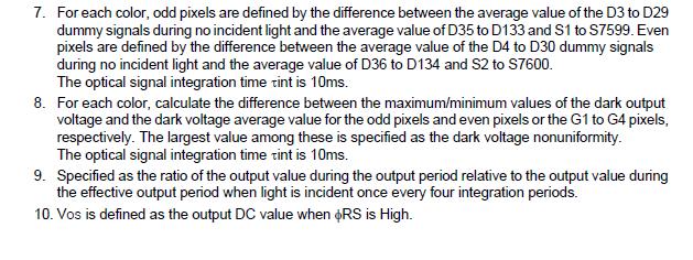
Transcription
 Pixel size 9.3 µm x 9.3 µm Pixel spacing 9.3 µm Line spacing (R-G-B) 9.")

 CDS = Correlated Double Sampling. Noise-reduction technology, increase of photosensitivity.")

1 Color Line Scan Camera SK22800CJRC-XC 3 x 7600 pixels, 9.3 µm x 9.3 µm, 30/50 MHz pixel frequency Camera Sensor Type SK22800CJRC-XC Triple Line Sensor ILX146K 1 2 Pixel number 3 x 7600 (R-G-B) Pixel size 9.3 µm x 9.3 µm Pixel spacing 9.3 µm Line spacing (R-G-B) 9.3 µm Active length Anti-Blooming Integration Control CDS 1 Pixel frequency Line frequency max Line frequency min mm no no yes 30 / 50 MHz 6.17 khz 0.05 khz Integration time max 20 ms 2 Integration time min Dynamic range Spectral range Video signal ms 1:1000 (30 MHz) nm 24-bit (3 x 8-bit) Interface: Interface Voltage +5 V, +15 V Power consumption 7 W Casing (W x H x D) 84 mm x 120 mm x 46 mm Objective mount M72 x 0.75 Weight 0.42 kg Working temperature +5 C to +45 C 1) CDS = Correlated Double Sampling. Noise-reduction technology, increase of photosensitivity. 2) Longer exposure times are possible in trigger mode "External Trigger" Smart line scan camera SK22800CJRC-XC Interface: with Focus adapter FA26XC-S55 Extension ring ZR55-15 Lens adapter AC46-55 Macro lens inspec.x L 5.6/105 ß-0.76 Contents Section Page Section Page 1. Introducing the SK22800CJRC-XC Color Camera 2 2. Connections and I/O Signals 2 3. Interface 3 4. Camera Control and SkCLConfig Gain / Offset and White Balance To Set and Read Camera Parameters 5 5. RGB Sensors: 2D Imaging and Pixel Allocation 6 6. Control Signals and Timing Diagram 7 7. Sensor Performance Specifications 8 8. Dimensions Warranty Accessories 12 SK22800CJRC-XC Kieler Str. 212, Hamburg, Germany Tel: Fax: info@sukhamburg.de

2 1. Introducing the SK22800CJRC-XC Color Line Scan Camera The successful use of the line scan camera requires that the complete optical system is properly set up, especially the location of the illumination, the degree of focus of the objective and the aperture setting. The most critical factor is the perpendicular alignment of the sensor axis either with the object to be measured or the direction of its relative travel when scanned. The scan velocity must be synchonized with the line rate of the camera and is influenced by the exposure time and by the magnification. Schäfter+Kirchhoff supplies the operating program SkLineScan for certified grabber boards, including Teledyne DALSA X64 XCelera-CL, µenable III Silicon Software, National Instruments PCI-1428, and the Matrox Solios. The zoom function of the SkLineScan oscilloscope display of the line camera signal accelerates the optimal parameterization of the camera and alignment of the optical system. SkLineScan can be customized for a particular grabber board on request. Data acquisition requires a grabber which conforms to the CameraLink TM Base configuration. Exposure time and line rate of the camera can be controlled internally by serial commands or externally via the grabber board. The configuration program SkCLConfig allows the full parameterization of the camera settings, such as gain, offset and pixel frequency, via the CameraLink TM serial port interface. SkCLConfig uses the clser ***. dll driver that is supplied with the CameraLink grabber board and personalized applications can also be developed using the SDKs available from the grabber manufacturer. The cameras are supplied precalibrated, with factory settings for gain and offset that can be changed according to requirements using the supplied software. Significant losses in signal quality do accrue when the gain or offset parameters are set incorrectly. The gain and offset values in current use are stored in the camera in non-volatile memory and are immediately available when the camera is reactivated or switched on. 2. Connections and I/O Signals Data Power Data Connector: Mini-D ribbon, female 26-pin Data Connector: Mini-D ribbon, female 26-pin Signal Pin Pin Signal Power Connector: Hirose series HR10A, female 6-pin Power Connector: Hirose series HR10A, female 6-pin + 5 V ± 5% ca. 420 ma (30 MHz Clock) ca. 470 ma (50 MHz Clock) +15 V ± 5% ca. 350 ma Signal Pin Signal Pin + 15 V V V 2 GND V 3 GND 6 GND 1 o o 14 GND X0-2 o o 15 X0+ X1-3 o o 16 X1+ X2-4 o o 17 X2+ Xclk- 5 o o 18 Xclk+ X3-6 o o 19 X3+ SerTC+ 7 o o 20 SerTC- SerTFG- 8 o o 21 SerTFG+ CC1 9 o o 22 CC1+ CC2+ 10 o o 23 CC2- CC3-11 o o 24 CC3+ CC4+ 12 o o 25 CC4- GND 13 o o 26 GND Page 2
3 3. Interface Camera control The CameraLink interface provides four LVDS signals dedicated to camera control (CC1 to CC4). Only CC1 is used by the SK22800CJRC-XC to synchronize with external events. Signal Name I/O Type Description TRIG1 I RS644 CC1 - Synchronization input (SOS) I = Input, O = Output, IO = Bidirectional, P = Power/Ground, NC = not connected. Warning: CC3 to CC4 are not used. Video data The differential LVDS signals X0-X3 and XCLK are reserved for the transmission of highspeed video data from the camera to the grabber board. The video data is transmitted using numerous serial channels simultaneously, according to the protocol for the channel link chipset from National Semiconductor. The CameraLink standard defines the names of the pixel signals, the description of the signal level and the pin assignments and pinout of the chip. Signal Name I/O Type Description R[0 7] O RS644 Red pixel data, 0 = LSB, 7 = MSB G[0 7] O RS644 Green pixel data, 0 = LSB, 7 = MSB B[0 7] O RS644 Blue pixel data, 0 = LSB, 7 = MSB STROBE O RS644 Output data clock Data are valid for a rising edge LVAL O RS644 Line Valid, active High Signal I = Input, O = Output, IO = Bidirectional, P = Power/Ground, NC = not connected. Warning: FVAL and DVAL are not used here as defined in the CameraLink standard. FVAL is always set to the value = 1 (high). DVAL is always set to the value = 1 (high). For a single output, the data is output as ODD (multiplex). Bit allocation 24-bit (3*8-bit) data (F24) Bit DS90CR285 Pin Name Bit DS90CR285 Pin Name Bit DS90CR285 Pin Name Bit DS90CR285 Pin Name R 0 Tx0 R 7 Tx5 G 6 Tx19 B 5 Tx14 R 1 Tx1 G 0 Tx7 G 7 Tx20 B 6 Tx10 R 2 Tx2 G 1 Tx8 B 0 Tx21 B 7 Tx11 R 3 Tx3 G 2 Tx9 B 1 Tx22 STROBE TxCLK R 4 Tx4 G 3 Tx12 B 2 Tx16 LVAL Tx24 R 5 Tx6 G 4 Tx15 B 3 Tx17 R 6 Tx27 G 5 Tx18 B 4 Tx13 The bit allocation conforms to the CameraLink Standard basic configuration. Serial communication Signal Name I/O Type Description SerTFG O RS644 Differential pair for serial communications to the grabber board SerTC 1 RS644 Differential pair for serial communications from the grabber board I = Input, O = Output, IO = Bidirectional, P = Power/Ground, NC = not connected. The CameraLink interface supports two LVDS signal pairs for communication between the camera and grabber board, which conform with the RS232 protocol for asynchronous communication: full duplex, no handshake 9600 baud, 8-bit, no parity bit, 1 stop bit. Page 3


. The signal measuring range is delimited by using the offset value to set the baseline signal and gain to set the maximum signal.")
4 4. Camera Control The software requires that the clser***.dll supplied with the Camera Link grabber board is installed. The most important camera functions can be set using serial commands, by using either the software from the grabber manufacturer or by using the configuration program SkCLConfig tool from Schäfter+Kirchhoff. SkCLConfig provides the direct adjustment of line scan camera parameters, such as gain, offset, and pi xel frequency, via the serial channel of the CameraLink interface. On startup, the camera declares information about type, revision and serial number. If the camera type field is empty then switch off the camera, check the connections and restart. 4.1 Gain / Offset and White Balance The camera is shipped prealigned with gain and offset factory settings. On startup, the RGB odd/even sliders register the gain and offset values already stored in the camera. Customized settings for gain or offset can be programmed using the SkCLConfig tool either by sliding the registers with the mouse or by entering camera parameters directly using the 'Set Command' (see facing table). The signal measuring range is delimited by using the offset value to set the baseline signal and gain to set the maximum signal. After white balance adjustments, the signals are coincident and compensated for all pixels across all sensors. B C A Offset After blocking all light reaching the line sensor, bring the individual video signals close to zero using the R, G and B odd/even offset sliders. The line signal should be just visible in the oscilloscope display. B Gain Now fully illuminate the sensor and move the R, G and B gain sliders to provide a slight overexposure for maximum signal clipping (for 8-bit: 255 or slightly above, for 12-bit: 4095). The parameter settings are stored within the list using Select and are retained for immediate subsequent use even after a complete shut down. C White Balance White Balance is a procedure used for compensating for the different sensitivities in the R, G and B signals. A reference signal for white balance is obtained by taking an image of a plain white surface. The R, G and B gain factors can be used to regulate the signals directly. Page 4
5 4.2 Serial Commands Set Commands Read Commands Set Operation Goooo<CR> Boooo<CR> Hoooo<CR> Joooo<CR> Description Gain 1 (Red odd) 0-20 db Gain 2 (Red even) 0-20 db Gain 3 (Green odd) 0-20 db Gain 4 (Green even) 0-20 db [ oooo<cr> Gain 5 (Blue odd) 0-20 Oppp<CR> Pppp<CR> Qppp<CR> Uppp<CR> Gain 6 (Blue even) 0-20 db Off1 (Red odd) Off2 (Red even) Off3 (Green odd) Off4 (Green even) ] ppp<cr> Off5 (Blue odd) _ppp<cr> C30<CR> C50<CR> T0<CR> T1<CR> M0<CR> M1<CR> M2<CR> Wyyyyy<CR> Xyyyyy<CR> Off6 (Blue even) Camera Clock: 30 MHz Camera Clock: 50 MHz Test pattern off Test pattern on Free Run with selected line rate External Trigger CC1 Free Run with maximum line rate Line rate (yyyyy = Hz) Exposure time (yyyyy = µs) Range of values: oooo = , ppp = yyyyy = 5 digits integer value as ASCII Return confirmation: 0 = OK, 1 = not OK Before adjustment of the exposure time or line rate by using the commands 'W' and 'X', the camera must be put into the 'Free Run' mode using command 'M0'. When using the grabber board to control exposure time then the camera must be set to mode 'External Trigger CC1' using command 'M1'. Request Return Description K<CR> SK22800CJRC-XC SK type number R<CR> Rev3.01 Revision number S<CR> SNr00163 Serial number I1<CR> VCC: yyyyy VCC (1=10mV) I2<CR> VDD: yyyyy VDD (1=10mV) I3<CR> moo: yyyyy mode of operation I4<CR> CLo: yyyyy clock low frequency (MHz) I5<CR> CHi: yyyyy clock high frequency (MHz) I6<CR> Ga1: yyyyy gain 1 I7<CR> Ga2: yyyyy gain 2 I8<CR> Of1: yyyyy offset 1 I9<CR> Of2: yyyyy offset 2 I10<CR> Ga3: yyyyy gain 3 I11<CR> Ga4: yyyyy gain 4 I12<CR> Of3: yyyyy offset 3 I13<CR> Of4: yyyyy offset 4 I15<CR> Ga5: yyyyy gain 5 I16<CR> Ga6: yyyyy gain 6 I17<CR> Of5: yyyyy offset 5 I18<CR> Of6: yyyyy offset 6 I20<CR> CLK: yyyyy selected clock freq (MHz) I22<CR> TRM: yyyyy selected trigger mode I24<CR> Exp: yyyyy exposure time (µs) I25<CR> mix: yyyyy min. exposure time (µs) I26<CR> LCK: yyyyy line frequency (Hz) I27<CR> maz: yyyyy max. line frequency (Hz) Page 5


6 5. RGB Sensors: 2D Imaging and Pixel Allocation Triple line sensors have 3 separate sensor lines for the primary colors red, green and blue and can achieve extremely high optical resolutions. The SK22800CJRC-XC color line scan camera has a triple line sensor with 7600 pixels each for red, green and blue. The sensors are directly adjacent, providing an inter-sensor distance of 9.3 µm equivalent to the size of a pixel. 9.3 µm The co lor information originating from the different parts of the object is transmitted in parallel and stored in the PC before being correctly reallocated. Line Pixel line 2 Raw Data R G B R G B R G B R G B R G B R G B R G B R G B R G B R G B R G B R G B... Allocation of color information 9.3 µm RED GREEN BLUE RED GREEN BLUE Signal display - RGB splitting A two-dimensio nal color image is generated by moving the object or the camera, ensuring that the sensor properties, the travel direction and speed are all accounted for: object velocity = pixel width magnification exposure time Triple line sensors require a precise synchronous translation of the object for the correct allocation of pixels A. When these conditions are not met then images with co lor convergence ab er rations are generated B. A B Monochrome font pattern A line synchronous object transport B asynchronous transport of the object causes color convergence aberration During object travel at a translation rate of one pixel per clock pulse, all color information is acquired within 3 clock cycles. An object point reaches the red line sensor first, followed immediately by the green, by which time the red sensor is collecting the next object information, and finally the blue line sensor, by which time the green and red sensors are collecting subsequent slices of object information, respectively. Page 6
7 6. Control Signals and Timing Diagram Input Control Signals The control signals needed to run the CCD line scan camera are "Clock" (CCLK) and "Start Of Scan" (SOS). The clock signal is generated internally by a 50 MHz oscillator. The SOS can be initiated internally by adjusting the Exposure Time or externally by the grabber board. For internal control, the camera must be set in the 'Free Run' mode by using command 'M0'. When the SOS signal is generated by the grabber board then the camera must be set to the 'external Trigger CC1' mode using 'M1'. The frequency of the 'SOS' signal determines the number of lines that are read per second. On the rising edge of this signal, the accumulated charges in the sensor pixels of the analog shift register are read out with each beat of the clock signal. Thus, the frequency of the clock signal determines the speed at which the charges of the individual pixels of the line sensor appear in the camera video output. At each positive edge, the accumulated charges of the subsequent pixels are released as video output. The Clock and 'SOS' signals do not have be synchronized. However, the clock frequency should be sufficiently slow to allow two successive 'SOS' signals to be read out from the line camera. The SK22800CJRC-XC camera requires 8064 clock pulses for a line scan to be read out completely. Larger numbers of clock pulse can be used without restriction. SOS CC1 CCLK STROBE LVAL 458 Clock Cycles 7600 Clock Cycles 6 Clock Cycles 15 ns R[0-7] G[0-7] B[0-7] Video intern for Red, Green, Blue, odd and even Output line scan data generated from the Input (SOS) signal SOS: Start Of Scan: minimum pulse length of 30 ns. The frequency of the SOS signal is directly controlled by the line frequency of the camera. The rising edge of the 'SOS' signal is the start of the signal accumulation process. The accumulated charges within the sensor are transferred to the analog transport registers in parallel with the sensor line information. i = isolation pixels, o = overclocking Page 7
 - Technical Data Sheet Electro-optical Characteristics")
8 7. Sensor Performance Specifications Producer: Type: Data source: Sony ILX146K 7600-pixel 4-line CCD Linear Sensor (Color) - Technical Data Sheet Electro-optical Characteristics Page 8
9 Page 9
10 Block Diagram Page 10


11 8. Dimensions Casing group: CC7 CCD line scan camera, digital Casing thread: M72x0.75 Distance to sensor: 10.4 mm Data Connector: Mini-D ribbon, female 26-pin Power Connector: Hirose series HR10A, female 6-pin Focus adapter FA26XC-S45 51 mm + 28 mm Focus adapter with variable length for with adapter M55x SK22500CNEC-XC and SK22800CJRC-XC for lenses with Leica thread. Compatible with Lens adapter M39-45 and 8 44 Ø f8 M55x0.75 Extension ring ZR-L Focus adapter FA26XC-S55 51 mm + 28 mm Focus adapter with variable length for with adapter M55x SK22500CNEC-XC and SK22800CJRC-XC. Compatible with Lens adapter AC46-55 and Extension ring ZR Ø f8 M55x Page 11
12 9. Warranty 10. Accessories This manual has been prepared and reviewed as carefully as possible but no warranty is given or implied for any errors of fact or in interpretation that may arise. If an error is suspected then the reader is kindly requested to inform us for appropriate action. The circuits, descriptions and tables may be subject to and are not meant to infringe upon the rights of a third party and are provided for informational purposes only. The technical descriptions are general in nature and apply only to an assembly group. A particular feature set, as well as its suitability for a particular purpose, is not guaranteed. The warranty period for the CCD line scan camera when used for the purpose for which it was intended is 24 months. The warranty is immediately void on inappropriate modification, use or damage. EC Declaration of Conformity This product satisfies the requirements of the EC directive 89/336/EEG as well as DIN EN Control cable SK pin shielded cable, both ends with mini-d ribbon connector, male/male MM SK MM Order Code 3 = 3 m cable length 5 = 5 m (standard) x = length of choice (maximum = 100 m) Power supply cable SK Shielded cable with Lumberg SV60 male 6-pin and Hirose HR10A female 6-pin connectors, MF SK MF Order Code 1.5 = 1.5 m standard 3 = 3 m x = length of choice Power Supply: PS Order Code Input: V AC, 50/60 Hz, 0.8 A 3-pin input connection (IEC 320) Output: 5 V DC/2.5 A 15 V DC/0.5 A, -15 V DC/0.3 A output connector: Lumberg KV60 female 6-pin, length 1 m Software: SK91CL-WIN * Order Code SkCLConfig control program for line scan cameras with a CameraLink TM interface (all grabber boards). SkLineScan operating program with oscilloscope display and scan function. Operating system: * Windows XP/2000 For Focus adapter: FA26XC-S45: Mounting ring ZR-L... Order Code Lens adapter M39-45 FA26XC-S55: Mounting ring ZR Lens adapter AC46-55 Lenses: high resolution enlarging and macro lenses high speed scan lenses optimized for infinite imaging, providing high quality images with a flat field area SK22800CJRC-XC Kieler Str. 212, Hamburg, Germany Tel: Fax: info@sukhamburg.de
Color Line Scan Camera SK6288CKOC
 Color Line Scan Camera SK6288CKOC 3 x 2096 pixels, 14 µm x 14 µm, 60/30 MHz pixel frequency Camera Sensor Type SK6288CKOC Triple Line Sensor KLI-2113 1 2 3 Pixel number 3 x 2096 (B-G-R) Pixel size 14 µm
SK22368CTOC-LA. Instruction Manual Color Line Scan Camera. 1 CCD line scan camera
 SK22368CTOC-LA Color Line Scan Camera 3x 7456 pixels, 4.7 µm x 4.7 µm, 150 / 75 MHz pixel frequency Instruction Manual 08.2016 SK22368CTOC-LA Schäfter + Kirchhoff Line Scan Camera SK22368CTOC-LA Manual
SK8160CKO-LB. Instruction Manual Monochrome Line Scan Camera. 1 CCD line scan camera
 SK8160CKO-LB Monochrome Line Scan Camera 8160 pixels 5 µm x 5 µm, pixel frequency 100 / 60 / 30 MHz Instruction Manual 05.2017 SK8160CKO-LB Schäfter + Kirchhoff Line Scan Camera SK8160CKO-LB Manual (05.2017)
Color Line Scan Camera SK22800GJRC-XC
 Color Line Scan Camera SK800GJRC-XC x 7600 pixels (RGB), 9. µm x 9. µm, 10 MHz pixel frequency FAST+ FLEXIBLE Camera SK800GJRC-XC 1 Sensor Type Triple Line Sensor ILX146K Pixel number x 7600 (R-G-B) Pixel
gain/offset programmable very low noise light sensitive CDS technology round housing Ø 65 mm
 www.sukhamburg.de email: info@sukhamburg.de CCD Line Scan Camera Digital b/w SK 048 XSD 048 Pixels, 4 x 4 µm, 0 MHz Pixel Frequency CCD line scan camera SK 048 XSD mounted on Camera mount SK0 Clamp set
The Condor 1 Foveon. Benefits Less artifacts More color detail Sharper around the edges Light weight solution
 Applications For high quality color images Color measurement in Printing Textiles 3D Measurements Microscopy imaging Unique wavelength measurement Benefits Less artifacts More color detail Sharper around
Datasheet. ELIIXA+ 16k/8k CP Cmos Multi-Line Color Camera. Features. Description. Application. Contact us online at: e2v.
 Datasheet ELIIXA+ 16k/8k CP Cmos Multi-Line Color Camera Features Cmos Colour Sensor : - 16384 RGB Pixels, 5 x 5µm (Full Definition) - 8192 RGB Pixels 10x10µm (True Colour) Interface : CoaXPress (4x 6Gb/sLinks)
USB 3.0 SK7456U3TO. Instruction Manual Monochrome Line Scan Camera. 1 CCD line scan camera
 SK7456U3TO Monochrome Line Scan Camera 7456 pixels, 4.7 µm x 4.7 µm, 40 MHz pixel frequency USB 3.0 Robust cable connections Hot-pluggable Perfect for movable setups Instruction Manual 11.2015 SK7456U3TO
Draft. Basler L100k USER S MANUAL
 Draft Basler L100k USER S MANUAL Document Number: DA000509 Version: 06 Language: 000 (English) Release Date: 07 February 2013 For customers in the U.S.A. This equipment has been tested and found to comply
Small Cubic Type 5.0 Mega Pixel CCD Monochrome PoCL Camera Link Camera
 Small Cubic Type 5.0 Mega Pixel CCD Monochrome PoCL Camera Link Camera Product Specifications RICOH COMPANY, LTD. 1/12 Copyright & Disclaimer Sensor Technology Co., Ltd. (DBA Sentech) believes the contents
Draft. Basler A102k USER S MANUAL
 Draft Basler A102k USER S MANUAL Document Number: DA000522 Version: 06 Language: 000 (English) Release Date: 29 June 2007 For customers in the U.S.A. This equipment has been tested and found to comply
USB components. Multi-Sensor Cameras. Camera Configuration. Available Sensor Board Designs. Options. Base unit and sensor boards
 Multi- Cameras Base unit and sensor boards Up to four pixel-synchronous sensors connected to the base unit by flex-foil cable (LVDS data transfer) Free positioning of the external sensors Plug and play
Draft. Basler A202k USER S MANUAL
 Draft Basler A202k USER S MANUAL Document Number: DA0440 Version: 08 Language: 000 (English) Release Date: 29 June 2007 For customers in the U.S.A. This equipment has been tested and found to comply with
ELIIXA+ 8k/4k CL Cmos Multi-Line Colour Camera
 ELIIXA+ 8k/4k CL Cmos Multi-Line Colour Camera Datasheet Features Cmos Colour Sensor : 8192 RGB Pixels, 5 x 5µm (Full Definition) 4096 RGB Pixels 10x10µm (True Colour) Interface : CameraLink (up to 10
UNiiQA+ Color CL CMOS COLOR CAMERA
 UNiiQA+ Color CL CMOS COLOR CAMERA Datasheet Features CMOS Color LineScan Sensors: 4096 pixels, 5x5µm 2048, 1024 or 512 pixels, 10x10µm Interface : CameraLink (Base or Medium) Line Rate : Up to 40 kl/s
Datasheet. AViiVA M4 CL Camera Link Line Scan Camera 160 MHZ
 Camera Link Line Scan Camera 160 MHZ Datasheet Features High Sensitivity and High Dynamic Performance Linear CCD Resolution: 2048 Pixels with 14 µm Square Pixels 6144 or 8192 Pixels with 7 µm Square Pixels
Tri-Linear Series: BMT-2098C-A User Manual
 Tri-Linear Series: BMT-2098C-A User Manual Colour Line Scan Analog Camera BalaJi MicroTechnologies Pvt. Ltd. (A Unit of B.B. Group of Companies) Corporate Headquarter: New Delhi, India Sales/business Operation:
Revision History. VX Camera Link series. Version Data Description
 Revision History Version Data Description 1.0 2014-02-25 Initial release Added Canon-EF adapter mechanical dimension 1.1 2014-07-25 Modified the minimum shutter speed Modified the Exposure Start Delay
MS4000 and MS4100 High-Resolution Digital Color and Multispectral Camera
 MS4000 and MS4100 High-Resolution Digital Color and Multispectral Camera User Manual DuncanTech 11824 Kemper Rd. Auburn, CA 95603 Phone: (530)-888-6565 Fax: (530)-888-6579 Web: www.duncantech.com Email:
SIMPLY PRECISE PRELIMINARY. Preliminary product overview - LAK encoder. LAK 1 Absolute linear encoder with signal control
 PRELIMINARY Preliminary product overview - LAK encoder LAK 1 Absolute linear encoder with signal control 2 Index 1. Overview 3 2. Applications 3 3. Technical data 4 4. General specifications 5 5. Dimensions
Basler sprint USER S MANUAL FOR COLOR CAMERAS
 Basler sprint USER S MANUAL FOR COLOR CAMERAS Document Number: AW000699 Version: 11 Language: 000 (English) Release Date: 17 July 2017 For customers in the USA This equipment has been tested and found
SkLineScan-GigE-WIN. CCD Line Scan Camera System. Windows 7 (32 / 64 bit) Version /2015. Software program. Manual
 Version /2015. Software program. Manual") CCD Line Scan Camera System Software program SkLineScan-GigE-WIN Manual Windows 7 (32 / 64 bit) Version 5.3.0 07/2015 Kieler Str. 212 D-22525 Hamburg phone: +49(0)40 853997 0 fax: +49(0)40 853 99779 email:
CCD Line Scan Camera System Software program SkLineScan-GigE-WIN Manual Windows 7 (32 / 64 bit) Version 5.3.0 07/2015 Kieler Str. 212 D-22525 Hamburg phone: +49(0)40 853997 0 fax: +49(0)40 853 99779 email:
Baumer TXF50 Art. No: OD107988
 Digital Monochrome (b/w) Progressive Scan Camera System: IEEE1394b Baumer TXF50 Art. No: OD107988 FireWire TM IEEE1394b (800 Mbit / sec) progressive scan CCD-camera 2448 x 2050 pixel Up to 15 full frames
Datasheet. AViiVA UM8 CL 12k Pixels Camera Link Line Scan Camera 320 MHz
 Camera Link Line Scan Camera 320 MHz Datasheet Features High Sensitivity and high SNR Performance Linear CCD 12288 Resolution with 5 µm Square Pixels 100% Aperture, Built-in Anti-blooming, No Lag Camera
SK512GSD-4. Instruction Manual. Monochrome Line Scan Camera. 1 CCD line scan camera
 1.0 0.0 400 600 800 1000 SK512GSD-4 Monochrome Line Scan Camera 512 pixels 14 x 14 µm², line frequency up to 53.5 khz Spectral range Wavelength (nm) Line scan camera with 53.5 khz maximum line rate, large
Datasheet. AViiVA EM2 EM4 CL Line Scan Camera
 Line Scan Camera Datasheet Main Features Sensor: 2048 14 x 14 µm or 4096 10 x 10 µm Pixels Interface: Camera Link Base for EM2, Base/Medium for EM4 Data rate: EM2: 80 Mpixel/s EM4: 160 Mpixel/s Bit Depth:
Basler sprint USER S MANUAL FOR MONO CAMERAS
 Basler sprint USER S MANUAL FOR MONO CAMERAS Document Number: AW000162 Version: 06 Language: 000 (English) Release Date: 12 September 2008 For customers in the U.S.A. This equipment has been tested and
Baumer FWX05c-II NeuroCheck Edition
 Digital Color Progressive Scan Camera System: IEEE1394a Baumer FWX05c-II NeuroCheck Edition Art. No.: OD106154 IEEE1394a (FireWire TM ) Progressive Scan CCD Camera 780 x 582 Pixels Outstanding Color Fidelity
Changed the User Manual file name Deleted VC-4MC-40 model Added VC-3MC-280 model Added VC-25MC-30 model
 Revision History Revision Date Description 1.0 2010-10-01 Initial release 1.1 2010-12-13 Added scl and gcl command 1.2 2010-12-21 Added VC-2MC-M/C340 model 1.3 2011-04-07 Revised Max. Frame Rate 1.4 2011-07-12
DRAFT. Basler A500k USER S MANUAL
 DRAFT Basler A500k USER S MANUAL Document Number: DA000570 Version: 07 Language: 000 (English) Release Date: 20 March 2007 For customers in the U.S.A. This equipment has been tested and found to comply
NanEye GS NanEye GS Stereo. Camera System
 NanEye GS NanEye GS Stereo Revision History: Version Date Modifications Author 1.0.1 29/05/13 Document creation Duarte Goncalves 1.0.2 05/12/14 Updated Document Fátima Gouveia 1.0.3 12/12/14 Added NanEye
Basler sprint USER S MANUAL FOR COLOR CAMERAS
 Basler sprint USER S MANUAL FOR COLOR CAMERAS Document Number: AW000699 Version: 09 Language: 000 (English) Release Date: 31 May 2013 For customers in the U.S.A. This equipment has been tested and found
User Manual MV1-D1312C CameraLink Series CMOS Area Scan Colour Camera
 User Manual MV1-D1312C CameraLink Series CMOS Area Scan Colour Camera MAN046 10/2010 V1.1 All information provided in this manual is believed to be accurate and reliable. No responsibility is assumed
Data Sheet SMX-160 Series USB2.0 Cameras
 Data Sheet SMX-160 Series USB2.0 Cameras SMX-160 Series USB2.0 Cameras Data Sheet Revision 3.0 Copyright 2001-2010 Sumix Corporation 4005 Avenida de la Plata, Suite 201 Oceanside, CA, 92056 Tel.: (877)233-3385;
Datasheet. AViiVA EM2 EM4 CL Line Scan Camera for Machine Vision. Main Features Sensor: x 14 µm Pixel. Product Description
 AViiVA EM2 EM4 CL Line Scan Camera for Machine Vision Datasheet Main Features Sensor: 512 14 x 14 µm Pixel 1024 14 x 14 µm Pixel 2048 14 x 14 µm Pixel or 4096 10 x 10 µm Pixel Interface: Camera Link Base
allpixa camera Manual CD40067 R04
 allpixa camera Manual CD40067 R04 2018-07-12 Table of Contents 1 General Information... 8 1.1 About Chromasens... 8 Contact information... 8 Support... 8 1.2 Firmware and software version in this manual...
The power consumption and the heat of the PC will increase whenever the power save mode is disabled. Please
 Caution for PCs with Intel Core i3, i5 or i7 - If the USB camera is used with a PC that has the Intel Core I series (i3, i5 and i7) chipset, the following problems may occur: An image cannot be obtained
CLB-501B CAMERA LINK BREAKOUT BOX. User s Manual. Document # , Rev 0.2, 3/23/2012 preliminary
 CLB-501B CAMERA LINK BREAKOUT BOX User s Manual Document # 201107, Rev 0.2, 3/23/2012 preliminary Vivid Engineering 159 Memorial Drive, Suite F Shrewsbury, MA 01545 Phone 508.842.0165 Fax 508.842.8930
allpixa camera Manual
 allpixa camera Manual CD40067 Version 3.4 Table of Contents 1 About Chromasens 7 1.1 Contact information 7 1.2 Support 7 2 General 8 2.1 Firmware and software version in this manual 8 2.2 List of abbreviations
Rad-icon Imaging Corp A Division of DALSA Corporation
 Rad-icon Imaging Corp A Division of DALSA Corporation el: 408-486-0886 Fax: 408-486-0882 www.rad-icon.com PRELIMINARY DAA SHEE SkiaGraph 8 Very Large Area X-Ray Camera Key Features: Active area of 20 cm
pco.dimax digital high speed 12 bit CMOS camera system
 dimax digital high speed 12 bit CMOS camera system 1279 fps @ full resolution 2016 x 2016 pixel 12 bit dynamic range 4502 fps @ 1008 x 1000 pixel color & monochrome image sensor versions available exposure
Basler A400k USER S MANUAL
 Basler A400k USER S MANUAL Document Number: DA00062412 Release Date: 14 January 2009 For customers in the U.S.A. This equipment has been tested and found to comply with the limits for a Class A digital
User Manual MV1-D1312(I) CameraLink Series CMOS Area Scan Camera
 CameraLink Series CMOS Area Scan Camera") User Manual MV1-D1312(I) CameraLink Series CMOS Area Scan Camera MAN041 09/2010 V2.5 All information provided in this manual is believed to be accurate and reliable. No responsibility is assumed by Photonfocus
User Manual MV1-D1312(I) CameraLink Series CMOS Area Scan Camera MAN041 09/2010 V2.5 All information provided in this manual is believed to be accurate and reliable. No responsibility is assumed by Photonfocus
Datasheet. AViiVA SC2 LV LVDS Color Linescan Camera
 LVDS Color Linescan Camera Datasheet Features High Sensitivity and High SNR Performance Linear CCD Sensor Monoline 1365 RGB Patterns (Total of 4096 Active Pixels) Built-in Anti-blooming, No Lag EIA-644
Fast, flexible, highly reliable image acquisition
 Fast, flexible, highly reliable image acquisition The X64-CL Express is a Camera Link frame grabber that is based on the PCI Express x1 interface next generation bus interface technology for the host PCs.
POSICHRON position sensor in stick design. Protection class. Voltage: V, 3 wire Current: ma, 3 wire
 POSICHRON Position Sensor Stick Design with Analog Specifications POSICHRON position sensor in stick design Protection class IP67 Measurement range 0... 100 up to 0... 5750 mm Absolute position measurement
GFT1504 4/8/10 channel Delay Generator
 Features 4 independent Delay Channels (10 in option) 100 ps resolution (1ps in option) 25 ps RMS jitter (channel to channel) 10 second range Channel Output pulse 6 V/50 Ω, 3 ns rise time Independent control
Linea Color CL. Camera User s Manual. 4k and 8k Color CMOS Line Scan. P/N:
 Linea Color CL Camera User s Manual 4k and 8k Color CMOS Line Scan sensors cameras frame grabbers processors software vision solutions P/N: 03-032-20231-02 www.teledynedalsa.com Notice 2017 Teledyne DALSA
ArduCAM USB Camera Shield
 ArduCAM USB Camera Shield Application Note for MT9V034 Rev 1.0, June 2017 Table of Contents 1 Introduction... 2 2 Hardware Installation... 2 3 Run the Demo... 3 4 Tune the Sensor Registers... 4 4.1 Identify
Variable Gain Photoreceiver Fast Optical Power Meter
 The picture shows model -FC with fiber optic input. Features InGaAs-PIN detector, active diameter 0.3 mm (free space versions), 80 µm integrated ball lens (FC version) Spectral range 900-1700 nm Very low
Piranha4 Polarization
 Piranha4 Polarization Camera User s Manual 2k High Speed Polarization Line Scan sensors cameras frame grabbers processors software vision solutions P/N: 03-032-20245-01 www.teledynedalsa.com Notice 2017
Four-channel Digital Electrometer for Quadrant BPM Readout
 Four-channel Digital Electrometer for Quadrant BPM Readout Features Four independent integrator channels with common gate Dynamic range
User Manual MV-D1024E CameraLink Series CMOS Area Scan Cameras
 User Manual MV-D1024E CameraLink Series CMOS Area Scan Cameras MAN028 03/2008 V1.3 All information provided in this manual is believed to be accurate and reliable. No responsibility is assumed by Photonfocus
Absolute Encoders Multiturn
 The Sendix F36 multiturn with the patented Intelligent Scan Technology is an optical multiturn encoder in miniature format, without gears and with 00% insensitivity to magnetic fields. With a size of just
Variable Gain Photoreceiver Fast Optical Power Meter
 The picture shows model -FC with fiber optic input. Features Si-PIN detector, active area 1.1 x 1.1 mm 2 Spectral range 190-1000 nm Very low noise, NEP down to 17 fw/ Hz Bandwidth up to 500 khz Conversion
SW-2000M-CL-80. User's Manual. CMOS High Speed Monochrome Camera Link Line Scan Camera SW-2000M-CL-80. Document Version: 1.
 User's Manual SW-2000M-CL-80 CMOS High Speed Monochrome Camera Link Line Scan Camera Document Version: 1.3 Date: May, 2015 File: Manual_SW-2000M-CL-80_rev_1.3.docx 1 Notice The material contained in this
ELiiXA+ NBASE-T CMOS MULTI-LINE COLOUR CAMERA
 ELiiXA+ NBASE-T CMOS MULTI-LINE COLOUR CAMERA Datasheet Features Cmos Colour Sensor : 4096 RGB Pixels 5x5µm (Full Definition) 2048 RGB Pixels 10x10µm (True Colour) Interface : NBASE-T (up to 5Gb/s) Line
GigE Vision Extended-Depth-of-Field Camera
 GigE Vision Extended-Depth-of-Field Camera EV-G030B1 (VGA, Monochrome) EV-G200C1 / EV-G200B1 (UXGA, Color /Monochrome) Product Specifications RICOH COMPANY, LTD. 1 Safety Precautions CAUTION RISK OF ELECTRIC
Agilent AEDA-3300 Series Ultra Miniature, High Resolution Incremental Kit Encoders Data Sheet
 Description The AEDA-3300 series are high performance, cost effective, three-channel optical incremental encoder modules with integrated bearing stage. By using transmissive encoder technology to sense
Technical data. General specifications. Linearity error ± 0.1 Electrical specifications Operating voltage U B
 Model Number SYNCHRON SERIELLES INTERFACE Features Very small housing Up to 32 Bit multiturn SSI interface Free of wear magnetic sampling High resolution and accuracy Description The ENA36IL series are
CMOS MT9V034 Camera Module 1/3-Inch 0.36MP Monochrome Module Datasheet
 CMOS MT9V034 Camera Module 1/3-Inch 0.36MP Monochrome Module Datasheet Rev 1.0, Mar 2017 Table of Contents 1 Introduction... 2 2 Features... 3 3 Block Diagram... 3 4 Application... 3 5 Pin Definition...
Manual IF2008A IF2008E
 Manual IF2008A IF2008E PCI Basis Board Expansion Board Table of Content 1 Technical Data... 4 1.1 IF2008A Basic Printed Circuit Board... 4 1.2 IF2008E Expansion Board... 5 2 Hardware... 6 2.1 View IF2008A...
Basler. GigE Vision Line Scan, Cost Effective, Easy-to-Integrate
 Basler GigE Vision Line Scan, Cost Effective, Easy-to-Integrate BASLER RUNNER Are You Looking for Line Scan Cameras That Don t Need a Frame Grabber? The Basler runner family is a line scan series that
LASER. Analog Laser Displacement Transducer. LAM Series. Key-Features: Content:
 LASER Analog Laser Displacement Transducer LAM Series Key-Features: Content: Overview, Measuring Principle...2 Installation Instructions...3 Technical Data...4 Technical Drawings.7 Electrical Connection...9
sensicam em electron multiplication digital 12bit CCD camera system
 sensicam em electron multiplication digital 12bit CCD camera system electron multiplication gain of up to 1000 superior resolution (1004 1002 pixel) for EMCCD extremely low noise < 1e excellent quantum
NI 6013/6014 Family Specifications
 NI 6013/6014 Family Specifications This document lists the I/O terminal summary and specifications for the NI 6013/6014 family of devices. This family includes the following devices: NI PCI-6013 NI PCI-6014
Volume III July, 2009
 July, 009 1 Bit Grayscale Camera for Industrial Application he electronics of the new 1 bit T Grayscale Camera is capable of capturing the gray image with 1 bit grayscale (4096 levels). The resolution
ELECTRONICS FOR PULSE PICKERS
 Rev. 3.07 / 2014 04 10 ELECTRONICS FOR PULSE PICKERS TABLE OF CONTENTS Description... 2 High voltage switches... 3 Appearance / dimensions... 3 Power ratings... 3 Interfaces... 4 Specifications... 6 How
Absolute Encoders - Singleturn
 The Sendix 5853 and Sendix 5873 singleturn encoders with SSI or BiSS interface and optical sensor technology can achieve a resolution of max. 7 bits. These encoders are also available with an optional
Protection class. Male 8 pin socket M12 (ADCANOP: 5 pin socket)
") WS10SG Analog, SSI or CANopen Output Very compact sensor for industrial applications Protection class IP65 Measurement range 0... 100 mm to 0... 1250 mm Analog output or A/D converted synchronous serial
WS10SG Analog, SSI or CANopen Output Very compact sensor for industrial applications Protection class IP65 Measurement range 0... 100 mm to 0... 1250 mm Analog output or A/D converted synchronous serial
Basler. Line Scan Cameras
 Basler Line Scan Cameras High-quality line scan technology meets a cost-effective GigE interface Real color support in a compact housing size Shading correction compensates for difficult lighting conditions
Rad-icon Large-Area Industrial X-Ray Detectors
 Rad-icon Large-Area Industrial X-Ray Detectors Overview Key Features Large-area, tiled detectors with active area up to 30 x 30 cm 5 or 10 lp/mm resolution (99 or 49.5µm pixel) Gigabit Ethernet or Camera
velociraptor HS Velociraptor is fast running and fast grabbing! Save a tree...please don't print this document unless you really need to.
 velociraptor HS High-speed FPGA-based camera family for Video recording Product Brief v1.6 COPYRIGHT 2014 by OPTOMOTIVE, MECHATRONICS Ltd. All rights reserved. The content of this publication may be subject
Artifex LIV 110. Laser Diode Characterization System. Engineering
 Artifex Engineering LIV 110 Laser Diode Characterization System Artifex Engineering e.k. General Manager: Dr. Steven Wright Tel: +49-(0)4921-58908-0 Dortmunder Str. 16-18 Registry number: HRA 200036 email:
Interfaces: 1 Line Scan Camera 2 Power Supply 3 Illumination 4 Network cable (CAT 6)
") Line Scan Cameras from to 800 pixels, monochrome or color or TDi Interfaces: Schäfter+Kirchhoff offers two types of line scan camera with a Gigabit Ethernet interface. The hardware is technically identical
Line Scan Cameras from to 800 pixels, monochrome or color or TDi Interfaces: Schäfter+Kirchhoff offers two types of line scan camera with a Gigabit Ethernet interface. The hardware is technically identical
ColorRanger E 3D Cameras. Explore the true colors of Ranger MultiScan. PDF processed with CutePDF evaluation edition
 P r o d u c t I n f o r m at i o n ColorRanger E D Cameras Explore the true colors of Ranger MultiScan PDF processed with CutePDF evaluation edition www.cutepdf.com ColorRanger E: High-speed D and color
GFT Channel Digital Delay Generator
 Features 20 independent delay Channels 100 ps resolution 25 ps rms jitter 10 second range Output pulse up to 6 V/50 Ω Independent trigger for every channel Four triggers Three are repetitive from three
Voltage regulator TAPCON 240
 Voltage regulator TAPCON 240 Supplement 2398402/00 Protocol description for IEC 60870-5-103 All rights reserved by Maschinenfabrik Reinhausen Copying and distribution of this document and utilization and
Absolute Encoders Multiturn
 Absolute Encoders Multiturn Functional Safety, optical The absolute multiturn encoders Sendix 5863 SIL and 5883 SIL are perfectly suited for use in safety-related applications up to SIL3 according to DIN
Selection guide. Communication accessories. Communication accessory selection guide. Characteristics
 Communication accessories Selection guide There are 2 types of Sepam communication accessories: b communication interfaces, which are essential for connecting Sepam to the communication network b converters
Interfaces: 1 Line Scan Camera. 3 Illumination 4 Network cable (CAT 6)
") Line Scan Cameras from to 800 pixels, monochrome or color or TDi Interfaces: Schäfter+Kirchhoff offers two types of line scan camera with a Gigabit Ethernet interface. The hardware is technically identical
Line Scan Cameras from to 800 pixels, monochrome or color or TDi Interfaces: Schäfter+Kirchhoff offers two types of line scan camera with a Gigabit Ethernet interface. The hardware is technically identical
Basler. Line Scan Cameras
 Basler Line Scan Cameras Next generation CMOS dual line scan technology Up to 140 khz at 2k or 4k resolution, up to 70 khz at 8k resolution Color line scan with 70 khz at 4k resolution High sensitivity
APPLICATION BULLETIN. SERIAL BACKGROUNDER (Serial 101) AB23-1. ICS ICS ELECTRONICS division of Systems West Inc. INTRODUCTION CHAPTER 2 - DATA FORMAT
 AB23-1. ICS ICS ELECTRONICS division of Systems West Inc. INTRODUCTION CHAPTER 2 - DATA FORMAT") ICS ICS ELECTRONICS division of Systems West Inc. AB- APPLICATION BULLETIN SERIAL BACKGROUNDER (Serial 0) INTRODUCTION Serial data communication is the most common means of transmitting data from one point
ICS ICS ELECTRONICS division of Systems West Inc. AB- APPLICATION BULLETIN SERIAL BACKGROUNDER (Serial 0) INTRODUCTION Serial data communication is the most common means of transmitting data from one point
maxon document number:
 maxon document number: 791272-04 1 Table of contents... 2 2 Table of figures... 3 3 Introduction... 4 4 How to use this guide... 4 5 Safety Instructions... 5 6 Performance Data... 6 6.1 Motor data... 6
Parameter Value Unit Notes
 Features Single axis measurement from ±5 to ±60 High resolution and accuracy. Low temperature drift, with optional temperature compensation to further improve temperature performance. RS232 and RS485 output
Basler. Aegis Electronic Group. GigE Vision Line Scan, Cost Effective, Easy-to-Integrate
 Basler GigE Vision Line Scan, Cost Effective, Easy-to-Integrate BASLER RUNNER Are You Looking for Line Scan Cameras That Don t Need a Frame Grabber? The Basler runner family is a line scan series that
Introduction to Computer Vision
 Introduction to Computer Vision CS / ECE 181B Thursday, April 1, 2004 Course Details HW #0 and HW #1 are available. Course web site http://www.ece.ucsb.edu/~manj/cs181b Syllabus, schedule, lecture notes,
ICAM. Electronics & Software. Industrial Charge Amplifier for Applications in Manufacturing. Type 5073A...
 Electronics & Software ICAM Type 5073A... Industrial Charge Amplifier for Applications in Manufacturing The ICAM charge amplifier (Industrial Charge Amplifier Manufacturing) converts the piezoelectric
Technical data. General specifications V DC Power consumption P 0. 1 W Time delay before availability t v
 Model Number SYNCHRON SERIELLES INTERFACE Features Very small housing Up to 32 Bit multiturn SSI interface Free of wear magnetic sampling High resolution and accuracy Description The ENA36IL series are
MV-D640 User s Manual
 All information provided in this manual is believed to be accurate and reliable. No responsibility is assumed by Photonfocus AG for its use. Photonfocus AG reserves the right to make changes to this information
ISOBE5600. Data sheet. Isolated Probe Systems. - ISOBE5600 Isolation system - ISOBE5600 Transient recorder. Features and Benefits
 ISOBE5600 Isolated Probe Systems - ISOBE5600 Isolation system - ISOBE5600 Transient recorder Data sheet Features and Benefits ISOBE5600 Isolation system - Cost-effective - Fiber-optic isolation - Analogue-in
Ionization Chamber Controller with Integrated HV Supply
 Ionization Chamber Controller with Integrated HV Supply Features Dynamic range
WaveStation Function/Arbitrary Waveform Generators
 Function/Arbitrary Waveform Generators Key Features High performance with 14-bit waveform generation, up to 500 MS/s sample rate and up to 512 kpts memory 2 channels on all models Large color display for
Using the USB2.0 camera and guider interface
 Using the USB2.0 camera and guider interface The USB2.0 interface is an updated replacement for the original Starlight Xpress USB1.1 unit, released in 2001. Its main function is to provide a USB2 compatible
W(G)S3.1 Position Sensor with Analog or A/D converted synchronous serial output
S3.1 Position Sensor with Analog or A/D converted synchronous serial output") W(G)S3.1 Position Sensor with Analog or A/D converted synchronous serial output Position and Velocity Sensor for Long Ranges Protection Class IP50 Measurement Range: 0... 10000 mm to 0... 15000 mm 0...
W(G)S3.1 Position Sensor with Analog or A/D converted synchronous serial output Position and Velocity Sensor for Long Ranges Protection Class IP50 Measurement Range: 0... 10000 mm to 0... 15000 mm 0...
DS1075. EconOscillator/Divider PRELIMINARY FEATURES PIN ASSIGNMENT FREQUENCY OPTIONS
 PRELIMINARY EconOscillator/Divider FEATURES Dual Fixed frequency outputs (200 KHz 100 MHz) User programmable on chip dividers (from 1 513) User programmable on chip prescaler (1, 2, 4) No external components
Features. Description. General Specifications. VS Series Inclinometer : Dual Axis, RS232 and Analogue Output
 Features Dual axis measurement from ±5 to ±60 High resolution and accuracy Low temperature drift, with optional temperature compensation to further improve temperature performance. RS232 output interface
Voltage regulator TAPCON 260
 Voltage regulator TAPCON 260 Supplement 2531975/00 Protocol description for IEC 60870-5-103 All rights reserved by Maschinenfabrik Reinhausen Copying and distribution of this document and utilization and
Absolute encoder GEL 15X F. Serial (SSI) or parallel interface, PC-programmable. Technical information version 01.06
 or parallel interface, PC-programmable. Technical information version 01.06") Absolute encoder 5xF Serial (SSI) or parallel interface, PC-programmable Technical information version 0.06 converter module KM 50.0 - + 24 V DC + 0% 5X F connecting cable VK 50.2 (SSI) VK 50.3 (parallel)
Absolute encoder 5xF Serial (SSI) or parallel interface, PC-programmable Technical information version 0.06 converter module KM 50.0 - + 24 V DC + 0% 5X F connecting cable VK 50.2 (SSI) VK 50.3 (parallel)
Absolute Encoders - Singleturn
 The Sendix 5 and Sendix 7 singleturn encoders with SSI or BiSS-C interface and optical sensor technology can achieve a resolution of max. 7 bits. These encoders are also available with an optional SinCos