Vision Measuring Systems. CNC Vision Measuring System. Quick Vision Series. Catalog No. E14007
|
|
|
- Cleopatra Leona Hopkins
- 6 years ago
- Views:
Transcription


1 Vision Measuring Systems CNC Vision Measuring System Quick Vision Series Catalog No. E14007


.")


2 Quick Vision Evolves Toward Ideal Solution With sophisticated edge detection capabilities, an illumination wizard and advanced, user-friendly software the Quick Vision Series satisfies the demand for compactness, high accuracy and high throughput in the field of non-contact dimensional measurement. Continuous Evolution Mitutoyo has marketed CNC vision measuring machines, including the Quick Vision Series, since the mid-1980s and is proud of its superb delivery record in Japan. Today, measurement professionals are becoming more and more sophisticated, demanding higher accuracy, compactness and a smaller footprint. Mitutoyo has recently relaunched the Quick Vision Series, which already has a good reputation, to address such demands. The new Quick Vision Series highly integrates the advanced optical, sensing, software and vision measuring technologies which Mitutoyo has developed to help customers solve the challenges they face. Traceability Mitutoyo is the only domestic company accredited to provide a calibration service for the three main types of length standard (laser sources, end standards, and line standards). Also, being the manufacturer of the most comprehensive range of precision measuring instruments available, Mitutoyo provides a number of measuring instruments traceable to national standards, such as coordinate measuring machines, optical measuring instruments, and form measuring instruments, as well as vision measuring machines. Optical The optical system employed in the Quick Vision Series is based on optical technology that Mitutoyo has accumulated over many years. This is a practically ideal optical system where the image is flat across the field of view with little flare. Production of linear scales Iodine absorption stabilized He-Ne (633nm) laser for length measurement Design and production of lenses Software Knowledge-Based Software to Control Quick Vision QVPAK is a constantly evolving software package. In combination with various other applications, QVPAK delivers multifunctional analysis along with high-speed processing and simple operation. Quick Scope Kawasaki Plant (Japan) Functionality Quick Image 2


3 Lineup of Vision Measuring Systems Accuracy M-NanoCoord ULTRA Quick Vision UMAP Vision System Quick Vision Apex Hyper Quick Vision Hyper Quick Vision WLI Quick Vision ELF Quick Vision ACCEL 3


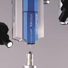
4 Multi-Probe Versatility Enriches the Functionality of Vision Measurement According to Individual Customer s Needs Touch Trigger Probe Quick Vision Series models can also use touch-trigger probes to support measurement of workpiece features that cannot be inspected with vision alone. This capability is also useful when the most precise height measurements are required. Magnified Vision A magnified image is taken by a CCD camera, and then dimensional measurements can be performed by way of edge detection and auto focus, which use image processing technology. Laser Probe Utilizing this non-contact displacement sensor that uses a laser focusing point method, the Quick Vision Series can use its scanning function to measure very small steps and curved planes at high speed. CPS Probe Thanks to its wavelength confocal format, non-contact displacement sensor that uses the epaxial chromatic aberration of the white light source, the Quick Vision Series can use its scanning function to measure very small steps and curved planes at high speed. TTL Laser AF Due to the coaxial laser focus that uses the double pinhole method and has low directivity, the Quick Vision Series is suited to high-speed height measurements. 4


5 UMAP Probe By using an extremely small stylus with a high aspect ratio, made possible by our proprietary sensing technology, the Quick Vision Series can perform contact measurements on small or narrow parts. Image edge detection using a filter Highly accurate height measurement thanks to image auto focus Measurement of a fuel injection nozzle hole s shape White Light Interferometer Using its white light interferometer, the Quick Vision Series can perform highly accurate 3D measurements in microscopic areas for surface analysis, small-diameter hole depth, and line and space measurements on circuit boards. Measurement of a lens barrel s shape Imaging optical head WLI optical head Metal Resin Points From Focus Contrast information can be used to obtain 3D-form data from images at different heights that have been taken by the Quick Vision Series. QV Index Using the QV index to rotate the workpiece makes it possible to automatically measure multiple surfaces without having to dismount/ remount the workpiece. 5


6 Main Unit Structure Enables High Accuracy and High-Performance 3D Non-Contact Measurements Quick Vision Series Features The Quick Vision Series is a non-contact dimension measurement system. It uses its CCD camera to take images magnified by its optical lens, and then uses image processing technology to detect the edges of the workpiece. The dimensions of microscopic features can be measured because the Quick Vision Series performs measurements on images that have been highly magnified by its optical system. The Quick Vision Series is extremely well suited to measurements of microscopic workpieces such as are found in electronics, semiconductor components, precision machinery, and medical equipment components. Because the Quick Vision Series performs non-contact measurements, there is no risk of the workpiece being damaged, deformed, or stained. In addition to measurements of electronic and semiconductor components that must be kept clean, the Quick Vision Series is also suited to measurements of workpieces such as soft resin-molded products and thin press-molded products. The Quick Vision Series can perform high-speed measurements of multiple points from within the captured image. The image processing technology and high-speed stage control enable high-throughput measurements, which makes the Quick Vision Series the optimal solution for workpieces that have many features to be measured and for manufacturing process management of mass-produced products. The Quick Vision Series uses its image auto focus function and non-contact displacement sensor to perform highly accurate height measurements. Main Unit Structure Optimized for Highly Accurate Measurements Structural deformation caused by movement along each axis has been minimized, which ensures that the Quick Vision Series can be used to perform highly accurate measurements with minimal spatial coordinate distortions. Lineup Offers Choice of Measuring Range and Accuracy The QV Series consists of a diverse lineup that includes models ranging from compact to large-range models and from models with general-purpose accuracy to models with extremely high accuracy. The QV Series can meet all the varied measurement needs for manufacturing industry. Highly Functional and Versatile Illumination Unit Vision measuring machine Contact-type measuring machine FEM structure analysis simulation Name Size Measurement range(mm) QV ELF QV Apex Hyper QV QV STREAM PLUS QV ACCEL QV-PROs use LEDs for all of their light sources: contour, surface, and programmable ring light. Lighting uniformity has been achieved at a high level, which leads to excellent part program compatibility between multiple QVs. LED light sources have excellent responsiveness, which improves measurement throughput. LED light sources have longer lives than halogen types, which reduces illumination fluctuations and thereby minimizes any errors caused by changes in light intensity. Vertical surface illumination Programmable ring light illumination Contour illumination Vertical surface illumination Programmable ring light illumination Stage surface Contour illumination 6


7 Highly Functional Lighting Supports Positive Edge Detection and Automatic Measurements Programmable Ring Light (PRL) Changing the positions of the two curved mirrors sets the ring light's obliquity to any chosen value between 30 and 80. This is effective for enhancing the edges of inclined surfaces or very small steps. Furthermore, the PRL light's illumination can be controlled independently in every direction, front and back, right and left. This makes it possible to configure highly variable lighting settings to match measurement locations. Measuring the top and bottom widths of metallization patterns on an IC package Objective lens PRL illumination Four-quadrant LED light Parabolic mirror Toroidal mirror Objective lens Uniform illumination can be obtained from the four-quadrant LEDs, whose brightness is independently controllable. Workpiece top face Obliquity can be set by controlling the positions of the two types of mirrors that move independently of the Z-Axis. Front Left Right Back Front Left Right Back RGB Color LED Illumination Changing the illumination color between red, green, blue, and white allows for the detection of edges that were not able to be used with conventional white light. Color LED usage example: Resist aperture dimensions on a printed circuit board Resist aperture dimension Resist Edge enhancement 7


 12.")


8 Powerful Vision Sensor with High Flexibility due to Mitutoyo s High Performance Lenses Programmable Power Turret The QV's programmable power turret has excellent magnifi cation repeatability which makes it suited to highly accurate measurements. Furthermore, the rich lineup of objectives contains lenses with magnifications ranging from 0.5X to 25X, which makes it possible to select the optimal optical system to match the measurement target. It is easy to install new objective lenses by using the optional calibration chart and compensation chart, so additional objectives can be purchased at a later date. Objective lenses QV-HR1X QV-HR2.5X PPT1X Field of View: mm PPT1X Field of View: mm QV-5X PPT1X Field of View: mm QV-HR10X PPT1X Field of View: mm PPT2X Field of View: mm PPT2X Field of View: mm PPT2X Field of View: mm PPT2X Field of View: mm PPT6X Field of View: mm PPT6X Field of View: mm PPT6X Field of View: mm PPT6X Field of View: mm PRO model programmable power turret Various objective lenses for the QVs Monitor magnification* 1 15X 29X 58X 72X 87X 144X 173X 290X 430X 580X 720X 870X 1440X 1730X 4300X Field of View (mm) objective lens 1 objective lens 2.5 objective lens 5 objective lens 10 objective lens* 2 25 objective lens* 2 *1: With QVPAK version 10 or later, the size of the video window can be changed. Monitor magnification shown in the above table is a reference value at the same display magnification when using 22-inch wide LCD monitor. *2: When the 10 objective lens or 25 objective lens is used in combination with the 2X or 6X magnification of the power turret, the brightness may be insufficient depending on the workpiece. *3: For the PRO3 models, the monitor magnifications are 1.34 times and the field of view are approximately 0.75 times those of the PRO model. Color Camera Specifications That Improve The Observation Function (PRO3 Model) To improve the observation function, Mitutoyo offers the PRO3 model that is equipped with a color CCD camera. A high-resolution CCD camera has been used to achieve the specifications of the PRO3, so highly accurate measurements, in which there is no decrease in the resolution of the screen, can be performed. Printed circuit board QFP package leads IC package LCD color filter Resin-molded product 8


 for measurement and conforms to the provisions of class 1 (visible light) of JIS C 6802 \"Safety of laser products.")
9 High-Performance Multi-Auto Focus The QV Series is equipped with a high-performance image auto focus function as standard. Image auto focus is used to guarantee accuracy. Thanks to the availability of various auto focus tools, the optimal focus for each surface texture and measured feature can be selected, which makes it possible to perform highly reliable height measurements. Furthermore, auto focus operates at high speed, which increases total measurement throughput. Surface focus Image auto focus can be used to measure the height of a chosen area, which makes it possible to perform stable height measurements that are minimally affected by the roughness of machined surfaces and other similar surfaces. Pattern focus Auto focus can be performed on lowcontrast transparent objects, such as film, glass and mirrored surfaces by projecting onto the object surface a pattern placed within the light path. Edge focus Edge focus is suited to focusing edges that have been chamfered or that have a corner radius. Using this focus tool prior to performing edge detection improves edge detection reproducibility. Multi-point auto focus Multi-point auto focus can be used to set multiple focus positions, sizes, and angles to arbitrary values. This tool can be used to obtain multiple sets of height information with a single focus operation, which makes it possible to perform highly efficient height and flatness measurements. Resin-molded product IC package Chamfered part of a machined surface Laser auto focus (LAF) Mitutoyo offers models that feature the LAF system, a system that enables highspeed focusing. CLASS 1 LASER PRODUCT Safety Precautions for the Laser Beam Used by the Laser Auto Focus Function (Models with the LAF Specification) This model uses a low-output visible laser beam (690 nm) for measurement and conforms to the provisions of class 1 (visible light) of JIS C 6802 "Safety of laser products." A class 1 laser warning and description label, like the one shown above, is attached to the main unit. Capable of Supporting ISO Guaranteed Accuracy Some models in the Quick Vision Series support the ISO guaranteed accuracy specifications. Contact Mitutoyo for details on applicable models. Guaranteed accuracies Length measurement error EU,MPE Probing error PF2D,MPE Length measurement error E Multi-Function Control Box This multi-function control box has been developed for maximum ease of use. Variable speed control Emergency-stop button 4-digit status LED 9

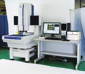
10 Compact CNC Vision Measuring System QV ELF QV ELF The edge detection capability and the functions of measurement software QVPAK are as powerful as those of the higher model QV Apex, which enables the QV ELF to surpass the conventional image of a compact model. While the QV ELF is a compact model, it has a more than adequate Z-Axis stroke of 200 mm. QV ELF Each lighting unit employs long-life white LEDs that have low power consumption. The LED light sources have excellent responsiveness, which improves measurement throughput. Mitutoyo offers models that are equipped with laser auto focus. This model can support ISO :2011 guaranteed accuracy (specifications on request). Specifications Model QV ELF Series Optical system PRO LAF LAF Order No Measuring range (X Y Z) mm Observation Unit PPT1X -2X -6X Resolution of scale / Scale type 0.1μm / Linear Encoder Imaging Device B&W CCD Co-axial Light White LED Illumination Unit Transmitted Light White LED PRL White LED Accuracy* 1 E1X, E1Y (2+3L/1000)μm E1Z (3+5L/1000)μm LAF Repeatability* 2 =0.4μm Operating temperature range 20±1 C Stage glass size mm Maximum stage loading * 3 15kg Main unit external dimensions mm Main unit mass (including the sub-base) 270kg *1 Determined by Mitutoyo's inspection method. L is the measured length (mm). The optical condition for accuracy assurance is to be (QV-HR2.5X or QV-SL2.5X) + Middle magnification of the tube lens. *2 LAF-equipped models only. *3 An excessively biased or concentrated load is excluded. 10


 can support ISO10360-7:2011 guaranteed accuracy (specifications on request).")
11 Standard CNC Vision Measuring System QV Apex QV Apex QV Series standard models range in size from compact to large. The PRO models achieve highly accurate measurements and are equipped with a programmable power turret, RGB color LED illumination, and a programmable ring light as standard. Mitutoyo offers models that are equipped with laser auto focus. The lineup, including the PRO3 models equipped with a color CCD camera, can satisfy a wide range of needs. QV Apex 302PRO The QV Apex404 and QV Apex606 X-Axis and Y-Axis drive speeds reach 400 mm/second. This greatly contributes to throughput improvement, particularly for workpieces that involve a large range of travel. This model (PRO type only) can support ISO :2011 guaranteed accuracy (specifications on request). Specifications Model QV Apex 302 QV Apex 404 QV Apex 606 Optical system PRO PRO3 PRO PRO3 PRO PRO3 LAF LAF LAF LAF LAF LAF LAF Order No Measuring range (X Y Z) mm mm 600x650x250mm Observation Unit PPT1X-2X-6X Resolution of scale / Scale type 0.1μm/Linear Encoder Imaging Device B&W CCD 3CCD Color B&W CCD 3CCD Color B&W CCD 3CCD Color Co-axial light Color LED Halogen Color LED Halogen Color LED Halogen Illumination Unit Transmitted Light White LED Halogen White LED Halogen White LED Halogen PRL Color LED Halogen Color LED Halogen Color LED Halogen Accuracy* 1 E1Z (1.5+4L/1000)μm E1X, E1Y (1.5+3L/1000)μm E2XY (2+4L/1000)μm LAF Repeatability* 2 =0.4μm =0.4μm =0.4μm =0.4μm =0.4μm =0.4μm Operating temperature range 20±1 C Stage glass size mm mm mm Maximum stage loading* 3 20kg 40kg 50kg Main unit external dimensions mm mm mm Main unit mass (including the sub-base) 360kg 579kg 1450kg *1 Determined by Mitutoyo's inspection method. L is the measured length (mm). The optical condition for accuracy assurance is to be (QV-HR2.5X or QV-SL2.5X) + Middle magnifi cation of the tube lens. *2 LAF-equipped models only. *3 An excessively biased or concentrated load is excluded. 11


12 High-accuracy CNC Vision Measuring System Hyper QV Hyper QV The Hyper QV is a highly accurate model that is equipped with a high-resolution/accuracy scale. A lineup, similar to the QV Apex, containing models that range in size from compact to large means that a model ideally suited to the size of the workpiece can be selected. This model achieves highly accurate measurements and is equipped with a programmable power turret, RGB color LED illumination, and a programmable ring light as standard. Hyper QV 404PRO This model is standard-equipped with an automatic temperature compensation function that uses a temperature sensor on the main unit of the measuring machine and a temperature sensor for the workpiece, thus guaranteeing the stated accuracy specification applies over the temperature range 18 to 23 C for stable measurement results. This model can support ISO :2011 guaranteed accuracy (specifications on request). Specifications Model Hyper QV 302 Hyper QV 404 Hyper QV 606 Optical system PRO LAF LAF LAF LAF Order No Measuring range (X Y Z) mm mm mm Observation Unit PPT1X-2X-6X Resolution of scale / Scale type 0.02μm/Linear Encoder Imaging Device B&W CCD Co-axial light Color LED Illumination Unit Transmitted Light White LED PRL Color LED Accuracy * 1 E1Z (1.5+2L/1000)μm E1X, E1Y (0.8+2L/1000)μm E2XY (1.4+3L/1000)μm LAF repeatability* 2 =0.4μm =0.4μm =0.4μm Operating temperature range 18 ~ 23 C Stage glass size mm mm mm Maximum stage loading * 3 15kg 30kg 40kg Main unit external dimensions mm mm mm Main unit mass (including the sub-base) 360kg 579kg 1450kg Temperature compensation function Automatic *1 Determined by Mitutoyo's inspection method. L is the measured length (mm). The optical condition for accuracy assurance is to be (QV-HR2.5X or QV-SL2.5X) + Middle magnification of the tube lens. *2 LAF-equipped models only. *3 An excessively biased or concentrated load is excluded. 12

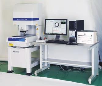
13 Non-stop CNC Vision Measuring System QV STREAM PLUS QV STREAM PLUS QV STREAM PLUS 606PRO The QV STREAM PLUS is an innovative vision measuring machine that acquires images without stopping the stage. This is accomplished by synchronizing the main unit's X-Axis and Y-Axis traversal with the strobe illumination. Conventional vision measuring machines repeat the displacement, stop, measurement, and displacement cycle, which hinders the improvement of throughput. In contrast, the QV STREAM PLUS realizes non-stop vision measurement (stream mode) by eliminating acceleration, deceleration, and stop times. Consequently, this dramatically reduces the overall measurement time needed. Specifications A lineup, similar to the QV Apex, and containing models that range in size from compact to large, means that a model ideally suited to the size of the workpiece can be selected. Displacement Imaging Displacement Imaging Displacement Imaging Completion of imaging Batch measurement Camera Continuous displacement Camera Model QV STREAM PLUS 302 QV STREAM PLUS 404 QV STREAM PLUS 606 Optical system PRO LAF LAF LAF LAF Order No Measuring range (X Y Z) mm mm mm Observation Unit PPT1X-2X-6X Resolution of scale / Scale type 0.1μm/Linear Encoder Imaging Device B&W CCD Co-axial light* 2 Color LED Illumination Unit* 1 Transmitted Light Blue LED PRL* 2 Color LED Accuracy* 3 E1Z (1.5+4L/1000)μm E1X, E1Y (1.5+3L/1000)μm E2XY (2+4L/1000)μm LAF repeatability =0.4μm =0.4μm =0.4μm Operating temperature range 20±1 C Stage glass size mm mm mm Maximum stage loading * 4 20kg 40kg 50kg Main unit external dimensions mm mm mm Main unit mass (including the sub-base) 360kg 579kg 1450kg *1 Only one of the illumination functions (reflected, transmitted, and PRL illumination) can be set in STREAM mode. The 4-way PRL illumination can be set to the entire lighting (4-direction lighting) or single-direction lighting. *2 Enable to use cyan only while using STREAM mode. *3 Determined by Mitutoyo s inspection method. L is the measured length (mm). The optical condition for accuracy assurance is to be (QV-HR2.5X or QV-SL2.5X) + Middle magnification of the tube lens. *4 An excessively biased or concentrated load is excluded. 13


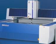
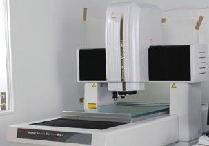
14 Large CNC Vision Measuring System QV ACCEL QV ACCEL 1212PRO QV ACCEL The QV ACCEL is a moving-bridge type. Because the stage remains stationary, the fixtures used to hold workpieces in place can be simplified. This leads to a reduction in the amount of work required to create these fixtures. In addition, the QV ACCEL is suited to measurements of workpieces that have short life cycles and to measurements of thin and light-weight workpieces. The QV ACCEL is optimal for measurements of printed circuit boards, whose density and resolution continue to increase, as well as metal masks and screen plates. The QV ACCEL is also optimal for measurements on glass circuit boards, film, and other components of display panels. By using highly functional edge detection and image auto focus, the QV ACCEL can perform highly accurate height measurements. The QV ACCEL is standard-equipped with a pattern focus function that can be used to perform image auto focusing even on transparent objects such as film and glass. Mitutoyo offers models that are equipped with laser auto focus. Model QV ACCEL 808 QV ACCEL 1010 QV ACCEL 1212 QV ACCEL 1517 Optical system PRO PRO3 PRO PRO3 PRO PRO3 PRO PRO3 Standard Machine LAF-equipped Machine Measuring range (X Y Z) mm mm mm mm Observation Unit PPT1X-2X-6X Resolution of scale / Scale type 0.1μm/Linear Encoder Imaging Device B&W CCD Color CCD B&W CCD Color CCD B&W CCD Color CCD B&W CCD Color CCD Illumination Unit QV ACCEL 808PRO Specifications Co-axial light Color LED Halogen Color LED Halogen Color LED Halogen Color LED Halogen Transmitted Light White LED Halogen White LED Halogen White LED Halogen White LED Halogen PRL Color LED Halogen Color LED Halogen Color LED Halogen Color LED Halogen Accuracy* 1 E1Z (1.5+4L/1000)μm (2.5+5L/1000)μm E1X, E1Y (1.5+3L/1000)μm (2.2+3L/1000)μm E2XY (2.5+4L/1000)μm (3.5+4L/1000)μm Repeatability* 1 Short dimension XY 3 =0.2μm Long dimension axis 3 =0.7μm 3 =1.5μm LAF repeatability* 2 =0.4μm Operating temperature range 20±1 C Stage glass size mm mm mm mm Maximum stage loading* 3 10kg 30kg 30kg 30kg Main unit external dimensions mm mm mm mm Main unit mass (not including the sub-base) 2050kg 2950kg 3600kg 4500kg *1 Determined by Mitutoyo's inspection method. L is the measured length (mm). The optical condition for accuracy assurance is to be (QV-HR2.5X or QV-SL2.5X) + Low magnification of the tube lens. *2 LAF-equipped models only. *3 An excessively biased or concentrated load is excluded. 14
μm.")


15 Ultra-high Accuracy CNC Vision Measuring System ULTRA QV 404 ULTRA QV 404 The ULTRA QV 404 is an ultra-precise CNC vision measuring machine that achieves measurement accuracy of E1XY: ( L/1000)μm. To improve the maneuverability of each axis, Mitutoyo has employed aerostatic bearings, which Mitutoyo developed in our highly accurate 3D measuring machines, as the guidance systems for the X-, Y-, and Z-axes. Specifications ULTRA QV 404PRO This model is standard-equipped with an automatic temperature compensation function that uses a temperature sensor on the main unit of the measuring machine and a temperature sensor for the workpiece, thus guaranteeing the stated accuracy specification applies over the temperature range 19 to 23 C for stable measurement results. This model can support ISO :2011 guaranteed accuracy (specifications on request). Accuracy* 1 Model ULTRA QV 404 Optical system PRO LAF LAF Order No Measuring range (X Y Z) mm Observation Unit PPT1X-2X-6X Resolution of scale / Scale type 0.01μm / Linear Encoder Imaging Device B&W CCD Co-axial light Halogen Illumination Unit Transmitted Light Halogen PRL Halogen E1Z (50mm stroke)* 2 (1+2L/1000)μm E1Z (Full stroke) (1.5+2L/1000)μm E1X, E1Y (0.25+L/1000)μm E2XY (0.5+2L/1000)μm On-screen repeatability 3 =0.2μm Auto focus repeatability =0.4μm LAF Repeatability =0.4μm Operating temperature range 19 ~ 23 C Stage glass size mm Maximum stage loading * 3 40kg Main unit external dimensions mm Main unit mass (including the sub-base) 2150kg Operating air pressure 0.4 MPa* 4 Required air flow rate 300L/min(ANR)* 5 Temperature compensation function Automatic *1 Determined by Mitutoyo's inspection method. L is the measured length (mm). The optical condition for accuracy assurance is to be QV-5X + Middle magnifi cation of the tube lens. *2 Verifi ed at shipment from factory. *3 An excessively biased or concentrated load is excluded. *4 Air supply pressure to be in range MPa. *5 Indicates the fl ow rate under normal conditions. 15


16 CNC Vision Measuring System equipped with a Touch Trigger Probe QV TP QVTP Apex 302PRO QV Touch Trigger Probe The QVTP Series enables non-contact measurements and contact measurements on the same machine. The QVTP Series has a vision measurement function and can also perform contact measurements by way of its touch trigger probe. The QVTP Series can support measurements of 3D workpieces. The QVTP Series can perform 3D measurements of workpieces, such as press-molded products, resin-molded products, and machined products, that could not be measured with conventional image processing alone. The QV TP Series is equipped with a probe module change rack. Using the probe module change rack makes it possible to switch between vision measurement and touch trigger probe measurement during a sequence of automatic measurements. Furthermore, storing the characteristics of different styli makes it possible to perform measurements on multiple surfaces. This model (excluding QV ACCEL type) can support ISO :2011 guaranteed accuracy (specifications on request). Specifications QVTP ELF Model QVTP ELF Series Optical system PRO LAF LAF Order No Measuring range by vision probe* 3 (X Y Z) mm Measuring range by touch probe* 3 (X Y Z) mm Observation Unit PPT1X-2X-6X Resolution of scale / Scale type 0.1μm / Linear Encoder Imaging Device B&W CCD Co-axial Light White LED Illumination Unit Transmitted Light White LED PRL White LED Measuring Accuracy* 1 E1X, E1Y (2+3L/1000)μm (Vision) E1Z (3+5L/1000)μm TP measuring accuracy* 1 E1X, E1Y, E1Z (2.4+3L/1000)μm LAF Repeatability =0.4μm Operating temperature range 18 ~ 23 C Stage glass size mm Maximum stage loading * 2 15kg Main unit external dimensions mm Main unit mass (including the sub-base) 270kg Temperature compensation function Manual *1 Determined by Mitutoyo's inspection method. L is the measured length (mm). The optical condition for accuracy assurance is to be (QV-HR2.5X or QV-SL2.5X) + Middle magnification of the tube lens. *2 An excessively biased or concentrated load is excluded. *3 Measuring range is smaller than the dimension in the specifications table above when the machine is equipped with module change rack, master ball and calibration ring. 16
17 Specifications QVTP Apex Model QVTP Apex 302 QVTP Apex 404 QVTP Apex 606 Optical system PRO PRO3 PRO PRO3 PRO PRO3 Standard machine LAF-equipped machine Measuring range by vision probe* 1 (X Y Z) mm mm mm Measuring range by touch probe* 1 (X Y Z) mm mm mm Observation unit PPT1X-2X-6X Resolution of scale / Scale type 0.1μm/Linear Encoder Imaging Device B&W CCD 3CCD Color B&W CCD 3CCD Color B&W CCD 3CCD Color Co-axial light Color LED Halogen Color LED Halogen Color LED Halogen Illumination Unit Transmitted Light White LED Halogen White LED Halogen White LED Halogen PRL Color LED Halogen Color LED Halogen Color LED Halogen Measuring Accuracy* 2 E1X, E1Y (1.5+3L/1000)μm E1Z (1.5+4L/1000)µm (Vision) E2XY (2+4L/1000)µm TP measuring accuracy* 2 E1X, E1Y, E1Z (1.8+3L/1000)μm LAF repeatability* 3 =0.4μm Operating temperature range 18 ~ 23 C Stage glass size mm mm mm Maximum stage loading* 4 20kg 40kg 50kg Main unit external dimensions mm mm mm Main unit mass (including the sub-base) 360kg 579kg 1450kg Temperature compensation function Manual *1 Measuring range is smaller than the dimension in the specifications table above when the machine is equipped with module change rack, master ball and calibration ring. *2 Determined by Mitutoyo's inspection method. L is the measured length (mm). The optical condition for accuracy assurance is to be (QV HR2.5X or QV SL2.5X) + Middle magnification of the tube lens. *3 LAF-equipped models only. *4 An excessively biased or concentrated load is excluded. Hyper QVTP Model Hyper QVTP302 Hyper QVTP404 Hyper QVTP606 Optical system PRO LAF LAF LAF LAF Order No Resolution of scale / Scale type 0.02μm/Linear Encoder Measuring Accuracy* 1 E1X, E1Y (0.8+2L/1000)μm E1Z (1.5+2L/1000)μm (Vision) E2XY (1.4+3L/1000)μm TP measuring accuracy* 1 E1X, E1Y, E1Z (1.7+3L/1000)μm LAF repeatability =0.4μm =0.4μm =0.4μm Operating temperature range 18 ~ 23 C Maximum stage loading* 2 15kg 30kg 40kg Temperature compensation function Automatic *1 Determined by Mitutoyo's inspection method. L is the measured length (mm). The optical condition for accuracy assurance is to be (QV HR2.5X or QV SL2.5X) + Middle magnification of the tube lens. *2 An excessively biased or concentrated load is excluded. Note: For other specifications, refer to QVTP Apex. QVTP ACCEL Model QVTP ACCEL 808 QVTP ACCEL 1010 QVTP ACCEL 1212 QVTP ACCEL 1517 Optical system PRO PRO3 PRO PRO3 PRO PRO3 PRO PRO3 Order No Measuring range by vision probe* 2 (X Y Z) mm mm mm mm Measuring range by touch probe* 2 (X Y Z) mm mm mm mm Measuring Accuracy* 1 E1X, E1Y (1.5+3L/1000)μm (2.2+3L/1000)μm E1Z (1.5+4L/1000)μm (2.5+5L/1000)μm (Vision) E2XY (2.5+4L/1000)μm (3.5+4L/1000)μm TP measuring accuracy* 1 E1X, E1Y, E1Z (1.8+3L/1000)μm (3+4L/1000)μm (6+7L/1000)μm Repeatability* 1 Short dimension XY 3 =0.2μm Long dimension axis 3 =0.7μm 3 =1.5μm Operating temperature range 20±1 C *1 Determined by Mitutoyo's inspection method. L is the measured length (mm). The optical condition for accuracy assurance is to be (QV-HR2.5X or QV-SL2.5X) + Low magnification of the tube lens. *2 Measuring range is smaller than the dimension in the specifications table above when the machine is equipped with module change rack, master ball and calibration ring. Note: For other specifications, refer to QV ACCEL. NOTE: Machines in this series are equipped with the main unit deactivating system (relocation detection system) that prevents the machine from operating if it is subjected to an unexpected vibration or if it is relocated. Be sure to contact your nearest Mitutoyo sales office prior to relocating this machine after initial installation. 17


18 Non-contact Laser Probe-equipped CNC Vision Measuring System QV HYBRID TYPE1 QV HYBRID TYPE 1 Hyper QVH1 404PRO The QV HYBRID TYPE1 is a hybrid measuring machine that has a vision measurement function and can use the scanning function of its non-contact displacement sensor to measure very small steps and curved surfaces at high speeds. Mitutoyo's proprietary double-pinhole technique is used for the displacement sensor's detection method. Compared to the knife-edge and triangulation techniques, this method has the advantage of lower laser directivity. Because a focusing point method is used, the QV HYBRID TYPE1 has the advantage that it is minimally affected by factors such as the color of the workpiece. The small laser spot diameter of approximately 2μm makes it possible to perform measurements with high horizontal resolution. The displacement sensor alone has a wide measuring range of ±0.5 mm, which makes it possible to perform form measurements with a wide dynamic range. For displacements outside this range, scanning can be performed by moving the Z axis. This model (excluding QV ACCEL and QV STREAM PLUS type) can support ISO :2011 guaranteed accuracy (specifications on request). Semiconductor laser Beam splitters Collimating lens Photodiode B Pinhole (front) Pinhole (rear) Photodiode A Scale and lens drive Applications Viewer Function The QV HYBRID series is provided as standard with the viewer function that allows you to easily set filter parameters and calculation items for laser scanning measurement while visual inspection is in progress. Workpiece: Printed circuit board Objective lens Prior confirmation with Viewer Profile assessment analysis with FORMPAK-QV A Variety of Laser Scanning Tools A variety of scanning tools including line, cross, circle, and area are provided as standard for both Type 1 and 4. Form analysis with FORMTRACEPAK-PRO QV TraceMaker 7000 Area Trace Route Creation from Image This tool can create a trace route from a captured image. It is appropriate for measurement of complicated areas. 18
19 Specifications QV Apex HYBRID TYPE1 Model QVH1 Apex 302 QVH1 Apex 404 QVH1 Apex 606 Optical system PRO PRO3 PRO PRO3 PRO PRO3 Order No Measuring range by vision probe (X Y Z) mm mm mm Measuring range by displacement sensor (X Y Z) mm mm mm Resolution of scale / Scale type 0.1μm / Linear Encoder Observation Unit PPT1X-2X-6X Imaging Device B&W CCD 3 CCD Color B&W CCD 3 CCD Color B&W CCD 3 CCD Color Co-axial Light Color LED Halogen Color LED Halogen Color LED Halogen Illumination unit Transmitted Light White LED Halogen White LED Halogen White LED Halogen PRL Color LED Halogen Color LED Halogen Color LED Halogen Measuring Accuracy* 1 (Vision) E1X,E1Y E1Z E2XY QV ACCEL HYBRID TYPE1 Model QVH1 ACCEL 808 QVH1 ACCEL 1010 QVH1 ACCEL 1212 QVH1 ACCEL 1517 Optical system PRO PRO3 PRO PRO3 PRO PRO3 PRO PRO3 Order No Measuring range by vision probe (X Y Z) mm mm mm mm Measuring range by displacement sensor (X Y Z) mm mm mm mm Measuring Accuracy* 1 E1X,E1Y (1.5+3L/1000)µm (2.2+3L/1000)µm E1Z (1.5+4L/1000)µm (2.5+5L/1000)µm (Vision) E2XY (2.5+4L/1000)µm (3.5+4L/1000)µm Displacement sensor Measuring Accuracy* 1 E1Z (2.5+4L/1000)µm (3.5+5L/1000)µm Detecting range of probe itself ±0.5mm Spot diameter About ø2µm Displacement sensor Working distance including collision preventing device) 5mm Operating Temperature range 20±1 C *1 Determined by Mitutoyo s inspection method. L is the measured length (mm). The optical condition for accuracy assurance is to be (QV-HR2.5X or QV-SL2.5X) + Low magnification of the tube lens. Other specifications are the same as those of the QV ACCEL. For details, refer to page (1.5+3L/1000)µm (1.5+4L/1000)µm (2+4L/1000)µm (1.5+4L/1000)µm ±0.5mm About ø2µm Displacement sensor Measuring Accuracy* 1 E1Z Detecting range of probe itself Spot diameter Displacement sensor Working distance including collision preventing device) 5mm Operating Temperature range 20±1 C Stage glass size mm mm mm Maximum stage loading* 2 20kg 40kg 50kg Main unit external dimensions mm mm mm Main unit mass (including the sub-base) 370kg 589kg 1460kg *1 Determined by Mitutoyo s inspection method. L is the measured length (mm). The optical condition for accuracy assurance is to be (QV-HR2.5X or QV-SL2.5X) + Middle magnification of the tube lens. *2 An excessively biased or concentrated load is excluded. Hyper QV HYBRID TYPE 1 Model Hyper QVH1 302 Hyper QVH1 404 Hyper QVH1 606 Optical system PRO PRO PRO Order No Resolution of scale / Scale type 0.02μm / Linear Encoder Measuring Accuracy* 1 E1X,E1Y (0.8+2L/1000)µm E1Z (1.5+2L/1000)µm (Vision) E2XY (1.4+3L/1000)µm Displacement sensor Measuring Accuracy* 1 E1Z (1.5+2L/1000)µm Operating Temperature range C Temperature Compensation function Automatic Maximum stage loading* 2 15kg 30kg 40kg *1 Determined by Mitutoyo s inspection method. L is the measured length (mm). The optical condition for accuracy assurance is to be (QV-HR2.5X or QV-SL2.5X) + Middle magnification of the tube lens. *2 An excessively biased or concentrated load is excluded. Other specifications are the same as those of the QVH1 Apex. For details, refer to above table. QV STREAM PLUS HYBRID TYPE1 Model QVH1 STREAM 302 QVH1 STREAM 404 QVH1 STREAM 606 Optical system PRO PRO PRO Order No Imaging Device B&W CCD Co-axial Light Color LED Illumination unit Transmitted Light Blue LED PRL Color LED Measuring Accuracy* 1 E1X,E1Y (1.5+3L/1000)µm E1Z (1.5+4L/1000)µm (Vision) E2XY (2+4L/1000)µm Displacement sensor Measuring Accuracy* 1 E1Z (1.5+4L/1000)µm Operating Temperature range 20±1 C *1 Determined by Mitutoyo s inspection method. L is the measured length (mm). The optical condition for accuracy assurance is to be (QV-HR2.5X or QV-SL2.5X) + Middle magnification of the tube lens. Other specifications are the same as those of the QVH1 Apex. For details, refer to above table. NOTE: Machines in this series are equipped with the main unit deactivating system (relocation detection system) that prevents the machine from operating if it is subjected to an unexpected vibration or if it is relocated. Be sure to contact your nearest Mitutoyo sales office prior to relocating this machine after initial installation. CLASS 1 LASER PRODUCT Safety Precautions for Laser Beam These systems uses a low-power invisible laser beam (780nm) which corresponds to Class 1 (invisible light) of JIS C 6802 "Safety Standard of Laser Radiation Products". The class 1 laser warning label as shown above is attached to the main unit.


20 CNC Vision Measuring System equipped with Non-contact Scanning Sensor QV HYBRID TYPE4 QV HYBRID TYPE4 Hyper QVH4 606PRO QV HYBRID TYPE 4 is equipped with CPS (Chromatic Point Sensor) that employs confocal method. This method uses the axial chromatic aberration to detect Z axis direction position. The QV HYBRID TYPE4 is a hybrid measuring machine that has a vision measurement function and can use the scanning function of its non-contact displacement sensor to measure very small steps and curved surfaces at high speeds. The displacement sensor detection method employs the wavelength confocal method that uses the axial chromatic aberration of the white light source. The sensor itself has a wide measuring range and has a high inclined-surface-following performance for both mirrored and diffusive surfaces. This system uses LEDs as light sources. Thanks to Auto-brightness control, the sensor makes it possible to perform measurements that are minimally affected by reflectivity variations on the workpiece. The heights of two surfaces within the measuring range can be detected simultaneously, which makes it possible to support measurements of the thickness of thin, transparent objects. This model can support ISO :2011 guaranteed accuracy (specifications on request). Measurement principle 20


21 Scanning measurement with automatic movement of the Z axis FORMTRACEPAK-PRO Analysis Example CPS probe Color-coded 3D display Specifications QV Apex HYBRID TYPE 4 Model QVH4 Apex 302 Shaded display QVH4 Apex 404 QVH4 Apex 606 Optical system PRO PRO PRO Order No Measuring range by vision probe (X Y Z) mm mm mm Measuring range by displacement sensor (X Y Z) mm mm mm Resolution of scale / Scale type 0.1μm / Linear Encoder Observation Unit PPT1X-2X-6X Imaging Device B&W CCD B&W CCD B&W CCD Co-axial Light Color LED Color LED Color LED Illumination unit Transmitted Light White LED White LED White LED PRL Color LED Color LED Color LED Measuring Accuracy* 1 E1X,E1Y (1.5+3L/1000)µm E1Z (1.5+4L/1000)µm (Vision) E2XY (2+4L/1000)µm Displacement sensor Accuracy E1Z (1.5+4L/1000)µm Detecting range of probe itself ±0.6mm Spot diameter About ø4µm Displacement sensor Working distance((including 21.0mm collision preventing device) Operating Temperature range 20±1 C Stage glass size mm mm mm Maximum stage loading* 2 20kg 40kg 50kg Main unit external dimensions mm mm mm Main unit mass (including the sub-base) 370kg 589kg 1460kg *1 Determined by Mitutoyo s inspection method. L is the measured length (mm). The optical condition for accuracy assurance is to be (QV-HR2.5X or QV-SL2.5X) + Middle magnification of the tube lens. *2 An excessively biased or concentrated load is excluded. Hyper QV HYBRID TYPE4 Model Hyper QVH4 302 Hyper QVH4 404 Hyper QVH4 606 Optical system PRO PRO PRO Order No Resolution of scale / Scale type 0.02μm / Linear Encoder Measuring Accuracy* 1 E1X,E1Y (0.8+2L/1000)µm E1Z (1.5+2L/1000)µm (Vision) E2XY (1.4+3L/1000)µm Displacement sensor Accuracy E1Z (1.5+2L/1000)µm Operating Temperature range 18~23 C Temperature compensation function Automatic Maximum stage loading* 2 15kg 30kg 40kg *1 Determined by Mitutoyo s inspection method. L is the measured length (mm). The optical condition for accuracy assurance is to be (QV-HR2.5X or QV-SL2.5X) + Middle magnification of the tube lens. *2 An excessively biased or concentrated load is excluded. Other specifications are the same as those of the QVH4 Apex.For details,refer to the table above. NOTE: Machines in this series are equipped with the main unit deactivating system (relocation detection system) that prevents the machine from operating if it is subjected to an unexpected vibration or if it is relocated. Be sure to contact your nearest Mitutoyo sales office prior to relocating this machine after initial installation. 21

, makes dimension measurements of microscopic forms possible.")
 300 200 200mm 400 400 200mm Effective measuring range on glass surface: 360 400 200 mm* 5 Effective measuring range (common between")

μm Optical condition for accuracy assurance QV-HR2.5X or QV-SL2.5X + Middle magnification tube lens QV-5X + Middle magnification tube lens UMAP E1X, E1Y (UMAP 110) * 3 (1.7+3L/1000)μm (1.")
22 Microscopic Form Measurement System UMAP Vision System TYPE2 Stylus lineup 0.2mm 2mm 5mm 10mm 16mm 15 m UMAP101 Stylus 30 m UMAP103 Stylus 70 m UMAP107 Stylus 100 m UMAP110 Stylus 300 m UMAP130 Stylus 15 m 30 m 70 m Measurement examples 100 m 300 m UMAP Vision System TYPE2 Measurement of the shape of the holes in a fuel injection nozzle Measurement of the shape of a lens barrel The UMAP Vision System uses Mitutoyo's proprietary sensing technology and is equipped with an ultra low-force probe. The utilization of extremely small styli with high aspect ratios (styli with a diameter between 15μm and 300μm), makes dimension measurements of microscopic forms possible. These measurements cannot be made using conventional contact measurement sensors. Specifications Model Hyper UMAP 302 ULTRA UMAP 404 Optical system PRO LAF LAF LAF Order No Measuring range (X Y Z) mm mm Effective measuring range on glass surface: mm* 5 Effective measuring range (common between images and UMAP103) mm mm Resolution of scale / Scale type 0.02μm/Linear Encoder 0.01μm/Linear Encoder Observation unit PPT1X-2X-6X Imaging Device B&W CCD Co-axial Light Color LED Halogen Illumination unit Transmitted Light White LED Halogen PRL Color LED Halogen E1X, E1Y (0.8+2L/1000)μm (0.25+L/1000)μm E1Z (50mm stroke)* 2 (1+2L/1000)μm Measuring accuracy* 1 Vision E1Z (full stroke) (1.5+2L/1000)μm (1.5+2L/1000)μm E2XY (1.4+3L/1000)μm (0.5+2L/1000)μm Optical condition for accuracy assurance QV-HR2.5X or QV-SL2.5X + Middle magnification tube lens QV-5X + Middle magnification tube lens UMAP E1X, E1Y (UMAP 110) * 3 (1.7+3L/1000)μm (1.5+3L/1000)μm UMAP repeatability* 1 UMAP101, 103, 107 =0.1μm =0.08μm UMAP110, 130 =0.15μm =0.12μm LAF repeatability* 1 =0.4μm =0.4μm Operating temperature range 18 ~ 23 C 19 ~ 23 C Maximum stage loading* 4 15kg 40kg Operating air pressure 0.4MPa Required air flow rate 300L/min (ANR) Temperature compensation function Automatic *1 Determined by Mitutoyo s inspection method. L is measured length (mm). *2 Verified at shipment from factory. *3 The UMAP accuracies are guaranteed when UMAP110 is used. *4 An excessively biased or concentrated load is excluded. *5 Effective measuring range when contour light is used. 22


23 Non-contact 3D Measuring System Hyper QV WLI Principle of WLI measurement White light is split into two beams, one for the reference mirror within the interference objective lens and the other for the measurement sample. When the interference objective lens is swept in the Z-direction, white interference fringes are generated only for the area of the measurement sample that is in focus. The 3D shape of the object being measured is calculated by detecting the peak position of the interference fringe intensity at each pixel position of the CCD camera. CCD camera Z-axis scan Interference fringes White light Beam splitter Reference mirror Interference objective lens Beam splitter Hyper QV WLI WLI optical system head Measurement target Measurement target Interference fringes and intensity depiction The Hyper Quick Vision WLI is Mitutoyo s leading, highly accurate dual-head measurement system equipped with a white light interferometer (WLI) optical head. Equipping a vision measuring machine with a WLI head makes it possible for the machine to perform measurements ranging from 2D coordinate and dimension measurements to highly accurate 3D measurements on microscopic areas in applications such as surface analysis, small-diameter hole depth, and circuit board wiring dimensions. Specifications Model Hyper QV WLI 302 Hyper QV WLI 404 Hyper QV WLI 606 Optical system PRO Order No WLI optical head unit Measuring range * 1 (X Y Z) mm mm mm Imaging Device B&W CCD Illumination Unit Co-axial Light Halogen Z-axis scanning range * 2 170μm Z-axis Repeatability 2 0.2μm Vision optical head unit Measurement range (X Y Z) mm mm mm Resolution of scale / Scale type 0.01μm / Linear Encoder Observation unit PPT 1X-2X-6X Imaging Device B&W CCD Co-axial Light Color LED Illumination Unit Transmitted Light While LED PRL Color LED E1X, E1Y (0.8 2L/1000)μm Measuring accuracy * 3 E1Z (1.5+2L/1000)μm E2XY (1.4+3L/1000)μm Operating Temperature range 20±0.3 C Stage glass size mm mm mm Maximum stage loading* 4 15kg 25kg 35kg Main unit external dimensions mm mm mm Main unit mass (including the sub-base) 490kg 1160kg 2275kg Operating air pressure 0.4Mpa *1 Movable range of WLI optical head. Three dimensional shape measurement using WLI is allowed within one field of vision. *2 In case of standard mode. Applicable to max. 200μm by modifying scan pitch. *3 Determined by Mitutoyo s inspection method. L is measured length (mm). The optical condition for accuracy assurance is to be (QV-HR2.5X or QV-SL2.5X) + Low magnification of the tube lens. *4 An excessively biased or concentrated load is excluded. 23
24 Dimensions QV302 Unit:mm Column 5-ø14 (Level adjusting bolt hole) Measuring range 19-M6 depth 12 (Jig mounting tapped hole) Column 200 (Measuring range) 300 (Measuring range) 464 (Dimension between columns) QV404 Column 8-ø14 (Level adjusting bolt hole) 24-M6 depth 12 (Jig mounting tapped hole) Column 400 (Measuring range) 400 (Measuring range) 580 (Dimension between columns) QV606 Column Measuring range 24-M6 depth 12 (Jig mounting tapped hole) 12-ø14 (Level adjusting bolt hole) Column 650 (Measuring range) 600 (Measuring range) 787 (Dimension between columns) For more information about dimensions of the PC table, please contact your local Mitutoyo sales office. 24
25 QV ACCEL Column Measuring range 40-M6 depth 12 (Jig mounting tapped hole) (Measuring range) 923 Column (Measuring Range) Unit:mm QV ACCEL Column Measuring range (Measuring range) Column (Measuring Range) Jig mounting rail 24-M6 (Jig mounting tapped hole) QV ACCEL Column Measuring range (Measuring range) Column (Measuring Range) Jig mounting rail 24-M6 (Setting position shifting type) 7.5 QV ACCEL For more information about dimensions of the PC table, please contact your local Mitutoyo sales office. Column Measuring range (Measuring range) Column (Measuring Range) Jig mounting rail 24-M6 (Setting position shifting type) 25
26 Dimensions ULTRA QV M Ø7 Column Measuring range Column Unit:mm QV ELF (10.5) (37) 280 (37) (10.5) (10.5) (17.5) 319 (17.5) 2-Glass fixing screw (10.5) 190 Column (21) (33) 18-M6 depth 12 5-ø level adjusting bolt (52) 250 (Measuring range) 312 (Stage glass set-in dimensions) (52) (Dimension between columns) (21) (33) Column (17.5) (61) (56) 200 (Measuring range) (56) 312 Dimensions in parentheses apply to LAF-equipped machines. For more information about dimensions of the PC table, please contact your local Mitutoyo sales office. 26
. * There are limitations on what functions can be used, depending the lens.")
27 Optional Hardware / Objective Lenses Calibration Chart and QV Compensation Chart Calibration chart A calibration chart is used to compensate for the pixel size of the CCD chip and for the auto focus accuracy and optical axis offset at each magnification of the variable magnification unit (PPT). * There are limitations on what functions can be used, depending the lens. For details, contact your Mitutoyo sales office. QV Index Consecutive measurements of the sides and bottom of a workpiece can be made without having to perform refixturing. This leads to a decrease in the production costs related to fi xturing, which results in an improvement in measurement efficiency. Supported models: QV302, 404, 606 Supported QVPAK versions: version or later RGB Color Filtering Unit A color filtering function can be added to the vertical surface illumination or programmable ring light illumination in Quick Vision models that use a halogen light source. This function enhances the visibility of low-reflection surfaces on colored workpieces, facilitating edge detection. This function can also be retrofitted to a conventional Quick Vision model. It is possible to switch between the three colors of the filter unit (red, green, and blue) from QVPAK. In addition, an optional yellow filter enables vision measurement in yellow rooms, which have high light sensitivity. Note: This is a dedicated option for PRO models with halogen illumination specifications. QV Objective Lenses 27 QV compensation chart* This glass chart is used to perform compensation for distortions within the screen caused by the optical system, and auto focus compensation, which reduces auto focus variations that are caused by differences between the workpiece pattern and texture. * There are limitations on what functions can be used, depending on the lens. For details, contact your Mitutoyo sales office. Item Specifi cations Maximum workpiece size ø140mm (Max) Maximum faceplate loading 2kg (Max) Resolution 0.1 Rotational positioning ±0.5 accuracy Rotational speed 10 r.p.m External dimensions (W D H) mm Using a red fi lter QV objective lenses Objective lens QV-SL0.5 * QV-HR1 QV-SL1 QV-HR2.5 QV-SL2.5 QV-5 QV-HR10 * QV-10 * QV-25 * Order No. 02AKT199 02AKT250 02ALA150 02AKT300 02ALA170 02ALA420 02AKT650 02ALG010 02ALG020 Optical magnification 0.5X 1X 2.5X 5X 10X 25X Working distance 30.5mm 40.6mm 52.5mm 40.6mm 60mm 33.5mm 20mm 30.5mm 13mm PRO model imaging FOV [ (H) mm (V) mm] PRO3 model imaging FOV [(H) mm (V) mm] Turret Turret Turret Turret Turret Turret * When the QV-SL0.5, QV-HR10, QV-10, or QV-25 objective lens is used, some limitations, such as the illumination being insufficient depending on the workpiece, may occur. Set of objective lenses that support PFF Objective Lens Sets QV-HR2.5(Set) QV-5X(Set) QV-HR10X(Set) QV-25X(Set) Order No. 02AKX895 02AKX900 02AKX905 02AKX910 Optical magnification 2.5X 5X 10X 25X Working distance 40.6mm 33.5mm 20mm 13mm PRO model imaging FOV [(H) mm (V) mm] Turret Turret Turret *1 For information on the models that support this function, see the PFF page. *2 The PFF function is a factory-installed option of the Quick Vision Series. To use the PFF function, order one of the lens sets in the above table and QV3DPAK at the same time that you order the main unit. For more information about PFF and QV3DPAK that support this function please refer to page 38 of this brochure. *3 These objective lenses support normal 2 D measurement. High-performance QV objective lenses


28 Software Secure Edge Detection by Advanced Image Processing. Edge Detection Tools Point Tool This is a basic tool for detecting one point. Line Tool This tool detects linear edges with a minimum of one pixel space. Compared to the point tool, the line tool can perform averaging and remove abnormal points, which enables stable measurements. Circle Tool This tool detects circular edges with a minimum of one pixel space. Edges can be specified easily with a single click. Arc Tool This tool is suited to detection of arcs and corner radii. Maximum/ Minimum Tool This tool detects the maximum or minimum point within the range. Area Centroid Tool This tool detects the position of a form's centroid, and is suited to the positioning of different forms. Pattern Search Tool This tool performs pattern matching to detect a position, and is optimal for positioning alignment marks and similar tasks. Auto Trace Tool This is a shape-measuring tool that automatically tracks a contour with input consisting only of a start point and end point. 28


29 Equipped with Powerful Auto Focus Functions as Standard Surface Focus Tool Image auto focus can be performed on a chosen area specified with the mouse. Highly accurate height measurements that are minimally affected by surface roughness can be performed even on objects such as resinmolded products and machined surfaces. Pattern Focus Tool Even low-contrast mirrored surfaces and transparent objects can be brought into focus by the use of pattern focus, which projects onto the workpiece surface a pattern placed within the light path. This is useful when performing height measurements of flexible printed circuit boards and film. One-click Measuring Tool Set-up The tool size, orientation, and threshold of a measuring tool are automatically set with one click of the mouse in the vicinity of the measurement location. Edge Focus Tool This is the optimal tool for focusing chamfered parts. Multi-point auto focus Multi-point auto focus can be used to set multiple focus positions, sizes, and angles to chosen values. This tool can be used to obtain multiple sets of height information with a single focusing operation, which makes it possible to perform highly efficient height and flatness measurements. AI Illumination Tools There are two tools: the dual area contrast tool, which can adjust the light intensity to the optimal value at procedure creation time, and the brightness tool, which automatically compensates the light intensity at program creation time. These tools stabilize the light intensity during repeat measurements, which increases edge detection repeatability and reduces the occurrence of edge detection errors caused by light intensity fluctuations. Increase in Edge Detection Capability Workpieces that have been machined often have optically 'noisy' surfaces produced by cutter marks and marks caused by abrasive blasting of outer surfaces. There are times when conventional image processing alone is not enough to perform accurate measurements when such noise is present. QVPAK's filter function removes this noise to make highly accurate measurements possible. Preview screen of morphological filter Edge detection using morphological filter Brightness Tool Illumination Wizard Dual Area Contrast Tool This tool automatically sets the optimal illumination conditions from among multiple combinations of illumination types such as contour illumination and surface illumination and the illumination direction and angle of PRL illumination. Contour illumination Surface illumination Brightness analysis Texture analysis PRL illumination Illumination direction: From right at 45 Decision PRL illumination Illumination direction: From left at 60 Edge to be measured 29


30 Software Equipped with the Easy Editor,QVPAK Has Evolved to the Most Easy to use and Most Powerful Version Ever. Graphic view Measurement result Program list The Most Powerful Software Combining Ease of Use and Intelligence QVPAK has evolved to the most powerful version yet with both QV EasyEditor, which is easy to operate and requires no specialized knowledge, and QV BasicEditor, which has all the functions necessary to satisfy software developers. Program creation example: measuring the distance between two circles Error Icons and the Auto Scroll Function Quickly Indicate the Areas that Need to be Fixed in the Program Error icons are displayed in the program list, which makes it possible to quickly identify the areas that need to be fixed. Edge detection error icon Out-of-tolerance judgment icon Element measurement error icon QV EasyEditor No specialized programming language knowledge is required. The procedure adjustments associated with changes to the workpiece form can be done easily. Edge detection tool corrections can be made from the video window. Mistakes during program creation can be fixed on the spot. Errors during repeat execution can also be fixed on the spot easily. QV BasicEditor Both subroutines, which have arguments and return values, and local variables can be used, which makes QV BasicEditor suited to high-level programming. All flow control statements, such as IF, THEN, and ELSE, can be used. Data can be read from and written to text files. User-designed dialog boxes can be created. The program list, measurement result, and graphic view are linked together through the auto scroll function. This is useful in identifying the areas that need to be fixed in the program. On the measurement result window, out-of-tolerance measurement results are highlighted in red, which is useful in identifying problems. 30


 Can Be Easily Programmed The repeat command can easily be set on the graphic display.")
31 Easy Program Correction When Errors Occur during Recording Mode and during Part Program Execution It's easy to insert, delete, and change procedures even during recording mode. If an edge detection error or auto focus error occurs during part program execution, error recovery mode can be used to update the program. An error occurs during program execution due to an issue such as a mistake during program creation or a workpiece design change. The details corrected in error recovery mode are updated. Editing Tools Partial Execution of Measurement Programs Is Possible It is even possible to reduce the measurement time of part programs that have a large number of elements by partially executing the program. This function is effective in identifying the cause of failures, as it makes it possible to execute only the parts of a program that are failing, such as the parts in which out-of-tolerance values are present. Repeated Execution (Step and Repeat) Can Be Easily Programmed The repeat command can easily be set on the graphic display. Furthermore, even if parts of the workpiece are missing, steps can be easily deleted. Calculation function examples Point Circle Sphere Cylinder Buffer Distance Intersection line Angle bisector Step face Line Plane Stepped cylinder Cone Angle Point of intersection 31 Midpoint Step line End face


 QV Navigator This function provides a navigated display of the procedures for calculations between")
32 Software Powerful Software Solutions Increase Easy Operability. QV Graphics Not only can this feature be used for reports of measurement results but also high-level calculations such as calculations between elements and PCD measurements can be performed by selecting diagrams with the mouse. In addition, effective use of the graphics function makes it possible to easily edit part programs and is also useful in checking the coordinate system of the current workpiece and in checking for any forgotten measurements. Furthermore, QV graphics has a function for drawing geometric deviations of lines, circles, planes, cylinders, and spheres. Image Composition and Color Viewer This function combines multiple images of surfaces at different heights to create a complete focal point image in focus over a wide range. It is also possible to create a pseudo color image with a B&W camera by using RGB color illumination. (This pertains to PRO models with the LED illumination specification excluding the QV ELF.) QV Navigator This function provides a navigated display of the procedures for calculations between elements and for coordinate system setup patterns. The user macro creation function can be used to freely customize even complex patterns. Also, part programs can be registered together with workpiece images, which improves the operability of repeat measurements. User macro creation function Original data Image data after composition with the color viewer Part program registration example 32


33 QV Trace Planner QV Trace Planner is application software that uses edge detection to measure contour forms. This software can easily generate trace routes even for forms that have varying heights and for forms that require multiple illumination conditions. Furthermore, after measurements are complete, FORMPAK-QV (optional) can start automatically and can a u t o m a t i c a l l y p e r f o r m analysis, which achieves seamless operability. Trace route image generated by QV Trace Planner (The actual operations are performed by executing one tool at a time.) Actual example of FORMPAK-QV analysis Function for Removing Abnormal Points at the Element Level In addition to removing abnormal points per tool, abnormal points can also be removed from specific elements. Even when measurements are being performed on multiple screens, the abnormal point removal settings can easily be configured while viewing the graphic screen. Help Function The Help function has been enhanced through the utilization of a great number of graphics. Searches can be easily made by topic to provide operators with quick solutions to their queries. Best Fit Function The best fit function considers items such as the skew and elasticity of the workpiece, and then sets the coordinate system accordingly. The origin and reference axes are determined from multiple elements, so measurements can be performed with a coordinate system that is more optimized than with conventional coordinate system settings. Conventional coordinate system setting Mark that is not considered when setting the coordinate system Coordinate system setting using best fit Origin Origin X-Axis X-Axis The origin and the axis are determined to be separate elements. The coordinate system is set so that the alignment mark position offset errors are minimized. Smart Recovery Function When edge detection or auto focus errors, which are caused by variations in the workpieces or setting errors, occur, the smart recovery function automatically corrects the illumination conditions and tool position, and then performs the measurement again. Multi-Point Auto Focus The auto focus tool has been subdivided. Chosen sizes, positions, and angles can be set for multiple auto focus tools. Multiple data points can be obtained with a single focus operation. It is possible to not only perform efficient height measurements but also to determine the maximum point, minimum point, and average point from among the acquired data. The workpiece is not located at the conventional measurement position. The tool is automatically corrected, and the measurement is then performed again. 33


34 Optional Application Software Form Evaluation and Analysis Software FORMPAK-QV FORMPAK-QV performs tolerancing and form analysis from data obtained with the QV's auto trace tool, non-contact displacement sensor, QV-WLI, and PFF. Contour Tolerancing Function Design data creation CAD data conversion, master workpiece conversion, function specification, text file conversion, and aspherical surface design value creation Tolerancing Normal vector direction tolerancing, axial direction tolerancing, and best-fit tolerancing Result display Result list display, error graph, error developed view, error coordinate display function, and analysis result display Microscopic Form Analysis Analyzed items: point measurement, line measurement, circle measurement, distance measurement, intersection measurement, angle measurement, origin setting, and axial rotation Calculated items: maximum, minimum, average, standard deviation, and area Report Creation Function Measurement result, error graph, and error developed view Other Functions Recording and executing analysis procedures External output function: CSV format output, ASCII output and text output Fairing processing Quadratic curve fitting function Pseudo-roughness analysis function Tolerancing example Example of using QV-WLI to perform line and space and conductor thickness measurements on a printed circuit board QV Trace Maker QV Trace Maker is a software application that creates scanning routes for the non-contact displacement sensor based on the images acquired by Quick Vision. Using this software together with FORMTRACEPAK-PRO and MSHAPE-QV makes it possible to perform highly accurate 3D form measurements. Automatic image composition outside the field of view can be performed when acquiring images, which not only makes it possible to create wide-area trace routes but also enables the easy creation of trace routes of complicated and unusual form areas. Target area image composition Measuring area specification Trace condition setup MSHAPE-QV evaluation example 34


35 FORMTRACEPAK-PRO FORMTRACEPAK-PRO is a software application that performs 3D analysis processing on the data obtained with the non-contact displacement sensor, QV-WLI, and PFF. Main Functions 3D display Wire frame, shading, contour line, contour line filling Trend compensation and filter processing Trend compensation using flat surfaces, spherical surfaces, cylindrical surfaces, and polyhedrons 1D and 2D digital filters for each profile Digitization of a rich variety of surface textures Relative load curves and area distribution curves can be used to evaluate wear and oil accumulation areas. Spectral analysis, cutoff area and volume analysis, angle of inclination calculations at peaks and valleys, and histogram calculations of numbers of valleys can be performed. Function for extracting features from measurement data Extraction of a chosen cross section, slope enhancement, and simultaneous analysis of the peaks and valleys of the cutoff surface can be performed. Example of using PFF to measure a molded component Shading display Cutoff surface analysis example Wire frame display Example of using QVH4 to perform acrylic lens eye measurements MSHAPE-QV MSHAPE-QV is a software application that performs 3D analysis processing on the data obtained with the non-contact displacement sensor, QV-WLI, and PFF. Main Functions Display functions 2D/3D contour line display 2D/3D fill display Curved plane analysis Form analysis Curved plane analysis Cross-section curve analysis, etc. Example of using QV-WLI to perform line and space measurements on a circuit board QV-Graph QV-Graph is a program that uses the graph creation function of MS Excel to visually display planes from the coordinate point data measured with the noncontact displacement sensor of the QV HYBRID Series. QV-Graph then performs curved plane analysis processing on the displayed planes. The data can also be checked in MS Excel worksheets. Main Functions Graph display formats 3D bar graph Graphic output of bump coplanarity 3D contour graph 2D serial cross-section graph 3D fill display Shadow graph 2D serial cross-section graph 35


36 Optional Application Software Inspection Certificate Creation Measure Report-QV Features This software package, which is based on MS Excel, can easily produce a customized inspection certifi cate. Data from multiple instruments such as calipers and micrometers can be used in addition to Quick Vision data. MeasurLink STATMeasure PLUS Many types of statistical calculations can be performed on the measurement results. It is also possible to display control charts in real time. Offline Teaching Software EASYPAG-PRO DXF IGES GERBER data EASYPAG-PRO can use 2D CAD data to create QVPAK part programs in an offline manner. This reduces the number of man-hours required to create part programs, which results in a decrease in lead time. Line-to-arbitrary point distance measurement Off-line teaching operation display PAGPAK Measurement result: scatter chart display MGCONVERTER DXF IGES CSV NC data EXCELLON data GERBER data GERBER data Measurement result: color coding Features Suited to creating measurement procedure programs that measure discrete holes on printed circuit boards and similar workpieces. Automatic optimization of the movement route and batch measurements, in which multiple holes are included on a single screen, improve measurement throughput. A repeater function, which is useful in performing consecutive measurements of identical forms, is provided. A reporter function, which can make bestfit corrections of measurement results, display approval/rejection judgments by color, display error directions, and display scatter charts, is provided. MGCONVERTER reads boundary information from GERBER data (which conforms to the RS-274 specifications), and then outputs a DXF file (release 12J or release 13J). GERBER data can be used in the EASYPAG and CAD options. 36

 VDAFS* Up to")


37 Online Teaching Software QV3DCAD-OnLine QV3DCAD-OnLine uses 3D CAD models to easily create QVPAK part programs. QV measurements can be performed by specifying an element in the CAD data. This improves program creation effi ciency more than using a joystick to perform teaching. Supported CAD formats Format Supported version SAT Up to version 19 STEP* AP203 and AP214 (graphics only) VDAFS* Up to version 2.0 of VDA-FS IGES* Up to version 5.3 of IGES CATIA V4* Version to version of CATIA V4 CATIA V5* Release 2 to 17 of CATIA V5 Pro/E* Version 16 of Pro/E to WildFire2 and WildFire3 Parasolid* Version 10 to version 18 of Parasolid Unigraphics* V11 to V18 of Unigraphics and NX1 to NX7 SolidWorks* SolidWorks 98 to 2006 * This is optional. Primary display: QVPAK Secondary display: QV3DCAD-OnLine Reliable Online Teaching of Illumination Conditions and Edge Detection Thresholds QV3DCAD-OnLine can be used to teach correct illumination conditions and edge detection thresholds from actual images. The operation of the created program path can be checked immediately. This minimizes the operation check and program editing work that needs to be performed after the program is completed. Simulations and Checks for Interference Provide Accurate Operation Online connection Edge detection tool simulations can be performed from the pseudo-video window. The interference check function can be used to prevent problems caused by the probe or objective lens colliding with the workpiece. QV-CAD I/F DXF IGES QV-CAD I/F improves the measurement operability by displaying CAD data in the graphic window. Features A navigation function that uses CAD data (the Import function) and a function for generating measurement result data (the Export function) are available. Design value information can be referenced from CAD data, which eliminates the need for key entry of design values during nominal tolerancing. The 3D CAD Import function can be used to display 3D CAD data and to configure flatness display area settings. CAD Export function 3D CAD Import function Drawing a graphic of the measurement result Generated CAD data 3D CAD data display Illustrating flatness using 3D CAD data 37


38 Optional Application Software QV3DPAK QV3DPAK is a software application that composes 3D forms from PFF (points from focus) or WLI (white light interferometer) data. Main Functions 3D Form Data Composition QV-WLI 3D form data composition PFF 3D form data composition Form data noise elimination Form data Gaussian filter processing 3D Form Data External Output Transfer of extracted data to QVPAK Transfer of extracted data to FORMPAK-QV Transfer of extracted data to FORMTRACEPAK-PRO About the PFF (points from Focus) Function QV3DPAK PFF (points from focus) is an application that can use the image contrast of the Quick Vision Series to perform non-contact 3D form measurements. The Mitutoyo inspection method guarantees the Z-direction repetition accuracy, so it is possible to perform highly accurate form measurements. PFF Principle 3D form data composition QV optical system Consecutive acquisition of images Contrast using QV3DPAK Scan QVPAK Workpiece: crown gear PFF Measurement Example Partition line of a molded product IC package BGA PFF Measurement Performance PFF guarantees, by way of the Mitutoyo inspection method, the Z-direction repetition accuracy. QV-ELF QV-Apex Hyper-QV ULTRA-QV Z-direction repetition accuracy 2 2.0μm 2 1.5μm 2 1.5μm 2 0.7μm Optical magnification guaranteed to be accurate QV-HR2.5 + PT2X QV-HR2.5 + PT2X QV-HR2.5 + PT2X PFF function is the factory-installed option. In order to use PFF function, please purchase QV3DPAK and the set of objective lenses shown in the page 27, and see the table Set of objective lenses that support PFF. QV-5 + PT2X 38


39 QV Part Manager QV Part Manager is the part program execution management software for multiple workpieces arranged on the measuring stage. It is possible to create mapped displays of execution conditions and approval/rejection judgment results for each measurement workpiece. A retry function and a pass function are available for use when tolerances are exceeded or when an error occurs. These functions are effective in simplifying operations during repeat execution. Measurements can be performed even if parts are not arranged at constant pitch. Multiple kinds of workpieces can be arranged in a column or row. Workpieces arranged on a dedicated fixture QV Eio QV Part Manager screen QV Eio is a client application software for performing external control of the QV. To match different uses, three types of this software include: QV Eio-PLC, QV Eio-PC, and QV Eio-Signal. QV Eio-PLC QV Eio-PLC is a software that can perform execution commands sent to the QV from an external source and provide status notifications in response to received commands by way of RS-232C communication with a PLC. Using this software makes it easy to construct a QV automated system such as by making a connection to an automatic conveyance robot. Main Control Commands PLC ABS start command Measurement start command Measurement stop command QV Eio-PLC ABS complete Measurement complete Measurement stop complete Measurement result judgment (pass or fail) X-, Y-, Z-Axis movement command X-, Y-, Z-Axis movement complete Reading or writing device information* * This function uses QVBasic language commands. QV Eio-PLC supported example QV measuring machine PC for the QV QVPAK QVEio-PLC QV main unit Positioning fi xture Measurement start command, etc. Measurement result judgment, etc. Control panel Control PLC Emergency stop circuit Safety fence Conveyance robot Stocker Multiple kinds of workpieces can be processed. QV Eio-PC Not only can QV Eio-PC be used to perform control through RS-232C communication with an external PC but it can also be used to output measurement results and the status of errors that occur on the QV. This makes it possible to control the QV effi ciently. QV Eio-PC is optimal for controlling the QV from a dedicated GUI on an external PC. Main Control Commands External PC QV Eio-PC Reading the operation status of the QV Operation status output ABS execution command ABS execution in progress or ABS complete Measurement start command Measurement in progress or measurement complete Reading measurement result file Measurement result file output X-, Y-, Z-Axis movement command X-, Y-, Z-Axis movement in progress or X-, Y-, Z-Axis movement complete Reading stage position information Stage position information output Each command Error code output QV Eio-PLC supported example External communication ABS execution software QVPAK Measurement start command Forced completion QVEio-PC Measurement result output Operation status output Error code output External PC QV QV Eio-Signal QV Eio-Signal notifies a PLC of the QV's operation status. QV Eio- Signal is optimal for using a signal tower or similar device to display the operation status of the QV. Measurement status output examples Measurement complete (standby) Measurement processing in progress QV system Error occurrence QVPAK Measurement Measurement complete message display status Emergency stop error occurrence QVEio-Signal PLC(FX1S) Reading or writing bit device data RS-232C 39
QUICK VISION SERIES CNC VISION MEASURING SYSTEM PRE1320(4) VISION MEASURING SYSTEMS
 VISION MEASURING SYSTEMS") QUICK VISION SERIES CNC VISION MEASURING SYSTEM VISION MEASURING SYSTEMS PRE1320(4) Quick Vision perfect solutions for any purpose With sophisticated edge detection capabilities, an illumination wizard
QUICK VISION SERIES CNC VISION MEASURING SYSTEM VISION MEASURING SYSTEMS PRE1320(4) Quick Vision perfect solutions for any purpose With sophisticated edge detection capabilities, an illumination wizard
CNC Vision Measuring System QUICK VISION
 Vision Measuring Systems CNC Vision Measuring System QUICK VISION Bulletin No. 2118 High accuracy CNC Vision Measuring Machines representing a full range of quality and precision QUICK VISION: Focusing
Vision Measuring Systems
 M Vision Measuring Systems Vision Measuring Systems INDEX Vision Measuring Systems Quick Vision ELF M-2 Bench-Top CNC Vision Measuring Systems QV Apex / Hyper QV M-3 SERIES 363 CNC Vision Measuring System
TECHNICAL DATA. OPTIV CLASSIC 322 Version 3/2013
 TECHNICAL DATA OPTIV CLASSIC 322 Version 3/2013 Technical Data Product description The Optiv Classic 322 combines optical and tactile measurement in one system (optional touchtrigger probe). The system
CATALOG No. US FORMTRACER CS Hybrid Surface Contour Measuring Machine
 CATALOG No. US4220-525 FORMTRACER CS-5000 Hybrid Surface Contour Measuring Machine FORMTRACER CS-5000 Wide-range & highresolution detector! Patent registered (Japan, U.S.A., England) Patent pending (Japan,
TECHNICAL DATA OPTIV CLASSIC 432
 TECHNICAL DATA OPTIV CLASSIC 432 Technical Data Product description The Optiv Classic 432 combines optical and tactile measurement in one system (optional touchtrigger probe). The system supports multi-sensor
Hybrid Surface Contour Measuring Machine FORMTRACER CS-5000
 Form Measurement Hybrid Surface Contour Measuring Machine FORMTRCER CS-5000 CTLOG No. E4220-525 hybrid surface contour measuring machine that combines contour and surface roughness measurements and analyses
Bringing Answers to the Surface
 3D Bringing Answers to the Surface 1 Expanding the Boundaries of Laser Microscopy Measurements and images you can count on. Every time. LEXT OLS4100 Widely used in quality control, research, and development
OPTIV CLASSIC 321 GL TECHNICAL DATA
 OPTIV CLASSIC 321 GL TECHNICAL DATA TECHNICAL DATA Product description The Optiv Classic 321 GL offers an innovative design for non-contact measurement. The benchtop video-based measuring machine is equipped
QUICK IMAGE SERIES 2-D COLOR VISION MEASURING SYSTEM PRE1421(3) VISION MEASURING SYSTEMS
 VISION MEASURING SYSTEMS") QUICK IMAGE SERIES 2-D COLOR VISION MEASURING SYSTEM VISION MEASURING SYSTEMS PRE1421(3) The latest 2-D measuring machine created as a result of Mitutoyo quality! Simple to operate and easy-to-perform
QUICK IMAGE SERIES 2-D COLOR VISION MEASURING SYSTEM VISION MEASURING SYSTEMS PRE1421(3) The latest 2-D measuring machine created as a result of Mitutoyo quality! Simple to operate and easy-to-perform
Systematic Workflow via Intuitive GUI. Easy operation accomplishes your goals faster than ever.
 Systematic Workflow via Intuitive GUI Easy operation accomplishes your goals faster than ever. 16 With the LEXT OLS4100, observation or measurement begins immediately once the sample is placed on the stage.
Confocal NEXIV VMZ-K Series. CNC Video Measuring System CONFOCAL NEXIV. VMZ-K Series
 Confocal NEXIV VMZ-K Series CNC Video Measuring System CONFOCAL NEXIV VMZ-K Series 3D FOV Measurements Generated with Confocal Images The Confocal NEXIV VMZ-K series, a ground-breaking multifunctional
Confocal NEXIV VMZ-K Series. CNC Video Measuring System CONFOCAL NEXIV. VMZ-K Series
 Confocal NEXIV VMZ-K Series CNC Video Measuring System CONFOCAL NEXIV VMZ-K Series The VMZ-K series enables microscopic height measurements using various objective lenses, with two models to choose from,
Introduction of New Products
 Field Emission Electron Microscope JEM-3100F For evaluation of materials in the fields of nanoscience and nanomaterials science, TEM is required to provide resolution and analytical capabilities that can
PICO MASTER 200. UV direct laser writer for maskless lithography
 PICO MASTER 200 UV direct laser writer for maskless lithography 4PICO B.V. Jan Tinbergenstraat 4b 5491 DC Sint-Oedenrode The Netherlands Tel: +31 413 490708 WWW.4PICO.NL 1. Introduction The PicoMaster
Coaxial Lights LFV3 series
 Refer to our website for product details. CCS Use a search engine. Search You can also use your smartphone or cell phone. Provides diffused light evenly from the same axis as the camera -SW -SW -CP-18SW
CUSTOM SPECIFICATIONS COORDINATE
 CNC Coordinate Measuring Machines CUSTOM SPECIFICATIONS COORDINATE MEASURING MACHINES Catalog No.1972(2) INTRODUCTION Based on our well-received standard coordinate measuring machine technology, we have
Confocal chromatic sensors and confocal microscope Micrometer measurement of thickness, displacement, position
 Confocal chromatic sensors and confocal microscope Micrometer measurement of thickness, displacement, position 2 optoncdt 2401 Confocal displacement measurement system - Non-contact measurement principle
LFV3-100SW LFV3-40SW. Transmittance rate (High) LED side. Move to LED side. LED side. Default position LFV3-CP-13RD. Wavelength/ color.
 LED side. Move to LED side. LED side. Default position LFV3-CP-13RD. Wavelength/ color.") LFV series Refer to our website for product details. CCS LFV Use a search engine. Search You can also use your smartphone or cell phone. Provides diffused light evenly from LFV-RD LFV-SW LFV-BL -TP 2 H
LFV series Refer to our website for product details. CCS LFV Use a search engine. Search You can also use your smartphone or cell phone. Provides diffused light evenly from LFV-RD LFV-SW LFV-BL -TP 2 H
Advanced 3D Optical Profiler using Grasshopper3 USB3 Vision camera
 Advanced 3D Optical Profiler using Grasshopper3 USB3 Vision camera Figure 1. The Zeta-20 uses the Grasshopper3 and produces true color 3D optical images with multi mode optics technology 3D optical profiling
Complete support to all your needs
 CNC Video Measuring Systems Ryf AG Bettlachstrasse 2 2540 Grenchen tel 032 654 21 00 fax 032 654 21 09 www.ryfag.ch Complete support to all your needs The perfect answer to all your measurement needs The
Technical Explanation for Displacement Sensors and Measurement Sensors
 Technical Explanation for Sensors and Measurement Sensors CSM_e_LineWidth_TG_E_2_1 Introduction What Is a Sensor? A Sensor is a device that measures the distance between the sensor and an object by detecting
Difrotec Product & Services. Ultra high accuracy interferometry & custom optical solutions
 Difrotec Product & Services Ultra high accuracy interferometry & custom optical solutions Content 1. Overview 2. Interferometer D7 3. Benefits 4. Measurements 5. Specifications 6. Applications 7. Cases
Be aware that there is no universal notation for the various quantities.
 Fourier Optics v2.4 Ray tracing is limited in its ability to describe optics because it ignores the wave properties of light. Diffraction is needed to explain image spatial resolution and contrast and
Roundness/Cylindricity Measurement ROUNDTEST RA-2200 Series
 Form Measurement Roundness/Cylindricity Measurement ROUNDTEST RA-2200 Series Catalog No.E4385 Roundness/Cylindricity measuring system offering highest precision level in its class, exceptional ease-of-use,
Optical design of a high resolution vision lens
 Optical design of a high resolution vision lens Paul Claassen, optical designer, paul.claassen@sioux.eu Marnix Tas, optical specialist, marnix.tas@sioux.eu Prof L.Beckmann, l.beckmann@hccnet.nl Summary:
A DIVISION OF FORENSIC TECHNOLOGY. UCM pia The Universal Comparison Macroscope for Forensic Investigations
 A DIVISION OF FORENSIC TECHNOLOGY UCM pia-7000 The Universal Comparison Macroscope for Forensic Investigations PROJECTINA UCM - Outstanding optical performance combined with excellent ergonomics Innovations
Super High Vertical Resolution Non-Contact 3D Surface Profiler BW-S500/BW-D500 Series
 Super High Vertical Resolution Non-Contact 3D Surface Profiler BW-S500/BW-D500 Series Nikon's proprietary scanning-type optical interference measurement technology achieves 1pm* height resolution. * Height
ROTATIONALLY SYMMETRICAL WORKPIECES
 APPLICATION BROCHURE ROTATIONALLY SYMMETRICAL WORKPIECES HP-O Measurement Solution on Leitz CMMs 2 HP-O Solution for rotationally symmetrical workpieces on Leitz CMMs HP-O MEASURING SOLUTION THE HP-O MEASUREMENT
A DIVISION OF FORENSIC TECHNOLOGY. UCM pia The Universal Comparison Macroscope for Forensic Investigations
 A DIVISION OF FORENSIC TECHNOLOGY UCM pia-7000 The Universal Comparison Macroscope for Forensic Investigations PROJECTINA UCM - Outstanding optical performance combined with excellent ergonomics Innovations
MEASUREMENT APPLICATION GUIDE OUTER/INNER
 MEASUREMENT APPLICATION GUIDE OUTER/INNER DIAMETER Measurement I N D E X y Selection Guide P.2 y Measurement Principle P.3 y P.4 y X and Y Axes Synchronous Outer Diameter Measurement P.5 y of a Large Diameter
UCM: The Universal Comparison Macroscope for Forensic Investigations
 UCM: The Universal Comparison Macroscope for Forensic Investigations New: Motorized objective and magnification changer New: Motorized optics adjustment New: LCD display for operating modes New: Live digital
CNC Video Measuring System. CNC Video Measuring System NEXIV VMZ-R
 CNC Video Measuring System CNC Video Measuring System NEXIV VMZ-R NEXIV 3rd Generation, VMZ -R Series, Created with 3 new stage platforms (3020, 4540, and 6555) and 6 new optical heads (Type 1,2,3, and
High-Accuracy Surface Scanning Method
 Surface Scanning Laser Confocal Displacement Meter LT-9000 Series First in the world High-Accuracy Surface Scanning Method High resolution of 0.3 µm The high-accuracy, surface scanning method allows measurements
Measurement of Surface Profile and Layer Cross-section with Wide Field of View and High Precision
 Hitachi Review Vol. 65 (2016), No. 7 243 Featured Articles Measurement of Surface Profile and Layer Cross-section with Wide Field of View and High Precision VS1000 Series Coherence Scanning Interferometer
INTERFEROMETER VI-direct
 Universal Interferometers for Quality Control Ideal for Production and Quality Control INTERFEROMETER VI-direct Typical Applications Interferometers are an indispensable measurement tool for optical production
CNC Video Measuring System NEXIV VMZ-K series. CNC Video Measuring System. Confocal Model
 CNC Video Measuring System NEXIV VMZ-K series CNC Video Measuring System Confocal Model D FOV Measurements Generated with s A ground-breaking multifunctional video measuring system developed on the strength
Optical Measurement P-1
 Optical Measurement P-1 FAST ROUND PART INSPECTION The whole TESA-Scan product line belongs to the range of dedicated non-contact opto-electronic measuring centres that provide Users with a complete solution
Surface Finish Measurement Methods and Instrumentation
 125 years of innovation Surface Finish Measurement Methods and Instrumentation Contents Visual Inspection Surface Finish Comparison Plates Contact Gauges Inductive / Variable Reluctance (INTRA) Piezo Electric
Manufacturing Metrology Team
 The Team has a range of state-of-the-art equipment for the measurement of surface texture and form. We are happy to discuss potential measurement issues and collaborative research Manufacturing Metrology
Optical Components for Laser Applications. Günter Toesko - Laserseminar BLZ im Dezember
 Günter Toesko - Laserseminar BLZ im Dezember 2009 1 Aberrations An optical aberration is a distortion in the image formed by an optical system compared to the original. It can arise for a number of reasons
UCM: The Universal Comparison Macroscope for Forensic Investigations
 UCM: The Universal Comparison Macroscope for Forensic Investigations integrated tool tray New Illumination / Fibre Optics System New Design, improved ergonomics for height adjustment operation New Digital
A DIVISION OF FORENSIC TECHNOLOGY SEE MORE. SOLVE MORE. CLASS-LEADING COMPARISON MICROSCOPES FOR FORENSIC INVESTIGATIONS
 A DIVISION OF FORENSIC TECHNOLOGY SEE MORE. SOLVE MORE. CLASS-LEADING COMPARISON MICROSCOPES FOR FORENSIC INVESTIGATIONS PROJECTINA AND FORENSIC TECHNOLOGY Forensic Technology pioneered automated ballistic
PRODUCT BROCHURE PRECITEC LR. Optical sensor for ultra-precision surfaces
 PRODUCT BROCHURE PRECITEC LR Optical sensor for ultra-precision surfaces 2 PRECITEC LR Optical sensor for ultra-precision surfaces PRODUCT HIGHLIGHTS PUSHING THE LIMITS WITH OPTICAL MEASUREMENT The PRECITEC
APPLICATIONS FOR TELECENTRIC LIGHTING
 APPLICATIONS FOR TELECENTRIC LIGHTING Telecentric lenses used in combination with telecentric lighting provide the most accurate results for measurement of object shapes and geometries. They make attributes
IMAGE SENSOR SOLUTIONS. KAC-96-1/5" Lens Kit. KODAK KAC-96-1/5" Lens Kit. for use with the KODAK CMOS Image Sensors. November 2004 Revision 2
 KODAK for use with the KODAK CMOS Image Sensors November 2004 Revision 2 1.1 Introduction Choosing the right lens is a critical aspect of designing an imaging system. Typically the trade off between image
The Henryk Niewodniczański INSTITUTE OF NUCLEAR PHYSICS Polish Academy of Sciences ul. Radzikowskiego 152, Kraków, Poland.
 The Henryk Niewodniczański INSTITUTE OF NUCLEAR PHYSICS Polish Academy of Sciences ul. Radzikowskiego 152, 31-342 Kraków, Poland. www.ifj.edu.pl/reports/2003.html Kraków, grudzień 2003 Report No 1931/PH
Applications of Optics
 Nicholas J. Giordano www.cengage.com/physics/giordano Chapter 26 Applications of Optics Marilyn Akins, PhD Broome Community College Applications of Optics Many devices are based on the principles of optics
The old adage seeing is believing is appropriate when
 26 Quality Digest/October 2001 The old adage seeing is believing is appropriate when referring to optical comparators. Because these measurement tools display a magnified image of a part, a tremendous
THE MITUTOYO ROUNDTEST AND FORMTRACER PROMOTION
 THE MITUTOYO ROUNDTEST AND FORMTRACER PROMOTION From October 1 through December 31, 2015 THE MITUTOYO ROUNDTEST AND FORMTRACER PROMOTION ROUNDTEST Roundtest RA-120 Suitable for the workshop environment,
1.6 Beam Wander vs. Image Jitter
 8 Chapter 1 1.6 Beam Wander vs. Image Jitter It is common at this point to look at beam wander and image jitter and ask what differentiates them. Consider a cooperative optical communication system that
Chapter 7. Optical Measurement and Interferometry
 Chapter 7 Optical Measurement and Interferometry 1 Introduction Optical measurement provides a simple, easy, accurate and reliable means for carrying out inspection and measurements in the industry the
attocfm I for Surface Quality Inspection NANOSCOPY APPLICATION NOTE M01 RELATED PRODUCTS G
 APPLICATION NOTE M01 attocfm I for Surface Quality Inspection Confocal microscopes work by scanning a tiny light spot on a sample and by measuring the scattered light in the illuminated volume. First,
INSTANT HIGH-ACCURACY 3D MEASUREMENT
 NEW 3D Interference Measurement Sensor WI-5000 Series INSTANT HIGH-ACCURACY 3D MEASUREMENT WI-5000 Series Measure height with exceptional accuracy 80,000 points in just 0.13 seconds Capture 80,000 points
Agilent 10717A Wavelength Tracker
 7I Agilent 10717A Wavelength Tracker MADE Description Description The Agilent 10717A Wavelength Tracker (see Figure 7I-1) uses one axis of a laser measurement system to report wavelength-of-light changes,
Development of a new multi-wavelength confocal surface profilometer for in-situ automatic optical inspection (AOI)
") Development of a new multi-wavelength confocal surface profilometer for in-situ automatic optical inspection (AOI) Liang-Chia Chen 1#, Chao-Nan Chen 1 and Yi-Wei Chang 1 1. Institute of Automation Technology,
Development of a new multi-wavelength confocal surface profilometer for in-situ automatic optical inspection (AOI) Liang-Chia Chen 1#, Chao-Nan Chen 1 and Yi-Wei Chang 1 1. Institute of Automation Technology,
PRODUCT BROCHURE PROFILER R. Tactile sensor for roughness measurement on Leitz CMMs
 PRODUCT BROCHURE PROFILER R Tactile sensor for roughness measurement on Leitz CMMs 2 PROFILER R Tactile sensor for roughness measurement on Leitz CMMs ROUGHNESS MEASUREMENTS ON CMMs COMPLETE YOUR CMM WITH
Understanding Optical Specifications
 Understanding Optical Specifications Optics can be found virtually everywhere, from fiber optic couplings to machine vision imaging devices to cutting-edge biometric iris identification systems. Despite
Technical Note How to Compensate Lateral Chromatic Aberration
 Lateral Chromatic Aberration Compensation Function: In JAI color line scan cameras (3CCD/4CCD/3CMOS/4CMOS), sensors and prisms are precisely fabricated. On the other hand, the lens mounts of the cameras
Week IX: INTERFEROMETER EXPERIMENTS
 Week IX: INTERFEROMETER EXPERIMENTS Notes on Adjusting the Michelson Interference Caution: Do not touch the mirrors or beam splitters they are front surface and difficult to clean without damaging them.
PicoMaster 100. Unprecedented finesse in creating 3D micro structures. UV direct laser writer for maskless lithography
 UV direct laser writer for maskless lithography Unprecedented finesse in creating 3D micro structures Highest resolution in the market utilizing a 405 nm diode laser Structures as small as 300 nm 375 nm
Repair System for Sixth and Seventh Generation LCD Color Filters
 NTN TECHNICAL REVIEW No.722004 New Product Repair System for Sixth and Seventh Generation LCD Color Filters Akihiro YAMANAKA Akira MATSUSHIMA NTN's color filter repair system fixes defects in color filters,
nanovea.com PROFILOMETERS 3D Non Contact Metrology
 PROFILOMETERS 3D Non Contact Metrology nanovea.com PROFILOMETER INTRO Nanovea 3D Non-Contact Profilometers are designed with leading edge optical pens using superior white light axial chromatism. Nano
LEITZ SIRIO LINE VERSION
 LEITZ SIRIO LINE VERSION 2017-6 LEITZ SIRIO LINE VERSION 2017-6 TECHNICAL DATA Description High-speed measuring machines for quality control in the shop floor. With integrated continous rotary table and
Point Autofocus Probe Surface Texture Measuring Instrument. PF-60 technical report
 Point Autofocus Probe Surface Texture Measuring Instrument PF-60 technical report ISO approved Mitaka measuring method for areal surface texture (ISO 25178-605) Document No, Title Published ISO 25178-6
Catalog No. E Perfectly formed for production, quality control rooms and laboratories form measuring instruments from Mitutoyo
 FORM MEASUREMENT Catalog No. E4261-211 Perfectly formed for production, quality control rooms and laboratories form measuring instruments from Mitutoyo You define the task... ROUNDTE Measuring technology
Sintec Optronics Technology Pte Ltd 10 Bukit Batok Crescent #07-02 The Spire Singapore Tel: Fax:
 Sintec Optronics Technology Pte Ltd 10 Bukit Batok Crescent #07-02 The Spire Singapore 658079 Tel: +65 63167112 Fax: +65 63167113 High-power Nd:YAG Self-floating Laser Cutting Head We supply the laser
Point Spread Function. Confocal Laser Scanning Microscopy. Confocal Aperture. Optical aberrations. Alternative Scanning Microscopy
 Bi177 Lecture 5 Adding the Third Dimension Wide-field Imaging Point Spread Function Deconvolution Confocal Laser Scanning Microscopy Confocal Aperture Optical aberrations Alternative Scanning Microscopy
Laser Welding System for Various 3-D Welding - Development of Coaxial Laser Welding Head -
 Laser Welding System for Various 3-D Welding - Development of Coaxial Laser Welding Head - SHUHO TSUBOTA*1 TAKASHI ISHIDE*1 MASAO WATANABE* TAKASHI AKABA* (MHI) has developed a hybrid welding head that
Durst HL 2506 AF. Durst HL 2506 AF
 Durst HL 2506 AF Durst HL 3506 AF Professional horizontal enlarger for colour and BW-enlargements from film formats up to 25 x 25 cm (10 x 10 in.) with computer driven Permanent Closed Loop light monitoring
Three-dimensional quantitative phase measurement by Commonpath Digital Holographic Microscopy
 Available online at www.sciencedirect.com Physics Procedia 19 (2011) 291 295 International Conference on Optics in Precision Engineering and Nanotechnology Three-dimensional quantitative phase measurement
Most Suitable for a Variety of High-precision Displacement Measurements. Regular Reflective Sensors. Line Beam Sensors.
 / Length (2D CMOS Laser Type) Advanced Functions Integrated into a Compact Sensor for Easy Handling of High-grade Applications A Controller the size of a business card combined with the smallest Sensor
PMS Series 3D multi-sensor portal measurement machines
 PMS Series 3D multi-sensor portal measurement machines A high-end measurement machine for high precision measurement tasks providing reliable and reproducible results using the multi-sensor system. PMS
WE BRING QUALITY TO LIGHT DTS 500. Positioner Systems AUTOMATED DISPLAY AND LIGHT MEASUREMENT
 WE BRING QUALITY TO LIGHT DTS 500 Positioner Systems AUTOMATED DISPLAY AND LIGHT MEASUREMENT Standalone XYZ positioners (260 to 560 mm max. travel range) Standalone 2-axis goniometers (up to 70 cm diagonal
flexible lighting technology
 As a provider of lighting solutions for the Machine Vision Industry, we are passionate about exceeding our customers expectations. As such, our ISO 9001 quality procedures are at the core of everything
Criteria for Optical Systems: Optical Path Difference How do we determine the quality of a lens system? Several criteria used in optical design
 Criteria for Optical Systems: Optical Path Difference How do we determine the quality of a lens system? Several criteria used in optical design Computer Aided Design Several CAD tools use Ray Tracing (see
Zeta-300 3D OPTICAL PROFILER
 Zeta-300 3D OPTICAL PROFILER Technology Toolkit Developed in 2007, the revolutionary Confocal Grid Structured Illumination (CGSI) is the powerful technology in all Zeta Optical Profilers but in a Zeta,
LEOK-3 Optics Experiment kit
 LEOK-3 Optics Experiment kit Physical optics, geometrical optics and fourier optics Covering 26 experiments Comprehensive documents Include experiment setups, principles and procedures Cost effective solution
Optoliner NV. Calibration Standard for Sighting & Imaging Devices West San Bernardino Road West Covina, California 91790
 Calibration Standard for Sighting & Imaging Devices 2223 West San Bernardino Road West Covina, California 91790 Phone: (626) 962-5181 Fax: (626) 962-5188 www.davidsonoptronics.com sales@davidsonoptronics.com
Horiba LabRAM ARAMIS Raman Spectrometer Revision /28/2016 Page 1 of 11. Horiba Jobin-Yvon LabRAM Aramis - Raman Spectrometer
 Page 1 of 11 Horiba Jobin-Yvon LabRAM Aramis - Raman Spectrometer The Aramis Raman system is a software selectable multi-wavelength Raman system with mapping capabilities with a 400mm monochromator and
High-Accuracy Luminance & Chromaticity Measurement Comparable to Many Spectroradiometers
 New Auto Mode increases accuracy at low luminance levels CHROMA METER CS-200 Suitable for measurement of optical devices such as LCDs, PDPs, organic ELs, FEDs and LEDs. 1.0 0.5 380 400 500 600 700 (nm)
3.0 Alignment Equipment and Diagnostic Tools:
 3.0 Alignment Equipment and Diagnostic Tools: Alignment equipment The alignment telescope and its use The laser autostigmatic cube (LACI) interferometer A pin -- and how to find the center of curvature
CARB Series MICROCORD. Non-contact/contact horizontal-arm type CNC Coordinate Measuring Machines for the car body industry
 Coordinate Measuring Machines MICROCORD CARB Series Non-contact/contact horizontal-arm type CNC Coordinate Measuring Machines for the car body industry Horizontal-type CMM for large work piece A Coordinate
Optical basics for machine vision systems. Lars Fermum Chief instructor STEMMER IMAGING GmbH
 Optical basics for machine vision systems Lars Fermum Chief instructor STEMMER IMAGING GmbH www.stemmer-imaging.de AN INTERNATIONAL CONCEPT STEMMER IMAGING customers in UK Germany France Switzerland Sweden
Focus on an optical blind spot A closer look at lenses and the basics of CCTV optical performances,
 Focus on an optical blind spot A closer look at lenses and the basics of CCTV optical performances, by David Elberbaum M any security/cctv installers and dealers wish to know more about lens basics, lens
SUPRA Optix 3D Optical Profiler
 SUPRA Optix 3D Optical Profiler Scanning White-light Interferometric Microscope SWIM Series Applications The SUPRA Optix is the latest development in the field of Scanning White-light Interferometry. With
hurryscan, hurryscan II
 hurryscan, hurryscan II more Information at: universal and compatible These compact scan heads from SCANLAB provide optimal solutions for nearly all challenges found in industrial laser materials processing.
ADALAM Sensor based adaptive laser micromachining using ultrashort pulse lasers for zero-failure manufacturing D2.2. Ger Folkersma (Demcon)
") D2.2 Automatic adjustable reference path system Document Coordinator: Contributors: Dissemination: Keywords: Ger Folkersma (Demcon) Ger Folkersma, Kevin Voss, Marvin Klein (Demcon) Public Reference path,
D2.2 Automatic adjustable reference path system Document Coordinator: Contributors: Dissemination: Keywords: Ger Folkersma (Demcon) Ger Folkersma, Kevin Voss, Marvin Klein (Demcon) Public Reference path,
Coordinate Measuring Machines. STRATO-Apex PRE Precision meets speed
 Coordinate Measuring Machines STRATO-Ape PRE 1370 Precision meets speed STRATO-Ape: Simply more. The challenges for measurement equipment are rising. Products are continuously improving as a result the
SMX-1000 Plus SMX-1000L Plus
 Microfocus X-Ray Inspection Systems SMX-1000 Plus SMX-1000L Plus C251-E023A Taking Innovation to New Heights with Shimadzu X-Ray Inspection Systems Microfocus X-Ray Inspection Systems SMX-1000 Plus SMX-1000L
KEYENCE VKX LASER-SCANNING CONFOCAL MICROSCOPE Standard Operating Procedures (updated Oct 2017)
") KEYENCE VKX LASER-SCANNING CONFOCAL MICROSCOPE Standard Operating Procedures (updated Oct 2017) 1 Introduction You must be trained to operate the Laser-scanning confocal microscope (LSCM) independently.
KEYENCE VKX LASER-SCANNING CONFOCAL MICROSCOPE Standard Operating Procedures (updated Oct 2017) 1 Introduction You must be trained to operate the Laser-scanning confocal microscope (LSCM) independently.
Basics of Light Microscopy and Metallography
 ENGR45: Introduction to Materials Spring 2012 Laboratory 8 Basics of Light Microscopy and Metallography In this exercise you will: gain familiarity with the proper use of a research-grade light microscope
Vision Lighting Seminar
 Creators of Evenlite Vision Lighting Seminar Daryl Martin Midwest Sales & Support Manager Advanced illumination 734-213 213-13121312 dmartin@advill.com www.advill.com 2005 1 Objectives Lighting Source
μscope Microscopy Software
 μscope Microscopy Software Pixelink μscope Essentials (ES) Software is an easy-to-use robust image capture tool optimized for productivity. Pixelink μscope Standard (SE) Software had added features, making
The spectral colours of nanometers
 Reprint from the journal Mikroproduktion 3/2005 Berthold Michelt and Jochen Schulze The spectral colours of nanometers Precitec Optronik GmbH Raiffeisenstraße 5 D-63110 Rodgau Phone: +49 (0) 6106 8290-14
Upgrade of the ultra-small-angle scattering (USAXS) beamline BW4
 beamline BW4") Upgrade of the ultra-small-angle scattering (USAXS) beamline BW4 S.V. Roth, R. Döhrmann, M. Dommach, I. Kröger, T. Schubert, R. Gehrke Definition of the upgrade The wiggler beamline BW4 is dedicated to
Upgrade of the ultra-small-angle scattering (USAXS) beamline BW4 S.V. Roth, R. Döhrmann, M. Dommach, I. Kröger, T. Schubert, R. Gehrke Definition of the upgrade The wiggler beamline BW4 is dedicated to
X-ray generation by femtosecond laser pulses and its application to soft X-ray imaging microscope
 X-ray generation by femtosecond laser pulses and its application to soft X-ray imaging microscope Kenichi Ikeda 1, Hideyuki Kotaki 1 ' 2 and Kazuhisa Nakajima 1 ' 2 ' 3 1 Graduate University for Advanced
INPROX sensors. displacement MLS compact ccd-laser distance sensor
 compact ccd- distance sensor MLS7-250 high vibration and shock resistant -CCD specifications measuring range 250mm resolution >50µm measuring frequency 1000Hz small dimensions (mm) (65x50x20) high shock
Zeta-20. Zeta3D OPTICAL PROFILER IMAGING THE IMPOSSIBLE
 Zeta3D OPTICAL PROFILER Zeta-20 IMAGING THE IMPOSSIBLE TRUE COLOR 3D DIC BRIGHT FIELD DARK FIELD POLARIZED LIGHT IMAGE THROUGH TRANSMISSIVE IMAGE WHITE OR BLUE LED LIGHT SOURCE THIN FILM THICKNESS DIAMOND
Supplementary Figure 1
 Supplementary Figure 1 Technical overview drawing of the Roadrunner goniometer. The goniometer consists of three main components: an inline sample-viewing microscope, a high-precision scanning unit for