Standards for microlenses and microlens arrays
|
|
|
- Ilene Johnston
- 6 years ago
- Views:
Transcription

1 Digital Futures 2008 Institute of Physics, London 28 October 2008 Standards for microlenses and microlens arrays Richard Stevens Quality of Life Division, National Physical Laboratory, Teddington, TW11 0LW
2 Structure of talk National Physical Laboratory Microoptics and microlenses applications and history Measurements for microlenses International standards for microlenses Conclusions 2

3 National Physical Laboratory NPL is the UK s National Measurement Institute Owned by Department for Innovation, Universities & Skills (DIUS) and privately operated by Serco. It is world-leading centre of excellence in developing and applying the most accurate measurement standards, science and technology. Work includes optical metrology to support industry Previous work included development of measurement techniques for microoptics
 Microlenses generally defined as lenses having diameters less than 1mm.")
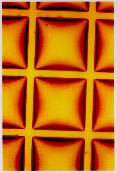
4 Microlens arrays Example shows lenses formed in photoresist on glass substrate. Lens spacing = 125 micrometres (µm) Microlenses generally defined as lenses having diameters less than 1mm. Simple lenses smaller size means, in principle, fewer aberrations. 4

5 Applications A common application is in digital cameras where microlenses are used to increase the fill-factor of the detector array 5


6 Applications Other applications include: Novel imaging systems for photocopiers 6

7 Shack-Hartmann wavefront sensor incident wavefront f Lens array CCD The incident wavefront is focused by the microlens array to the CCD. 7

8 Shack-Hartmann wavefront sensor f tilted wavefront Lenslet Array CCD wavefront slope at each lens can be deduced from the displacement of the spot wavefront is reconstructed by integrating the wavefront slope values 8
9 History of microlenses Robert Hooke made small lenses by melting glass filaments to form small spheres. Held close to eye he used them as simple microscopes and sketched what he saw. Hooke R. Preface to Micrographia. The Royal Society. London


10 Stanhope lenses Stanhope lens invented by Charles, Earl of Stanhope. Popular in 1800s with small images such as advertising on the back face. Held close to eye to reveal images. 10


11 Integral photography 1908, Gabriel Lippmann assembled an array of Stanhope lenses (Lippmann G. Epreuves reversibles. Photographies integrales. Comptes Rendus, 1908, 146, ) Used to record and reconstruct an integral image integral photography. Reversal of ray bundles generates pseudoscopic 3D image 11


12 Integral images Two views from one recording, showing parallax. Recorded on colour reversal film using array of microlenses 250 micrometre diameter. 12
13 Microlens fabrication Microoptics and microlens lens technology has developed rapidly over the last two decades with the growth in the microelectronics and optical fibre telecommunication industries. Advances in microfabrication techniques for integrated circuits - multilevel diffraction lenses. In 1988 Zoran Popovic at the Xerox Research Centre made microlenses by melting photoresist. Popovic, ZD, Sprague RA, Neville Connell GA. Appl.Opt. 27(7) (1988) Technique also explored by NPL. Went on to research needs and develop metrology for microlens arrays. NPL held with the IOP a series of conferences on microlens arrays in 1991, 1993, 1995, 1997, Japanese conferences on microooptics 1987 onwards. Need for international standards became apparent. 13
")

14 Microlenses by melting photoresist Typical dimensions: layer thickness = 15μm lens diameter = 100μm 22μm 400μm focal length = 100μm(f/1) 800μm(f/2) Daly D, Stevens R F, Hutley M C and Davies N, "The manufacture of microlenses by melting photoresist". Meas.Sci. Techn. 1, ,

15 Microlens arrays 15


16 Optical measurements at NPL Reference flat calibrated with respect to liquid surface, used to calibrate commercial interferometer used to measure customer s mirrors and lenses. However our instrument cannot measure very small components. Solution was to build micro-optic interferometer in which the test surface is imaged using a high quality microscope objective. 16


17 Mach-Zehnder interferometer for measurement of wavefronts transmitted by microlenses 17
18 Need for international standards Participants included: University of Erlangen, Nürnberg, Germany Optoelectronic Industry and Technology Development Association (OITDA) Japan University of North Carolina at Charlotte, USA Vrije Universitiet Brussel, Belgium Various international companies such as: Nippon Sheet Glass, GRINTEC Germany, Kodak USA, Wavefront Sciences. 18
19 Typical parameters: Microlens parameters Lens diameter Focal length Distance between lenses (pitch) Uniformity of array Wavefront quality Lens thickness (sag) Substrate thickness diameter < 1mm focal point wavefront substrate focal length f Simple design may mean less correction and large spherical aberration 19
20 Microlens parameters (ISO ) L 1 f E,f P x 2a P y L 2 f E,b h T 2a 20
21 BS EN ISO :2005 Microlens arrays part 1 vocabulary Defines optical properties and geometrical parameters Focal length in particular Difficult to locate principal plane and optical image plane 21
22 BS EN ISO :2006 Microlens arrays - part 2 Test methods for wavefront aberrations Optical surface shape useful for lens manufacturer and supplier Surface profile measured using stylus in contact Non-contacting methods include interferometry BS EN ISO :2005 Microlens arrays part 3 Test methods for optical properties other than wavefront aberrations This includes focal length, chromatic aberration, uniformity of spot positions BS EN ISO :2006 Microlens arrays part 4 Test methods for geometrical properties Properties such as pitch, modulation depth, thickness, radius of curvature, uniformity of array. Moire magnifier 22
23 [SC9 Meeting] Kobe (JP) Glasgow (UK) Boulder (US) Boulder (US) Maurah (GR) Milan (IT) Rusutsu (JP) Tokyo (JP) Nice (FR) Pforzheim (GR) Vienna (AT) London(UK) [Part.1] [Part.2] WD CD DIS FDIS WD CD DIS FDIS :Publish [Part.3 & 4] [Part.5] WD = Working Draft CD = Committee Draft DIS = Draft International Standard FDIS = Final Draft International Standard WD CD DIS FDIS WD/CD/DIS/FDIS Microlens arrays (ISO14880 series) standards development road map Miyashita T. "Standardization for Microlens and Microlens Arrays", Japanese Journal of Applied Physics(JJAP), Vol. 46, No. 8B (2007) pp
24 Conclusions Microlenses were made as long ago as The technology has developed rapidly over the last years. International manufacturing and use has led to the need for standard nomenclature and measurement methods. The ISO series of standards contributes to ensuring consistent specification and guidance to good measurement practice. 24
25 Acknowledgements: Department for Innovation, Universities & Skills (DIUS) Takaaki MIYASHITA, project leader for ISO microlens standards, Ricoh Company Ltd, Japan. References: 1) Miyashita T. Standardisation for microlenses and microlens arrays. Jap. Jnl. of Appl. Phys. vol 46, no8b, 2007, pp ) BS EN ISO series Microlens arrays parts , For further information, contact: richard.stevens@npl.co.uk 25
Adaptive Optics for LIGO
 Adaptive Optics for LIGO Justin Mansell Ginzton Laboratory LIGO-G990022-39-M Motivation Wavefront Sensor Outline Characterization Enhancements Modeling Projections Adaptive Optics Results Effects of Thermal
SpotOptics. The software people for optics OPAL O P A L
 Spotptics The software people for optics UTMTED WVEFRNT SENSR ccurate metrology of standard and aspherical lenses (single pass) ccurate metrology of spherical and flat mirrors (double pass) =0.3 to =50
WaveMaster IOL. Fast and accurate intraocular lens tester
 WaveMaster IOL Fast and accurate intraocular lens tester INTRAOCULAR LENS TESTER WaveMaster IOL Fast and accurate intraocular lens tester WaveMaster IOL is a new instrument providing real time analysis
OPAL. SpotOptics. AUTOMATED WAVEFRONT SENSOR Single and double pass O P A L
 Spotptics The software people for optics UTMTED WVEFRNT SENSR Single and double pass ccurate metrology of standard and aspherical lenses ccurate metrology of spherical and flat mirrors =0.3 to =60 mm F/1
WaveMaster IOL. Fast and Accurate Intraocular Lens Tester
 WaveMaster IOL Fast and Accurate Intraocular Lens Tester INTRAOCULAR LENS TESTER WaveMaster IOL Fast and accurate intraocular lens tester WaveMaster IOL is an instrument providing real time analysis of
An Optical Wavefront Sensor Based on a Double Layer Microlens Array
 Sensors 2011, 11, 10293-10307; doi:10.3390/s111110293 OPEN ACCESS sensors ISSN 1424-8220 www.mdpi.com/journal/sensors Article An Optical Wavefront Sensor Based on a Double Layer Microlens Array Vinna Lin,
Wavefront sensing by an aperiodic diffractive microlens array
 Wavefront sensing by an aperiodic diffractive microlens array Lars Seifert a, Thomas Ruppel, Tobias Haist, and Wolfgang Osten a Institut für Technische Optik, Universität Stuttgart, Pfaffenwaldring 9,
DIMENSIONAL MEASUREMENT OF MICRO LENS ARRAY WITH 3D PROFILOMETRY
 DIMENSIONAL MEASUREMENT OF MICRO LENS ARRAY WITH 3D PROFILOMETRY Prepared by Benjamin Mell 6 Morgan, Ste156, Irvine CA 92618 P: 949.461.9292 F: 949.461.9232 nanovea.com Today's standard for tomorrow's
Image Formation. Light from distant things. Geometrical optics. Pinhole camera. Chapter 36
 Light from distant things Chapter 36 We learn about a distant thing from the light it generates or redirects. The lenses in our eyes create images of objects our brains can process. This chapter concerns
Figure 7 Dynamic range expansion of Shack- Hartmann sensor using a spatial-light modulator
 Figure 4 Advantage of having smaller focal spot on CCD with super-fine pixels: Larger focal point compromises the sensitivity, spatial resolution, and accuracy. Figure 1 Typical microlens array for Shack-Hartmann
CHARA AO Calibration Process
 CHARA AO Calibration Process Judit Sturmann CHARA AO Project Overview Phase I. Under way WFS on telescopes used as tip-tilt detector Phase II. Not yet funded WFS and large DM in place of M4 on telescopes
Wavefront Sensing In Other Disciplines. 15 February 2003 Jerry Nelson, UCSC Wavefront Congress
 Wavefront Sensing In Other Disciplines 15 February 2003 Jerry Nelson, UCSC Wavefront Congress QuickTime and a Photo - JPEG decompressor are needed to see this picture. 15feb03 Nelson wavefront sensing
APPLICATION NOTE
 THE PHYSICS BEHIND TAG OPTICS TECHNOLOGY AND THE MECHANISM OF ACTION OF APPLICATION NOTE 12-001 USING SOUND TO SHAPE LIGHT Page 1 of 6 Tutorial on How the TAG Lens Works This brief tutorial explains the
Testing Aspheric Lenses: New Approaches
 Nasrin Ghanbari OPTI 521 - Synopsis of a published Paper November 5, 2012 Testing Aspheric Lenses: New Approaches by W. Osten, B. D orband, E. Garbusi, Ch. Pruss, and L. Seifert Published in 2010 Introduction
Use of Computer Generated Holograms for Testing Aspheric Optics
 Use of Computer Generated Holograms for Testing Aspheric Optics James H. Burge and James C. Wyant Optical Sciences Center, University of Arizona, Tucson, AZ 85721 http://www.optics.arizona.edu/jcwyant,
Radial Coupling Method for Orthogonal Concentration within Planar Micro-Optic Solar Collectors
 Radial Coupling Method for Orthogonal Concentration within Planar Micro-Optic Solar Collectors Jason H. Karp, Eric J. Tremblay and Joseph E. Ford Photonics Systems Integration Lab University of California
DETERMINING CALIBRATION PARAMETERS FOR A HARTMANN- SHACK WAVEFRONT SENSOR
 DETERMINING CALIBRATION PARAMETERS FOR A HARTMANN- SHACK WAVEFRONT SENSOR Felipe Tayer Amaral¹, Luciana P. Salles 2 and Davies William de Lima Monteiro 3,2 Graduate Program in Electrical Engineering -
Explanation of Aberration and Wavefront
 Explanation of Aberration and Wavefront 1. What Causes Blur? 2. What is? 4. What is wavefront? 5. Hartmann-Shack Aberrometer 6. Adoption of wavefront technology David Oh 1. What Causes Blur? 2. What is?
Converging Lenses. Parallel rays are brought to a focus by a converging lens (one that is thicker in the center than it is at the edge).
.") Chapter 30: Lenses Types of Lenses Piece of glass or transparent material that bends parallel rays of light so they cross and form an image Two types: Converging Diverging Converging Lenses Parallel rays
Chapter 30: Lenses Types of Lenses Piece of glass or transparent material that bends parallel rays of light so they cross and form an image Two types: Converging Diverging Converging Lenses Parallel rays
EE119 Introduction to Optical Engineering Spring 2003 Final Exam. Name:
 EE119 Introduction to Optical Engineering Spring 2003 Final Exam Name: SID: CLOSED BOOK. THREE 8 1/2 X 11 SHEETS OF NOTES, AND SCIENTIFIC POCKET CALCULATOR PERMITTED. TIME ALLOTTED: 180 MINUTES Fundamental
Algebra Based Physics. Reflection. Slide 1 / 66 Slide 2 / 66. Slide 3 / 66. Slide 4 / 66. Slide 5 / 66. Slide 6 / 66.
 Slide 1 / 66 Slide 2 / 66 Algebra Based Physics Geometric Optics 2015-12-01 www.njctl.org Slide 3 / 66 Slide 4 / 66 Table of ontents lick on the topic to go to that section Reflection Refraction and Snell's
Vision Research at. Validation of a Novel Hartmann-Moiré Wavefront Sensor with Large Dynamic Range. Wavefront Science Congress, Feb.
 Wavefront Science Congress, Feb. 2008 Validation of a Novel Hartmann-Moiré Wavefront Sensor with Large Dynamic Range Xin Wei 1, Tony Van Heugten 2, Nikole L. Himebaugh 1, Pete S. Kollbaum 1, Mei Zhang
Two step process for the fabrication of diffraction limited concave microlens arrays
 Two step process for the fabrication of diffraction limited concave microlens arrays Patrick Ruffieux 1*, Toralf Scharf 1, Irène Philipoussis 1, Hans Peter Herzig 1, Reinhard Voelkel 2, and Kenneth J.
Chapter Ray and Wave Optics
 109 Chapter Ray and Wave Optics 1. An astronomical telescope has a large aperture to [2002] reduce spherical aberration have high resolution increase span of observation have low dispersion. 2. If two
J. C. Wyant Fall, 2012 Optics Optical Testing and Testing Instrumentation
 J. C. Wyant Fall, 2012 Optics 513 - Optical Testing and Testing Instrumentation Introduction 1. Measurement of Paraxial Properties of Optical Systems 1.1 Thin Lenses 1.1.1 Measurements Based on Image Equation
Physics 431 Final Exam Examples (3:00-5:00 pm 12/16/2009) TIME ALLOTTED: 120 MINUTES Name: Signature:
 TIME ALLOTTED: 120 MINUTES Name: Signature:") Physics 431 Final Exam Examples (3:00-5:00 pm 12/16/2009) TIME ALLOTTED: 120 MINUTES Name: PID: Signature: CLOSED BOOK. TWO 8 1/2 X 11 SHEET OF NOTES (double sided is allowed), AND SCIENTIFIC POCKET CALCULATOR
Physics 431 Final Exam Examples (3:00-5:00 pm 12/16/2009) TIME ALLOTTED: 120 MINUTES Name: PID: Signature: CLOSED BOOK. TWO 8 1/2 X 11 SHEET OF NOTES (double sided is allowed), AND SCIENTIFIC POCKET CALCULATOR
Handbook of Optical Systems
 Handbook of Optical Systems Volume 5: Metrology of Optical Components and Systems von Herbert Gross, Bernd Dörband, Henriette Müller 1. Auflage Handbook of Optical Systems Gross / Dörband / Müller schnell
SELF-CALIBRATION TECHNIQUE FOR TRANSMITTED WAVEFRO`NT MEASURMENTS OF MICRO-OPTICS. Brent C. Bergner
 SELF-CALIBRATION TECHNIQUE FOR TRANSMITTED WAVEFRO`NT MEASURMENTS OF MICRO-OPTICS by Brent C. Bergner A thesis submitted to the faculty of the University of North Carolina at Charlotte in partial fulfillment
Ron Liu OPTI521-Introductory Optomechanical Engineering December 7, 2009
 Synopsis of METHOD AND APPARATUS FOR IMPROVING VISION AND THE RESOLUTION OF RETINAL IMAGES by David R. Williams and Junzhong Liang from the US Patent Number: 5,777,719 issued in July 7, 1998 Ron Liu OPTI521-Introductory
Ocular Shack-Hartmann sensor resolution. Dan Neal Dan Topa James Copland
 Ocular Shack-Hartmann sensor resolution Dan Neal Dan Topa James Copland Outline Introduction Shack-Hartmann wavefront sensors Performance parameters Reconstructors Resolution effects Spot degradation Accuracy
Lecture 2: Geometrical Optics. Geometrical Approximation. Lenses. Mirrors. Optical Systems. Images and Pupils. Aberrations.
 Lecture 2: Geometrical Optics Outline 1 Geometrical Approximation 2 Lenses 3 Mirrors 4 Optical Systems 5 Images and Pupils 6 Aberrations Christoph U. Keller, Leiden Observatory, keller@strw.leidenuniv.nl
Aberrations and adaptive optics for biomedical microscopes
 Aberrations and adaptive optics for biomedical microscopes Martin Booth Department of Engineering Science And Centre for Neural Circuits and Behaviour University of Oxford Outline Rays, wave fronts and
Optical Characterization and Defect Inspection for 3D Stacked IC Technology
 Minapad 2014, May 21 22th, Grenoble; France Optical Characterization and Defect Inspection for 3D Stacked IC Technology J.Ph.Piel, G.Fresquet, S.Perrot, Y.Randle, D.Lebellego, S.Petitgrand, G.Ribette FOGALE
Refractive Micro-optics for Multi-spot and Multi-line Generation
 Refractive Micro-optics for Multi-spot and Multi-line Generation Maik ZIMMERMANN *1, Michael SCHMIDT *1 and Andreas BICH *2, Reinhard VOELKEL *2 *1 Bayerisches Laserzentrum GmbH, Konrad-Zuse-Str. 2-6,
Practice Problems (Geometrical Optics)
") 1 Practice Problems (Geometrical Optics) 1. A convex glass lens (refractive index = 3/2) has a focal length of 8 cm when placed in air. What is the focal length of the lens when it is immersed in water
1 Practice Problems (Geometrical Optics) 1. A convex glass lens (refractive index = 3/2) has a focal length of 8 cm when placed in air. What is the focal length of the lens when it is immersed in water
Industrial quality control HASO for ensuring the quality of NIR optical components
 Industrial quality control HASO for ensuring the quality of NIR optical components In the sector of industrial detection, the ability to massproduce reliable, high-quality optical components is synonymous
Optical Components for Laser Applications. Günter Toesko - Laserseminar BLZ im Dezember
 Günter Toesko - Laserseminar BLZ im Dezember 2009 1 Aberrations An optical aberration is a distortion in the image formed by an optical system compared to the original. It can arise for a number of reasons
Study on Imaging Quality of Water Ball Lens
 2017 2nd International Conference on Mechatronics and Information Technology (ICMIT 2017) Study on Imaging Quality of Water Ball Lens Haiyan Yang1,a,*, Xiaopan Li 1,b, 1,c Hao Kong, 1,d Guangyang Xu and1,eyan
Algebra Based Physics. Reflection. Slide 1 / 66 Slide 2 / 66. Slide 3 / 66. Slide 4 / 66. Slide 5 / 66. Slide 6 / 66.
 Slide 1 / 66 Slide 2 / 66 lgebra ased Physics Geometric Optics 2015-12-01 www.njctl.org Slide 3 / 66 Slide 4 / 66 Table of ontents lick on the topic to go to that section Reflection Refraction and Snell's
Shack Hartmann Sensor Based on a Low-Aperture Off-Axis Diffraction Lens Array
 ISSN 8756-699, Optoelectronics, Instrumentation and Data Processing, 29, Vol. 45, No. 2, pp. 6 7. c Allerton Press, Inc., 29. Original Russian Text c V.P. Lukin, N.N. Botygina, O.N. Emaleev, V.P. Korol
Ch 24. Geometric Optics
 text concept Ch 24. Geometric Optics Fig. 24 3 A point source of light P and its image P, in a plane mirror. Angle of incidence =angle of reflection. text. Fig. 24 4 The blue dashed line through object
Chapter 18 Optical Elements
 Chapter 18 Optical Elements GOALS When you have mastered the content of this chapter, you will be able to achieve the following goals: Definitions Define each of the following terms and use it in an operational
Lecture 2: Geometrical Optics. Geometrical Approximation. Lenses. Mirrors. Optical Systems. Images and Pupils. Aberrations.
 Lecture 2: Geometrical Optics Outline 1 Geometrical Approximation 2 Lenses 3 Mirrors 4 Optical Systems 5 Images and Pupils 6 Aberrations Christoph U. Keller, Leiden Observatory, keller@strw.leidenuniv.nl
Collimation Tester Instructions
 Description Use shear-plate collimation testers to examine and adjust the collimation of laser light, or to measure the wavefront curvature and divergence/convergence magnitude of large-radius optical
Lens Design I. Lecture 3: Properties of optical systems II Herbert Gross. Summer term
 Lens Design I Lecture 3: Properties of optical systems II 205-04-8 Herbert Gross Summer term 206 www.iap.uni-jena.de 2 Preliminary Schedule 04.04. Basics 2.04. Properties of optical systrems I 3 8.04.
Fabrication of micro structures on curve surface by X-ray lithography
 Fabrication of micro structures on curve surface by X-ray lithography Yigui Li 1, Susumu Sugiyama 2 Abstract We demonstrate experimentally the x-ray lithography techniques to fabricate micro structures
Lecture 22 Optical MEMS (4)
") EEL6935 Advanced MEMS (Spring 2005) Instructor: Dr. Huikai Xie Lecture 22 Optical MEMS (4) Agenda: Refractive Optical Elements Microlenses GRIN Lenses Microprisms Reference: S. Sinzinger and J. Jahns,
EEL6935 Advanced MEMS (Spring 2005) Instructor: Dr. Huikai Xie Lecture 22 Optical MEMS (4) Agenda: Refractive Optical Elements Microlenses GRIN Lenses Microprisms Reference: S. Sinzinger and J. Jahns,
Development of a new multi-wavelength confocal surface profilometer for in-situ automatic optical inspection (AOI)
") Development of a new multi-wavelength confocal surface profilometer for in-situ automatic optical inspection (AOI) Liang-Chia Chen 1#, Chao-Nan Chen 1 and Yi-Wei Chang 1 1. Institute of Automation Technology,
Development of a new multi-wavelength confocal surface profilometer for in-situ automatic optical inspection (AOI) Liang-Chia Chen 1#, Chao-Nan Chen 1 and Yi-Wei Chang 1 1. Institute of Automation Technology,
Lenses Design Basics. Introduction. RONAR-SMITH Laser Optics. Optics for Medical. System. Laser. Semiconductor Spectroscopy.
 Introduction Optics Application Lenses Design Basics a) Convex lenses Convex lenses are optical imaging components with positive focus length. After going through the convex lens, parallel beam of light
Paper Synopsis. Xiaoyin Zhu Nov 5, 2012 OPTI 521
 Paper Synopsis Xiaoyin Zhu Nov 5, 2012 OPTI 521 Paper: Active Optics and Wavefront Sensing at the Upgraded 6.5-meter MMT by T. E. Pickering, S. C. West, and D. G. Fabricant Abstract: This synopsis summarized
Lenses. A transparent object used to change the path of light Examples: Human eye Eye glasses Camera Microscope Telescope
 SNC2D Lenses A transparent object used to change the path of light Examples: Human eye Eye glasses Camera Microscope Telescope Reading stones used by monks, nuns, and scholars ~1000 C.E. Lenses THERE ARE
Multi-aperture camera module with 720presolution
 Multi-aperture camera module with 720presolution using microoptics A. Brückner, A. Oberdörster, J. Dunkel, A. Reimann, F. Wippermann, A. Bräuer Fraunhofer Institute for Applied Optics and Precision Engineering
Parallel Mode Confocal System for Wafer Bump Inspection
 Parallel Mode Confocal System for Wafer Bump Inspection ECEN5616 Class Project 1 Gao Wenliang wen-liang_gao@agilent.com 1. Introduction In this paper, A parallel-mode High-speed Line-scanning confocal
PHYSICS OPTICS. Mr Rishi Gopie
 OPTICS Mr Rishi Gopie Ray Optics II Images formed by lens maybe real or virtual and may have different characteristics and locations that depend on: i) The type of lens involved, whether converging or
Practical Flatness Tech Note
 Practical Flatness Tech Note Understanding Laser Dichroic Performance BrightLine laser dichroic beamsplitters set a new standard for super-resolution microscopy with λ/10 flatness per inch, P-V. We ll
Analysis of Hartmann testing techniques for large-sized optics
 Analysis of Hartmann testing techniques for large-sized optics Nadezhda D. Tolstoba St.-Petersburg State Institute of Fine Mechanics and Optics (Technical University) Sablinskaya ul.,14, St.-Petersburg,
Solution of Exercises Lecture Optical design with Zemax Part 6
 2013-06-17 Prof. Herbert Gross Friedrich Schiller University Jena Institute of Applied Physics Albert-Einstein-Str 15 07745 Jena Solution of Exercises Lecture Optical design with Zemax Part 6 6 Illumination
Contouring aspheric surfaces using two-wavelength phase-shifting interferometry
 OPTICA ACTA, 1985, VOL. 32, NO. 12, 1455-1464 Contouring aspheric surfaces using two-wavelength phase-shifting interferometry KATHERINE CREATH, YEOU-YEN CHENG and JAMES C. WYANT University of Arizona,
The Brownie Camera. Lens Design OPTI 517. Prof. Jose Sasian
 The Brownie Camera Lens Design OPTI 517 http://www.history.roch ester.edu/class/kodak/k odak.htm George Eastman (1854-1932), was an ingenious man who contributed greatly to the field of photography. He
Option G 2: Lenses. The diagram below shows the image of a square grid as produced by a lens that does not cause spherical aberration.
 Name: Date: Option G 2: Lenses 1. This question is about spherical aberration. The diagram below shows the image of a square grid as produced by a lens that does not cause spherical aberration. In the
3.0 Alignment Equipment and Diagnostic Tools:
 3.0 Alignment Equipment and Diagnostic Tools: Alignment equipment The alignment telescope and its use The laser autostigmatic cube (LACI) interferometer A pin -- and how to find the center of curvature
IMAGE SENSOR SOLUTIONS. KAC-96-1/5" Lens Kit. KODAK KAC-96-1/5" Lens Kit. for use with the KODAK CMOS Image Sensors. November 2004 Revision 2
 KODAK for use with the KODAK CMOS Image Sensors November 2004 Revision 2 1.1 Introduction Choosing the right lens is a critical aspect of designing an imaging system. Typically the trade off between image
Fabrication of plastic microlens array using gas-assisted micro-hot-embossing with a silicon mold
 Infrared Physics & Technology 48 (2006) 163 173 www.elsevier.com/locate/infrared Fabrication of plastic microlens array using gas-assisted micro-hot-embossing with a silicon mold C.-Y. Chang a, S.-Y. Yang
U.S. Air Force Phillips hboratoq, Kirtland AFB, NM 87117, 505/ , FAX:
 Evaluation of Wavefront Sensors Based on Etched R. E. Pierson, K. P. Bishop, E. Y. Chen Applied Technology Associates, 19 Randolph SE, Albuquerque, NM 8716, SOS/846-61IO, FAX: 59768-1391 D. R. Neal Sandia
Optical Engineering 421/521 Sample Questions for Midterm 1
 Optical Engineering 421/521 Sample Questions for Midterm 1 Short answer 1.) Sketch a pechan prism. Name a possible application of this prism., write the mirror matrix for this prism (or any other common
Lecture 17. Image formation Ray tracing Calculation. Lenses Convex Concave. Mirrors Convex Concave. Optical instruments
 Lecture 17. Image formation Ray tracing Calculation Lenses Convex Concave Mirrors Convex Concave Optical instruments Image formation Laws of refraction and reflection can be used to explain how lenses
Lens Design I. Lecture 3: Properties of optical systems II Herbert Gross. Summer term
 Lens Design I Lecture 3: Properties of optical systems II 207-04-20 Herbert Gross Summer term 207 www.iap.uni-jena.de 2 Preliminary Schedule - Lens Design I 207 06.04. Basics 2 3.04. Properties of optical
Confocal principle for macro- and microscopic surface and defect analysis
 Confocal principle for macro- and microscopic surface and defect analysis Hans J. Tiziani, FELLOW SPIE Michael Wegner Daniela Steudle Institut für Technische Optik Pfaffenwaldring 9 70569 Stuttgart, Germany
OPTOCRAFT Unleashed wavefront technology
 OPTOCRAFT Unleashed wavefront technology Individual demands qualified realization Manufacturers of plastic optics, aspheres, micro- or wafer-based optics will increasingly have to replace traditional measurement
Difrotec Product & Services. Ultra high accuracy interferometry & custom optical solutions
 Difrotec Product & Services Ultra high accuracy interferometry & custom optical solutions Content 1. Overview 2. Interferometer D7 3. Benefits 4. Measurements 5. Specifications 6. Applications 7. Cases
Integrated Focusing Photoresist Microlenses on AlGaAs Top-Emitting VCSELs
 Integrated Focusing Photoresist Microlenses on AlGaAs Top-Emitting VCSELs Andrea Kroner We present 85 nm wavelength top-emitting vertical-cavity surface-emitting lasers (VCSELs) with integrated photoresist
 Telecentric Imaging Object space telecentricity stop source: edmund optics The 5 classical Seidel Aberrations First order aberrations Spherical Aberration (~r 4 ) Origin: different focal lengths for different
Lecture 4: Geometrical Optics 2. Optical Systems. Images and Pupils. Rays. Wavefronts. Aberrations. Outline
 Lecture 4: Geometrical Optics 2 Outline 1 Optical Systems 2 Images and Pupils 3 Rays 4 Wavefronts 5 Aberrations Christoph U. Keller, Leiden University, keller@strw.leidenuniv.nl Lecture 4: Geometrical
Super High Vertical Resolution Non-Contact 3D Surface Profiler BW-S500/BW-D500 Series
 Super High Vertical Resolution Non-Contact 3D Surface Profiler BW-S500/BW-D500 Series Nikon's proprietary scanning-type optical interference measurement technology achieves 1pm* height resolution. * Height
EE119 Introduction to Optical Engineering Spring 2002 Final Exam. Name:
 EE119 Introduction to Optical Engineering Spring 2002 Final Exam Name: SID: CLOSED BOOK. FOUR 8 1/2 X 11 SHEETS OF NOTES, AND SCIENTIFIC POCKET CALCULATOR PERMITTED. TIME ALLOTTED: 180 MINUTES Fundamental
Lens Design I. Lecture 5: Advanced handling I Herbert Gross. Summer term
 Lens Design I Lecture 5: Advanced handling I 2018-05-17 Herbert Gross Summer term 2018 www.iap.uni-jena.de 2 Preliminary Schedule - Lens Design I 2018 1 12.04. Basics 2 19.04. Properties of optical systems
Phys 531 Lecture 9 30 September 2004 Ray Optics II. + 1 s i. = 1 f
 Phys 531 Lecture 9 30 September 2004 Ray Optics II Last time, developed idea of ray optics approximation to wave theory Introduced paraxial approximation: rays with θ 1 Will continue to use Started disussing
Computer Generated Holograms for Optical Testing
 Computer Generated Holograms for Optical Testing Dr. Jim Burge Associate Professor Optical Sciences and Astronomy University of Arizona jburge@optics.arizona.edu 520-621-8182 Computer Generated Holograms
1.6 Beam Wander vs. Image Jitter
 8 Chapter 1 1.6 Beam Wander vs. Image Jitter It is common at this point to look at beam wander and image jitter and ask what differentiates them. Consider a cooperative optical communication system that
An Off-Axis Hartmann Sensor for Measurement of Wavefront Distortion in Interferometric Detectors
 An Off-Axis Hartmann Sensor for Measurement of Wavefront Distortion in Interferometric Detectors Aidan Brooks, Peter Veitch, Jesper Munch Department of Physics, University of Adelaide Outline of Talk Discuss
Micro-Optic Solar Concentration and Next-Generation Prototypes
 Micro-Optic Solar Concentration and Next-Generation Prototypes Jason H. Karp, Eric J. Tremblay and Joseph E. Ford Photonics Systems Integration Lab University of California San Diego Jacobs School of Engineering
Laboratory 7: Properties of Lenses and Mirrors
 Laboratory 7: Properties of Lenses and Mirrors Converging and Diverging Lens Focal Lengths: A converging lens is thicker at the center than at the periphery and light from an object at infinity passes
Lecture 3: Geometrical Optics 1. Spherical Waves. From Waves to Rays. Lenses. Chromatic Aberrations. Mirrors. Outline
 Lecture 3: Geometrical Optics 1 Outline 1 Spherical Waves 2 From Waves to Rays 3 Lenses 4 Chromatic Aberrations 5 Mirrors Christoph U. Keller, Leiden Observatory, keller@strw.leidenuniv.nl Lecture 3: Geometrical
Optics Practice. Version #: 0. Name: Date: 07/01/2010
 Optics Practice Date: 07/01/2010 Version #: 0 Name: 1. Which of the following diagrams show a real image? a) b) c) d) e) i, ii, iii, and iv i and ii i and iv ii and iv ii, iii and iv 2. A real image is
SNC2D PHYSICS 5/25/2013. LIGHT & GEOMETRIC OPTICS L Converging & Diverging Lenses (P ) Curved Lenses. Curved Lenses
 Curved Lenses. Curved Lenses") SNC2D PHYSICS LIGHT & GEOMETRIC OPTICS L Converging & Diverging Lenses (P.448-450) Curved Lenses We see the world through lenses even if we do not wear glasses or contacts. We all have natural lenses in
SNC2D PHYSICS LIGHT & GEOMETRIC OPTICS L Converging & Diverging Lenses (P.448-450) Curved Lenses We see the world through lenses even if we do not wear glasses or contacts. We all have natural lenses in
Notation for Mirrors and Lenses. Chapter 23. Types of Images for Mirrors and Lenses. More About Images
 Notation for Mirrors and Lenses Chapter 23 Mirrors and Lenses Sections: 4, 6 Problems:, 8, 2, 25, 27, 32 The object distance is the distance from the object to the mirror or lens Denoted by p The image
Light guide with internal mirror array for LCD backlight
 IoP Optical Group & DMAC, Micro-optics and Metrology meeting 26 November 2003, Cambridge Light guide with internal mirror array for LCD backlight David R. Selviah and Kai Wang Department of Electronic
Aspheric Lenses. Contact us for a Stock or Custom Quote Today! Edmund Optics BROCHURE
 Edmund Optics BROCHURE Aspheric Lenses products & capabilities Contact us for a Stock or Custom Quote Today! USA: +1-856-547-3488 EUROPE: +44 (0) 1904 788600 ASIA: +65 6273 6644 JAPAN: +81-3-3944-6210
OPTINO. SpotOptics VERSATILE WAVEFRONT SENSOR O P T I N O
 Spotptics he software people for optics VERSALE WAVEFR SESR Accurate metrology in single and double pass Lenses, mirrors and laser beams Any focal length and diameter Large dynamic range Adaptable for
OPTICAL SYSTEMS OBJECTIVES
 101 L7 OPTICAL SYSTEMS OBJECTIVES Aims Your aim here should be to acquire a working knowledge of the basic components of optical systems and understand their purpose, function and limitations in terms
Asphere testing with a Fizeau interferometer based on a combined computer-generated hologram
 172 J. Opt. Soc. Am. A/ Vol. 23, No. 1/ January 2006 J.-M. Asfour and A. G. Poleshchuk Asphere testing with a Fizeau interferometer based on a combined computer-generated hologram Jean-Michel Asfour Dioptic
A BASIC EXPERIMENTAL STUDY OF CAST FILM EXTRUSION PROCESS FOR FABRICATION OF PLASTIC MICROLENS ARRAY DEVICE
 A BASIC EXPERIMENTAL STUDY OF CAST FILM EXTRUSION PROCESS FOR FABRICATION OF PLASTIC MICROLENS ARRAY DEVICE Chih-Yuan Chang and Yi-Min Hsieh and Xuan-Hao Hsu Department of Mold and Die Engineering, National
THE OPTICAL SYSTEMS OF LHCb RICHes: A STUDY ON THE MIRROR WALLS AND MIRROR SPECIFICATIONS
 LHCb 2000-071 THE OPTICAL SYSTEMS OF LHCb RICHes: A STUDY ON THE MIRROR WALLS AND MIRROR SPECIFICATIONS C. D Ambrosio, L. Fernandez, M. Laub, D. Piedigrossi CERN, 1211 Geneva, Switzerland INTRODUCTION
Optical System Design
 Phys 531 Lecture 12 14 October 2004 Optical System Design Last time: Surveyed examples of optical systems Today, discuss system design Lens design = course of its own (not taught by me!) Try to give some
Condition Mirror Refractive Lens Concave Focal Length Positive Focal Length Negative. Image distance positive
 Comparison between mirror lenses and refractive lenses Condition Mirror Refractive Lens Concave Focal Length Positive Focal Length Negative Convex Focal Length Negative Focal Length Positive Image location
Chapter 23. Mirrors and Lenses
 Chapter 23 Mirrors and Lenses Mirrors and Lenses The development of mirrors and lenses aided the progress of science. It led to the microscopes and telescopes. Allowed the study of objects from microbes
Integrated micro-optical imaging system with a high interconnection capacity fabricated in planar optics
 Integrated micro-optical imaging system with a high interconnection capacity fabricated in planar optics Stefan Sinzinger and Jürgen Jahns An integrated free-space optical interconnection system with 2500
Design and optimization of microlens array based high resolution beam steering system
 Design and optimization of microlens array based high resolution beam steering system Ata Akatay and Hakan Urey Department of Electrical Engineering, Koc University, Sariyer, Istanbul 34450, Turkey hurey@ku.edu.tr
X-ray mirror metrology using SCOTS/deflectometry Run Huang a, Peng Su a*, James H. Burge a and Mourad Idir b
 X-ray mirror metrology using SCOTS/deflectometry Run Huang a, Peng Su a*, James H. Burge a and Mourad Idir b a College of Optical Sciences, the University of Arizona, Tucson, AZ 85721, U.S.A. b Brookhaven
UNIVERSITY OF NAIROBI COLLEGE OF EDUCATION AND EXTERNAL STUDIES
 UNIVERSITY OF NAIROBI COLLEGE OF EDUCATION AND EXTERNAL STUDIES COURSE TITLE: BED (SCIENCE) UNIT TITLE: WAVES AND OPTICS UNIT CODE: SPH 103 UNIT AUTHOR: PROF. R.O. GENGA DEPARTMENT OF PHYSICS UNIVERSITY