Catch Sensors User Guide
|
|
|
- Antonia Porter
- 6 years ago
- Views:
Transcription


1 Catch Sensors User Guide
2
3 Contents iii Contents Legal... 5 Disclaimer... 5 Copyright... 5 History...5 Introduction and Presentation... 6 Introduction... 6 Applications...7 Safety Guidelines...10 Description...11 Firmware Technical Specifications Main Parts Operational Mode Indicator...17 Installation Steps Sensor Configuration...19 Installing Mosa Connecting the Sensor to Mosa Calibrating the Catch Sensor Testing the Catch Sensor on Mosa...22 Catch Explorer Specific Settings...23 Configuring the Uplink and Down Settings Configuring Catch Sensor Telegrams...26 Catch...26 Temperature Depth Pitch and Roll Catch Hybrid PI Catch Hybrid Configuring the Uplink Power Testing Measures...30 Exporting Configuration Settings for Record Keeping Exporting Sensor Configuration for Receiver System Configuration and Display...33 Adding the Sensor to the Receiver Adding the Sensor with a Configuration File Adding the Sensor Manually Adding the Sensor to the Receiver...34 Configuring the Sensor Settings Configuring Data Display on Scala...39 Installation Installing the Sensor on the Trawl...44
4 Servicing and Maintenance Interference Check...47 Spectrum Analyzer Display Checking Noise Interference...47 Charging the Sensor Maintenance Cleaning the Sensor Maintenance Checklist Replacing the Pull Cords Replacing the Catch Magnet Troubleshooting Mosa does not start due to error message Data in Scala is wrong...56 Echogram is fixed and blue...56 Sensor has difficulty connecting to Mosa Catch Explorer images are incorrect when beginning towing Catch status remains full or empty Support Contact Appendix A: Frequency Plan...59 Index...61
5 Catch Sensors V1 Legal Legal Disclaimer Copyright History Marport endeavour to ensure that all information in this document is correct and fairly stated, but does not accept liability for any errors or omissions Marport. All Rights reserved. No part of this document may be reproduced, stored in a retrieval system or transmitted in any form by any means; electronic, mechanical, photocopying or otherwise, without the express written permission from Marport. Marport, the Marport logo and Software Defined Sonar are registered trademarks of Marport. All other brands, products and company names mentioned are the trademark and property of its respective owners only. Marport is a division of Airmar Technology Corporation. V1 10/02/17 First release V2 V3 5

6 Catch Sensors V1 Introduction and Presentation Introduction and Presentation Tip: Click Marport logo at the bottom of pages to come back to the table of contents. Introduction Marport's catch sensors tell you when your trawl starts to fill. Placed on the top of the trawl codend, they monitor the amount of catch that you have and warn you when the trawl is full. You can even use them to determine a precise amount of fish inside the trawl net. This way, you can monitor the contents of the codend as you are fishing, avoid problems of overfilling and increase fish survival rate inside the trawl net. It is recommended to install several sensors along the trawl to better follow the filling processes. There are two types of catch sensors: Catch sensor: gives you the catch status of the trawl (empty or full), along with depth, water temperature and pitch and roll information. Catch sensors can emit on a single frequency of 40 khz (Marport, Scanmar) or 70 khz (Simrad, Wesmar), or on a dual frequency (40 khz/70 khz). Catch Explorer: gives you the catch status of the trawl, with depth, water temperature and pitch and roll information. In addition, it provides an echogram image of the volume of catch inside the codend. 6
7 Catch Sensors V1 Introduction and Presentation Applications Here are some examples of data received from Catch Explorer and Catch sensors displayed in Scala. Catch Control System Installation You can install several sensors on the codend to better follow the filling processes. It is very useful to determine the amount of fish inside the trawl net: you can prevent damage to fish and increase the security of crew and vessel. For example, you can install three sensors on the codend. They will trigger one by one, according to the amount of fish inside the codend. After a few tows, you can estimate the amount of tonnage of fish that you have depending on whether one, two or three sensors display a full status. 7

8 Catch Sensors V1 Introduction and Presentation Catch Explorer display When the codend is full, you cannot see the sea bottom anymore because fish may block the signal. 8


9 Catch Sensors V1 Introduction and Presentation Catch sensors display Examples of 3 catch sensors with depth, pitch and roll. 9
10 Catch Sensors V1 Introduction and Presentation Safety Guidelines Important: To ensure proper and safe use of this equipment, carefully read and follow the instructions in this manual. Basic good practices When using the product, be careful: mechanical shocks can cause damage to the electronic components inside. Never place the product in a hazardous and/or flammable atmosphere. Product installation and use Install and use this product in accordance with this user manual. Incorrect use of the product may cause damage to the components or void the warranty. Only qualified Marport dealers can do internal sensor maintenance and repairs. Precautions Warning: In case of water ingress in the product, do not charge it: battery may vent or rupture, causing product or physical damage. 10
11 Catch Sensors V1 Introduction and Presentation Description Firmware About Catch Firmware Standard Catch firmware is compatible with Marport and Scanmar systems. Sensors emit at a frequency around 40kHz. Catch hybrid 70 firmware is compatible with Marport, Scanmar, Simrad and Wesmar systems. Sensors can emit at 2 frequencies: 40kHz (Marport, Scanmar) and 70kHz (Simrad, Wesmar). Catch hybrid PI firmware is compatible with Simrad PI, Marport and Scanmar systems. Sensors can communicate with Simrad PI and Marport or Scanmar systems at the same time. Product Name Firmware Name Firmware Number Catch Catch hybrid 70 Catch hybrid PI Catch Catch with depth Catch with depth, temp Catch with pitch & roll Catch with pitch & roll, depth Catch with pitch & roll, temp Catch with pitch & roll, depth, temp Catch with temp Catch hybrid70 Catch hybrid70 with depth Catch hybrid70 with depth, temp Catch hybrid70 with depth, temp, pitch & roll Catch hybrid70 with pitch & roll Catch hybrid70 with depth, pitch & roll Catch hybrid70 with pitch & roll, temp Catch hybrid70 with temp Catch hybrid sensor (Simrad PI + 70 khz) FIRM001 FIRM017 FIRM018 FIRM002 FIRM022 FIRM019 FIRM023 FIRM016 FIRM005 FIRM025 FIRM006 FIRM008 FIRM007 FIRM027 FIRM026 FIRM024 FIRM033 11
12 Catch Sensors V1 Introduction and Presentation Product Name Firmware Name Firmware Number Catch compatible with Simrad and Wesmar only Catch hybrid PI Catch hybrid PI with pitch, roll, depth Catch sensor with depth (Simrad PI) Catch compatible Simrad 70 + Wesmar Catch compatible Simrad PI FIRM028 FIRM029 FIRM034 FIRM003 FIRM009 Catch twister Catch roll twister FIRM037 Catch Explorer V2 TE/Catch FIRM127 Catch Explorer V3 TE/Catch V3 TE/Catch V3 with depth TE/Catch V3 with depth, pitch & roll TE/Catch V3 with depth, temp, pitch & roll TE/Catch V3 with pitch & roll FIRM130 FIRM131 FIRM133 FIRM134 FIRM132 12
13 Catch Sensors V1 Introduction and Presentation Technical Specifications Catch Sensor Uplink frequency 30 to 60 khz Range to vessel up to 2500 m* Depth range up to 1800 m Pitch angle ±90 Roll angle ±90 (±180 for catch twister) Pitch & roll accuracy ±0.1 Depth resolution Temp measurement range Temp accuracy 0.1 m with 0.1% accuracy -5 C to +25 C ±0.1 C Data update rate Catch full: 20 sec. - Catch empty: 30 sec. - Depth: 3-8 sec. - Temp: 3-16 sec. - Pitch & roll: 5-14 sec. Typical battery life Up to 740 hours Charging time Battery type Weight in air Weight in water Standard: 6-8 hours Fast Charge: 2.5 hours Lithium-Ion 5 kg 0.9 kg Warranty 2 years (Sensor & Battery) ** Catch Explorer Uplink frequency 30 to 60 khz Range to vessel up to 2500 m* Sounder range Sounder broadband frequency Pitch angle ±90 Roll angle ±180 Pitch & roll accuracy ±0.1 V2: 5-80 m V3: m Configurable between khz Depth resolution Temp measurement range Temp accuracy 0.1 m with 0.1% accuracy -5 C to +25 C ±0.1 C 13
14 Catch Sensors V1 Introduction and Presentation Data update rate V2: depth, catch: 2-3 sec. - temp, pitch, roll, battery: sec. - echogram: 1-2 sec. V3: depth, catch: 4 sec. - temp, pitch, roll, battery: 17 sec. - echogram: 1.5 sec. Typical battery life Up to 19 hours Standard: 6-8 hours Charging time Fast Charge: 2.5 hours Battery type Lithium-Ion Weight in air 5 kg Weight in water 0.9 kg Warranty 2 years (Sensor & Battery) ** *Reference only. Depends on functions enabled. / Depends on sensor uplink power and options. / Based on average charging time. / **Marport Standard Marine Limited Warranty Catch Explorer Beamwidths Beamwidths for Uplink pings khz -3dB Beamwidths for Down 360 khz -3dB 13 14

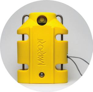
15 Catch Sensors V1 Introduction and Presentation Dimensions 15


16 Catch Sensors V1 Introduction and Presentation Main Parts External View End cap Side view On the transducer, down sounder is identified with a circle and a A. 16

17 Catch Sensors V1 Introduction and Presentation Operational Mode Indicator Indicators from the transducer State Situation Operation LED Charging Charger plug is connected. Batteries are charging. No light. Running Sensor is in water or activated with jumper. After an initialization phase, echo sounder is operating. Flashing red Configuring Sensor is out of water. Configuration via Bluetooth. Turns off after 10 minutes without user action. Flashing green 17


18 Catch Sensors V1 Introduction and Presentation Installation Steps Tip: Click an installation step to jump directly to the corresponding section. Note: You can customize the display of data on Scala at any time. 18

19 Catch Sensors V1 Sensor Configuration Sensor Configuration Read this section to learn how to configure catch sensor parameters. Note: This guide refers to the following versions of Mosa: , If you use another version, the visual interface and options may vary slightly. Installing Mosa If Mosa is not already installed on your computer, you need to install it to configure the sensor. Procedure 1. Double-click the *.dmg file received from Marport. 2. From the installation window that appears, drag the Mosa icon to the Applications icon. Mosa is added to the Launchpad. 3. From the Launchpad, click and drag Mosa icon to the Dock at the bottom of the screen. To open Mosa, click its icon on the Dock. 4. If you have an error message when trying to open Mosa, change the Security & Privacy settings: a) From the upper left corner of the screen, click Apple menu > System Preferences > Security & Privacy. b) From the lower left corner of the Security & Privacy dialog box, click the lock icon and enter the password, if applicable. c) At Allow apps downloaded from, select Anywhere, then close the dialog box. d) If you are under macos Sierra, Anywhere option may not be displayed by default. To display Anywhere: Click the magnifying glass from the top right corner of your screen and type Terminal. Select Terminal from the results. From the terminal, enter sudo spctl --master-disable. Press enter. 19

20 Catch Sensors V1 Sensor Configuration Anywhere option is now displayed in Security & Privacy preferences. Connecting the Sensor to Mosa To configure the sensor, you need to connect it via Bluetooth to Mosa. Procedure 1. Open Mosa. 2. Connect the water-switch. The LED flashes red. 3. Disconnect the water-switch. After a few seconds, the LED flashes green. 4. From Mosa, wait a few seconds for the sensor to be recognized. The sensor appears from A1 Sensors on the left side of the window. 5. Click the sensor name. Sensor configuration page is displayed. What to do next You can now configure the sensor settings. Calibrating the Catch Sensor You need to calibrate the catch sensor to make sure you have correct catch measures. This procedure applies for both Catch Explorer and Catch sensors. 20


21 Catch Sensors V1 Sensor Configuration Before you begin The sensor is connected to Mosa. About this task Catch sensors have two pull cords that are attached to the net. When the trawl fills up, the meshes of the net expand and this pulls the cords. When the cords are pulled up to a certain point, it triggers the catch sensor. Pull cords can be on the end cap of the sensor (center-pull) or on the side (side-pull). Calibration procedure is the same for both types. Procedure 1. Click the tab Catch. 2. From Catch Mode, check that the catch mode is correct: Center when pull cords are on the end cap on the top of the sensor. Side when pull cords are on the side of the sensor. 3. To change the threshold at which the catch status becomes full when the cords are pulled: a) Click Menu > Expert Mode and enter the password copernic. b) From the tab Catch, click Pull Cord Triggering. c) Adjust the offset. Standard offset is 75%. Enter a value below 75% if you want the catch status to become full when the cords are not entirely extended. Enter a value above 75% if you want the catch status to become full only when the cords are fully extended. Important: For proper operation, do not set the percentage below 65% or above 85%. 4. To calibrate the catch sensor, from the tab Catch, click Catch Calibration. 5. Click Start Calibration. 6. To calibrate the sensor for the empty status: a) Let the cords hang loose. b) From Step 2: EMPTY THRESHOLD, click Apply. 21
 Pull and hold the cords as far as possible.")


22 Catch Sensors V1 Sensor Configuration After a few seconds, the Apply button becomes gray. 7. To calibrate the sensor for the full status: a) Pull and hold the cords as far as possible. b) At the same time, click Apply from Step 3: FULL THRESHOLD. After a few seconds, the Apply button becomes gray. Measures from Empty Threshold and Full Threshold change. What to do next You can test the catch sensor to check if the empty or full status appear correctly when the cords are pulled. Testing the Catch Sensor on Mosa You need to test the catch sensor to check if the empty/full status works correctly. You can do this regularly. Before you begin The sensor is connected to Mosa. Procedure 1. Click the tab Catch. 22

23 Catch Sensors V1 Sensor Configuration 2. Click Test Catch Settings. 3. Pull the cords to a desired length and click Apply at the same time. Measures are displayed in the black area. 4. Check from Center/Side position that the measure is correct: EMPTY: pull cords hang loose or are pulled for three-quarters of the length. FULL: pull cords are pulled at the maximum length. Note: The empty/full status depends on the pull cord triggering offset set in Catch parameters. Catch Explorer Specific Settings You need to set these settings for a Catch Explorer sensor. Configuring the Uplink and Down Settings You can configure different settings for uplink and down soundings. Before you begin The sensor is connected to Mosa. About this task Remember: Always click Apply after you change a setting and make sure there is a green check mark. Procedure 1. Click the tab Trawl Explorer. 23


24 Catch Sensors V1 Sensor Configuration 2. From Down Sounding Range, select the range according to how many meters you want to see under the sensor. Note: When you configure the range, be aware that it influences the display of echogram images. When the range is short, data can arrive quicker, which gives better quality images. But the bigger the range is, the lesser the image quality is, because data arrives slower. Note: The sounding range automatically changes to 20 meters if the distance to the bottom becomes lower than 20 meters. This way, the echogram displays better quality images when the distance to the bottom is smaller. This is the autorange feature. If you do not want the range to adjust automatically, from Trawl Opening, enter 20 m or more. Important: This parameter must be the same in the sensor settings in Scala. 3. From Ping Down Length, enter a pulse length. Pulse length depends on the distance at which you need to detect fish: Detection between 20 cm and 2 m, enter 0.1 ms (recommended for Catch Explorer sensors) Detection above 50 cm, enter 0.4 ms. Note: Ping length is an important setting for the calibration of the sensor. If you change the ping length on a sensor calibrated for target strength, you need to calibrate the sensor again. 4. From Ping Down Frequency, enter the frequency for the down sounding. Important: Frequency needs to be between khz. Important: Ping frequency is an important setting for the calibration of the sensor. If you change ping frequency on a sensor calibrated for target strength, you need to calibrate the sensor again. 24


25 Catch Sensors V1 Sensor Configuration 5. From TE Uplink Frequency, enter a frequency for the Uplink (signal toward the vessel). Important: This parameter must be the same in the sensor settings in Scala. 6. If you use the autorange feature, from Trawl Opening, enter a trawl opening to be sure the sensor will search for the bottom beginning from a certain distance. This prevents the sensor from confusing the bottom of the codend with the bottom of the sea. For example, if the bottom of the codend is at 4 meters, enter a greater distance, such as 5 meters. 7. For V3 version of the sensor, Down channel minimum TS helps you detecting targets on the echogram. You can put -79 db if you want to detect small targets. Otherwise, leave the default settings at -73 db. Important: This parameter must be the same in the sensor settings in Scala. 8. From Down TVG Mode, select the appropriate TVG (Time Variable Gain) mode. Note: Signals sent by the sensor are attenuated in the water. It means the deeper the target is, the more attenuated signals will be received and sent back. TVG (time variable gain) is here to compensate this effect by using a lower gain level when signals travel toward a target at a small distance and higher gain level when signals travel toward deeper targets. The end result is to compensate sounding attenuation and therefore to show a same target strength for a same target at different depths. For V3 version of sensors: 20 log: better target strength for the bottom or a school of fish (recommended for Catch Explorer sensors). 40 log: better target strength for individual targets. 30 log: compromise between the two above settings. 25
, 0.75 for 30 log or 1 for 40 log. From Attenuator Coefficient, enter between -15 and -25.")
26 Catch Sensors V1 Sensor Configuration For V2 versions of sensors: From TVG Coefficient, enter between and to have approximately the equivalent of 20 log (recommended for Catch Explorer sensors), 0.75 for 30 log or 1 for 40 log. From Attenuator Coefficient, enter between -15 and -25. Note: This coefficient is specific to Catch Explorer sensors. Leave VCO Coefficient default settings at You can add a delay to the update of data to increase battery lifetime: a) Click Menu > Expert Mode and enter the password copernic. b) From Delay Prp, enter a delay between 1 and 5 seconds. Configuring Catch Sensor Telegrams If you have a Catch sensor (40kHz), you need to configure the telegrams it transmits. This does not apply for Catch Explorer sensors. About this task Telegrams are types of signals sent by the sensor. One telegram corresponds to one type of data, such as temperature, depth. The temperature, depth, pitch and roll options that are displayed on Mosa depend on the firmware installed. Important: Make sure there is a minimum distance of 100 Hz between PRP telegrams, and of 200 Hz with the uplink frequency of NBTE sensors. See Appendix A: Frequency Plan on page 59 for a full list of boat/channel codes. Catch Remember: Always click Apply after you change a setting and make sure there is a green check mark. About this task Catch telegrams are sent every 20 sec. for a full status and every 30 sec. for an empty status. Procedure 1. Click the tab Catch. 2. From Catch Boat Code/Channel Code, choose a frequency. 26
27 Catch Sensors V1 Sensor Configuration Temperature Procedure 1. Click the tab Temperature. 2. From Temperature Boat Code/Channel Code, choose a frequency. 3. From Temperature Telegram, choose between: Telegram TL: sends data between every 11 to 16 sec. Telegram TN: sends data between every 3 to 11 sec. Note: TN sends data more often, but it reduces the battery life. Depth Procedure 1. Click the tab Depth. 2. From Depth Boat Code/Channel Code, choose a frequency. 3. From Depth Telegram, choose among the telegrams according to the depth at which you are fishing. They all send data every 3 to 8 sec, but at different depth ranges. Note: The lower the depth range is, the more precise the measures are. D3 = 300 m D6 = 600 m D12 = 1200 m D18 = 1800 m Pitch and Roll Procedure 1. Click the tab Pitch and Roll. 2. If you send pitch and roll data on the same channel: a) From Pitch and Roll or Roll Boat Code/Channel Code, select a frequency. b) From Pitch and Roll or Roll Telegram, choose between: Telegram CL: sends data every 11 to 14 sec. Telegram VQ: sends data every 5 to 9 sec. Note: VQ sends data more often, but it reduces the battery life. 3. If you send pitch and roll data on two different channels: a) From Pitch and Roll or Roll Boat Code/Channel Code, select a channel for roll data. b) From Pitch and Roll or Roll Telegram, choose roll telegrams between: Telegram D3: sends data every 3 to 8 sec. Telegram AL: sends data every 11 to 15 sec. Note: D3 sends data more often, but it reduces the battery life. c) From Pitch Boat Code/Channel Code, select a channel for pitch data. 27
28 Catch Sensors V1 Sensor Configuration d) From Pitch Telegram, choose between: Telegram D6: sends data every 3 to 4 sec. Telegram AN: sends data every 3 to 6 sec. 4. You can deactivate pitch and roll data to save battery life: a) From Mosa, click Menu > Expert Mode and enter the password copernic. b) To deactivate the roll: from Pitch and Roll or Roll Activation, select No. c) To deactivate the pitch: from Pitch Activation, select No. Catch Hybrid PI About this task Catch hybrid PI firmware is compatible with Simrad PI, Marport and Scanmar systems. Sensors can communicate with Simrad PI and Marport or Scanmar systems at the same time. Catch data are sent to Simrad PI system and to Marport or Scanmar systems. Depth, temperature, pitch and roll data are sent only to Marport or Scanmar systems. Procedure 1. Click the tab Catch. Catch Hybrid The settings for catch data sent at 40kHz and settings for depth, temperature, pitch and roll data are the same as above. 3. From Catch PI Frequency, choose a frequency to communicate with a Simrad PI receiver. 4. From Catch PI Telegram, choose the update rate of data sent to Simrad PI receiver. The update of data is quicker when Fast is set, but this reduces the battery life. Telegram Fast: sends a full status signal every 5 sec. / Empty status every 5.5 sec. Telegram Normal: full status every 32 sec. / Empty status every 34 sec. Telegram Slow: full status every 123 sec. / Empty status every 126 sec. 5. If you need to deactivate the transmission of data to PI system, click the tab Catch and from Catch PI Activation, select No. About this task Catch hybrid 70 firmware is compatible with Marport, Scanmar, Simrad and Wesmar systems. Sensors can emit at 2 frequencies: 40kHz (Marport, Scanmar) and 70kHz (Simrad, Wesmar). Catch data are sent at 70kHz and 40kHz frequencies. Depth, temperature, pitch and roll data are sent only to 40kHz (Marport, Scanmar). Procedure 1. The settings for catch data sent at 40kHz and settings for depth, temperature, pitch and roll data are the same as above. 2. From Catch 70kHz Channel, choose an appropriate channel for Simrad or Wesmar receivers. 28
29 Catch Sensors V1 Sensor Configuration 3. If you need to deactivate the transmission of data at 70kHz, click the tab Catch and from Catch 70 khz Activation, select No. Configuring the Uplink Power You can increase the uplink power of the sensor to increase the power of the signal transmitted. It is useful if you have interferences or if the sensor is far from the vessel. Before you begin The sensor is connected to Mosa. Procedure 1. From Mosa, click the tab General. 2. From Uplink Power Adjustment Level, choose the uplink power (percentage is for Mosa version and above): Sensor Recommended Uplink Powers Conditions Battery Life Catch sensor 1800 / 43% Sensor is far from vessel (e.g. high depth, placed on codend) High level of interferences Issues receiving data Low SNR approx. 30 days 3080 / 92% and up to maximum Increase if 1800 uplink power is not enough. The more you inrease the uplink power, the shorter the battery life becomes. Catch Explorer 1800 / 58% Sensor is far from vessel (e.g. high depth, placed on codend) High level of interferences Issues receiving data Low SNR Approx. 19 hours with PRP delay = 0 sec. Approx. 35 hours with PRP delay =3 sec 3080 / 100% Increase if 1800 uplink power is not enough. The more you inrease the uplink power, the shorter the battery life becomes. Note: The average battery life also depends on the uplink frequency and range. 29

30 Catch Sensors V1 Sensor Configuration Testing Measures You can test the measures taken by the sensor (e.g. battery level, temperature) to check that there are no faults. Before you begin The sensor is connected to Mosa. Procedure 1. From Mosa, click Menu > Expert Mode and enter the password copernic. 2. Click the tab General. 3. From Measures Test, click Apply. The measures taken by the sensor are displayed. 4. Check the following measures: The temperature is consistent with the sensor environment. The depth is between -1 and 1m. The battery is between 6.8V and 8.4V. Troubleshooting: If depth is incorrect, you can put an offset from Depth > Depth Offset. The other measures are useful only for the support service. 5. To save the test on your computer: Click Save to file to download the file. Or, click Copy to clipboard then press Cmd + V on a word processor like Microsoft Word to paste the contents. 30

31 Catch Sensors V1 Sensor Configuration Exporting Configuration Settings for Record Keeping You can export the sensor configuration settings to a *.txt file. Before you begin You have finished configuring the sensor. The sensor is connected to Mosa. Procedure 1. Click the tab Configuration. 2. Click Configuration Output. 3. Click Apply under the black area. The settings are displayed. 4. To save the settings: Click Save to file to download the file on the computer. Or, click Copy to clipboard, then press Cmd + V on a word processor like Microsoft Word to paste the contents. Exporting Sensor Configuration for Receiver You can export the sensor settings you configured on Mosa on an XML file. You can afterward use this file when adding the sensor to a receiver. Before you begin You have finished configuring the sensor. The sensor is connected to Mosa. Procedure 1. Click the tab Configuration. 2. Click Config to XML. 31

32 Catch Sensors V1 Sensor Configuration 3. Click Apply under the black area. The settings are displayed. 4. To save the settings: Click Save to file to download an XML file on the computer. Or, click Copy to clipboard, then press Cmd + V on a word processor like Microsoft Word to paste the contents. 5. Change the name of the XML file saved on your computer. Note: When you export the sensor settings, the XML file always has the same name. Changing its name will prevent you from overwriting it the next time you download sensor settings. What to do next See Adding the Sensor with a Configuration File on page 33 to know how to add the sensor to a receiver with this file. 32

33 Catch Sensors V1 System Configuration and Display System Configuration and Display Read this section to learn how to configure the receiver to be able to receive and display catch sensor data. Adding the Sensor to the Receiver You need to add the sensor to the receiver in order to display its data on Scala. Firmware Receiver version Scala version Catch all all TE/Catch V or later or later TE/Catch V or later or later Adding the Sensor with a Configuration File You can add the sensor to the receiver with a configuration file that contains the sensor settings you configured on Mosa. Before you begin You have exported an xml file containing the sensor settings (See Exporting Sensor Configuration for Receiver on page 31. Important: You need to have Firefox version 22 to 51. Procedure 1. Enter your receiver IP address in Firefox web browser to access the system control panel web page. 2. From the left side of the page, click Sensors. 3. Click the tab Add from Marport Sensor Config Utility. 4. Click Browse and select the XML file. 33

34 Catch Sensors V1 System Configuration and Display Information about the sensor is displayed. 5. Select a node from the list on the left. Nodes in green are already used. Note: We recommend you to choose nodes between 1 and 6 because they are placed on the codend. 6. Click Add Sensor. The sensor is added to the system, with all its settings. Results You can see incoming data from the control panels, in Sensors Data. What to do next If you want to apply filters on data received by the sensor, see Configuring the Sensor Settings on page 35. You can now configure the display of incoming data in Scala. Adding the Sensor Manually You can add the sensor to the receiver from Scala, by entering the same settings as the ones in Mosa. Adding the Sensor to the Receiver 1. From Scala, click Menu > Expert Mode and enter the password copernic. 2. Click menu again, then Receivers. 34
35 Catch Sensors V1 System Configuration and Display 3. From the left side of the receiver page, click Sensors. 4. From the page Add Sensor Product select the options according to your type of sensor: Type of sensor Product category Product Name Trawl Gear Location Catch Explorer TE/Catch TE/Catch (V3) with different options* TE/Catch (V2) Catch Catch Catch Catch with different options* Codend: nodes between 1 and 6 Catch hybrid PI PI Sensor PI Catch *The options depend on the firmware installed. Note: Sensors with Catch hybrid 70 firmware can be added to Marport, Scanmar, Simrad and Wesmar receivers. They transmit at a frequency around 40kHz for Marport and Scanmar receivers and also at a frequency around 70kHz for Simrad and Wesmar receivers. Note: Sensors with Catch hybrid PI firmware can be added to Marport, Scanmar and Simrad PI receivers. Configuring the Sensor Settings Important: Make sure the settings you enter here are the same as in Mosa. 35

36 Catch Sensors V1 System Configuration and Display Catch Sensor Note: The options (depth, temperature, etc.) vary according to the firmware installed. 1 Sensor name displayed in Scala and its features. 2 This setting helps detecting the signal of the sensor among other sensor or echosounder signals. Change only if you have issues receiving data. Detection and 2D: default value. This setting helps distinguishing the sensor signals when there are a lot of interferences (e.g. echosounders). It selects the correct signals according to very selective criteria. Detection: If you do not receive data, it may be because the Detection and 2D setting is too selective with the signal. Detection is less selective and allows more signals to be received. Detection for Seiner: no need for this sensor 3 Low: if the signal of the sensor is high = the trawl is close to the vessel (SNR min. 18dB). Medium: Default setting. Compromise between the two other settings (SNR min. 12dB). High: if the signal of the sensor is low = the trawl is far from the vessel (SNR min. 6dB). 4 Enter the same frequencies as those entered in Mosa in Boat Code/Channel Codes. 5 Enter the same telegrams as those entered in Mosa for each option. 36

37 Catch Sensors V1 System Configuration and Display 6 Click Configure to change filters applied on incoming data. Tip: Catch telegram has a specific filter called Debounced: you can choose to display status as full when receiver has received 2, 3 or 4 "full" signals from the sensor. PI Catch Sensor 1 Sensor name displayed in Scala and its features. 2 This setting helps detecting the signal of the sensor among other sensor or echosounder signals. Change only if you have issues receiving data. Detection and 2D: default value. This setting helps distinguishing the sensor signals when there are a lot of interferences (e.g. echosounders). It selects the correct signals according to very selective criteria. Detection: If you do not receive data, it may be because the Detection and 2D setting is too selective with the signal. Detection is less selective and allows more signals to be received. Detection for Seiner: no need for this sensor 3 Low: if the signal of the sensor is high = the trawl is close to the vessel (SNR min. 18dB). Medium: Default setting. Compromise between the two other settings (SNR min. 12dB). High: if the signal of the sensor is low = the trawl is far from the vessel (SNR min. 6dB). 4 Enter the same frequency as the one entered for the uplink frequency in Mosa. 5 Enter the interval at which signals are sent. They must be the same as in Mosa. The update of data is quicker when Fast is set, but this reduces the battery life. Fast: full every 5 sec. / Empty every 5.5 sec. Normal: full every 32 sec. / Empty every 3 sec. Slow: full every 123 sec. / Empty every 126 sec. 6 Click Configure to change filters applied on incoming data. 37

38 Catch Sensors V1 System Configuration and Display Catch Explorer 1 Sensor name displayed in Scala and its features. 2 This setting helps detecting the signal of the sensor among other sensor or echosounder signals. Change only if you have issues receiving data. 0-2: select only if no interferences on the vessel (not recommended). 3-4: default setting. 5-6: select if you have issues receiving data. It will allows you to receive more data, but be aware they might be wrong data. 3 This setting also helps detecting the sensor signal. Leave default setting at Synchro 1. 4 Enter the same frequency as the one entered for the uplink frequency in Mosa. 5 Range of the down sounding (do not select the other soundings). Corresponds to Sounding Range in Mosa. 6 Click Configure to change filters applied on incoming data. It is particularly useful to reduce interferences on the echogram data. Tip: Catch telegram has a specific filter called Debounced: you can choose to display status as full when receiver has received 2, 3 or 4 "full" signals from the sensor. Tip: Please refer to Scala user guide for more information about filters. 7 Helps you detecting targets on the echogram. Corresponds to Channel minimum TS in Mosa. Put -79 db to detect small targets. Otherwise, leave the default settings at -73 db. 8 Do not change this setting. 38

39 Catch Sensors V1 System Configuration and Display Configuring Data Display on Scala You can display on pages in Scala measurements taken by the sensors (e.g. catch status, depth, pitch and roll...). About this task Sensor measurements are displayed in the control panels, under Sensors Data. Data title should be: TE/CATCH for a Catch Explorer CATCH for Catch sensors PI-CATCH for Catch hybrid PI sensors. The title is followed by the node where the sensor was placed when added to the system. Data displayed (e.g. pitch & roll, temperature) depends on the firmware installed. Procedure 1. For a Catch Explorer, we recommend to put in Scala a storage time of data of 24h. It can take a few hours before the trawl is full. If you do not change the storage time, you can only zoom out on a scale of 2 hours. With 24h, you will be able to zoom out on a larger scale and see the progression of the trawl filling up. a) Click Menu > Settings. b) Click the tab Storages. c) From M3/M4 Sensor Data and M3/M4 Sonar Data duration, select 24h. 2. From the top left corner of the screen, click Menu > Customize. 39


40 Catch Sensors V1 System Configuration and Display 3. To display echogram images of a Catch Explorer: from TE/CATCH in Sensors Data, click + hold Range of Sonar Data and drag it to the page display. Below is an example of an echogram image. When the codend is not totally full, you can see the bottom of the sea. When the codend is filling up, you can see at the top that the echogram gets denser and the sea bottom disappears. It is because fish can block the signal. Note: When the trawl is empty, the codend moves a lot, as well as the sensors attached to it. You may not have correct echogram images at the beginning of a tow because the sensors are not correctly oriented toward the vessel. The 40

41 Catch Sensors V1 System Configuration and Display codend and sensor become stable when the trawl begins to fill. The codend can move again when the codend is full. Note: We recommend you to deactivate Draw Bottom Line option. Right-click the echogram to check if it is activated. 4. To know if the trawl is empty or full: a) From the Control panels, click + hold Catch data and drag it to the page display. b) From the Choose new Gauge Type dialog box, select History Plot. When the codend is empty, the history plot is: When the codend is filling up: When the codend is full: 5. To be alerted when the trawl is full: a) From the top left corner of the screen, click Menu > Settings. b) From the Settings dialog box, select the tab Alarms. c) Click Add. 41
 In Alarm Notifications, choose if you want to display a visual notification in the status bar and a sound.")
42 Catch Sensors V1 System Configuration and Display d) In Alarm Data and Alarm Conditions, enter the following settings: Note: If you have several Catch sensors, you can select other sensors from Sensor/Trawl Part. e) In Alarm Notifications, choose if you want to display a visual notification in the status bar and a sound. 42


43 Catch Sensors V1 System Configuration and Display 6. To display pitch and roll data, click + hold data for 3 seconds, until a rectangle appears and drag it to a page in the middle of the screen. From Choose new Gauge Type dialog box, select the type of display. You can for example select Dial or Horizon. 43
44 Catch Sensors V1 Installation Installation Read this section to learn how to install catch sensors on the trawl gear. Installing the Sensor on the Trawl You can install one or several Catch and Catch Explorer sensors on the codend of the trawl. About this task Sensors can be installed with the pull cords on the side or on the center of the sensor. Pull cords are attached to the net. When the net fills up and the meshes expand, cords are pulled and this triggers the catch sensor. You can install a stabilization board for Catch Explorer sensors. Procedure 1. Install the sensor on the top of the codend with the UP side of the housing oriented toward the vessel. Make sure there is nothing in front of it that would block its signal. Tip: If the meshes of the net obstruct the Catch Explorer signal, you can install the sensor inside the codend. 2. Securely attach the sensor to the net by its front and back attachment lugs: a) We recommend lashing the shackles to the front and back attachment lugs with rope. This prevents metal to metal contact and extends the life of the housing. b) When you attach the sensor, stretch the net codend at the point where you need the catch status to become full. c) Once installed, make sure that when the net is fully stretched out it does not cause stress on the attachments points. 3. If you use a stabilization board: a) Put the mounting straps through the lugs on the sides. b) Attach the stabilization board with rope to prevent rapid wear on the board. 44


45 Catch Sensors V1 Installation 4. Attach one end of each rubber strap to the pull cords of the sensor, and the other ends to the net. Make sure the pull cords are taut enough to trigger when the net is full, but loose enough not to trigger when the net is empty. 45
46 Catch Sensors V1 Installation 5. Install several sensors on the codend to better follow the filling processes. The sensors will trigger one by one, according to the amount of fish inside the codend. After a few tows, you can estimate the amount of tonnage of fish that you have depending on whether one, two or three sensors display a full status. 46

47 Catch Sensors V1 Servicing and Maintenance Servicing and Maintenance Read this section to learn how to maintain catch sensors. Interference Check Spectrum Analyzer Display The following picture explains the main parts of the spectrum analyzer on Scala. Checking Noise Interference You can use the spectrum analyzer to check the noise level of the hydrophones and check if there are no interference. About this task See Spectrum Analyzer Display above for details about the spectrum analyzer display. Procedure 1. From the top left corner of Scala window, click Menu > Expert Mode and enter the password copernic. 2. Again in the menu, click Receivers. 47


.")

48 Catch Sensors V1 Servicing and Maintenance 3. From the top right corner of the screen, click Spectrum. 4. From the top left corner of the screen, click Start Spectrum. 5. Select the hydrophone you want to test. Only the hydrophones that are switched on are displayed. Select refresh to update the list. 6. To check the maximum, mean and real measures of noise level at a specific frequency, select Marker on the left side of the screen. 7. Click the plot at the bottom of the screen to display the marker, made of two crossing red lines. Move your mouse over the plot to place the marker on a frequency. The noise levels are displayed under the part Marker. Use the marker to see at which frequencies sensors are transmitting and at which frequencies the signal noise is higher. Look at the Max and Mean measures of the noise level. The acceptable average level of noise depends on the conditions (distance from the sensor to the hydrophone, fishing method, type of hydrophone). You can have better performance with the following levels: Active wideband hydrophone with high gain, or narrowband: below -80 dbv Active wideband hydrophone with low gain: below -100 dbv Passive hydrophone: below -110 dbv 8. Click Reset Max to reset the maximum value. 9. Check that there is more than 12dBV between the maximum noise level (dark blue line) and the average noise level (light blue line) on the peak of the sensor frequency. 10. Data displayed in Peak is the higher noise level coming from sensors signals and their frequency. RealTime is the last peak recorded, and Max is the highest peak since the spectrum is recording. 11. To save data recorded by the spectrum in a *.txt file, click Save FFT. 48

49 Catch Sensors V1 Servicing and Maintenance 12. When you have enough data, click Stop Spectrum. Charging the Sensor Charge the sensor at any battery level with either Marport Basic Sensor Charger or Marport Medusa II Multi-charger. About this task The sensor uses lithium-ion batteries. Charge them only with Marport's chargers. Warning: In case of water ingress in the product, do not charge it: battery may vent or rupture, causing product or physical damage. Procedure 1. Before charging the sensor: wash with fresh water and dry the sensor. This prevent corrosion of the charging pins. 2. Place the sensor and charger in a dry room like the deck or bridge. The optimal temperature while charging is between 10 and 25 C. 3. Place the sensor away from any installing material (e.g. wet ropes) and fix the sensor with brackets to keep it stable while charging. 4. Allow good air circulation around the charger for cooling. 5. Connect the 3-pin charging connector to the sensor shoulder bolts. Tip: You can apply a small film of electrical contact grease lubricant on pins. To maintain the electrical pins, polish them with fine sandpaper. Important: Check that the shoulder bolts are not damaged. If they are, contact your local Marport dealer for replacement. Below is an example of shoulder bolts damaged because of insufficient maintenance. 6. Plug in the charger to a V AC Hz socket. 7. If you have the multi-charger, turn the power switch to the ON position. The power switch lights on. If not, check the AC power cord connection. 8. Wait for the battery to charge: standard charging cycle takes 6 to 8 hours. A fast charge configuration allows a 70 % charge in 1 hour and full charge in 2.5 hours. 9. Look at the LED(s) on the charger box to know the charge status. For the multicharger, there is a LED for each sensor charging cable. The charge status are: Green LED: > 90% Orange LED: from 70% to 90% Red LED: < 70% 49
50 Catch Sensors V1 Servicing and Maintenance Results Maintenance Once charged, the operational life time can be up to approximately 740 hours for a Catch sensor and 19 hours for a Catch Explorer. The operational life time depends especially on the uplink power of the sensor, but also on the sensor settings (e.g. sounding range, uplink frequency, options). Only an approved Marport dealer can access the internal unit. Warranty will become void if anyone other than an approved dealer tries to do internal maintenance duties on the sensor. Cleaning the Sensor CAUTION: Never remove shoulder bolts directly from the end cap (black part). Shoulder bolts are attached to cables and trying to remove them will damage the cables. CAUTION: Always inspect and correctly install all the o-ring seals inside the sensor when doing internal maintenance duties. If o-ring seals are worn out, missing or incorrectly installed, sensor may be flooded. Wash the sensor with fresh water before you charge or store it. Regularly clean the pull cord magnet or it may stop working: remove the metal disk fixed on the housing and clean the magnet with a swab or Q-tip. See Replacing the Pull Cords on page 52 to know how to remove the components. Regularly check that the sensor is clean. If not: Remove any marine life with a piece of wood or screwdriver. Wash away mud or debris with warm water. CAUTION: Do not use highly abrasive materials or jet wash. CAUTION: Special care should be taken with sensors and components sensitive to mechanical shock or contamination. 50
51 Catch Sensors V1 Servicing and Maintenance Maintenance Checklist We recommend you to follow this maintenance schedule for better performance and to avoid any trouble with the equipment. Interval Maintenance operation Before use Check that all attachement equipment are not worn or torn. Replace when appropriate. Check that the sensor is clean. See Cleaning the Sensor on page 50 for cleaning procedures. After use Wash the sensor with fresh water. Between uses When the sensor is not in use, store in a dry area, without humidity, at a temperature between -10 and 70 C (14 to 158 F). If you put the sensor into storage for a long period of time, charge it once in a while. If you do not, batteries can become inoperable. Every 2 years Return the sensor to an approved Marport dealer for inspection and maintenance. 51

52 Catch Sensors V1 Servicing and Maintenance Replacing the Pull Cords You can replace the catch pull cords when they are worn out or damaged. Before you begin For this task you need the following tools: 9/64" Allen key Anti-seize About this task Only qualified Marport technicians can do this task. Procedure 1. Remove the four screws on the pull cord assembly with a 9/64 size Allen key. 2. Remove the cords, spring and magnet from the hole. 52


53 Catch Sensors V1 Servicing and Maintenance 3. Install the new pull-cord assembly on the side or on the end cap of the sensor. 4. Apply anti-seize on the four screw threads, then tighten the screws with the 9/64 size Allen key. What to do next You need to calibrate the new catch sensor. See Calibrating the Catch Sensor on page 20. Replacing the Catch Magnet You can replace the magnet that is part of the pull cord assembly when the magnet is broken. Before you begin For this task you need the following tools: 9/64" Allen key Drift punch / pliers Arbor press / hammer Anti-seize About this task Only qualified Marport technicians can do this task. 53
 To remove the old magnet, remove the pin between the arms of the magnet using a drift punch or pliers.")
 Check that the rope is not pinched between the pin and housing arms and that the pin does not interfere with the spring. 4.")
54 Catch Sensors V1 Servicing and Maintenance Procedure 1. Remove the four screws on the pull cord assembly with a 9/64 size Allen key. 2. Remove the cords, spring and magnet from the hole. 3. If the pull-cords are in good condition, only replace the magnet: a) To remove the old magnet, remove the pin between the arms of the magnet using a drift punch or pliers. b) Slide the rope end between the arms of the new magnet with the pin facing up. c) Install the pin down through housing arms to secure rope in place. You can use an arbor press or hammer. d) Check that the rope is not pinched between the pin and housing arms and that the pin does not interfere with the spring. 4. Install the pull-cord assembly in the hole on the side or end cap of the sensor. 54
55 Catch Sensors V1 Servicing and Maintenance 5. Apply anti-seize on the four screw threads, then tighten the screws with the 9/64 size Allen key. What to do next You need to calibrate the new catch sensor. See Calibrating the Catch Sensor on page
56 Catch Sensors V1 Servicing and Maintenance Troubleshooting Mosa does not start due to error message Mosa displays an error message saying Mosa cannot be opened. Your Mac security preferences do not allow you to open software not downloaded from the App Store. 1. From the upper left corner of the screen, click Apple menu > System Preferences > Security & Privacy. 2. From the lower left corner of the Security & Privacy dialog box, click the lock icon and enter your password (if applicable). 3. At Allow apps downloaded from, select Anywhere. 4. For some macos Sierra versions, click Open Anyway or see Installing Mosa on page 19 to know how to add the Anywhere option. 5. Close the dialog box. Data in Scala is wrong Data displayed in Scala is wrong. For sensors with echograms, the echogram is noisy. There are signal interferences. 1. First, check that the sensor frequencies and telegrams are the same in the sensor configuration (via Mosa) and the receiver configuration (via Scala). 2. Check the frequencies of your other sensors to make sure there is enough distance between them. 3. Check the noise on the spectrum (see Checking Noise Interference on page 47). If the frequency where the sensor is placed is too noisy, change for a less noisy frequency: a. Catch sensor: see Configuring Catch Sensor Telegrams on page 26 b. Catch Explorer: see Configuring the Uplink and Down Settings on page 23 Important: Do not forget to also change the frequency on Scala receiver page. 4. You can increase the uplink power of the sensor to increase the power of the signal transmitted to the receiver: see Configuring the Uplink Power on page For sensors with echograms you can change the Echogram filter on Scala receiver page: a. From Scala, click Menu > Expert Mode and enter the password copernic. b. Click again Menu > Receivers. c. From the left side of the receiver page, click the name of the sensor. d. From the sensor configuration page, click Configure next to Filter. e. From NBTE Echograms Filter select Echosounder and Interference Reduction Medium or High. Echogram is fixed and blue The echogram displayed in Scala is completely blue. There is no yellow line moving on top of the echogram, which means that no sonar data is received. Sounder frequency may be outside the correct frequency range. 56
57 Catch Sensors V1 Servicing and Maintenance 1. From Mosa, click Trawl Explorer > Ping Down Frequency and check that the frequency is between khz. 2. If not, change the frequency. You may have dragged and dropped wrong sonar data to the display. 1. Check that the name of the sensor on the top left corner of the echogram is Catch Explorer. 2. If not, from TE/CATCH in Sensors Data, click + hold Range of Sonar Data and drag it to the page display. The sounder in the transducer is damaged. Contact the support service for repair. Sensor has difficulty connecting to Mosa Mosa is very slow or unable to detect the sensor. The bluetooth does not work correctly. 1. Connect and disconnect the sensor to a charger to make the sensor reboot. The sensor is out of the bluetooth range. 1. Bring the sensor closer to the computer. 2. To extend the Bluetooth range, you can use a Bluetooth key (ref. TRENDnet TBW-106UB) with a USB extender connected to the computer. Place the Bluetooth key as close as possible to the sensor. Catch Explorer images are incorrect when beginning towing At the beginning of a tow, the Catch Explorer does not display correct echogram images. When the trawl is not full yet, the codend moves a lot, as well as the sensors attached to it. You will not have correct echogram images at the beginning of a tow because the sensors are not correctly oriented toward the vessel. The codend and sensor will become stable when the trawl begins to fill. Catch status remains full or empty Catch status displayed on Scala remains blocked on full or empty status. The catch magnet may be broken. 1. From Mosa, test the catch sensor (see Testing the Catch Sensor on Mosa on page 22). 2. If the status remains full or empty, the catch magnet placed at the basis of the pullcords may be broken. See Replacing the Catch Magnet on page 53 to check and replace it. 57
58 Catch Sensors V1 Servicing and Maintenance Support Contact You can contact your local dealer if you need maintenance on your Marport products. You can also ask us at the following contact details: FRANCE Marport France SAS Parc Technologique de Soye, Espace MEDIA, 2 Rue Galileee Ploemeur, France ICELAND Marport EHF Fossaleyni Reykjavik, Iceland supporticeland@marport.com supportfrance@marport.com SPAIN Marport Spain SRL Camino Chouzo Vigo (Pontevedra), Spain supportspain@marport.com USA Marport Americas Inc Harbour Reach Drive Mukilteo, WA 98275, USA supportusa@marport.com 58
59 Catch Sensors V1 Appendix A: Frequency Plan Appendix A: Frequency Plan When the system is installed, you can add sensors to it. It is important to carefully plan the setup of your sensors before adding them to the system. You can create a table with a list of frequencies and complete it when you add sensors. Type of sensor PRP (e.g. Catch sensor, Trawl Speed, Door Spread sensor...) NBTE (e.g. Speed Explorer, Trawl Explorer, Catch Explorer, Door Sounder) HDTE Interval between frequencies 100 Hz 800 Hz Normal 1200 Hz / Wide band 2000 Hz 59
. 60")
60 Catch Sensors V1 Appendix A: Frequency Plan Boat Codes This list shows the standard frequencies for PRP telegrams. When you configure boat codes, make sure to respect the correct interval between frequencies (see table above). 60
Catch Sensors Service Manual
 Catch Sensors Service Manual Contents iii Contents Legal... 5 Disclaimer... 5 Copyright... 5 History...5 Introduction and Presentation... 6 Introduction... 6 Applications...7 Safety Guidelines...10 Description...11
Catch Sensors User Guide
 Catch Sensors User Guide Contents ii Contents Legal...4 History...4 Copyright...4 Disclaimer... 5 Introduction and Presentation...6 Introduction...6 Applications...7 Safety Guidelines... 10 Description...
Seine Sensors User Guide
 Seine Sensors User Guide Contents ii Contents Legal...4 History...4 Copyright...4 Disclaimer...4 Introduction and Presentation...5 Introduction...5 Applications... 6 Safety Guidelines... 8 Description...
Seine Sensors Service Manual
 Seine Sensors Service Manual Contents ii Contents Legal...4 History...4 Copyright...4 Disclaimer...4 Introduction and Presentation...5 Introduction...5 Applications... 6 Safety Guidelines... 8 Description...
Speed Sensors User Guide
 Speed Sensors User Guide Contents iii Contents Legal... 5 History...5 Copyright... 5 Disclaimer... 5 Introduction and Presentation... 6 Introduction...6 Applications...7 Safety Guidelines... 9 Description...10
Trawl Positioning System User Guide
 Trawl Positioning System User Guide Contents ii Contents Legal... 5 History...5 Copyright...5 Disclaimer...6 Introduction and Presentation...7 Introduction... 7 Applications...8 Safety Guidelines... 11
Legal...4 History...4 Copyright...4 Disclaimer... 5
 HDTE User Guide Contents ii Contents Legal...4 History...4 Copyright...4 Disclaimer... 5 Introduction and Presentation...6 Introduction...6 Applications...7 Safety Guidelines... 9 Description...10 Technical
CAST Application User Guide
 CAST Application User Guide for DX900+ Electromagnetic Multilog Sensor U.S. Patent No. 7,369,458. UK 2 414 077. Patents Pending 17-630-01-rev.b 05/24/17 1 Copyright 2017 Airmar Technology Corp. All rights
Power Meter. Measurement Guide. for Anritsu RF and Microwave Handheld Instruments BTS Master Site Master Spectrum Master Cell Master
 Measurement Guide Power Meter for Anritsu RF and Microwave Handheld Instruments BTS Master Site Master Spectrum Master Cell Master Power Meter Option 29 High Accuracy Power Meter Option 19 Inline Peak
Schlage Control Smart Locks
 Schlage Control Smart Locks with Engage technology User guide Schlage Control Smart Locks with Engage technology User Guide Contents 3 Warranty 4 Standard Operation 4 Operation from the Inside 4 Operation
STRUCTURE SENSOR QUICK START GUIDE
 STRUCTURE SENSOR 1 TABLE OF CONTENTS WELCOME TO YOUR NEW STRUCTURE SENSOR 2 WHAT S INCLUDED IN THE BOX 2 CHARGING YOUR STRUCTURE SENSOR 3 CONNECTING YOUR STRUCTURE SENSOR TO YOUR IPAD 4 Attaching Structure
Installation Guide. English. English
 Installation Guide Safety Instructions For your safety, read all the instructions in this guide before using the setting plate. Incorrect handling that ignores instructions in this guide could damage the
PRORADAR X1PRO USER MANUAL
 PRORADAR X1PRO USER MANUAL Dear Customer; we would like to thank you for preferring the products of DRS. We strongly recommend you to read this user manual carefully in order to understand how the products
Installation Guide. English. English
 Installation Guide Safety Instructions For your safety, read all the instructions in this guide before using the setting plate. Incorrect handling that ignores instructions in this guide could damage the
Tube Facing Tool.
 www.swagelok.com Tube Facing Tool This manual contains important information for the safe and effective operation of the Swagelok TF72 series tube facing tool. Users should read and understand its contents
DIGITAL DUAL DISPLAY AC/DC CLAMP METER MODEL-860A OPERATION MANUAL
 DIGITAL DUAL DISPLAY AC/DC CLAMP METER MODEL-860A OPERATION MANUAL DIGITAL DUAL DISPLAY AC/DC CLAMP METER MODEL-860A TABLE OF CONTENTS TITLE PAGE Safety Information Safety Symbols... 1 Meter Description...
Radiant Pro 2500 Video Light (Cat. No. 6047)
") Fantasea Line Radiant Pro 2500 Video Light (Cat. No. 6047) Instruction Manual 1 TABLE OF CONTENTS TABLE OF CONTENTS... 2 DISCLAIMER... 3 INTRODUCTION... 3 GENERAL INFORMATION... 3 SPECIFICATIONS... 4 INCLUDED
Fantasea Line Radiant Pro 2500 Video Light (Cat. No. 6047) Instruction Manual 1 TABLE OF CONTENTS TABLE OF CONTENTS... 2 DISCLAIMER... 3 INTRODUCTION... 3 GENERAL INFORMATION... 3 SPECIFICATIONS... 4 INCLUDED
SMART TWEEZERS Model ST-1 User s Manual Version 1.0
 SMART TWEEZERS Model ST-1 User s Manual Version 1.0 Patent Pending TABLE OF CONTENTS Notice The contents of this document is believed to be accurate, but is not guaranteed by Excelta Corporation. The information
3 GHz Carrier Backhaul Radio. Model: AF-3X. Tel: +44 (0) Fax: +44 (0) LINK GPS MGMT DATA DATA
 Fax: +44 (0) LINK GPS MGMT DATA DATA") LINK GPS MGMT DATA DATA MGMT GPS LINK 3 GHz Carrier Backhaul Radio Model: AF-3X LINK GPS MGMT DATA 3 GHz Carrier Backhaul Radio Model: AF-3X LINK GPS MGMT DATA DATA MGMT GPS LINK Introduction Thank you
LINK GPS MGMT DATA DATA MGMT GPS LINK 3 GHz Carrier Backhaul Radio Model: AF-3X LINK GPS MGMT DATA 3 GHz Carrier Backhaul Radio Model: AF-3X LINK GPS MGMT DATA DATA MGMT GPS LINK Introduction Thank you
Continuously monitors and stores the levels of Electromagnetic fields Up to four simultaneous bands: GSM 900 / 1800 MHz / UMTS / Broadband 100 khz 3
 Continuously monitors and stores the levels of Electromagnetic fields Up to four simultaneous bands: GSM 900 / 1800 MHz / UMTS / Broadband 100 khz 3 GHz Magnetic fields monitoring from 10 Hz to 5 khz Automatic
High Intensity LED Stroboscope Digital Tachometer DT-361/365. Instruction manual. Be sure to read before use.
 98585A High Intensity LED Stroboscope Digital Tachometer DT-361/365 Instruction manual Be sure to read before use. Before use, please carefully read these safety precautions as well as instructions, and
GFL-1000 User Manual Ground Fault Locator
 GFL-Series User Manual V1.1 GFL-1000 User Manual Ground Fault Locator Contents Contents... 1 1 Declaration of Conformity... 3 2 Introduction... 3 3 Equipment Information... 3 3.1 Safety Precautions...
ExpoM - ELF User Manual
 ExpoM - ELF User Manual Version 1.4 ExpoM - ELF User Manual Contents 1 Description... 4 2 Case and Interfaces... 4 2.1 Overview... 4 2.2 Multi-color LED... 5 3 Using ExpoM - ELF... 6 3.1 Starting a Measurement...
Disclaimers. Important Notice
 Disclaimers Disclaimers Important Notice Copyright SolarEdge Inc. All rights reserved. No part of this document may be reproduced, stored in a retrieval system, or transmitted, in any form or by any means,
English User's Guide
 User's Guide Imacon Flextight 343 2 2003 Imacon A/S. All rights reserved. Imacon Flextight 343 User's Guide, Part No 70030009, revision B. The information in this manual is furnished for informational
SPM-50 RF Spectrum Power Meter PC Software User Manual
 SPM-50 RF Spectrum Power Meter PC Software User Manual Shineway Technologies, Inc. Notices Copyright 2014, ShinewayTech, All rights reserved. No part of this manual may be reproduced in any form or by
BR2 Lap Beacon Manual
 MoTeC BR2 Lap Beacon Manual Contents Introduction... 1 Overview... 3 Operation...3 Orientation...5 Range...5 Alignment...5 Verifying Operation...6 Split Beacon Use...6 Configuration - Quick Start... 7
CM48 Series Vari-Angle IR Illuminator
 CM48 Series Vari-Angle IR Illuminator Installation Guide Rev. 1.2 QIG Part no.: 625037102G Revision History: * Rev. 1.0: Initial Release * Rev. 1.1: Updated illumination range and beam angles. Added the
MAGNETIC FIELD METER Operator s Manual
 Edition 4.4 September 2011 MAGNETIC FIELD METER 3000 Operator s Manual The MFM 3000 is a professional magnetic field instrument To make the best use of the instrument we recommend that you read this manual
Installation and Operating Instructions. Power IT Power Factor Controller RVC
 Installation and Operating Instructions Power IT Power Factor Controller RVC Table of contents Page 1. Read this first... 3 About this Instruction Manual... 3 Safety... 3 Electromagnetic compatibility...
2015 RIGOL TECHNOLOGIES, INC.
 Service Guide DG000 Series Dual-channel Function/Arbitrary Waveform Generator Oct. 205 TECHNOLOGIES, INC. Guaranty and Declaration Copyright 203 TECHNOLOGIES, INC. All Rights Reserved. Trademark Information
Table of Contents. B. Base Tool Changer...2 MC-16 Manual Tool Changer...2
 Table of Contents B. Base Tool Changer...2 MC-16 Manual Tool Changer...2 1. Product Overview... 2 1.1 Master Plate Assembly... 2 1.1.1 Optional Ratchet Knob... 2 1.2 Tool Plate... 3 1.3 Optional Modules...
GMR FANTOM 50/120 SERIES INSTALLATION INSTRUCTIONS
 GMR FANTOM 50/120 SERIES INSTALLATION INSTRUCTIONS Important Safety Information WARNING See the Important Safety and Product Information guide in the product box for product warnings and other important
Aimetis Outdoor Object Tracker. 2.0 User Guide
 Aimetis Outdoor Object Tracker 0 User Guide Contents Contents Introduction...3 Installation... 4 Requirements... 4 Install Outdoor Object Tracker...4 Open Outdoor Object Tracker... 4 Add a license... 5...
SUNNY BEAM REPEATER Transmission Range Increase for Sunny Beam
 SUNNY BEAM REPEATER Transmission Range Increase for Sunny Beam User Manual SBeamRep-BEN091911 98-0002611 Version 1.1 EN SMA Solar Technology AG Table of Contents Table of Contents 1 Notes on this Manual..............................
Professional UHF Rechargeable Wireless Microphone System POWER ON/OFF BATTERY CHARGE. Green Light (Full) Better Music Builder DOWN VOLUME
 Better Music Builder DOWN VOLUME") Green Light (Full) KARAOKE Professional UHF Rechargeable Wireless Microphone System VM-93C Operating Instructions UHF Frequency 64 Selectable POWER ON/OFF CHARGE Better Music Builder VM-93C CHARGER UHF
Green Light (Full) KARAOKE Professional UHF Rechargeable Wireless Microphone System VM-93C Operating Instructions UHF Frequency 64 Selectable POWER ON/OFF CHARGE Better Music Builder VM-93C CHARGER UHF
Jarvis standing desk. Assembly instructions. For assembly assistance, visit fully.com/howtojarvis or call or
 Jarvis standing desk Assembly instructions For assembly assistance, visit fully.com/howtojarvis or call 888-508-3725 or email support@fully.com Thank you for choosing a Jarvis desk from Fully. Cautions
1000TR. Instructions
 1000TR ph Instructions CONTENTS 1. INTRODUCTION... 2 1.1 COMMON INTRODUCTION... 2 1.2 PARTS & ACCESSORIES... 2 2. INSTALLATION... 3 2.1 CASING... 3 2.2 MOUNTING... 3 2.3 ELECTRICAL INSTALLATION... 3 2.3.1
ET Water SmartWorks Panel Installation Guide
 ET Water SmartWorks Panel Installation Guide You are installing a new piece of equipment that retrofits into an existing irrigation controller in order to create a weather-based irrigation control system.
CONTENTS. Accessories and Components System Unit and Joystick Assembly and Charging the Battery Jeotech Using Phases...
 CONTENTS Accessories and Components... 3 System Unit and Joystick... 4 Assembly and Charging the Battery... 6 Jeotech Using Phases... 9 What is ground setting and how it is done?... 11 Steps for the Ground
Please read carefuly before using. Aerobic Lateral Trainer ASSEMBLY MANUAL H901
 Please read carefuly before using. Aerobic Lateral Trainer ASSEMBLY MANUAL H901 TABLE OF CONTENTS 1 IMPORTANT SAFETY INFORMATION 2 Important Safety Precautions 2 Weight Limit Capacities 2 Warning 2 2
5MHz FUNCTION GENERATOR
 5MHz FUNCTION GENERATOR MODEL GF-8056 User s Manual Elenco TM Electronics, Inc. Copyright 2004 by Elenco TM Electronics, Inc. All rights reserved. 753117 No part of this book shall be reproduced by any
RADIO ANTI TWO-BLOCK SYSTEM
 BB-550 TM RADIO ANTI TWO-BLOCK SYSTEM INSTALLATION MANUAL GREER Company 1918 East Glenwood Place, Santa Ana, CA 92705 Tel: (714) 259-9702 FAX (714) 259-7626 BB-550 TM Radio Anti Two-Block System PN W250000
SETUP and OPERATING MANUAL ADVANCED MULTI-CHANNEL VEHICLE INTERCOM SYSTEM (AMCVIS)
") SETUP and OPERATING MANUAL Sept 23, 2010 Rev D ADVANCED MULTI-CHANNEL VEHICLE INTERCOM SYSTEM (AMCVIS) with DIGITAL CREW CONTROL and RADIO BRIDGING The AMCVIS was designed, manufactured and is supported
SETUP and OPERATING MANUAL Sept 23, 2010 Rev D ADVANCED MULTI-CHANNEL VEHICLE INTERCOM SYSTEM (AMCVIS) with DIGITAL CREW CONTROL and RADIO BRIDGING The AMCVIS was designed, manufactured and is supported
5MHz FUNCTION GENERATOR
 5MHz FUNCTION GENERATOR MODEL GF-8056 99 Washington Street Melrose, MA 02176 Phone 781-665-1400 Toll Free 1-800-517-8431 Visit us at www.testequipmentdepot.com User s Manual Elenco TM Electronics, Inc.
Assembly Guide for Series 500 Ridge Vent Kits
 Assembly Guide for Series 500 Ridge Vent Kits Photo shows a sample ridge vent as installed on a greenhouse. Actual building and ridge vent length may differ. 2014 ClearSpan All Rights Reserved. Reproduction
GrowSpan Series 500 Automated Ridge Vent Kits
 GrowSpan Series 500 Automated Ridge Vent Kits Photo shows a sample ridge vent as installed on a greenhouse. Actual building and ridge vent length may differ. 2017 Growers Supply All Rights Reserved. Reproduction
 GENERAL OPERATIONAL PRECAUTIONS WARNING! When using electric tools, basic safety precautions should always be followed to reduce the risk of fire, electric shock and personal injury, including the following.
TABLE OF CONTENTS DRAWINGS
 TABLE OF CONTENTS Bifold Door Adjustment Procedures...pg 4 Bifold Door Maintenance...pg 6 Safety Concerns...pg 9 Troubleshooting...pg 10 Bifold Door Maintenance Checklist...pg 11 DRAWINGS EK 1880 Bifold
Microwave Meter. Instruction Manual
 Microwave Meter 840046 Instruction Manual Microwave Meter 840046 Copyright 2009 by Sper Scientific ALL RIGHTS RESERVED Printed in the USA The contents of this manual may not be reproduced or transmitted
Floating Lake Truss Dock Instructions
 Table of Contents Floating Lake Truss Dock Instructions 1. Dock Assembly and Set-Up 1.1 Installing Dock Floats 1.2 Positioning Quick Clips 1.3 Installing Anchor Posts 1.4 Installing Docks into the Water
OVEN INDUSTRIES, INC. Model 5C7-362
 OVEN INDUSTRIES, INC. OPERATING MANUAL Model 5C7-362 THERMOELECTRIC MODULE TEMPERATURE CONTROLLER TABLE OF CONTENTS Features... 1 Description... 2 Block Diagram... 3 RS232 Communications Connections...
18 PIECE HOLE SAW SET
 18 PIECE HOLE SAW SET 94665 ASSEMBLY AND OPERATING INSTRUCTIONS Due to continuing improvements, actual product may differ slightly from the product described herein. 3491 Mission Oaks Blvd., Camarillo,
User Guide. No Stress, how it works?
 User Guide No Stress with smartphone No Stress, how it works? No Stress monitoring system provides a continuous communication - 3 times per second - between one or more activated Beacons, and your smartphone
Ultrasonic Level Transducer Type: MPUL06 Article No.: ca. 122
 Type: Article No.: 0067720.006 Dimensions ø95 PG7 45.25 16 101 ca. 122 ø53 NPS 2" Figure 1: Ultrasonic Level Transducer Description and application The MPULxx is an ultrasonic transducer used for determining
2-wire level transmitter
 Badger Meter Europa GmbH 2-wire level transmitter Model L2xx INSTALLATION AND OPERATION MANUAL July 2002 Version UF-L2xx-07/02-e Contents Contents Page 1. Installation 1 1.1 Mounting the instrument 1 1.2
User Manual CXE Rev (12) CXX Series. User Manual. Teleste Corporation. CXE880 Fibre node
 CXX Series. User Manual. Teleste Corporation. CXE880 Fibre node") 17.12.2012 1(12) CXX Series User Manual Teleste Corporation CXE880 Fibre node 17.12.2012 2(12) Contents Introduction... 3 Installation... 3 Housing... 3 Powering... 3 Status monitoring card (optional)...
17.12.2012 1(12) CXX Series User Manual Teleste Corporation CXE880 Fibre node 17.12.2012 2(12) Contents Introduction... 3 Installation... 3 Housing... 3 Powering... 3 Status monitoring card (optional)...
CM80 Series Vari-Angle IR Illuminator
 CM80 Series Vari-Angle IR Illuminator Installation Guide Rev. 1.1 QIG Part no.: 625040201G Revision History: * Rev. 1.0: Initial Release * Rev. 1.1: Added safety instructions and warning messages. Package
ELPMB27. Short Throw Projector Wall Mount Installation Manual xxx(fr) xxx(de) xxx(it) xxx(es) xxx(pt) xxx(zhs)
 xxx(de) xxx(it) xxx(es) xxx(pt) xxx(zhs)") ELPMB27 Short Throw Projector Wall Mount Installation Manual xxx(fr) xxx(de) xxx(it) xxx(es) xxx(pt) xxx(zhs) Safety Instructions Before using the wall mount, make sure you read all of the safety instructions
ELPMB27 Short Throw Projector Wall Mount Installation Manual xxx(fr) xxx(de) xxx(it) xxx(es) xxx(pt) xxx(zhs) Safety Instructions Before using the wall mount, make sure you read all of the safety instructions
Nikon View DX for Macintosh
 Contents Browser Software for Nikon D1 Digital Cameras Nikon View DX for Macintosh Reference Manual Overview Setting up the Camera as a Drive Mounting the Camera Camera Drive Settings Unmounting the Camera
LED PowerBlinder 4 ORDERCODE 41320
 LED PowerBlinder 4 ORDERCODE 41320 Congratulations! You have bought a great, innovative product from Showtec. The Showtec LED PowerBlinder brings excitement to any venue. Whether you want simple plug-&-play
EmagiKit. Privacy Pod Plus. Quiet. Easy. Affordable. INSTRUCTIONS ASSEMBLY
 EmagiKit Privacy Pod Plus Quiet. Easy. Affordable. INSTRUCTIONS ASSEMBLY DIMENSIONS AND COMPONENTS 47 47 Ceiling Unit 2-B 2-L 2-R Glass Door Corner Trim Door Handle 90 Adjustable Height Work Surface 1-B
User s Manual Current Probe. IM E 1st Edition. Yokogawa Electric Corporation
 User s Manual 701932 Current Probe Yokogawa Electric Corporation 1st Edition Foreword Revisions Thank you for purchasing the 701932 Current Probe. This user's manual contains useful information about the
SFP-1 and MFP-1 PINGER
 SFP- and MFP- PINGER OPERATION MANUAL 40 JW FISHERS MFG INC 93 COUNTY ST. E. TAUNTON, MA 078 USA (08) 8-7330; (800) 8-4744; FAX (08) 880-8949 Email: info@jwfishers.com WEB: www.jwfishers.com SPECIFICATIONS
STRIKER Series. Owner s Manual
 STRIKER Series Owner s Manual Table of Contents Introduction...1 Device Keys... 1 Contacting Garmin Product Support... 1 Selecting the Transducer Type... 1 Zooming on the STRIKER 4... 1 Panning on the
PT 335SCC Multi Operator Manual
 PT 335SCC Multi Operator Manual 755 Griffith Court, Burlington, Ontario, Canada L7L 5R9 Tel:+(905) 633-7663 Fax:+(905) 637-4419 www.graphicwhizard.com 1 TABLE OF CONTENTS Important Information General
POWER AMPLIFIER. Owner s Manual Mode d emploi Bedienungsanleitung Manual de instrucciónes CLIP SIGNAL TEMP PROTECTION POWER
 POWER AMPLIFIER Owner s Manual Mode d emploi Bedienungsanleitung Manual de instrucciónes TEMP PROTECTION POWER A CLIP SIGNAL B ON OFF M Introduction Thank you for purchasing a Yamaha C450/320/160 series
Please read and understand the OnBoard Timpani Cart Owner s Manual before using the Timpani Cart.
 Assembly and Owner s Manual OnBoard Timpani Cart Performance Position Towing Position CONTENTS Important User Information...........................2 General......................................2 Manufacturer.................................2
MAC-AFRIC USER S MANUAL MODEL: D.C.INVERTER WELDER 160/200 AMP
 MAC-AFRIC USER S MANUAL MODEL: D.C.INVERTER WELDER 160/200 AMP Safety precautions! The processes of welding and cutting, involve potential hazards, so please take the necessary precautions when performing
Table of Contents. B. Base Tool Changer...2 MC-36 Manual Tool Changer...2
 Table of Contents B. Base Tool Changer...2 MC-36 Manual Tool Changer...2 1. Product Overview... 2 1.1 Master Plate Assembly... 2 1.1.1 Optional Ratchet Knob... 2 1.2 Tool Plate... 3 1.3 Optional Modules...
DM-45 Digital Multimeter
 INSTRUCTION MANUAL DM-45 Digital Multimeter Read and understand all of the instructions and safety information in this manual before operating or servicing this tool. Description The Greenlee DM-45 Digital
User Manual. CSR-DMT channel selective digital TETRA repeater
 User Manual CSR-DMT channel selective digital TETRA repeater CSR-DMT channel selective digital TETRA repeater Rev 3-NM, Issued Nov. 2017 Page 2 of 16 TABLE OF CONTENTS TABLE OF CONTENTS... 3 CONTACT INFORMATION...
UPLIFT 2-Leg Height Adjustable Standing Desk
 UPLIFT -Leg Height Adjustable Standing Desk Also watch our assembly video http://bit.ly/9ywwh DIRECTIONS FOR ASSEMBLY AND USE TABLE OF CONTENTS PAGE Safety and Warnings Usage Parts List Assembly Instructions
USER MANUAL ENGLISH 1450 COIN COUNTER & SORTER
 USER MANUAL ENGLISH 1450 COIN COUNTER & SORTER INTRODUCTION ENGLISH Thank you for purchasing the Safescan 1450 coin counter and sorter. For proper use and maintenance, we advise to read this user manual
23070 / Digital Camera Owner s Manual
 23070 / 23072 Digital Camera Owner s Manual 2007 Sakar International, Inc. All rights reserved. 2007 Crayola Windows and the Windows logo are registered trademarks of Microsoft Corporation. All other trademarks
Single Beam Echosounder Test Equipment
 Single Beam Echosounder Test Equipment Introduction SIO and Shipboard Technical Support Group Brief ship system overview Testing equipment - Functions - Examples of results - Advantages and disadvantages
Radiant 3000F Video Light (Cat. No. 6052)
") Fantasea Line Radiant 3000F Video Light (Cat. No. 6052) Instruction Manual 1 TABLE OF CONTENTS TABLE OF CONTENTS... 2 DISCLAIMER... 3 INTRODUCTION... 3 GENERAL INFORMATION... 3 SPECIFICATIONS... 4 INCLUDED
Fantasea Line Radiant 3000F Video Light (Cat. No. 6052) Instruction Manual 1 TABLE OF CONTENTS TABLE OF CONTENTS... 2 DISCLAIMER... 3 INTRODUCTION... 3 GENERAL INFORMATION... 3 SPECIFICATIONS... 4 INCLUDED
INTRODUCTION TO DATA STUDIO
 1 INTRODUCTION TO DATA STUDIO PART I: FAMILIARIZATION OBJECTIVE To become familiar with the operation of the Passport/Xplorer digital instruments and the DataStudio software. INTRODUCTION We will use the
Wireless Handy Scanner
 User Guide Works with iscanair Go Scanner App Wireless Handy Scanner For smartphones, tablets, and computers Wi-Fi 802.11g/n supported All trademarks are the property of their respective owners and all
GMR 420/620/1220/2520 XHD2 SERIES INSTALLATION INSTRUCTIONS
 GMR 420/620/1220/2520 XHD2 SERIES INSTALLATION INSTRUCTIONS Important Safety Information WARNING See the Important Safety and Product Information guide in the product box for product warnings and other
PHALCON 2000 Installation Guide
 PHALCON 2000 Installation Guide PHAROS MARINE 1999 The copyright in this document is vested in AB Pharos Marine Ltd. and the document is issued in confidence for the purpose only for which it is supplied.
Operating Manual MRL-101
 Operating Manual MRL-101 Maintenance and Safety While the instrument is operating, be careful not to expose your eyes to the laser beam. Direct exposure to a laser beam for a long time may be hazardous
AV30MX-2 Operation Manual
 AV30MX-2 Operation Manual 1 Important safety instructions 1. Please read carefully prior to product installation or operation. 2. Read these instructions. 3. Keep these instructions. 4. Heed all warnings.
PROFESSIONAL STEREO AMPLIFIERS USER GUIDE
 PROFESSIONAL STEREO AMPLIFIERS USER GUIDE 967/9673 - September 00 - Version.0 ENGLISH Ti SERIES - Professional stereo amplifiers Page Ti SERIES - Professional stereo amplifiers ENGLISH - Safety information
CIRCUIT-TEST ELECTRONICS
 USER'S MANUAL Sweep Function Generator with Counter SWF-8030 CIRCUIT-TEST ELECTRONICS www.circuittest.com TABLE OF CONTENTS SAFETY INFORMATION...page 3 INTRODUCTION... 4 SPECIFICATIONS... 5 FRONT PANEL
GPS Position Sensor PS-2175
 In s tr u c ti o n M a n u a l 012-09919A GPS Position Sensor PS-2175! Table of Contents Contents Introduction........................................................... 3 Theory of Operation....................................................
Wireless Rain and Wireless Rain/Freeze Sensor
 Wireless Rain and Wireless Rain/Freeze Sensor Installation and Operating Instructions for: WRC: Wireless Rain Sensor Combo WRT: Wireless Rain Sensor Transmitter WSR: Wireless Rain Sensor Receiver WRFC:
WPE 48N USER MANUAL Version1.1
 Version1.1 Security instructions 1. Read this manual carefully. 2. Follow all instructions and warnings. 3. Only use accessories specified by WORK PRO. 4. Follow the safety instructions of your country.
XR12. Frequency Change Procedure IS Issue August 2007
 XR12 Frequency Change Procedure IS07013 Issue 1.0... 31 August 2007 Nautel Limited 10089 Peggy's Cove Road, Hackett's Cove, NS, Canada B3Z 3J4 T.877 6 nautel (628835) or +1.902.823.2233 F.+1.902.823.3183
Visit us at
 testo 816 Sound Level Meter Instruction Manual 99 Washington Street Melrose, MA 02176 Phone 781-665-1400 Toll Free 1-800-517-8431 Visit us at www.testequipmentdepot.com 20 General Information General Information
LOG TRUCK SAFETY ALERT
 LOG TRUCK SAFETY ALERT The maintenance and inspection of truck and trailer rigging and hardware is an important component of safe and reliable log truck operations. In particular, bolster and scale pad
LD2342 USWM V1.6. LD2342 V1.4 Page 1 of 18
 LD2342 USWM V1.6 LD2342 V1.4 Page 1 of 18 GENERAL WARNINGS All Class A and Class B marine Automatic Identification System (AIS) units utilize a satellite based system such as the Global Positioning Satellite
CIPHERLAB 1166 Bluetooth Scanner
 CIPHERLAB 1166 Bluetooth Scanner THESE SIX PAGES ARE IMPORTANT. Keep handy, perhaps laminated. The notes will save trawling through the enclosed disc. Encourage all personnel to spend a little time to
* * APPLICABLE MODELS: 2014 > MAZDA 3
 PART NUMBER: 0000 8C L46 GENUINE ACCESSORIES INSTALLATION INSTRUCTIONS Rev. AAA *550-0604-000* APPLICABLE MODELS: 204 > MAZDA 3 REQUIRED COMPONENTS: ITEM QTY DESCRIPTION Usage Chart MIRROR ASSEMBLY: Mirror
SL800 GNSS RTK System User Manual
 SL800 GNSS RTK System User Manual User Manual Revision SatLab SL800 GNSS Receiver Revision Date Revision Number Description 1 st Nov 2017 1 SL800 User Manual (Release V1.0) 1 Table of Contents Introduction...
WALK-BEHIND SPREADER 50 LB. CAPACITY Model 99623
 WALK-BEHIND SPREADER 50 LB. CAPACITY Model 99623 Assembly, Operating, and Maintenance Instructions Diagrams within this manual may not be drawn proportionally. Due to continuing improvements, actual product
By Dogtra Remote Controlled Dog Training Collars. Owner's Manual. Please read this manual thoroughly before operating the Dogtra EDGE training collar.
 By Dogtra Remote Controlled Dog Training Collars Owner's Manual Please read this manual thoroughly before operating the Dogtra EDGE training collar. Product Safety and Health Statement Intended Use They
Print Head Installation Guide
 Print Head Installation Guide MCS Raptor 6 (MCS Eagle AMS Software) is copyright of MCS Incorporated. 2015 MCS Incorporated. 1 Contents Tools... 4 Warnings... 4 Introduction... 4 Section One - Pillar Installation...
USB Multifunction Arbitrary Waveform Generator AWG2300. User Guide
 USB Multifunction Arbitrary Waveform Generator AWG2300 User Guide Contents Safety information... 3 About this guide... 4 AWG2300 specifications... 5 Chapter 1. Product introduction 1 1. Package contents......
SwingTracker User Guide. Model: DKST02 User Guide
 SwingTracker User Guide Model: DKST02 User Guide PACKAGE CONTENTS What Comes in the Box USING YOUR SWINGTRACKER SENSOR Attach SwingTracker Sensor to your Bat Turn On your Sensor Pair your Sensor Remove