Lesson 37. An Aspheric Camera Lens from Scratch
|
|
|
- Henry Jenkins
- 6 years ago
- Views:
Transcription
1 Lesson 37. An Aspheric Camera Lens from Scratch When developing a modern cell-phone camera lens or a pinhole spy camera, designers are resorting more and more to using multiple aspheric surfaces. These are typically embodied in small plastic elements, and even though the molds are expensive to machine, the lenses can be produced in quantity at very low cost. It is even possible to mold mounting flanges directly onto the elements, making assembly simpler and enabling some dimensions to be held to very tight tolerances. To help in designing such systems, DSEARCH can do a global search for systems with aspherics. Users are encouraged to read about this powerful feature in the SYNOPSYS User s Manual. We give here an example of how to use DSEARCH for a typical system. This will be our input to DSEARCH: (You ll need Version or later to run this example.) PROJ CCW CORE 10! start project timer! clear command window! use 10 cores for speed DSEARCH 1 QUIET! start DSEARCH; put best lens in library location 1 SYSTEM! define the system specs ID DSEARCH ASPHERIC CAMERA LENS! identification OBB ! infinite object, semi field 41.3 degrees, semi ap UNI MM! lens will be in millimeters WAVL CDF! use visual wavelengths at C, d, and F lines END! end of system section GOALS! define the goals here ELEMENTS 5! we want a four-element lens with a cover glass BACK 0.4 1! ask for 0.4 mm back focus distance FNUM ! ask for F/2.7, weight of 10 THSTART.1! global search use thicknesses 0.1 mm RSTART 50! and starting radius of 50 mm ASPH 4! allow four aspheric terms: CC, 4 th, 6 th, and 8 th power delay 9999! these runs are fast, so don t ask to continue on timeout ANNEAL 10 1 Q! anneal each case, temp 10 degrees, cool 1, including quick SNAP 5! redraw PAD screen every five passes STOP FIRST! put the stop in front STOP FIXED! and keep it there QUICK 20 20! run quick mode 20 passes, then real mode 20 NGRID 6! 6x6 grid of rays in pupil TOPD! correct both transverse aberrations and OPDs FOV ! correct six field points FWT ! with these weights COVER ! the cover glass will be 0.3 mm thick with this GLM PLASTIC ! the four elements will be plastic END! end of goals section SPEC PANT RDR.001 TLIMIT 3.1 SLIMIT 5.1 END SPECIAL AANT! special PANT section starts here! these are tiny lenses, reduce derivative increments! limits on thicknesses and spaces! end of PANT section! start of special AANT section; these go into the merit fn. 1

2 ACC 1.5! center thickness no more than 1.5 mm ACM.2! and no thinner than 0.2 mm ACA 60! avoid critical angle; 60 degrees from surface normal AEC ! keep edges over 0.2 mm M A P YA 1! target the chief ray at three field points M A P YA.7! to control distortion M A P YA.4 END! end of AANT section GO! DSEARCH runs PROJ! when it is finished, see how long the run took. We should mention some subtle considerations here. First, these will be very tiny lenses, so the default edge-control target (1 mm) that DSEARCH puts in its optimization MACro is too thick, and we override that with our own AEC monitor. Also, the default minimum airspace and thickness monitor of 1 mm, also too thick, is overridden with our own ACM of 0.2 mm. Our added ACC monitor will not let thickness grow to more than 1.5 mm, overriding the default of 24.5 mm. Since we are enabling use of aspherics, we have to be careful to give a grid higher than the default NGRID of 4, and to correct at six field points. Otherwise there will likely be intermediate pupil and field zones that fly away out of control. The bounds on the glass variables also need some attention. We will replace the model glasses with plastics from the U catalog when we get a good design, and we want the model glass to fall in the area where plastics are to be found. This is the purpose of the PLASTIC declaration in the input file. Any surface so designated is restricted to the area shown below on the glass map. The red dots are the plastics currently in the unusual material catalog (U). The program will keep glass model variables within the area shown. Those glasses that reach the boundary (which is all of them since the area is so small) will slide up and down along those boundaries. 2

3 Okay, we run the DSEARCH MACro listed above, and after a couple of minutes we see the best design the program found, which is shown below. This is promising but needs work. DSEARCH has implemented the edge-feathering control AEC, which keeps edges apart but there is an intermediate zone on surface 8 that overlaps with surface 9 at about 0.7 field, and AEC only monitors the edges, not zones. We have to modify the optimization file that DSEARCH has created. Add these two lines to the AANT file: M.1 1 A P ZG S P ZG This request says to keep the difference between the global Z-coordinate of the ray at relative field point 0.7 on surfaces 8 and 9 equal to the value 0.1 mm. After running this optimization MACro and then annealing for a few cycles. We get the result shown below: 3
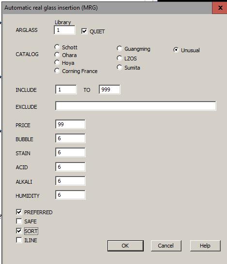
4 This is excellent! The wavefront errors are less than ¼ wave everywhere. Now it s time to switch to real glasses but first we change the material on surface 9 to the real glass that the customer wants to use: Hoya type BSC7. Since DSEARCH models the cover glass with a GLM material, that model would also be matched in the next step if we don t replace it now. To do so, we open the WorkSheet (WS) and click on surface 9 in the PAD window. Then we type in the edit pane 9 GTB H BSC7 click Update, and save a checkpoint. The model is replaced. Now we open the real-glass menu (MRG) and select the U catalog. That catalog does not have ordinary optical glasses -- but it does have the plastic materials. When you specify the U catalog, the ARG program (which is run from the MRG dialog) automatically selects only plastics and only replaces GLMs designated PLASTIC in the RLE file. It has two modes; it can replace the lenses in numerical order, or it can sort them so it replaces the ones furthest from a real material first. The second option is sometimes better, so we select Sort in the MRG dialog, select the Quiet option and then OK. Sometimes changing to a real glass causes ray failures. The program adjusts the curvatures to maintain element power, but if aspheric terms are present, some rays can still fail. If this happens, run ARG again after the other materials are changed. This usually works. Now there are real materials everywhere. Just to be sure we have an optimum design, we delete the GLM variables in the PANT file (or change them to a single VLIST GLM ALL, which only varies GLMs that are already in the lens), and optimize some more. 4
5 5

6 Here are the MTF curves for this design. It is close to perfect. Encore Well, that s a start, and now you understand how to use the program, but what could we have done differently? This design is at the diffraction limit, but the MTF at full field is much lower than on axis. Why is that? Well, since the lens has the stop in front and we are correcting distortion, the image necessarily shows cos**4 darkening. In fact, at a field angle of 41.3 degrees, that means the edge is just under 32% as bright as the center. How does nature manage to do that? By changing the effective F/number! We type the commands FN 0 FN 1 and see that while the on-axis F/number is indeed about 2.7, at the edge it is 5.2 in the tangential direction and 3.7 in the sagittal. The higher F/number increases the size of the Airy diffraction disk, which lowers the cutoff frequency in the Y direction. That is what the MTF curves tell us. If that situation is satisfactory, we are done. But let s assume you really want uniform illumination over the field. You can t get that unless you let the distortion grow. That may not be a problem if you plan to compensate electronically afterwards. Here s what to do: 6

7 1. Delete (or comment out) the lines in the SPECIAL AANT section of the DSEARCH input that gave targets to the chief-ray YA at three field points. SKIP M A P YA 1 M A P YA.7 M A P YA.4 EOS 2. Add some new requirements. These will control the relative illumination at five field points. M 1 1 A P ILLUM.2 M 1 1 A P ILLUM.4 M 1 1 A P ILLUM.6 M 1 1 A P ILLUM.8 M 1 1 A P ILLUM 1 3. Since the F/number at the edge of the field will now be smaller which is harder to correct, we increase the weights on the outer two fields from 1.0 to 2.0. Now run this version on DSEARCH, and the lens construction is very different. We optimize some more and notice that the upper rim ray at full field is rapidly flying away, so we add to the MF the line M 0.1 A P OPD and optimize again. Much better! Here is that lens, after optimization and inserting real plastics: 7


8 The MTF is quite good, as shown below. And the illumination is indeed almost perfectly uniform as plotted with the command ILLUM 500 P 8

9 The program has indeed introduced significant distortion. Here is the plot produced by the command GDIS 21 G Coda We made it look easy, and it is if you follow the steps above. But of course, lens design has pitfalls all over the place and things do not always work perfectly the first time. Here are some of the problems that you may encounter, and how to deal with them: 1. We specified an aspheric count of 4 in this example; that assigns terms up to R**10 to the surfaces. What happens if you use fewer or more terms than this? As a rule, it is better to start with a smaller number and then add more after you have optimized the result as well as possible. Too many terms right at the start can send the design to a region where the terms are fighting each other and become too large. Also, raytracing can prove a problem with many high-order terms, since the beam can exhibit caustics or large ray angles where you don t want them. We have obtained excellent results by starting with only two terms, and then adding more as we optimized the result. 9
10 2. Note that the FNUM request in the DSEARCH input file specified a weight of 10; this is more important than meets the eye. If we left the weighting factor off, the program would control the F/number exactly, with a paraxial solve which can lead to ray failures if the radius that results is too steep. So, for fast lenses such as this one, we usually add a weight. Then the program adds a requirement to the merit function to control the F/number, and the radius is given by the RSTART value. In the second example, where we did not target the image height, the F/number would probably have grown larger than the target value if we had assigned a lower weight. The program will do absolutely anything to reduce the merit function, and giving up a little on that score would likely bring down the other aberrations significantly, resulting in a great image at a higher F/number. So we specified a weight of 10 so that solution would not look so attractive. 3. Remember that DSEARCH uses the annealing feature (if you request it, which is nearly always a good idea), and that feature makes small random changes to the lens, over and over. This greatly improves the optimization of each case, but the results are not repeatable from run to run. For that reason, it is often a good idea to run DSEARCH more than once, and look at some of the other configurations it returns each time. We ran it several times for this lesson, and the results shown above were the best of the lot. 4. These designs met our goals very nicely. But suppose you don t want the cost of a fourelement lens. What can you do with three elements? Try it and find out! It will likely not be as good, but then, maybe you don t need that level of resolution with your sensor. This example uses plastics for all the lens elements except the cover glass. What if you want some elements to be made of glass and the others of plastic? Simple. Just declare which elements are of plastic in the DSEARCH input file, and the program will restrict them to the smaller range where plastics are to be found. Glass elements, on the other hand, will still be free to move over the usual range of the glass map. When the design is satisfactory and you run ARG, the program will match only the plastic elements if the U catalog is selected and will not match them with any other catalog. Simple indeed. 10
Lesson 16: A Practical Camera Lens
 Lesson 16: A Practical Camera Lens Global search for a camera lens design Although the lens we designed in Lesson 15 was pretty good, let us assume it was a little too long. To be practical, we would like
Lesson 26: Putting it All Together
 Lesson 26: Putting it All Together In this lesson we will undertake a rather difficult lens design task, one that will demonstrate some of the many powerful features that you have learned about in previous
Lesson 47. A 30X zoom lens
 Lesson 47. A 30X zoom lens Lesson 38 showed how to design an 8X zoom lens with no starting configuration. Now we will do a more difficult job, aiming for a zoom ratio of 30X. This exercise will use many
Lesson 7. The In and Out of Vignetting
 Lesson 7. The In and Out of Vignetting By vignetting we mean any property of a lens that reduces the size of the beam relative to the size that is sent in. It is a topic that different programs handle
Lesson 42. The In and Out of Vignetting
 Lesson 42. The In and Out of Vignetting By vignetting we mean any property of a lens that reduces the size of the beam relative to the size that is sent in. It is a topic that different programs handle
Lesson 31: The Superachromat
 Lesson 31: The Superachromat This lesson will explore a unique feature of SYNOPSYS that can be helpful when you need exceptional color correction, better even than an apochromat. Lesson 8 in this Online
Lesson 1: SYNOPSYS Examples the Apochromatic objective
 Lesson 1: SYNOPSYS Examples the Apochromatic objective This lesson shows how to design a lens with better color correction than one can get with a simple doublet. A concise description of how one can proceed
CODE V Introductory Tutorial
 CODE V Introductory Tutorial Cheng-Fang Ho Lab.of RF-MW Photonics, Department of Physics, National Cheng-Kung University, Tainan, Taiwan 1-1 Tutorial Outline Introduction to CODE V Optical Design Process
Lesson 6. The importance of Third-order Aberrations
 Lesson 6. The importance of Third-order Aberrations Many students of lens design, and many managers who hire lens designers, are adamant that aberrations have to be very well controlled. They are partly
ME 297 L4-2 Optical design flow Analysis
 ME 297 L4-2 Optical design flow Analysis Nayer Eradat Fall 2011 SJSU 1 Are we meeting the specs? First order requirements (after scaling the lens) Distortion Sharpness (diffraction MTF-will establish depth
Lesson 27: Understanding the Narcissus Effect
 Lesson 27: Understanding the Narcissus Effect Night-vision systems can see in total darkness. That works because all matter in the universe radiates energy in the form of photons, following the Planck
Exercises Advanced Optical Design Part 5 Solutions
 2014-12-09 Manuel Tessmer M.Tessmer@uni-jena.dee Minyi Zhong minyi.zhong@uni-jena.de Herbert Gross herbert.gross@uni-jena.de Friedrich Schiller University Jena Institute of Applied Physics Albert-Einstein-Str.
Performance Factors. Technical Assistance. Fundamental Optics
 Performance Factors After paraxial formulas have been used to select values for component focal length(s) and diameter(s), the final step is to select actual lenses. As in any engineering problem, this
Why is There a Black Dot when Defocus = 1λ?
 Why is There a Black Dot when Defocus = 1λ? W = W 020 = a 020 ρ 2 When a 020 = 1λ Sag of the wavefront at full aperture (ρ = 1) = 1λ Sag of the wavefront at ρ = 0.707 = 0.5λ Area of the pupil from ρ =
Chapter 3. Introduction to Zemax. 3.1 Introduction. 3.2 Zemax
 Chapter 3 Introduction to Zemax 3.1 Introduction Ray tracing is practical only for paraxial analysis. Computing aberrations and diffraction effects are time consuming. Optical Designers need some popular
Lens Design I Seminar 1
 Xiang Lu, Ralf Hambach Friedrich Schiller University Jena Institute of Applied Physics Albert-Einstein-Str 15 07745 Jena Lens Design I Seminar 1 Warm-Up (20min) Setup a single, symmetric, biconvex lens
Lens Design I. Lecture 5: Advanced handling I Herbert Gross. Summer term
 Lens Design I Lecture 5: Advanced handling I 2018-05-17 Herbert Gross Summer term 2018 www.iap.uni-jena.de 2 Preliminary Schedule - Lens Design I 2018 1 12.04. Basics 2 19.04. Properties of optical systems
CATALOG LENS USE IN OSLO
 CATALOG LENS USE IN OSLO Tutorial: A Catalog Galilean Telescope Richard N. Youngworth, Ph.D. - Presenter Tutorial example: creating a Galilean telescope from catalog lenses Start a new lens, pick a name
Optical Design with Zemax
 Optical Design with Zemax Lecture 9: Advanced handling 2014-06-13 Herbert Gross Sommer term 2014 www.iap.uni-jena.de 2 Preliminary Schedule 1 11.04. Introduction 2 25.04. Properties of optical systems
Opti 415/515. Introduction to Optical Systems. Copyright 2009, William P. Kuhn
 Opti 415/515 Introduction to Optical Systems 1 Optical Systems Manipulate light to form an image on a detector. Point source microscope Hubble telescope (NASA) 2 Fundamental System Requirements Application
Sequential Ray Tracing. Lecture 2
 Sequential Ray Tracing Lecture 2 Sequential Ray Tracing Rays are traced through a pre-defined sequence of surfaces while travelling from the object surface to the image surface. Rays hit each surface once
Computer exercise 2 geometrical optics and the telescope
 Computer exercise 2 geometrical optics and the telescope In this exercise, you will learn more of the tools included in Synopsys, including how to find system specifications such as focal length and F-number.
Optimisation. Lecture 3
 Optimisation Lecture 3 Objectives: Lecture 3 At the end of this lecture you should: 1. Understand the use of Petzval curvature to balance lens components 2. Know how different aberrations depend on field
Tolerancing in Zemax. Lecture 4
 Tolerancing in Zemax Lecture 4 Objectives: Lecture 4 At the end of this lecture you should: 1. Understand the reason for tolerancing and its relation to typical manufacturing errors 2. Be able to perform
ECEN 4606, UNDERGRADUATE OPTICS LAB
 ECEN 4606, UNDERGRADUATE OPTICS LAB Lab 2: Imaging 1 the Telescope Original Version: Prof. McLeod SUMMARY: In this lab you will become familiar with the use of one or more lenses to create images of distant
Advanced Lens Design
 Advanced Lens Design Lecture 3: Aberrations I 214-11-4 Herbert Gross Winter term 214 www.iap.uni-jena.de 2 Preliminary Schedule 1 21.1. Basics Paraxial optics, imaging, Zemax handling 2 28.1. Optical systems
Tutorial Zemax 9: Physical optical modelling I
 Tutorial Zemax 9: Physical optical modelling I 2012-11-04 9 Physical optical modelling I 1 9.1 Gaussian Beams... 1 9.2 Physical Beam Propagation... 3 9.3 Polarization... 7 9.4 Polarization II... 11 9 Physical
Advanced Lens Design
 Advanced Lens Design Lecture 4: Optimization III 2013-11-04 Herbert Gross Winter term 2013 www.iap.uni-jena.de 2 Preliminary Schedule 1 15.10. Introduction Paraxial optics, ideal lenses, optical systems,
Optical Design with Zemax for PhD
 Optical Design with Zemax for PhD Lecture 7: Optimization II 26--2 Herbert Gross Winter term 25 www.iap.uni-jena.de 2 Preliminary Schedule No Date Subject Detailed content.. Introduction 2 2.2. Basic Zemax
Tutorial Zemax 8: Correction II
 Tutorial Zemax 8: Correction II 2012-10-11 8 Correction II 1 8.1 High-NA Collimator... 1 8.2 Zoom-System... 6 8.3 New Achromate and wide field system... 11 8 Correction II 8.1 High-NA Collimator An achromatic
Using molded chalcogenide glass technology to reduce cost in a compact wide-angle thermal imaging lens
 Using molded chalcogenide glass technology to reduce cost in a compact wide-angle thermal imaging lens George Curatu a, Brent Binkley a, David Tinch a, and Costin Curatu b a LightPath Technologies, 2603
1.1 Singlet. Solution. a) Starting setup: The two radii and the image distance is chosen as variable.
 Starting setup: The two radii and the image distance is chosen as variable.") 1 1.1 Singlet Optimize a single lens with the data λ = 546.07 nm, object in the distance 100 mm from the lens on axis only, focal length f = 45 mm and numerical aperture NA = 0.07 in the object space.
1 1.1 Singlet Optimize a single lens with the data λ = 546.07 nm, object in the distance 100 mm from the lens on axis only, focal length f = 45 mm and numerical aperture NA = 0.07 in the object space.
Aberrations of a lens
 Aberrations of a lens 1. What are aberrations? A lens made of a uniform glass with spherical surfaces cannot form perfect images. Spherical aberration is a prominent image defect for a point source on
Some of the important topics needed to be addressed in a successful lens design project (R.R. Shannon: The Art and Science of Optical Design)
") Lens design Some of the important topics needed to be addressed in a successful lens design project (R.R. Shannon: The Art and Science of Optical Design) Focal length (f) Field angle or field size F/number
Lens design Some of the important topics needed to be addressed in a successful lens design project (R.R. Shannon: The Art and Science of Optical Design) Focal length (f) Field angle or field size F/number
Optical Design with Zemax
 Optical Design with Zemax Lecture : Correction II 3--9 Herbert Gross Summer term www.iap.uni-jena.de Correction II Preliminary time schedule 6.. Introduction Introduction, Zemax interface, menues, file
Optical Design with Zemax for PhD - Basics
 Optical Design with Zemax for PhD - Basics Lecture 3: Properties of optical sstems II 2013-05-30 Herbert Gross Summer term 2013 www.iap.uni-jena.de 2 Preliminar Schedule No Date Subject Detailed content
Criteria for Optical Systems: Optical Path Difference How do we determine the quality of a lens system? Several criteria used in optical design
 Criteria for Optical Systems: Optical Path Difference How do we determine the quality of a lens system? Several criteria used in optical design Computer Aided Design Several CAD tools use Ray Tracing (see
Devices & Services Company
 Devices & Services Company 10290 Monroe Drive, Suite 202 - Dallas, Texas 75229 USA - Tel. 214-902-8337 - Fax 214-902-8303 Web: www.devicesandservices.com Email: sales@devicesandservices.com D&S Technical
OSLO Doublet Optimization Tutorial
 OSLO Doublet Optimization Tutorial This tutorial helps optical designers with the most basic process for setting up a lens and optimizing in OSLO. The example intentionally goes through basics as well
Introductions to aberrations OPTI 517
 Introductions to aberrations OPTI 517 Lecture 11 Spherical aberration Meridional and sagittal ray fans Spherical aberration 0.25 wave f/10; f=100 mm; wave=0.0005 mm Spherical aberration 0.5 wave f/10;
12.4 Alignment and Manufacturing Tolerances for Segmented Telescopes
 330 Chapter 12 12.4 Alignment and Manufacturing Tolerances for Segmented Telescopes Similar to the JWST, the next-generation large-aperture space telescope for optical and UV astronomy has a segmented
AgilEye Manual Version 2.0 February 28, 2007
 AgilEye Manual Version 2.0 February 28, 2007 1717 Louisiana NE Suite 202 Albuquerque, NM 87110 (505) 268-4742 support@agiloptics.com 2 (505) 268-4742 v. 2.0 February 07, 2007 3 Introduction AgilEye Wavefront
Some lens design methods. Dave Shafer David Shafer Optical Design Fairfield, CT #
 Some lens design methods Dave Shafer David Shafer Optical Design Fairfield, CT 06824 #203-259-1431 shaferlens@sbcglobal.net Where do we find our ideas about how to do optical design? You probably won t
Lens Design I. Lecture 5: Advanced handling I Herbert Gross. Summer term
 Lens Design I Lecture 5: Advanced handling I 2015-05-11 Herbert Gross Summer term 2015 www.iap.uni-jena.de 2 Preliminary Schedule 1 13.04. Basics 2 20.04. Properties of optical systrems I 3 27.05. Properties
CHAPTER 33 ABERRATION CURVES IN LENS DESIGN
 CHAPTER 33 ABERRATION CURVES IN LENS DESIGN Donald C. O Shea Georgia Institute of Technology Center for Optical Science and Engineering and School of Physics Atlanta, Georgia Michael E. Harrigan Eastman
TECHSPEC COMPACT FIXED FOCAL LENGTH LENS
 Designed for use in machine vision applications, our TECHSPEC Compact Fixed Focal Length Lenses are ideal for use in factory automation, inspection or qualification. These machine vision lenses have been
 Telecentric Imaging Object space telecentricity stop source: edmund optics The 5 classical Seidel Aberrations First order aberrations Spherical Aberration (~r 4 ) Origin: different focal lengths for different
Chapter Ray and Wave Optics
 109 Chapter Ray and Wave Optics 1. An astronomical telescope has a large aperture to [2002] reduce spherical aberration have high resolution increase span of observation have low dispersion. 2. If two
Imaging Optics Fundamentals
 Imaging Optics Fundamentals Gregory Hollows Director, Machine Vision Solutions Edmund Optics Why Are We Here? Topics for Discussion Fundamental Parameters of your system Field of View Working Distance
Lens Design I. Lecture 3: Properties of optical systems II Herbert Gross. Summer term
 Lens Design I Lecture 3: Properties of optical systems II 207-04-20 Herbert Gross Summer term 207 www.iap.uni-jena.de 2 Preliminary Schedule - Lens Design I 207 06.04. Basics 2 3.04. Properties of optical
Exercise 1 - Lens bending
 Exercise 1 - Lens bending Most of the aberrations change with the bending of a lens. This is demonstrated in this exercise. a) Establish a lens with focal length f = 100 mm made of BK7 with thickness 5
Phys 531 Lecture 9 30 September 2004 Ray Optics II. + 1 s i. = 1 f
 Phys 531 Lecture 9 30 September 2004 Ray Optics II Last time, developed idea of ray optics approximation to wave theory Introduced paraxial approximation: rays with θ 1 Will continue to use Started disussing
Exam questions OPTI 517. Only a calculator and a single sheet of paper, 8 X11, with formulas will be allowed during the exam.
 Exam questions OPTI 517 Only a calculator an a single sheet of paper, 8 X11, with formulas will be allowe uring the exam. 1) A single optical spherical surface oes not contribute spherical aberration.
Typical requirements of passive mm-wave imaging systems, and consequences for antenna design
 Typical requirements of passive mm-wave imaging systems, and consequences for antenna design Rupert Anderton A presentation to: 6th Millimetre-wave Users Group NPL, Teddington 5 October 2009 1 1 Characteristics
Lecture 4: Geometrical Optics 2. Optical Systems. Images and Pupils. Rays. Wavefronts. Aberrations. Outline
 Lecture 4: Geometrical Optics 2 Outline 1 Optical Systems 2 Images and Pupils 3 Rays 4 Wavefronts 5 Aberrations Christoph U. Keller, Leiden University, keller@strw.leidenuniv.nl Lecture 4: Geometrical
Optical Systems: Pinhole Camera Pinhole camera: simple hole in a box: Called Camera Obscura Aristotle discussed, Al-Hazen analyzed in Book of Optics
 Optical Systems: Pinhole Camera Pinhole camera: simple hole in a box: Called Camera Obscura Aristotle discussed, Al-Hazen analyzed in Book of Optics 1011CE Restricts rays: acts as a single lens: inverts
Image Formation. Light from distant things. Geometrical optics. Pinhole camera. Chapter 36
 Light from distant things Chapter 36 We learn about a distant thing from the light it generates or redirects. The lenses in our eyes create images of objects our brains can process. This chapter concerns
IMAGE SENSOR SOLUTIONS. KAC-96-1/5" Lens Kit. KODAK KAC-96-1/5" Lens Kit. for use with the KODAK CMOS Image Sensors. November 2004 Revision 2
 KODAK for use with the KODAK CMOS Image Sensors November 2004 Revision 2 1.1 Introduction Choosing the right lens is a critical aspect of designing an imaging system. Typically the trade off between image
Be aware that there is no universal notation for the various quantities.
 Fourier Optics v2.4 Ray tracing is limited in its ability to describe optics because it ignores the wave properties of light. Diffraction is needed to explain image spatial resolution and contrast and
Optical System Design
 Phys 531 Lecture 12 14 October 2004 Optical System Design Last time: Surveyed examples of optical systems Today, discuss system design Lens design = course of its own (not taught by me!) Try to give some
Mirrors and Lenses. Images can be formed by reflection from mirrors. Images can be formed by refraction through lenses.
 Mirrors and Lenses Images can be formed by reflection from mirrors. Images can be formed by refraction through lenses. Notation for Mirrors and Lenses The object distance is the distance from the object
Lens Design II Seminar 6 (Solutions)
") 2017-01-04 Prof. Herbert Gross Yi Zhong, Norman G. Worku Friedrich Schiller University Jena Institute of Applied Physics Albert-Einstein-Str 15 07745 Jena Lens Design II Seminar 6 (Solutions) 6.1. Correction
2017-01-04 Prof. Herbert Gross Yi Zhong, Norman G. Worku Friedrich Schiller University Jena Institute of Applied Physics Albert-Einstein-Str 15 07745 Jena Lens Design II Seminar 6 (Solutions) 6.1. Correction
ECEG105/ECEU646 Optics for Engineers Course Notes Part 4: Apertures, Aberrations Prof. Charles A. DiMarzio Northeastern University Fall 2008
 ECEG105/ECEU646 Optics for Engineers Course Notes Part 4: Apertures, Aberrations Prof. Charles A. DiMarzio Northeastern University Fall 2008 July 2003+ Chuck DiMarzio, Northeastern University 11270-04-1
PROCEEDINGS OF SPIE. Automated asphere centration testing with AspheroCheck UP
 PROCEEDINGS OF SPIE SPIEDigitalLibrary.org/conference-proceedings-of-spie Automated asphere centration testing with AspheroCheck UP F. Hahne, P. Langehanenberg F. Hahne, P. Langehanenberg, "Automated asphere
3.0 Alignment Equipment and Diagnostic Tools:
 3.0 Alignment Equipment and Diagnostic Tools: Alignment equipment The alignment telescope and its use The laser autostigmatic cube (LACI) interferometer A pin -- and how to find the center of curvature
Tolerancing in Zemax
 Tolerancing in Zemax Rachel Haynes Opti 521 Tutorial December 10, 2007 Introduction Being able to design a good optical system is important as an optical engineer, but equally as important is being able
Lens Design I. Lecture 10: Optimization II Herbert Gross. Summer term
 Lens Design I Lecture : Optimization II 8-6- Herbert Gross Summer term 8 www.iap.uni-jena.de Preliminary Schedule - Lens Design I 8.4. Basics 9.4. Properties of optical systems I 3 6.4. Properties of optical
Use of Mangin and aspheric mirrors to increase the FOV in Schmidt- Cassegrain Telescopes
 Use of Mangin and aspheric mirrors to increase the FOV in Schmidt- Cassegrain Telescopes A. Cifuentes a, J. Arasa* b,m. C. de la Fuente c, a SnellOptics, Prat de la Riba, 35 local 3, Interior Terrassa
CODE V Tolerancing: A Key to Product Cost Reduction
 CODE V Tolerancing: A Key to Product Cost Reduction A critical step in the design of an optical system destined to be manufactured is to define a fabrication and assembly tolerance budget and to accurately
Lens Design I. Lecture 3: Properties of optical systems II Herbert Gross. Summer term
 Lens Design I Lecture 3: Properties of optical systems II 205-04-8 Herbert Gross Summer term 206 www.iap.uni-jena.de 2 Preliminary Schedule 04.04. Basics 2.04. Properties of optical systrems I 3 8.04.
Introductory Exercise - Landscape Lens
 Introductory Exercise - Landscape Lens INTRODUCTION This is a very basic tutorial that covers how to enter lens data in OSLO and perform a simple optimization. The end of this tutorial describes how to
Solutions: Lens Design I Part 2. Exercise 2-1: Apertures, stops and vignetting
 2016-04-25 Prof. Herbert Gross Mateusz Oleszko, Norman G. Worku Friedrich Schiller University Jena Institute of Applied Physics Albert-Einstein-Str 15 07745 Jena Solutions: Lens Design I Part 2 Exercise
Physics 142 Lenses and Mirrors Page 1. Lenses and Mirrors. Now for the sequence of events, in no particular order. Dan Rather
 Physics 142 Lenses and Mirrors Page 1 Lenses and Mirrors Now or the sequence o events, in no particular order. Dan Rather Overview: making use o the laws o relection and reraction We will now study ormation
Laboratory experiment aberrations
 Laboratory experiment aberrations Obligatory laboratory experiment on course in Optical design, SK2330/SK3330, KTH. Date Name Pass Objective This laboratory experiment is intended to demonstrate the most
Big League Cryogenics and Vacuum The LHC at CERN
 Big League Cryogenics and Vacuum The LHC at CERN A typical astronomical instrument must maintain about one cubic meter at a pressure of
Cardinal Points of an Optical System--and Other Basic Facts
 Cardinal Points of an Optical System--and Other Basic Facts The fundamental feature of any optical system is the aperture stop. Thus, the most fundamental optical system is the pinhole camera. The image
Introduction to Optical Modeling. Friedrich-Schiller-University Jena Institute of Applied Physics. Lecturer: Prof. U.D. Zeitner
 Introduction to Optical Modeling Friedrich-Schiller-University Jena Institute of Applied Physics Lecturer: Prof. U.D. Zeitner The Nature of Light Fundamental Question: What is Light? Newton Huygens / Maxwell
Lens Design I. Lecture 10: Optimization II Herbert Gross. Summer term
 Lens Design I Lecture : Optimization II 5-6- Herbert Gross Summer term 5 www.iap.uni-jena.de Preliminary Schedule 3.. Basics.. Properties of optical systrems I 3 7.5..5. Properties of optical systrems
Evaluation of Performance of the Toronto Ultra-Cold Atoms Laboratory s Current Axial Imaging System
 Page 1 5/7/2007 Evaluation of Performance of the Toronto Ultra-Cold Atoms Laboratory s Current Axial Imaging System Vincent Kan May 7, 2007 University of Toronto Department of Physics Supervisor: Prof.
Tutorial Zemax 3 Aberrations
 Tutorial Zemax 3 Aberrations 2012-08-14 3 Aberrations 1 3.1 Exercise 3-1: Strehl ratio and geometrical vs Psf spot size... 1 3.2 Exercise 3-2: Performance of an achromate... 3 3.3 Exercise 3-3: Anamorphotic
TESTING VISUAL TELESCOPIC DEVICES
 TESTING VISUAL TELESCOPIC DEVICES About Wells Research Joined TRIOPTICS mid 2012. Currently 8 employees Product line compliments TRIOPTICS, with little overlap Entry level products, generally less expensive
Optical Design Lab Suresh Sivanandam Dunlap Institute for Astronomy and Astrophysics, University of Toronto
 Optical Design Lab Suresh Sivanandam (sivanandam@dunlap.utoronto.ca) Dunlap Institute for Astronomy and Astrophysics, 1.Introduction and Objective Optical design is a critical part of astronomical instrument
Optics: An Introduction
 It is easy to overlook the contribution that optics make to a system; beyond basic lens parameters such as focal distance, the details can seem confusing. This Tech Tip presents a basic guide to optics
Telephoto axicon ABSTRACT
 Telephoto axicon Anna Burvall, Alexander Goncharov, and Chris Dainty Applied Optics, Department of Experimental Physics National University of Ireland, Galway, Ireland ABSTRACT The axicon is an optical
Geometric optics & aberrations
 Geometric optics & aberrations Department of Astrophysical Sciences University AST 542 http://www.northerneye.co.uk/ Outline Introduction: Optics in astronomy Basics of geometric optics Paraxial approximation
Testing Aspheric Lenses: New Approaches
 Nasrin Ghanbari OPTI 521 - Synopsis of a published Paper November 5, 2012 Testing Aspheric Lenses: New Approaches by W. Osten, B. D orband, E. Garbusi, Ch. Pruss, and L. Seifert Published in 2010 Introduction
Cameras. Steve Rotenberg CSE168: Rendering Algorithms UCSD, Spring 2017
 Cameras Steve Rotenberg CSE168: Rendering Algorithms UCSD, Spring 2017 Camera Focus Camera Focus So far, we have been simulating pinhole cameras with perfect focus Often times, we want to simulate more
QUICKSTART COURSE - MODULE 7 PART 3
 QUICKSTART COURSE - MODULE 7 PART 3 copyright 2011 by Eric Bobrow, all rights reserved For more information about the QuickStart Course, visit http://www.acbestpractices.com/quickstart Hello, this is Eric
CHAPTER 36 TOLERANCING TECHNIQUES
 CHAPTER 36 TOLERANCING TECHNIQUES Robert R. Shannon Optical Sciences Center Uni ersity of Arizona Tucson, Arizona 3 6. 1 GLOSSARY a relative tolerance error BK7, SF2 types of optical glass C to F spectral
Optical Design of an Off-axis Five-mirror-anastigmatic Telescope for Near Infrared Remote Sensing
 Journal of the Optical Society of Korea Vol. 16, No. 4, December 01, pp. 343-348 DOI: http://dx.doi.org/10.3807/josk.01.16.4.343 Optical Design of an Off-axis Five-mirror-anastigmatic Telescope for Near
Modulation Transfer Function
 Modulation Transfer Function The Modulation Transfer Function (MTF) is a useful tool in system evaluation. t describes if, and how well, different spatial frequencies are transferred from object to image.
ScanArray Overview. Principle of Operation. Instrument Components
 ScanArray Overview The GSI Lumonics ScanArrayÒ Microarray Analysis System is a scanning laser confocal fluorescence microscope that is used to determine the fluorescence intensity of a two-dimensional
Exam Preparation Guide Geometrical optics (TN3313)
") Exam Preparation Guide Geometrical optics (TN3313) Lectures: September - December 2001 Version of 21.12.2001 When preparing for the exam, check on Blackboard for a possible newer version of this guide.
Exam Preparation Guide Geometrical optics (TN3313) Lectures: September - December 2001 Version of 21.12.2001 When preparing for the exam, check on Blackboard for a possible newer version of this guide.
Using Optics to Optimize Your Machine Vision Application
 Expert Guide Using Optics to Optimize Your Machine Vision Application Introduction The lens is responsible for creating sufficient image quality to enable the vision system to extract the desired information
October 7, Peter Cheimets Smithsonian Astrophysical Observatory 60 Garden Street, MS 5 Cambridge, MA Dear Peter:
 October 7, 1997 Peter Cheimets Smithsonian Astrophysical Observatory 60 Garden Street, MS 5 Cambridge, MA 02138 Dear Peter: This is the report on all of the HIREX analysis done to date, with corrections
Lecture 2: Geometrical Optics. Geometrical Approximation. Lenses. Mirrors. Optical Systems. Images and Pupils. Aberrations.
 Lecture 2: Geometrical Optics Outline 1 Geometrical Approximation 2 Lenses 3 Mirrors 4 Optical Systems 5 Images and Pupils 6 Aberrations Christoph U. Keller, Leiden Observatory, keller@strw.leidenuniv.nl
Technical Note How to Compensate Lateral Chromatic Aberration
 Lateral Chromatic Aberration Compensation Function: In JAI color line scan cameras (3CCD/4CCD/3CMOS/4CMOS), sensors and prisms are precisely fabricated. On the other hand, the lens mounts of the cameras
Long Wave Infrared Scan Lens Design And Distortion Correction
 Long Wave Infrared Scan Lens Design And Distortion Correction Item Type text; Electronic Thesis Authors McCarron, Andrew Publisher The University of Arizona. Rights Copyright is held by the author. Digital
MASSACHUSETTS INSTITUTE OF TECHNOLOGY Department of Electrical Engineering and Computer Science
 Student Name Date MASSACHUSETTS INSTITUTE OF TECHNOLOGY Department of Electrical Engineering and Computer Science 6.161 Modern Optics Project Laboratory Laboratory Exercise No. 3 Fall 2005 Diffraction
5.0 NEXT-GENERATION INSTRUMENT CONCEPTS
 5.0 NEXT-GENERATION INSTRUMENT CONCEPTS Studies of the potential next-generation earth radiation budget instrument, PERSEPHONE, as described in Chapter 2.0, require the use of a radiative model of the