Akinori Mitani and Geoff Weiner BGGN 266 Spring 2013 Non-linear optics final report. Introduction and Background
|
|
|
- Victoria Hancock
- 6 years ago
- Views:
Transcription
1 Akinori Mitani and Geoff Weiner BGGN 266 Spring 2013 Non-linear optics final report Introduction and Background Two-photon microscopy is a type of fluorescence microscopy using two-photon excitation. It has been widely used in neuroscience because it can image internal structures of the brain at fine resolution. Principle of fluorescence microscopy Molecules emits fluorescence are called fluorophores. These molecules have multiple electron orbits, which is approximately spaced by the energy of a photon of visible light. The electrons of fluorophores are usually in low-energy orbits, but they go into high-energy orbits by absorbing a photon. The probability of absorption depends on the wavelength, which is called excitation spectrum. After absorbing a photon, first the electron relaxes to other orbits with slightly lower energy, and then goes back to the lower-energy orbits by emitting light. The wavelength of emission is probabilistic, and follows emission spectrum. Importantly, emission spectrum has longer wavelength than excitation spectrum because of the relaxation before going back to the lower-energy orbits. Using dichrotics to dissociate excitation and emission wavelength, fluorescence microscopy can achieve higher contrast than the conventional microscopy using the same wavelength of light. In addition, the excitation and emission spectrum is specific to a fluorophore, which also leads to higher contrast. Two-photon microscopy Instead of using a light within the excitation spectrum, two-photon microscopy utilizes a light with twice as long wavelength. Two photons with half energy can be simultaneously absorbed by a fluorophore to elicit fluorescence. As the probability of this phenomena is proportional to square of the light intensity, the intensity of fluorescence emission drops biquadratically to the distance from the focal plane, which is faster than quadratic decrease of single-photon excitation. With this smaller focal volume, an image with finer resolution can be obtained. Furthermore, a light with longer wavelength is less scattered, which enables imaging deeper planes of the tissue. Methods System overview
2 We followed closely the design principles previously described (Tsai and Kleinfeld, 2009, overview shown in Figure 1). Briefly, a Ti:sapphire laser was pumped and mode-locked to emit a spectrum of light centered at 780nm. An optical path was designed that split the 500mW beam into two beams so that another group could construct a similar system in tandem. The beam was then wrapped around a vertical tower via a system of mirrors. A set of scanning mirrors directed the beam down through a series of lenses to expand the beam in order to completely fill the back aperture of the objective. Light was collected from a sample through the objective, reflected off a dichroic, passed through lenses, and directed into a photomultiplier tube (PMT). The PMT signal was converted to a voltage signal, and read out by a data acquisition board into a PC computer running custom imaging software. PMT collection lens sample dichroic tube lens scan lens scanning mirrors Laser Figure 1 System overview. Dashed lines indicate optical path. Solid lines indicate reflective surfaces (mirrors or dichroics). Laser and optical path We used a Spectra Physics Millenia V diode-dumped, CW visible laser to pump a spectra Physics Mode-locked Ti:sapphire laser. The difference in intensity profile between a mode-locked and non-mode locked laser is significant (see Troubleshooting section for more information on mode-locking and Figure 2).
.")
3 Figure 2 Laser mode-locking. (Top) Laser not mode-locked. Intensity distribution is peaked. (Bottom) Mode-locked laser displaying significantly broadened intensity distribution. The power of the laser drops off as it traverses the optical path (see Troubleshooting section for more information on losing beam power across the scanning mirrors, and Figure 3). The path was sequentially aligned using a twomirror two-aperture method to center the beam on the succeeding point in the pathway. The proximal mirror was used to fit the beam through the proximal pinhole and the distal mirror was used to fit the beam through the distal pinhole. After bringing the beam to the top of a vertical tower it was bent at 90 degrees by the scanning mirror system. It then passed though a scan lens (focal length 50.8mm) and a tube lens (focal length 76.2mm), the purpose of which were to collimate the beam for an infinity-corrected 20X Ph1 Zeiss water-immersion objective. The constraints on path length and the placement of the objective and lenses is previously described (Tsai and Kleinfeld, 2009) but briefly, the scan lens is placed to optimally expand the beam, the tube lens collimates the beam coming out of the scan lens, and together they create an imaging condition between the scan mirror and the back aperture of the objective. Optimal expansion of the beam depends on the diameter of the back aperture and the characteristics of the beam, which is Gaussian in its intensity profile. Ideally the
4 full width at half maximum is taken as the diameter of the beam, which is then expanded to slightly overfill the back aperture scanning mirrors Laser 100 Figure 3 Percentage of maximal intensity of laser beam at different points along the optical path (normalized to 100 at the laser outlet). Measured by a handheld Coherent FieldMate Laser Power Meter. Epi-fluorescence collection is used to direct light from the sample to the PMT. Collected light is collimated coming out of the objective, and reflected off of a dichroic that passes excitation wavelengths down to the sample and reflects emission wavelengths towards the detector apparatus. It passed through a collection lens (focal length 50.2mm), the purpose of which is to create an imaging condition between the back aperture of the objective and the active surface of the PMT, as well as to magnify the beam to fit the active surface of the PMT. In our system, given our lens setup, beam profile, and detector sizes, the path length from back aperture to collection lens was 101.6mm and from collection lens to detector was 6.5mm. Scanning system We used a set of open-loop X-Y scanners from Midwest Laser to complete X-Y scanning. Initially we assumed that these were silvered mirrors, but later learned that they are dielectric mirrors (see Troubleshooting section for more information). Each mirror had its own control board, which was powered by a custom power box Figure 4A), and received analog inputs from a National Instruments (NI) BNC-2090 attached to a PC. Output control from the PC was done through the custom program MPScope 2.0 (Figure 4B). Adjusting the Maximal Mirror Command Voltage changed the amplitude of the scan, and adjusting the frame rate or magnification changed the speed of the scan.


 I to V converter and pre-amplifier that")
5 A B C D Figure 4 Custom electronics and software. (A) Power supply to drive the actuators in the scanning mirrors. (B) Screen shot of MPScope 2.0 showing at example of a real-time image. (C) Power supply for the PMT. (D) I to V converter and pre-amplifier that sits between the PMT and the data acquisition board. Detection electronics and software
6 We used a Hamamatsu GaAsP H7422 PMT for epi-fluorescence detection and powered it with a custom power supply (Figure 4C). A laser-blocking filter was mounted on the detector to reduce background from scattered photons. The PMT output was fed into a custom I-to-V converter box (see Troubleshooting section for more information and Figure 4D), where it was also amplified, and then into the same NI BNC-2090 and PC computer. The output was read out by MPScope and displayed in a window that allowed real-time manipulation of the image (Figure 4A). Sample preparation We prepared a sample for testing the microscope using thin lens paper, which has a fine microstructure clearly visible under 20X and 40X objectives. The paper was dipped in fluorescein, which should emit fluorescence with two-photon excitation in the nm range. The fluorescein paper was then placed under a 1.5 coverslip on a glass slide and sealed with nail polish. The paper must be dry after dipping in fluorescein so that the fluorescein molecules are forced to adhere to the paper and not remain dissolved in water. Results Two-photon fluorescence from fluorescein We succeeded in taking an image of a lens paper with fluorescein dye (Figure 5).

7 Figure 5 Image of a lens paper with fluorescein dye taken with two-photon excitation microscopy. Discussion/Troubleshooting Finally we could image the fibers of a paper with our two-photon microscope. At least at the center of the image, we could identify each fiber. However, the signal intensity and the contrast dropped rapidly at the peripheral of the image. We could not completely solve this problem, but this could be partly because of misalignment in the optical path. For example, if the back aperture of the objective is not exactly at the imaging plane of the scanning mirrors, the laser moves around and does not fill the back aperture properly when imaging peripheral pixels. The same could happen when the PMT is not at the image of the back aperture. Here are some other problems and solutions we came up with during setting up the system: 1. Mirrors/pinholes were not fixed properly.

8 Optical path alignment requires sequential alignment of mirrors. One day after finished the alignment, we noticed the first few mirrors and pinholes were loose. We had to tighten them and align the rest again. 2. Battery of laser pointer was not easy to remove. The laser pointers used for alignment require two AA batteries. The second one was not easy to replace. We taped the two batteries together so that they come out together. 3. Some parts required metric screws. We had to be careful not to use different screws. 4. Scanning mirror was broken. It worked properly at the beginning, but failed to work at high frequencies. We had to replace the scanning mirror. The broken one was labeled as broken. 5. I-V converter had too long time constant. First, the image taken had horizontal lines (Figure 6). This might be because the I-V converter had too long time constant and blurred the image along the axis of scanning. We replaced the I-V converter box. Figure 6 Example image taken with a improper I-V converter. 6. Dichroic mirror was not reflecting fluorescence. After we switched from single-photon setup with green-laser pointer to two-photon setup with Ti:Sapphire laser, we had to switch to a different dichroic mirror because the wavelength was different. 7. Scanning mirror was not reflecting laser. Because the scanning mirrors were not silvered mirrors but dielectic mirros, they did not reflect the infrared laser properly, and large portion of the laser power was lost through the mirrors. To compensate that, we took out the beam splitter and used all the laser power in this setup rather than sharing a laser with the other group. 8. Laser was not mode-locked properly. Sometimes the laser turned to be not mode-locked. We had to monitor the spectrum regularly to make sure it is mode-locked.

9 References In vivo two-photon laser scanning microscopy with concurrent plasma-mediated ablation: Principles and hardware realization. P. S. Tsai and D. Kleinfeld. In Methods for In Vivo Optical Imaging, Second Edition, R. Frostig, editor, 2009, CRC Press, 3: Appendix I Pictures of the completed system
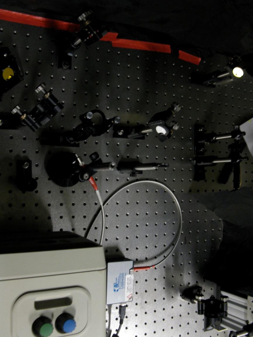
10
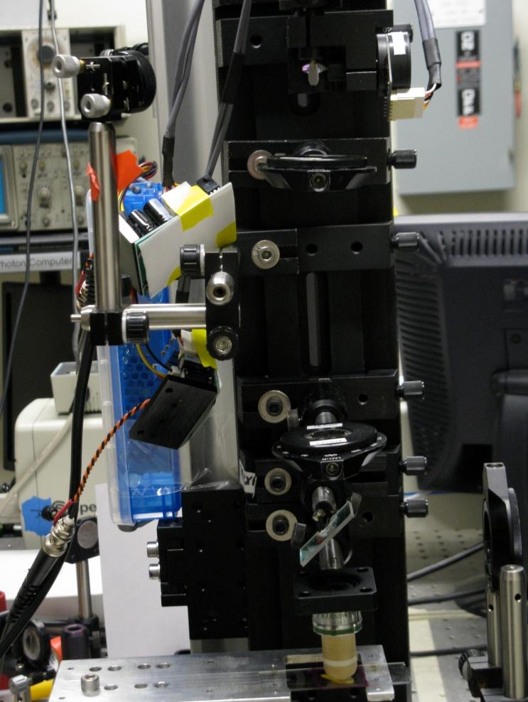
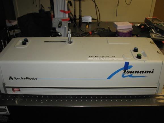
11
TRAINING MANUAL. Multiphoton Microscopy LSM 510 META-NLO
 TRAINING MANUAL Multiphoton Microscopy LSM 510 META-NLO September 2010 Multiphoton Microscopy Training Manual Multiphoton microscopy is only available on the LSM 510 META-NLO system. This system is equipped
Non-Descanned FLIM Detection in Multiphoton Microscopes
 Non-Descanned FLIM Detection in Multiphoton Microscopes Abstract. Multiphoton microscopes use a femtosecond NIR laser to excite fluorescence in the sample. Excitation is performed via a multi-photon absorption
Things to check before start-up.
 Byeong Cha Page 1 11/24/2009 Manual for Leica SP2 Confocal Microscope Enter you name, the date, the time, and the account number in the user log book. Things to check before start-up. Make sure that your
In Vivo Two-Photon Laser Scanning Microscopy with Concurrent Plasma- Mediated Ablation
 3 In Vivo Two-Photon Laser Scanning Microscopy with Concurrent Plasma- Mediated Ablation Principles and Hardware Realization Philbert S. Tsai and David Kleinfeld Contents 3.1 Introduction... 61 3. Overview...
Operation Guide for the Leica SP2 Confocal Microscope Bio-Imaging Facility Hunter College October 2009
 Operation Guide for the Leica SP2 Confocal Microscope Bio-Imaging Facility Hunter College October 2009 Introduction of Fluoresence Confocal Microscopy The first confocal microscope was invented by Princeton
Supplementary Materials
 Supplementary Materials In the supplementary materials of this paper we discuss some practical consideration for alignment of optical components to help unexperienced users to achieve a high performance
How to align your laser for two-photon imaging
 How to align your laser for two-photon imaging Two-photon microscopy uses a laser to excite fluorescent molecules (fluorophores) within a sample through emitting short pulses of light at high power. This
BASICS OF CONFOCAL IMAGING (PART I)
") BASICS OF CONFOCAL IMAGING (PART I) INTERNAL COURSE 2012 LIGHT MICROSCOPY Lateral resolution Transmission Fluorescence d min 1.22 NA obj NA cond 0 0 rairy 0.61 NAobj Ernst Abbe Lord Rayleigh Depth of field
BASICS OF CONFOCAL IMAGING (PART I) INTERNAL COURSE 2012 LIGHT MICROSCOPY Lateral resolution Transmission Fluorescence d min 1.22 NA obj NA cond 0 0 rairy 0.61 NAobj Ernst Abbe Lord Rayleigh Depth of field
Leica TCS SP8 Quick Start Guide
 Leica TCS SP8 Quick Start Guide Leica TCS SP8 System Overview Start-Up Procedure 1. Turn on the CTR Control Box, Fluorescent Light for the microscope stand. 2. Turn on the Scanner Power (1) on the front
Practical work no. 3: Confocal Live Cell Microscopy
 Practical work no. 3: Confocal Live Cell Microscopy Course Instructor: Mikko Liljeström (MIU) 1 Background Confocal microscopy: The main idea behind confocality is that it suppresses the signal outside
You won t be able to measure the incident power precisely. The readout of the power would be lower than the real incident power.
 1. a) Given the transfer function of a detector (below), label and describe these terms: i. dynamic range ii. linear dynamic range iii. sensitivity iv. responsivity b) Imagine you are using an optical
Boulevard du Temple Daguerrotype (Paris,1838) a busy street? Nyquist sampling for movement
 a busy street? Nyquist sampling for movement") Boulevard du Temple Daguerrotype (Paris,1838) a busy street? Nyquist sampling for movement CONFOCAL MICROSCOPY BioVis Uppsala, 2017 Jeremy Adler Matyas Molnar Dirk Pacholsky Widefield & Confocal Microscopy
Boulevard du Temple Daguerrotype (Paris,1838) a busy street? Nyquist sampling for movement CONFOCAL MICROSCOPY BioVis Uppsala, 2017 Jeremy Adler Matyas Molnar Dirk Pacholsky Widefield & Confocal Microscopy
Maria Smedh, Centre for Cellular Imaging. Maria Smedh, Centre for Cellular Imaging
 Nonlinear microscopy I: Two-photon fluorescence microscopy Multiphoton Microscopy What is multiphoton imaging? Applications Different imaging modes Advantages/disadvantages Scattering of light in thick
MULTIPHOTON MICROSCOPY. Matyas Molnar Dirk Pacholsky
 MULTIPHOTON MICROSCOPY Matyas Molnar Dirk Pacholsky Information Information given here about 2 Photon microscopy were mainly taken from these sources: Background information on 2-Photon microscopy: http://micro.magnet.fsu.edu/primer/techniques/fluorescence/multiphoton/
Imaging Beyond the Basics: Optimizing Settings on the Leica SP8 Confocal
 Imaging Beyond the Basics: Optimizing Settings on the Leica SP8 Confocal Todays Goal: Introduce some additional functionalities of the Leica SP8 confocal HyD vs. PMT detectors Dye Assistant Scanning By
Examination, TEN1, in courses SK2500/SK2501, Physics of Biomedical Microscopy,
 KTH Applied Physics Examination, TEN1, in courses SK2500/SK2501, Physics of Biomedical Microscopy, 2009-06-05, 8-13, FB51 Allowed aids: Compendium Imaging Physics (handed out) Compendium Light Microscopy
Characteristics of point-focus Simultaneous Spatial and temporal Focusing (SSTF) as a two-photon excited fluorescence microscopy
 as a two-photon excited fluorescence microscopy") Characteristics of point-focus Simultaneous Spatial and temporal Focusing (SSTF) as a two-photon excited fluorescence microscopy Qiyuan Song (M2) and Aoi Nakamura (B4) Abstracts: We theoretically and experimentally
Characteristics of point-focus Simultaneous Spatial and temporal Focusing (SSTF) as a two-photon excited fluorescence microscopy Qiyuan Song (M2) and Aoi Nakamura (B4) Abstracts: We theoretically and experimentally
The Zeiss AiryScan System, Confocal Four.
 The Zeiss AiryScan System, Confocal Four. Overview. The Zeiss AiryScan module is a segmented, radially stacked GaASP detector and collector system designed to subsample the airy disk of a point emission
Basics of confocal imaging (part I)
") Basics of confocal imaging (part I) Swiss Institute of Technology (EPFL) Faculty of Life Sciences Head of BIOIMAGING AND OPTICS BIOP arne.seitz@epfl.ch Lateral resolution BioImaging &Optics Platform Light
Basics of confocal imaging (part I) Swiss Institute of Technology (EPFL) Faculty of Life Sciences Head of BIOIMAGING AND OPTICS BIOP arne.seitz@epfl.ch Lateral resolution BioImaging &Optics Platform Light
Training Guide for Leica SP8 Confocal/Multiphoton Microscope
 Training Guide for Leica SP8 Confocal/Multiphoton Microscope LAS AF v3.3 Optical Imaging & Vital Microscopy Core Baylor College of Medicine (2017) Power ON Routine 1 2 Turn ON power switch for epifluorescence
Be aware that there is no universal notation for the various quantities.
 Fourier Optics v2.4 Ray tracing is limited in its ability to describe optics because it ignores the wave properties of light. Diffraction is needed to explain image spatial resolution and contrast and
Why and How? Daniel Gitler Dept. of Physiology Ben-Gurion University of the Negev. Microscopy course, Michmoret Dec 2005
 Why and How? Daniel Gitler Dept. of Physiology Ben-Gurion University of the Negev Why use confocal microscopy? Principles of the laser scanning confocal microscope. Image resolution. Manipulating the
Imaging Retreat - UMASS Customized real-time confocal and 2-photon imaging
 Imaging Retreat - UMASS 2012 Customized real-time confocal and 2-photon imaging Mike Sanderson Department of Microbiology and Physiological Systems University of Massachusetts Medical School Thanks for
Quick Start Guide. Leica SP5 X
 Quick Start Guide Leica SP5 X Please note: Some of the information in this guide was taken from Leica Microsystems Leica TCS SP5 LAS AF Guide for New Users. This work is licensed under the Creative Commons
Digital Camera Technologies for Scientific Bio-Imaging. Part 2: Sampling and Signal
 Digital Camera Technologies for Scientific Bio-Imaging. Part 2: Sampling and Signal Yashvinder Sabharwal, 1 James Joubert 2 and Deepak Sharma 2 1. Solexis Advisors LLC, Austin, TX, USA 2. Photometrics
Zeiss LSM 510 Confocor III Training Notes. Center for Cell Analysis & Modeling
 Zeiss LSM 510 Confocor III Training Notes Center for Cell Analysis & Modeling Confocor 3 Start Up Go to System Module Turn on Main Switch, System/ PC, and Components Switches Do you need the arc lamp?
MASSACHUSETTS INSTITUTE OF TECHNOLOGY Department of Electrical Engineering and Computer Science
 Student Name Date MASSACHUSETTS INSTITUTE OF TECHNOLOGY Department of Electrical Engineering and Computer Science 6.161 Modern Optics Project Laboratory Laboratory Exercise No. 6 Fall 2010 Solid-State
Supplemental Figure 1: Histogram of 63x Objective Lens z axis Calculated Resolutions. Results from the MetroloJ z axis fits for 5 beads from each
 Supplemental Figure 1: Histogram of 63x Objective Lens z axis Calculated Resolutions. Results from the MetroloJ z axis fits for 5 beads from each lens with a 1 Airy unit pinhole setting. Many water lenses
3D light microscopy techniques
 3D light microscopy techniques The image of a point is a 3D feature In-focus image Out-of-focus image The image of a point is not a point Point Spread Function (PSF) 1D imaging 1 1 2! NA = 0.5! NA 2D imaging
Zeiss 880 Training Notes Zen 2.3
 Zeiss 880 Training Notes Zen 2.3 1 Turn on the HXP 120V Lamp 2 Turn on Main Power Switch Turn on the Systems PC Switch Turn on the Components Switch. 3 4 5 Turn on the PC and log into your account. Start
Spectral phase shaping for high resolution CARS spectroscopy around 3000 cm 1
 Spectral phase shaping for high resolution CARS spectroscopy around 3 cm A.C.W. van Rhijn, S. Postma, J.P. Korterik, J.L. Herek, and H.L. Offerhaus Mesa + Research Institute for Nanotechnology, University
In Vivo Two-Photon Laser Scanning Microscopy with Concurrent Plasma-Mediated Ablation Principles and Hardware Realization - In Vivo Op...
 NCBI Bookshelf. A service of the National Library of Medicine, National Institutes of Health. Frostig RD, editor. In Vivo Optical Imaging of Brain Function. 2nd edition. Boca Raton (FL): CRC Press/Taylor
Spectroscopy of Ruby Fluorescence Physics Advanced Physics Lab - Summer 2018 Don Heiman, Northeastern University, 1/12/2018
 1 Spectroscopy of Ruby Fluorescence Physics 3600 - Advanced Physics Lab - Summer 2018 Don Heiman, Northeastern University, 1/12/2018 I. INTRODUCTION The laser was invented in May 1960 by Theodor Maiman.
Point Spread Function. Confocal Laser Scanning Microscopy. Confocal Aperture. Optical aberrations. Alternative Scanning Microscopy
 Bi177 Lecture 5 Adding the Third Dimension Wide-field Imaging Point Spread Function Deconvolution Confocal Laser Scanning Microscopy Confocal Aperture Optical aberrations Alternative Scanning Microscopy
Zeiss 780 Training Notes
 Zeiss 780 Training Notes Turn on Main Switch, System PC and Components Switches 780 Start up sequence Do you need the argon laser (458, 488, 514 nm lines)? Yes Turn on the laser s main power switch and
PAD Correlator Computer
 ALIGNMENT OF CONVENTIONAL ROATING ARM INSTRUMENT GENERAL PRINCIPLES The most important thing in aligning the instrument is ensuring that the beam GOES OVER THE CENTER OF THE TABLE. The particular direction
ECEN. Spectroscopy. Lab 8. copy. constituents HOMEWORK PR. Figure. 1. Layout of. of the
 ECEN 4606 Lab 8 Spectroscopy SUMMARY: ROBLEM 1: Pedrotti 3 12-10. In this lab, you will design, build and test an optical spectrum analyzer and use it for both absorption and emission spectroscopy. The
Kit for building your own THz Time-Domain Spectrometer
 Kit for building your own THz Time-Domain Spectrometer 16/06/2016 1 Table of contents 0. Parts for the THz Kit... 3 1. Delay line... 4 2. Pulse generator and lock-in detector... 5 3. THz antennas... 6
Light Microscopy. Upon completion of this lecture, the student should be able to:
 Light Light microscopy is based on the interaction of light and tissue components and can be used to study tissue features. Upon completion of this lecture, the student should be able to: 1- Explain the
ADVANCED OPTICS LAB -ECEN Basic Skills Lab
 ADVANCED OPTICS LAB -ECEN 5606 Basic Skills Lab Dr. Steve Cundiff and Edward McKenna, 1/15/04 Revised KW 1/15/06, 1/8/10 Revised CC and RZ 01/17/14 The goal of this lab is to provide you with practice
3. are adherent cells (ie. cells in suspension are too far away from the coverslip)
") Before you begin, make sure your sample... 1. is seeded on #1.5 coverglass (thickness = 0.17) 2. is an aqueous solution (ie. fixed samples mounted on a slide will not work - not enough difference in refractive
Before you begin, make sure your sample... 1. is seeded on #1.5 coverglass (thickness = 0.17) 2. is an aqueous solution (ie. fixed samples mounted on a slide will not work - not enough difference in refractive
How-to guide. Working with a pre-assembled THz system
 How-to guide 15/06/2016 1 Table of contents 0. Preparation / Basics...3 1. Input beam adjustment...4 2. Working with free space antennas...5 3. Working with fiber-coupled antennas...6 4. Contact details...8
BUILDING A SINGLE MOLECULE DEVICE AND MEASURING THE DIFFUSION CONSTANT OF ZSYELLOW
 BUILDING A SINGLE MOLECULE DEVICE AND MEASURING THE DIFFUSION CONSTANT OF ZSYELLOW Chem 184, Biological Chemistry. Spring 2008 Instructors: Altman, Elrad, Kool, Zare Lab overview...3 Schedule...4 Laser
Multiphoton Detection Unit (MDU)
") Experts in Electrophysiology Microscope Equipment Multiphoton Detection Unit (MDU) For integration with the Scientifica SliceScope Pro motorised microscopy system 2 Multiphoton Detection Unit Two-photon
Experts in Electrophysiology Microscope Equipment Multiphoton Detection Unit (MDU) For integration with the Scientifica SliceScope Pro motorised microscopy system 2 Multiphoton Detection Unit Two-photon
Systems Biology. Optical Train, Köhler Illumination
 McGill University Life Sciences Complex Imaging Facility Systems Biology Microscopy Workshop Tuesday December 7 th, 2010 Simple Lenses, Transmitted Light Optical Train, Köhler Illumination What Does a
CHAPTER 9 POSITION SENSITIVE PHOTOMULTIPLIER TUBES
 CHAPTER 9 POSITION SENSITIVE PHOTOMULTIPLIER TUBES The current multiplication mechanism offered by dynodes makes photomultiplier tubes ideal for low-light-level measurement. As explained earlier, there
Training Guide for Carl Zeiss LSM 880 with AiryScan FAST
 Training Guide for Carl Zeiss LSM 880 with AiryScan FAST ZEN 2.3 Optical Imaging & Vital Microscopy Core Baylor College of Medicine (2018) Power ON Routine 1 2 Turn ON Main Switch from the remote control
Training Guide for Carl Zeiss LSM 510 META Confocal Microscope
 Training Guide for Carl Zeiss LSM 510 META Confocal Microscope AIM 4.2 Optical Imaging & Vital Microscopy Core Baylor College of Medicine (2017) Power ON Routine 1 2 Turn ON Components and System/PC switches
Supplementary Information. Stochastic Optical Reconstruction Microscopy Imaging of Microtubule Arrays in Intact Arabidopsis thaliana Seedling Roots
 Supplementary Information Stochastic Optical Reconstruction Microscopy Imaging of Microtubule Arrays in Intact Arabidopsis thaliana Seedling Roots Bin Dong 1,, Xiaochen Yang 2,, Shaobin Zhu 1, Diane C.
ADVANCED METHODS FOR CONFOCAL MICROSCOPY II. Jean-Yves Chatton Sept. 2006
 ADVANCED METHODS FOR CONFOCAL MICROSCOPY II Jean-Yves Chatton Sept. 2006 Workshop outline Confocal microscopy of living cells and tissues X-Z scanning Time series Bleach: FRAP, photoactivation Emission
Leica TCS SP8 Quick Start Guide
 Leica TCS SP8 Quick Start Guide Leica TCS SP8 System Overview Start-Up Procedure 1. Turn on the CTR Control Box, EL6000 fluorescent light source for the microscope stand. 2. Turn on the Scanner Power
Fluorescence Imaging of Single Spins in Nitrogen-Vacancy centers using a Confocal Microscope. Advanced Lab Course University of Basel
 Fluorescence Imaging of Single Spins in Nitrogen-Vacancy centers using a Confocal Microscope Advanced Lab Course University of Basel October 6, 2015 Contents 1 Introduction 2 2 The Confocal Microscope
BIOIMAGING AND OPTICS PLATFORM EPFL SV PTBIOP LASER SCANNING CONFOCAL MICROSCOPY PRACTICAL CONSIDERATIONS
 LASER SCANNING CONFOCAL MICROSCOPY PRACTICAL CONSIDERATIONS IMPORTANT PARAMETERS Pixel dwell time Zoom and pixel number PIXEL DWELL TIME How much time signal is collected at every pixel Very small values,
Technology Note ZEISS LSM 880 with Airyscan
 Technology Note ZEISS LSM 880 with Airyscan Introducing the Fast Acquisition Mode ZEISS LSM 880 with Airyscan Introducing the Fast Acquisition Mode Author: Dr. Annette Bergter Carl Zeiss Microscopy GmbH,
ZEISS LSM 710 NLO Multiphoton microscope Manual/Quick guide
 ZEISS LSM 710 NLO Multiphoton microscope Manual/Quick guide Matyas Molnar, Biovis 2016 Starting the microscpe 1. Check the microscope if everything looks clean and normal. If not, report it in the logbook.
EE119 Introduction to Optical Engineering Fall 2009 Final Exam. Name:
 EE119 Introduction to Optical Engineering Fall 2009 Final Exam Name: SID: CLOSED BOOK. THREE 8 1/2 X 11 SHEETS OF NOTES, AND SCIENTIFIC POCKET CALCULATOR PERMITTED. TIME ALLOTTED: 180 MINUTES Fundamental
plasmonic nanoblock pair
 Nanostructured potential of optical trapping using a plasmonic nanoblock pair Yoshito Tanaka, Shogo Kaneda and Keiji Sasaki* Research Institute for Electronic Science, Hokkaido University, Sapporo 1-2,
Horiba Jobin-Yvon LabRam Raman Confocal Microscope (GERB 120)
") Horiba Jobin-Yvon LabRam Raman Confocal Microscope (GERB 120) Please contact Dr. Amanda Henkes for training requests and assistance: 979-862-5959, amandahenkes@tamu.edu Hardware LN 2 FTIR FTIR camera 1
Horiba Jobin-Yvon LabRam Raman Confocal Microscope (GERB 120) Please contact Dr. Amanda Henkes for training requests and assistance: 979-862-5959, amandahenkes@tamu.edu Hardware LN 2 FTIR FTIR camera 1
Period 3 Solutions: Electromagnetic Waves Radiant Energy II
 Period 3 Solutions: Electromagnetic Waves Radiant Energy II 3.1 Applications of the Quantum Model of Radiant Energy 1) Photon Absorption and Emission 12/29/04 The diagrams below illustrate an atomic nucleus
The DCS-120 Confocal Scanning FLIM System
 he DCS-120 Confocal Scanning FLIM System he bh DCS-120 confocal scanning FLIM system converts a conventional microscope into a high-performance fluorescence lifetime imaging system. he system is based
Multi-channel imaging cytometry with a single detector
 Multi-channel imaging cytometry with a single detector Sarah Locknar 1, John Barton 1, Mark Entwistle 2, Gary Carver 1 and Robert Johnson 1 1 Omega Optical, Brattleboro, VT 05301 2 Philadelphia Lightwave,
a) How big will that physical image of the cells be your camera sensor?
 How big will that physical image of the cells be your camera sensor?") 1. Consider a regular wide-field microscope set up with a 60x, NA = 1.4 objective and a monochromatic digital camera with 8 um pixels, properly positioned in the primary image plane. This microscope is
1. Consider a regular wide-field microscope set up with a 60x, NA = 1.4 objective and a monochromatic digital camera with 8 um pixels, properly positioned in the primary image plane. This microscope is
:... resolution is about 1.4 μm, assumed an excitation wavelength of 633 nm and a numerical aperture of 0.65 at 633 nm.
 PAGE 30 & 2008 2007 PRODUCT CATALOG Confocal Microscopy - CFM fundamentals :... Over the years, confocal microscopy has become the method of choice for obtaining clear, three-dimensional optical images
Cell Biology and Bioimaging Core
 Cell Biology and Bioimaging Core Leica TCS SP5 Operating Instructions Starting up the instrument 1. First, log in the log book located on the confocal desk. Include your name, your lab s PI, an account
Applications of Steady-state Multichannel Spectroscopy in the Visible and NIR Spectral Region
 Feature Article JY Division I nformation Optical Spectroscopy Applications of Steady-state Multichannel Spectroscopy in the Visible and NIR Spectral Region Raymond Pini, Salvatore Atzeni Abstract Multichannel
3D light microscopy techniques
 3D light microscopy techniques The image of a point is a 3D feature In-focus image Out-of-focus image The image of a point is not a point Point Spread Function (PSF) 1D imaging 2D imaging 3D imaging Resolution
Adaptive optics two-photon fluorescence microscopy
 Adaptive optics two-photon fluorescence microscopy Yaopeng Zhou 1, Thomas Bifano 1 and Charles Lin 2 1. Manufacturing Engineering Department, Boston University 15 Saint Mary's Street, Brookline MA, 02446
Rates of excitation, emission, ISC
 Bi177 Lecture 4 Fluorescence Microscopy Phenomenon of Fluorescence Energy Diagram Rates of excitation, emission, ISC Practical Issues Lighting, Filters More on diffraction Point Spread Functions Thus Far,
Compact Dual Field-of-View Telescope for Small Satellite Payloads
 Compact Dual Field-of-View Telescope for Small Satellite Payloads James C. Peterson Space Dynamics Laboratory 1695 North Research Park Way, North Logan, UT 84341; 435-797-4624 Jim.Peterson@sdl.usu.edu
INTRODUCTION TO MICROSCOPY. Urs Ziegler THE PROBLEM
 INTRODUCTION TO MICROSCOPY Urs Ziegler ziegler@zmb.uzh.ch THE PROBLEM 1 ORGANISMS ARE LARGE LIGHT AND ELECTRONS: ELECTROMAGNETIC WAVES v = Wavelength ( ) Speed (v) Frequency ( ) Amplitude (A) Propagation
Last updated: May 2014 Y.DeGraaf
 FLINDERS MICROSCOPY BIOMEDICAL SERVICES AVAILABLE MICROSCOPES AND SPECIFICATIONS & INFORMATION REGARDING TRAINING FOR NEW USERS Last updated: May 2014 Y.DeGraaf If you have new staff or students (Honours/Masters
PCS-150 / PCI-200 High Speed Boxcar Modules
 Becker & Hickl GmbH Kolonnenstr. 29 10829 Berlin Tel. 030 / 787 56 32 Fax. 030 / 787 57 34 email: info@becker-hickl.de http://www.becker-hickl.de PCSAPP.DOC PCS-150 / PCI-200 High Speed Boxcar Modules
EE119 Introduction to Optical Engineering Spring 2003 Final Exam. Name:
 EE119 Introduction to Optical Engineering Spring 2003 Final Exam Name: SID: CLOSED BOOK. THREE 8 1/2 X 11 SHEETS OF NOTES, AND SCIENTIFIC POCKET CALCULATOR PERMITTED. TIME ALLOTTED: 180 MINUTES Fundamental
Design Description Document
 UNIVERSITY OF ROCHESTER Design Description Document Flat Output Backlit Strobe Dare Bodington, Changchen Chen, Nick Cirucci Customer: Engineers: Advisor committee: Sydor Instruments Dare Bodington, Changchen
Beam Shaping and Simultaneous Exposure by Diffractive Optical Element in Laser Plastic Welding
 Beam Shaping and Simultaneous Exposure by Diffractive Optical Element in Laser Plastic Welding AKL`12 9th May 2012 Dr. Daniel Vogler Page 1 Motivation: Quality and flexibility diffractive spot shaping
[4] (b) Fig. 6.1 shows a loudspeaker fixed near the end of a tube of length 0.6 m. tube m 0.4 m 0.6 m. Fig. 6.
![[4] (b) Fig. 6.1 shows a loudspeaker fixed near the end of a tube of length 0.6 m. tube m 0.4 m 0.6 m. Fig. 6.](/thumbs/82/84801740.jpg "[4] (b) Fig. 6.1 shows a loudspeaker fixed near the end of a tube of length 0.6 m. tube m 0.4 m 0.6 m. Fig. 6.") 1 (a) Describe, in terms of vibrations, the difference between a longitudinal and a transverse wave. Give one example of each wave.................... [4] (b) Fig. 6.1 shows a loudspeaker fixed near the
1 (a) Describe, in terms of vibrations, the difference between a longitudinal and a transverse wave. Give one example of each wave.................... [4] (b) Fig. 6.1 shows a loudspeaker fixed near the
Confocal imaging on the Leica TCS SP8. 1) Turn the system on. 2) Use TCS user account. 3) Start LAS X software:
 Turn the system on. 2) Use TCS user account. 3) Start LAS X software:") Confocal imaging on the Leica TCS SP8 1) Turn the system on. 2) Use TCS user account. 3) Start LAS X software: 4) Do not touch the microscope while the software is initializing. Choose your options: Turn
Confocal imaging on the Leica TCS SP8 1) Turn the system on. 2) Use TCS user account. 3) Start LAS X software: 4) Do not touch the microscope while the software is initializing. Choose your options: Turn
University of Wisconsin Chemistry 524 Spectroscopic Components *
 University of Wisconsin Chemistry 524 Spectroscopic Components * In journal articles, presentations, and textbooks, chemical instruments are often represented as block diagrams. These block diagrams highlight
Bi/BE 227 Winter Assignment #3. Adding the third dimension: 3D Confocal Imaging
 Bi/BE 227 Winter 2016 Assignment #3 Adding the third dimension: 3D Confocal Imaging Schedule: Jan 20: Assignment Jan 20-Feb 8: Work on assignment Feb 10: Student PowerPoint presentations. Goals for this
Εισαγωγική στην Οπτική Απεικόνιση
 Εισαγωγική στην Οπτική Απεικόνιση Δημήτριος Τζεράνης, Ph.D. Εμβιομηχανική και Βιοϊατρική Τεχνολογία Τμήμα Μηχανολόγων Μηχανικών Ε.Μ.Π. Χειμερινό Εξάμηνο 2015 Light: A type of EM Radiation EM radiation:
Operating Instructions for Zeiss LSM 510
 Operating Instructions for Zeiss LSM 510 Location: GNL 6.312q (BSL3) Questions? Contact: Maxim Ivannikov, maivanni@utmb.edu 1 Attend A Complementary Training Before Using The Microscope All future users
Laser Speckle Reducer LSR-3000 Series
 Datasheet: LSR-3000 Series Update: 06.08.2012 Copyright 2012 Optotune Laser Speckle Reducer LSR-3000 Series Speckle noise from a laser-based system is reduced by dynamically diffusing the laser beam. A
NIH Public Access Author Manuscript Opt Lett. Author manuscript; available in PMC 2010 August 9.
 NIH Public Access Author Manuscript Published in final edited form as: Opt Lett. 2010 January 1; 35(1): 67 69. Autoconfocal transmission microscopy based on two-photon induced photocurrent of Si photodiodes
Development of a High-speed Super-resolution Confocal Scanner
 Development of a High-speed Super-resolution Confocal Scanner Takuya Azuma *1 Takayuki Kei *1 Super-resolution microscopy techniques that overcome the spatial resolution limit of conventional light microscopy
CONFOCAL MICROSCOPE CM-1
 CONFOCAL MICROSCOPE CM-1 USER INSTRUCTIONS Scientific Instruments Dr. J.R. Sandercock Im Grindel 6 Phone: +41 44 776 33 66 Fax: +41 44 776 33 65 E-Mail: info@jrs-si.ch Internet: www.jrs-si.ch 1. Properties
Heisenberg) relation applied to space and transverse wavevector
 relation applied to space and transverse wavevector") 2. Optical Microscopy 2.1 Principles A microscope is in principle nothing else than a simple lens system for magnifying small objects. The first lens, called the objective, has a short focal length (a
2. Optical Microscopy 2.1 Principles A microscope is in principle nothing else than a simple lens system for magnifying small objects. The first lens, called the objective, has a short focal length (a
Leica SP8 TCS Users Manual
 Version : 07/08/0 Leica SP8 TCS Users Manual Start up:. Turn the PC Microscope, Scanner Power, Laser Power, and the Laser Emission key to on (bottom right of desk).. Turn on the fluorescent lamp (top left
Laser stabilization and frequency modulation for trapped-ion experiments
 Laser stabilization and frequency modulation for trapped-ion experiments Michael Matter Supervisor: Florian Leupold Semester project at Trapped Ion Quantum Information group July 16, 2014 Abstract A laser
Training Guide for Carl Zeiss LSM 5 LIVE Confocal Microscope
 Training Guide for Carl Zeiss LSM 5 LIVE Confocal Microscope AIM 4.2 Optical Imaging & Vital Microscopy Core Baylor College of Medicine (2017) Power ON Routine 1 2 Verify that main power switches on the
Leica SP8 Resonant Confocal. Quick-Start Guide
 Leica SP8 Resonant Confocal Quick-Start Guide Contents Start-up Preparing for Imaging Part 1 On the scope Part 2 Software interface Part 3 Heat & CO2 incubation Part 4 Other hardware options Shut-down
TCSPC at Wavelengths from 900 nm to 1700 nm
 TCSPC at Wavelengths from 900 nm to 1700 nm We describe picosecond time-resolved optical signal recording in the spectral range from 900 nm to 1700 nm. The system consists of an id Quantique id220 InGaAs
FPPO 1000 Fiber Laser Pumped Optical Parametric Oscillator: FPPO 1000 Product Manual
 Fiber Laser Pumped Optical Parametric Oscillator: FPPO 1000 Product Manual 2012 858 West Park Street, Eugene, OR 97401 www.mtinstruments.com Table of Contents Specifications and Overview... 1 General Layout...
Optical Design of. Microscopes. George H. Seward. Tutorial Texts in Optical Engineering Volume TT88. SPIE PRESS Bellingham, Washington USA
 Optical Design of Microscopes George H. Seward Tutorial Texts in Optical Engineering Volume TT88 SPIE PRESS Bellingham, Washington USA Preface xiii Chapter 1 Optical Design Concepts /1 1.1 A Value Proposition
Spectroscopy in the UV and Visible: Instrumentation. Spectroscopy in the UV and Visible: Instrumentation
 Spectroscopy in the UV and Visible: Instrumentation Typical UV-VIS instrument 1 Source - Disperser Sample (Blank) Detector Readout Monitor the relative response of the sample signal to the blank Transmittance
Microscopy from Carl Zeiss
 Microscopy from Carl Zeiss Contents Page Contents... 1 Introduction... 1 Starting the System... 2 Introduction to ZEN Efficient Navigation... 5 Setting up the microscope... 10 Configuring the beam path
LSM 710 Confocal Microscope Standard Operation Protocol
 LSM 710 Confocal Microscope Standard Operation Protocol Basic Operation Turning on the system 1. Switch on Main power switch 2. Switch on System / PC power button 3. Switch on Components power button 4.
Confocal Imaging Through Scattering Media with a Volume Holographic Filter
 Confocal Imaging Through Scattering Media with a Volume Holographic Filter Michal Balberg +, George Barbastathis*, Sergio Fantini % and David J. Brady University of Illinois at Urbana-Champaign, Urbana,
CONFIGURING. Your Spectroscopy System For PEAK PERFORMANCE. A guide to selecting the best Spectrometers, Sources, and Detectors for your application
 CONFIGURING Your Spectroscopy System For PEAK PERFORMANCE A guide to selecting the best Spectrometers, s, and s for your application Spectral Measurement System Spectral Measurement System Spectrograph
Instructions for the Experiment
 Instructions for the Experiment Excitonic States in Atomically Thin Semiconductors 1. Introduction Alongside with electrical measurements, optical measurements are an indispensable tool for the study of
Supplementary Information for. Surface Waves. Angelo Angelini, Elsie Barakat, Peter Munzert, Luca Boarino, Natascia De Leo,
 Supplementary Information for Focusing and Extraction of Light mediated by Bloch Surface Waves Angelo Angelini, Elsie Barakat, Peter Munzert, Luca Boarino, Natascia De Leo, Emanuele Enrico, Fabrizio Giorgis,