U.S.N.A. --- Trident Scholar project report; no. 342 (2006) USING NON-ORTHOGONAL IRIS IMAGES FOR IRIS RECOGNITION
|
|
|
- Samantha Jenkins
- 6 years ago
- Views:
Transcription
1 U.S.N.A. --- Trident Scholar project report; no. 342 (2006) USING NON-ORTHOGONAL IRIS IMAGES FOR IRIS RECOGNITION by MIDN 1/C Ruth Mary Gaunt, Class of 2006 United States Naval Academy Annapolis, MD (signature) Certification of Adviser s Approval Assistant Professor Robert W. Ives Electrical Engineering Department (signature) (date) Professor Delores M. Etter Electrical Engineering Department (signature) (date) Acceptance for the Trident Scholar Committee Professor Joyce E. Shade Deputy Director of Research & Scholarship (signature) (date) USNA
2 REPORT DOCUMENTATION PAGE Form Approved OMB No Public reporting burden for this collection of information is estimated to average 1 hour per response, including g the time for reviewing instructions, searching existing data sources, gathering and maintaining the data needed, and completing and reviewing the collection of information. S comments regarding this burden estimate or any other aspect of the collection of information, including suggestions for reducing this burden to Washington Headquarters Services, Directorate for Information Operations and Reports, 1215 Jefferson Davis Highway, Suite 1204, Arlington, VA , and to the Office of Management and Budget, Paperwork Reduction Project ( ), Washington, DC AGENCY USE ONLY (Leave blank) 2. REPORT DATE 5 May REPORT TYPE AND DATE COVERED 4. TITLE AND SUBTITLE Using non-orthogonal iris images for iris recognition 6. AUTHOR(S) Gaunt, Ruth Mary, FUNDING NUMBERS 7. PERFORMING ORGANIZATION NAME(S) AND ADDRESS(ES) 8. PERFORMING ORGANIZATION REPORT NUMBER 9. SPONSORING/MONITORING AGENCY NAME(S) AND ADDRESS(ES) 10. SPONSORING/MONITORING AGENCY REPORT NUMBER US Naval Academy Annapolis, MD Trident Scholar project report no. 342 (2006) 11. SUPPLEMENTARY NOTES 12a. DISTRIBUTION/AVAILABILITY STATEMENT This document has been approved for public release; its distribution is UNLIMITED. 12b. DISTRIBUTION CODE 13. ABSTRACT The iris is the colored portion of the eye that surrounds the pupil and controls the amount of light that can enter the eye. The variations within the patterns of the iris are unique between eyes, which allows for accurate identification of an individual. Current commercial iris recognition algorithms require an orthogonal image of the eye (subject is looking directly into a camera) to find circular inner (pupillary) and outer (limbic) boundaries of the iris. If the subject is looking away from the camera (non-orthogonal), the pupillary and limbic boundaries appear elliptical, which a commercial system may be unable to process. This elliptical appearance also reduces the amount of information that is available in the image used for recognition. These are major challenges in non-orthogonal iris recognition. This research addressed these issues and provided a means to perform non-orthogonal iris recognition. All objectives set forth at the start of this project were accomplished. The first major objective of this project was to construct a database of non-orthogonal iris images for algorithm development and testing. A collection station was built that allows for the capture of iris images at 0 (orthogonal), 15, 30, and 45. During a single collection on an individual, nine images were collected at each angle for each eye. Images of approximately 90 irises were taken, with 36 images collected per eye. Sixty irises were evaluated twice, resulting in a total of almost 7100 images in the database. The second major objective involved modifying the Naval Academy s one-dimensional iris recognition algorithm so it could process non-orthogonal iris images. An elliptical-to-circular (affine) transformation was applied to the nonorthogonal images to create circular boundaries. This permitted the algorithm to be run as designed, with this modified algorithm used in the recognition testing phase of the project. To evaluate the performance of the recognition algorithm and the feasibility of nonorthogonal recognition, rank-matching curves were generated. In addition, the accuracy of the database collection was evaluated by analyzing the iris boundary parameters of the nonorthogonal irises. MATLAB software and the Naval Academy s biometric signal processing laboratory equipment were used to analyze the data and to implement this research, respectively. 14. SUBJECT TERMS iris recognition ; iris images ; nonorthogonal recognition ; biometric signal processing 15. NUMBER OF PAGES PRICE CODE 17. SECURITY CLASSIFICATION OF REPORT 18. SECURITY CLASSIFICATION OF THIS PAGE 19. SECURITY CLASSIFICATION OF ABSTRACT 20. LIMITATION OF ABSTRACT NSN Standard Form 298 (Rev.2-89) Prescribed by ANSI Std. Z
3 1 Abstract: The iris is the colored portion of the eye that surrounds the pupil and controls the amount of light that can enter the eye. The variations within the patterns of the iris are unique between eyes, which allows for accurate identification of an individual. Current commercial iris recognition algorithms require an orthogonal image of the eye (subject is looking directly into a camera) to find circular inner (pupillary) and outer (limbic) boundaries of the iris. If the subject is looking away from the camera (non-orthogonal), the pupillary and limbic boundaries appear elliptical, which a commercial system may be unable to process. This elliptical appearance also reduces the amount of information that is available in the image used for recognition. These are major challenges in non-orthogonal iris recognition. This research addressed these issues and provided a means to perform non-orthogonal iris recognition. All objectives set forth at the start of this project were accomplished. The first major objective of this project was to construct a database of non-orthogonal iris images for algorithm development and testing. A collection station was built that allows for the capture of iris images at 0 (orthogonal), 15, 30, and 45. During a single collection on an individual, nine images were collected at each angle for each eye. Images of approximately 90 irises were taken, with 36 images collected per eye. Sixty irises were evaluated twice, resulting in a total of almost 7100 images in the database. The second major objective involved modifying the Naval Academy s one-dimensional iris recognition algorithm so it could process non-orthogonal iris images. An elliptical-to-circular (affine) transformation was applied to the non-orthogonal images to create circular boundaries.
4 2 This permitted the algorithm to be run as designed, with this modified algorithm used in the recognition testing phase of the project. To evaluate the performance of the recognition algorithm and the feasibility of nonorthogonal recognition, rank-matching curves were generated. In addition, the accuracy of the database collection was evaluated by analyzing the iris boundary parameters of the nonorthogonal irises. MATLAB software and the Naval Academy s biometric signal processing laboratory equipment were used to analyze the data and to implement this research, respectively.
5 3 Acknowledgments: Thank you to the following individuals who have given so much of their time to help contribute to the success of this project: Dr. Robert Ives, Electrical Engineering Department, USNA Primary Project Adviser Dr. Delores Etter, Electrical Engineering Department, USNA Secondary Project Adviser Dr. Lauren Kennell, Electrical Engineering Department, USNA-Research Asst. Professor LT Robert Schultz, USN, Electrical Engineering Department, USNA Mr. Jerry Ballman, Electrical Engineering Department, USNA- Laboratory Technician Mr. Michael Wilson, Electrical Engineering Department, USNA Laboratory Technician Mr. Jeffery Dunn, National Security Agency Chief, R3B Dr. David Murley, National Security Agency Lead Scientist, R3B Mr. Robert Kirchner, National Security Agency General Engineer, R3B Mr. David Smith, Science Application International Corporation Laboratory Technician Ms. Janice Atwood, Booz Allen Hamilton National Security Agency Liaison Dr. James Matey, Sarnoff Corporation Trident Scholar Committee Members
6 4 Table of Contents: List of Figures 6 List of Tables 8 I. Introduction 9 II. Background 11 III. Previous Research of Partial Iris Recognition 14 IV. Project Description 15 V. Database Construction 16 VI. Non-Orthogonal Iris Image Preprocessing 19 VII. Elliptical-to-Circular Coordinate Transformation 20 VIII. Direct Ellipse Unwrapping 23 IX. Affine Transformation 23 X. Modification of 1-D Algorithm 24 XI. Determining Accuracy of Database Collection 27 XII. Algorithm Performance 29 XIII. Conclusions 34 XIV. Future Work 35 XV. Works Cited 36 XVI. Works Consulted 36 XVII. Appices 38 Appix A: Division of Work 39 Appix B: MATLAB Code 40
7 5 Appix C: Experimental Data 74 Appix D: Publications 79
8 6 List of Figures: Figure 1: Collage of Nine Different Iris Images. Figure 2: A Non-Orthogonal (Off-Axis) Iris Image. Figure 3: Iris Recognition Process. Figure 4. Rectangular-to-Polar Coordinate Transformation. Figure 5. Partial Iris Recognition Testing. Figure 6: Three examples of Partial Iris Images. Figure 7: Non-Orthogonal Iris Image Collection Station. Figure 8: Graphical User Interface for Iris Collection. Figure 9: Database Images from Each Non-Orthogonal Angle. Figure 10: Detection of Elliptical Pupillary and Limbic Boundaries. Figure 11: Ellipses with Rotation and Semi-Major and Semi-Minor Axes. Figure 12: Preprocessing GUI. Figure 13: Polar Transformation of Transformed Ellipse. Figure 14: Direct Unwrapping of Concentric Ellipses. Figure 15: Poor Result for Direct Ellipse Unwrapping. Figure 16: Affine Transformation. Figure 17: Non-Orthogonal Template Generation. Figure 18: 1-D Iris Template. Figure 19: Failed Non-Orthogonal Template Generation. Figure 20: Analysis of Non-Orthogonal Iris Image Database. Figure 21: Rank-Matching Curve for 1-D Orthogonal Iris Recognition.
9 7 Figure 22: Rank-Matching Curve for Orthogonal Enrollment Templates. Figure 23: Rank-Matching Curve for 15 Enrollment Templates. Figure 24: Rank-Matching Curve for 30 Enrollment Templates. Figure 25: Rank-Matching Curve for 45 Enrollment Templates. Figure 26: Rank-Matching Curve for Mixed Enrollment Templates.
10 8 List of Tables: Table 1. Iris Data Used for Database Analysis.
, face, hand geometry, voice, and even gait. Algorithms are developed to measure Figure 1.")
11 9 I. Introduction Biometrics is the science that uses the distinct physical or behavioral traits of individuals to positively identify them. A wide variety of traits can be used, including the fingerprint, iris (see Fig. 1), face, hand geometry, voice, and even gait. Algorithms are developed to measure Figure 1. Collage of nine different iris images. < and quantize these various characteristics so they can be compared to a database of stored information in order for recognition to occur. This eliminates the need for passwords and personal identification numbers, which are easier to spoof than an individual s biometric information. Application of biometric technology increases confidence that only those people who are authorized to gain access to a particular resource or secure facility are able to do so. Two of the major applications of biometrics are verification and identification. Verification is determining if individuals are who they say they are (a one-to-one comparison), and identification is determining if an individual is one of a number of known people in a
12 10 database (a one-to-many comparison), usually to allow access to a secure facility or network [2]. In addition to verification and identification, another important application is creating a watchlist or database of individuals of interest (e.g. known felons or terrorists) and scanning a high traffic area (such as national borders or airports) in the hopes of detecting one of the individuals on the list if they pass through (a many-to-many comparison). This is the most complex application of biometrics because it requires collecting biometric data on each person passing a checkpoint and comparing their features to all those on the watchlist: this can involve very large databases and many comparisons [2]. Another reason why the watchlist requires such a complex algorithm for identifying individuals is that the large-area scanning is done typically under covert conditions, where the subjects do not know that they are being observed [2]. At the present time, most biometric identification occurs when a subject knowingly approaches a biometric data collecting device, such as an iris or fingerprint scanner, and purposely presents the data necessary for identification, whether it be staring straight into a camera from a distance of only several inches or placing a finger on a fingerprint scanner. Currently, the data collection takes a noticeable amount of time as well, so the subject must also keep the observed biometric in proximity to the sensor until identification is completed. Once the biometric is collected, it also takes time for the collected data to be processed and compared to the database before a decision is made. Today s biometrics applications require a cooperative subject and many controlled variables (such as proper illumination and distance to the sensor) for positive identification of an individual to occur. Decreasing the number of controlled variables requires significantly more complex algorithms. In the case of iris recognition, one of the variables that cannot be controlled
13 11 during covert observation is whether the collected image is orthogonal (eye looking directly into the camera) or nonorthogonal (off-axis) to the camera, as well as the orientation from an off-axis angle. Positive Figure 2. A Non-Orthogonal (Off-Axis) Iris Image. identification based on nonorthogonal iris images (see Fig. 2) is the problem that has been investigated as a part of this project. This includes development of a database of various off-axis iris images taken from different angles and development of an algorithm to match an off-axis iris to an iris in the database. II. Background The iris is the only internal human organ that can be observed from the external environment, which is one reason why the iris is such a popular biometric. It is an area of tissue that lies behind the cornea and is responsible for controlling the amount of light that is able to enter the pupil as well as determining the eye color of an individual [3]. Iris pigmentation is caused by melanin, the same material that causes pigmentation in the skin [3]. Brown eyes are colored with eumelanin, and blue and green eyes are colored with pheomelanin [3]. Besides the functional capability of the iris, it has distinct physical features which are unique to each individual. In fact, a person s right and left irises do not share the exact same physical characteristics [3]. Iris patterns are determined by the four layers that make up the iris,
14 12 including the anterior border layer, the stroma, the dilator pupillae muscle, and the posterior pigment epithelium [3]. The combination of these four layers produces striations, freckles, pits, filaments, rings, and dark spots in addition to pigmentation [3]. An iris s patterns stabilize by the time a person is one year of age and remains constant throughout the person s lifetime unless damage to the eye occurs that would change the iris s unique patterns [3]. It is these patterns that are measured and quantified in an iris recognition system. These patterns t to stand out more under near-infrared (NIR) illumination (approximately 790 nm wavelength), so most iris systems use an NIR camera. The process of iris recognition can be broken down into five distinct steps that each requires special hardware or an algorithm to perform its function (see Fig. 3). The first step is to acquire an image of the iris. This is done with a NIR camera [4]. A frame grabber board can be used to capture a frame from the live video and bring it into a computer for further processing. The frame grabber serves as an interface between the analog video source and the PC being used during the collection process. The next step of iris recognition is the Iris Recognition Process preprocessing of the iris [4]. Since the iris and pupil are approximately circular in shape (for an orthogonal image), this includes detecting the assumed circular pupil and converting the iris image from rectangular to 1. Iris Capture 2. Iris Preprocessing 3. Iris Template Generation 4. Comparison 5. Decision Figure 3. Iris Recognition Process. polar coordinates (with the center of the pupil as the origin) so that the limbic (outer) boundary is virtually horizontal (see Fig. 4) [5]. Effects of
15 13 Original Iris Image Image in polar coordinates 130 rows x 200 columns Center of pupil glare Boundary of pupil/iris Rectangular-to-Polar Coordinate Transformation Upper eyelid & eyelashes Lower eyelid & eyelashes Figure 4. Rectangular-to-polar coordinate transformation. glare and eyelashes are then accounted for by determining if any pixel values are outliers and removing them [5]. In addition, iris size can vary greatly due to the amount of light in the environment, which causes the pupil to constrict or dilate as the image is captured, and can also be affected by the distance from a person s face to the camera [5]. The preprocessing of the iris accounts for the iris size issues by normalizing the iris to a constant distance (number of pixels) between the pupillary and limbic boundaries, typically between 55 and 70 pixels [5]. Once the iris pixels are found, the rest of the image is discarded. The third step in the iris recognition process is the generation of a method to store iris data in the database that offers an efficient and accurate way to identify individuals. This is usually called a template [4]. One method to do this was published by Du et al [5], in which local texture patterns (LTPs) are produced in order to eliminate any grayscale variation in the image due to different illumination conditions. Iris pixel values are replaced by LTP values to create an LTP image. Next, each row of pixels in the LTP image is then averaged by the iris template generation process in order to create a one-dimensional (1-D) template for a particular iris image. Since the top and bottom three rows (corresponding to the area of the iris closest to the pupil and farthest from the pupil, respectively) of the LTP generally are noisy, due to

16 14 inaccuracies in the actual detection of the boundaries, they are not considered when creating the iris template. In order for an iris to be identified, it must be enrolled in the database system, which usually requires multiple images of the same iris to be processed into an enrolled template and stored in the database. Comparison of the iris templates in the database to the template produced by the presented iris is the next step in iris recognition [4]. In order to compare these templates in the 1-D algorithm, the Du measure is used [5]. This measurement computes the similarity of two 1-D templates (vectors), and takes into account the magnitude difference between the two templates and the angle between the two Figure 5. Partial Iris Recognition Testing. templates as though they were multi-dimensional vectors. The smaller the Du measure, the closer the two templates are to each other. Finally, after the presented iris template is compared to the iris templates in the database, a decision must be made from the results of the comparison [4]. This system outputs the closest n matches from the database as calculated by the smallest n Du measurements (n is chosen by the user) [5]. III. Previous Research of Partial Iris Recognition While non-orthogonal iris recognition is not currently a viable means of recognition, Du et al. tested the 1-D recognition algorithm to see if recognition would work with just portions of an
![15 orthogonal iris (see Fig. 5) [7].](/docs-images/75/72075642/images/17-0.jpg "It was found that partial iris recognition can work (with lower recognition performance), and the results show how likely a person is of being recognized when only a certain percentage of the iris is")
 database (768 images of 108 irises) and the USNA orthogonal database (approximately 1500 images) were used to test the feasibility of")
17 15 orthogonal iris (see Fig. 5) [7]. It was found that partial iris recognition can work (with lower recognition performance), and the results show how likely a person is of being recognized when only a certain percentage of the iris is being used for recognition. The Institute of Automation, Chinese Academy of Sciences (CASIA) database (768 images of 108 irises) and the USNA orthogonal database (approximately 1500 images) were used to test the feasibility of partial iris recognition. The results show that when only 50% of the iris is being used for recognition, there is a 50% chance that the correct iris is ranked as the top choice for recognition and an 80% chance that it is ranked as one of the top five closest matches [7]. These results make it reasonable to assume that Figure 6. Examples of Partial Iris Images. non-orthogonal iris recognition will achieve similar results because it has the same problem of not having the entire iris available for template generation and comparison. IV. Project Description Despite its high recognition rate, one of iris recognition s major weaknesses is that it requires that the users be cooperative when making sure their eye is close enough to the camera and is still enough for a high quality iris image to be collected. In fact, current commercial systems require the iris to be orthogonal (or nearly so) to the camera, since their recognition algorithm must first detect the pupil, which is assumed to be a circle. This is only the case if the eye is looking directly at the camera lens. This makes it difficult or impossible for identification to
 using a near-infrared camera and to use these images to develop an")

18 16 occur if the image is taken from an off-axis angle (see Fig. 6). The main purpose of this project has been to create a database of iris images taken from different off-axis angles (0, 15, 30, 45 ) using a near-infrared camera and to use these images to develop an algorithm to correctly identify an individual when presented with an offaxis image of the iris. One of the problems with non-orthogonal iris recognition is that when a person is not looking directly into the camera, the entire iris is not visible in the image because the iris is actually three-dimensional. Although the inner and outer boundaries of the iris can be located and the iris pixels can be extracted, information is missing in non-orthogonal iris images that is present in orthogonal images where all of the iris is visible. Figure 7. Non-Orthogonal Iris Image Collection Station. In order to complete the recognition algorithm, a procedure for the manipulation of the iris pixels in partial iris images is required in order achieve success in recognizing a individuals from their iris patterns when they are not staring directly into the camera. V. Database Construction In order to accurately collect non-orthogonal iris images at known orientation angles, a collection station has been built so the user s head remains stationary and the iris camera moves around the user s head (see Fig. 7).
19 17 The database of non-orthogonal iris images contains images taken at four known orientation angles: 0 (orthogonal), 15, 30, and 45. First, the user places his or her chin in the chin rest so that the head remains stationary throughout the collection process. The chin rest can be raised and lowered so that no matter what the proportions of a person s face are, the eye can always be positioned to be in the center of the camera lens. Two thin metal rods are placed at the opposite of the collection station for the user to focus on so that the only angle variation that occurs during the collection process is due to changes in camera position and not the shifting of the users eyes. The camera is on a raised platform that moves on a track. It is held in place by a pin that fits into holes drilled at the desired collection angles for each eye. In addition, the collection station was constructed so that the distance from the camera to the eye is five inches, which is the desirable distance for achieving an optimal level of focus so that enough iris pattern information is available in each image. The high-quality, near-infrared camera used is from the LG IrisAccess 3000 entry control system. An existing iris collection graphical user interface [6] was altered so that information such as the angle at which the image is obtained is stored along with other information about the individual when the iris image is saved (see Fig. 8). This information includes user subject number, which eye is being collected (right or left), ger, iris color, iris age, and Figure 8. Graphical User Interface for Iris Image Collection.
20 18 whether the individual is wearing glasses, contacts, and if the user has a history of eye trauma or eye surgery [6]. For purposes of this research, users are instructed to remove their glasses so that changes in iris patterns due to optical distortion by glass lenses is not a variable. The iris camera is used in conjunction with the MATLAB Image Acquisition and Image Processing Toolboxes and the Matrox Meteor II frame grabber to collect the data [6]. They are used to perform analog-to-digital conversion and to capture 9 images per second. These nine images are then saved on the computer. This means that for each eye, thirty-six images are obtained, since there are four different orientation angles and nine images are saved for each of these four angles. Figure 9 shows examples of images from each of the four orientation angles. 0 (Orthogonal) Figure 9. Samples of Database Images from Each Non-Orthogonal Angle.
, and 58 went through three collections over the course of a semester resulting in a database of over 7100 images. VI.")
21 19 Data for 94 irises is stored in the non-orthogonal database. These irises were collected at each non-orthogonal angle (as well as at 0 ), and 58 went through three collections over the course of a semester resulting in a database of over 7100 images. VI. Non-Orthogonal Iris Image Preprocessing The preprocessing of iris images begins with the detection of the pupillary (inner) and limbic (outer) iris boundaries. In the case of orthogonal iris images, this involves locating sharp, circular edges that are relatively easy to find when the image is noiseless, meaning that the iris pixels are not hidden by glare, eyelids, and eyelashes. In the case of non-orthogonal iris images, the pupillary and limbic boundaries are now elliptical in shape rather than circular. This is a difficult problem to solve because there are a greater number of variable parameters with an ellipse than with a circle. In the case of circular iris boundaries, there are only two parameters, the radius of the circle and the location of the center of the circle. An ellipse has four variable parameters that must be determined. They include the lengths of the Figure 10. Detection of Elliptical Pupillary and Limbic Boundaries. semi-major and semi-minor axes, the location of the center of the ellipse, and the amount of rotation of the ellipse. The primary objective of Ensign Bonney s Trident Research was to devise an algorithm for detecting these elliptical boundaries and determining their
22 20 parameters (see Fig. 10) [1]. ENS Bonney s segmentation algorithm was used in the current research. This algorithm was the sole contribution of Ensign Bonney to the current Trident Project. The division of labor is delineated in Appix A. VII. Elliptical-to-Circular Coordinate Transformation The second step in the preprocessing of an iris image is conversion of the image from rectangular to polar coordinates. However, in the case of a non-orthogonal iris image, this polar coordinate transformation no longer works and the iris template cannot be made because the iris is now effectively bounded by concentric ellipses rather than concentric circles. In order to rectify this situation, a function was written that performs an elliptical-to-circular coordinate transformation on the iris image. Then, the rectangular-to-polar coordinate transformation can still take place and the remainder of recognition can be performed. Ensign Bonney s nonorthogonal iris segmentation algorithm outputs all of the parameters needed to perform this transformation. From the beginning, the assumption has been made that both the pupillary boundary ellipse and the limbic boundary ellipse have the same eccentricity, which is the ratio of their semi-major to semi-minor axis. This means that they are considered to be concentric ellipses even though their parameters are sometimes slightly different. Generally, they are close enough to being concentric, and the coordinate transformation still works well even if their parameters are not exactly the same. The general equation of an ellipse with semi-minor axis length a and semimajor axis length b (Fig. 11) is: x a b y 2 2 = 1 (1)
23 21 θ b a Figure 11. Ellipses with Rotation and Semi-Major and Semi-Minor Axes. First, the angle of rotation of the ellipse is found, and the iris image is rotated by an angle (θ) of the same magnitude, but in the opposite direction so that the angle of rotation of the ellipse is now 0 (major axis is vertical). Then, in order to perform the elliptical-to-circular coordinate transformation, the x- and y-coordinate axes need to be redefined. The transformation function defines the new x - and y - coordinate axes to be: x'= b a x and y'= y (2) The y-axis is not changed in this transformation. The only change is that the x-axis is scaled by the ratio of b to a. In all of the collected non-orthogonal iris images, b, along the vertical axis, is longer than a, so this results in a stretching out of the horizontal axis. Substituting these equations into the standard ellipse equation results in (3). 1 a b x' a y'2 b 2 =1 (3) Making substitutions leads to (4), which has the equation of a circle with radius b in the new coordinate system. x '2 + y '2 = b 2 (4) Figure 12 shows the iris preprocessing graphical user interface (GUI). The image is loaded, the segmentation operation is performed, and then the elliptical-to-polar transformation
 scattered throughout the image appear when the transformation takes place because when an elliptical iris image is made into a circle, it is missing")
, the x -coordinate values become more spaced out.")
24 22 function transforms the nonorthogonal iris to be circular in shape. The vertical thin black lines (meaning no data ) scattered throughout the image appear when the transformation takes place because when an elliptical iris image is made into a circle, it is missing some of the information in Figure 12. Preprocessing GUI. a fully circular, orthogonal iris image. This is because when the pixels go through the transformation in (2), the x -coordinate values become more spaced out. For example, if the eccentricity is 2 (b=2, a=1), then x =2x, and the vertical black lines would appear at every other column in the transformed image. Since the pupillary and limbic boundaries of the iris are now approximately circular, the Figure 13. Polar Transformation of Transformed Ellipse. rectangular-to-polar coordinate transformation can now occur. The final result can be seen in Fig. 13. The black spots in the image are created when the black vertical lines ( no data ) from the transformed image in Fig. 12 go through the unwrapping process. When the LTP image is produced, the LTP values will not be skewed by the black spots in the new image because these pixels will not be taken into consideration in the creation of the LTP. Ideally, the pupillary boundary should be a horizontal line, and further refinement and testing of the algorithm may
25 23 help to improve this. VIII. Direct Ellipse Unwrapping Another method of non-orthogonal iris image preprocessing that has been experimented with is the direct unwrapping of ellipses without any elliptical-to-circular coordinate transformation. Figure 14. Direct Unwrapping of Concentric Ellipses. The algorithm starts with the limbic boundary and works inward toward the pupil, taking successively smaller concentric ellipses and then unwrapping them to create a row in the polar transformed image. As shown in Fig. 14, when the pupillary and limbic boundaries have close to the same centroids and are nearly concentric, the unwrapping process is successful and the pupillary and limbic boundaries are relatively equidistant. On the other hand, if the centroids of the pupillary boundary ellipse and the limbic boundary ellipse are far apart, the direct ellipse unwrapping does not work. For example, if the algorithm is unwrapping ellipses based on the parameters of the limbic boundary ellipse, and if the pupillary boundary ellipse s centroid is very different, the Figure 15. Poor Result for Direct Ellipse Unwrapping. pupil will actually not be unwrapped at all, and the result will be completely unusable (see Fig. 15). IX. Affine Transformation The elliptical-to-circular coordinate transformation can also be performed by applying an affine transformation matrix to the image in MATLAB. This transformation matrix (5) scales the
 The results of the affine transformation are displayed in Fig. 16.")

26 24 horizontal axis of the image by ratio of semi-major axis to semi-minor axis as determined by the segmentation algorithm. Ratio (5) The results of the affine transformation are displayed in Fig. 16. It is evident that the affine transformation outputs an image with more circular pupillary and limbic iris boundaries which can be detected by conventional orthogonal iris recognition algorithms. While this method may Affine Transform 45 Non-Orthogonal Image Affine Transformed Image Figure 16. Affine Transformation. seem preferable to the previously mentioned elliptical-to-circular transformation with the stripes of no data, it has one drawback that makes it less desirable for the non-orthogonal case. During this process, the transformation smears the iris pixels along the horizontal axis to create the circular iris boundaries. The smearing results in the interpolation of iris pixels values, which distorts the iris pixel information and could prevent accurate recognition. On the other hand, although the no data elliptical-to-circular transformation is more difficult to format with conventional iris recognition algorithms, this level of distortion is not present.
27 25 X. Modification of 1-D Algorithm To test the feasibility of non-orthogonal iris recognition, the 1-D algorithm was modified to accommodate the transformed non-orthogonal images with the black, vertical no data lines. First, the algorithm was changed to take two input files: a bit map file of the transformed nonorthogonal iris image with the no data lines and a binary mask that has 1 s where the original image pixels are located and 0 s where the no data lines are. Both the image and the mask are then input into the preprocessing function. Because the transformed iris image now has circular pupillary and limbic boundaries, the algorithm used for pupillary boundary detection (edge detection and a Hough transform) can be applied to the image. When the rectangular-to-polar transformation occurs, the no data mask is used to prevent the no data pixels from being averaged with true iris pixels during the transformation process. Without the mask, the polar image of the iris would be distorted by the no data pixels, which would negatively impact the creation of iris templates to be used for recognition. Figures 17 and 18 show the process used to create an iris template from a non-orthogonal iris image. When the segmentation algorithm fails to accurately locate the elliptical pupillary boundary, the ratio of semi-major axis to semi-minor axis of the pupillary boundary is also incorrect. This means that the pupillary and limbic boundaries of the transformed iris image are not circular, the iris cannot be accurately segmented, and iris template generation cannot occur. Figure 19 demonstrates an example of poor iris segmentation, incorrect elliptical-to-circular coordinate transformation, and failure to generate an iris template. This failed result occurred because the pupillary boundary was improperly segmented, which in turn output a semi-major axis to semi-minor axis ratio that was much too high. This resulted in
28 26 an over-stretching of the image in the elliptical-to-circular transformation. In the transformed image, the pupillary boundary is now an ellipse with its major axis in the x-direction. This overstretching also created an extremely dark transformed image because of the increased number of no-data pixels. Original Image Non-Orthogonal Iris Segmentation Polar Coordinate Transformation 1-D Iris Template (see Figure 18) Orthogonal Iris Segmentation Elliptical-to-Circular Transformation Figure 17. Non-Orthogonal Template Generation. Figure D Iris Template.
29 27 Original Image Iris Segmentation No Template Generated Polar Coordinate Transformation Elliptical-to-Circular Transformation Figure 19. Failed Non-Orthogonal Template Generation. XI. Determining Accuracy of Database Collection After collection, the database images were run through the non-orthogonal iris segmentation algorithm that outputs the parameters of elliptical boundaries of the pupillary and limbic boundaries, including the centroid, semi-major axis length, and semi-minor axis length [4]. To assess the accuracy of collection at each non-orthogonal angle, the ratio of the semi-major axis length to semi-minor axis length of the pupillary boundary was calculated for each subject eye. Since the eccentricity of the pupillary boundary increases as the non-orthogonal imaging angle increases, the ratio of semi-major axis length to semi-minor axis length of the pupillary boundary should increase as well. Table 1 displays the mean ratio and standard deviation for each nonorthogonal angle. Images taken from an angle of zero degrees (orthogonal images) have the
30 smallest mean ratio of This ratio is to be expected because the entire iris can be seen in the image, and in general, the limbic and pupillary boundaries of irises are approximately circular, which would translate to equal semi-major and semi-minor axes (ratio = 1.0). As the nonorthogonal imaging angle increases, the visible iris boundaries become more and more elliptical, and at an angle of 45, the mean ratio was Database Collection Analysis Angle Mean Ratio Standard Deviation Table 1. Iris data used for database analysis. Figure 20 shows a histogram of the semi-major axis/semi-minor axis ratio values for images collected at the four different angles. This graph shows considerable overlap between the different non-orthogonal angles. In fact, the orthogonal and 15 degree images are virtually 28 Figure 20. Analysis of non-orthogonal iris image database.
31 29 indistinguishable. Despite the overlap, the peak ratios for the 30 and 45 iris images are at increasingly higher ratios, which is expected. The variability among the histograms for each angle could be due to a few factors. One of these factors is that the person s head and chin are not completely restrained in the chin rest during collection. Another factor is that even though users have visual aids to fix their eyes on during collection, involuntary movement of the eye could cause variability in collection. XII. Algorithm Performance Figure 21 shows performance results using the 1-D algorithm on approximately 1250 orthogonal iris images collected as part of this project using a rank-matching curve. The horizontal axis shows the number ranked matches, and the vertical axis shows the percent accuracy. For any rank n, when presented with a new iris, the percent accuracy shows how often the correct iris was identified as being within the n closest irises from the database. As an example of how to read the curve, the correct eye was identified as one of the top ten (horizontal axis = 10) 76% of the time [5]. This curve for orthogonal recognition is being used as a baseline to measure the performance of non-orthogonal iris recognition. Figure 21. Rank-matching curve for orthogonal iris recognition.
32 30 Before testing was started, an enrollment template was created for each iris in the database (94 irises). An enrollment template consists of the average of four templates of the same iris. All of the images in the database were then compared to these enrollment templates, the Du measurements were calculated, and rank-matching curves were generated. To test the feasibility of non-orthogonal iris recognition, five different sets of enrollment templates were created. First, an enrollment database of orthogonal templates was created by averaging four templates of each iris imaged at 0. Similarly, three more enrollment databases were constructed from averaging four templates of iris images at each of the non-orthogonal angles (15, 30, and 45 ). A final enrollment database was constructed from taking one template from each non-orthogonal angle for each iris and computing the average of the four templates. Five tests were conducted by comparing templates of all images in the non-orthogonal database to each of the five enrollment databases. The process of iris segmentation, image transformation, template generation, and comparison takes about one minute for each image. The rank-matching curves are displayed in Figs From these graphs, it can be seen that the most accurate recognition occurs for iris images taken at the same non-orthogonal angle as the enrollment database. For instance, when being compared to an enrollment database of orthogonal images, over 60% of orthogonal images in the database were correctly ranked as the top match. Over 80% of the orthogonal images were correctly ranked in the top 20 matches. The rankmatching curve is lower than the baseline curve for orthogonal iris recognition because the orthogonal iris images went through the same elliptical-to-circular transformation process that the non-orthogonal images went through, and poor segmentation results would have distorted the orthogonal images. Similarly, for each of the other four tests, over 50% of the images in the


33 database that were captured at the same angle were correctly matched as the top-ranking iris, and over 80% were correctly ranked in the top Figure 22. Rank-matching curve for orthogonal enrollment templates. Figure 23. Rank-matching curve for 15 enrollment templates.

34 32 Figure 24. Rank-matching curve for 30 enrollment templates. Figure 25. Rank-matching curve for 45 enrollment templates.
35 33 In addition, these rank-matching curves also show that the success of recognition is also depent on the difference in angle between the enrollment template angle and the angle of the iris template to which it is being compared. For example, when being compared to an orthogonal enrollment template database, 15 iris images have better recognition results than 30 images, which in turn perform better than 45 images. The same is true for an enrollment database of 45 templates: 30 images have more accurate recognition results than 15, which have better performance than orthogonal iris images. The best rank matching curve for non-orthogonal iris recognition was produced when all the images in the database were compared to the database of enrollment templates that consist of an average of one template at each non-orthogonal angle (Fig. 26). The rank-matching curves for each non-orthogonal angle have better overall results for being ranked as the top match, and the Figure 26. Rank-matching curve for mixed enrollment templates.
36 34 percent accuracy for being ranked in the top 20 irises is around 70% for all of the curves. The 15 and 30 images may have the best rank-matching curves because they are the two middle non-orthogonal angles. This makes sense because the enrollment template is an average of templates from each of the four non-orthogonal angles, and the average falls closer to the middle. XIII. Conclusions One of the difficulties with biometrics research is finding enough data, such as iris images, for testing. In the case of non-orthogonal iris recognition, there are presently only a few databases of non-orthogonal iris images, which make it difficult to develop robust recognition algorithms. This research has successfully produced a database of over 7100 images. The variations in collection results displayed by the ratios of semi-major axis length to semiminor axis length may have occurred for three reasons. First, even though the subject is instructed to stare straight ahead during the collection process and has visual aids at which to stare, there is no guarantee that the person was looking straight ahead at the instant the images were captured. In addition, the performance of the segmentation algorithm that finds the parameters of the elliptical iris boundaries is not perfect, and the true location of the boundaries is subjective. In addition, non-orthogonal iris images are not perfect ellipses because human iris shapes are not always perfectly circular, even in orthogonal images. This research also resulted in the successful implementation of 1-D iris recognition for nonorthogonal iris images. The best results were produced when enrollment templates were made from averaging templates from each non-orthogonal angle and compared to all images in the non-orthogonal database. Also, for single-angle enrollment templates, the smaller the difference in angle between enrolled template and compared template, the better the results for recognition.
37 35 Accuracy of non-orthogonal iris recognition was lower than for orthogonal iris recognition for various reasons. The 1-D algorithm that was used in this research is not as accurate as other commercial algorithms because it discards a lot of information during iris preprocessing. Also, in cases of poor iris segmentation, the elliptical-to-circular transformation did not create circular pupillary and limbic boundaries, and iris templates could not properly be created. The ellipticalto-circular transformation itself was perhaps too simplistic a transformation to use because the iris is actually a three-dimensional structure, and the transformation function worked only in the x-y plane. XIV. Future Work The results of this research show the potential for the successful implementation of commercial non-orthogonal iris recognition algorithms and open the door to future research in this area. First, the elliptical-to-circular transformed images can be formatted to work with other orthogonal iris recognition algorithms to see if better results are achieved than with the 1-D algorithm. In addition, the elliptical-to-circular transformation should be refined so that all three dimensions are considered. In order for this to work, the elliptical iris boundaries also need to be more accurately segmented. More images can also be added to the non-orthogonal iris image database, and more refined methods for determining the accuracy of angular capture can be created. First, using threedimensional rotation and projection, expected values for ratios of semi-major axis to semi-minor axis could be found for each non-orthogonal angle. That way, the ratio of each incoming image can be compared to the expected ratio.
38 36 XV. Works Cited [1] B. Bonney, Non-Orthogonal Iris Localization, Final U.S. Naval Academy Trident Report Apr [2] Y. Du, R.W. Ives, D.M. Etter, T.B. Welch, and C.-I Chang, "One Dimensional Approach to Iris Recognition", Proceedings of the SPIE, pp , Apr., [3] Y. Du, R.W. Ives, and D.M. Etter, "Iris Recognition", The Electrical Engineering Handbook, 3rd Edition, Boca Raton, FL: CRC Press, 2006, pp to [4] B.L. Bonney, R.W. Ives, D.M. Etter and Y. Du, "Iris Pattern Extraction using Bit-Planes and Standard Deviations," Proc. of the 38th Asilomar Conference on Signals, Systems and Computers, Pacific Grove, CA, pp , Nov [5] Y. Du, R.W. Ives, D.M. Etter, and T.B. Welch, "Use of One-Dimensional Iris Signatures to Rank Iris Pattern Similarities," Optical Engineering, 2006 (in press). [6] R. Schultz and R.W. Ives, "Biometric Data Acquisition using MATLAB GUIs," Proceedings of the 2005 IEEE Frontiers in Education Conference, Indianapolis, IN, October 2005, pp. S1G-1 to S1G-5. [7] Y. Du, B. Bonney, R.W. Ives, D.M. Etter, and R. Schultz, "Analysis of Partial Iris Recognition using a 1D Approach," Proceedings of the IEEE International Conference on Acoustics, Speech, and Signal Processing (ICASSP), Vol. II, pp , Mar XVI. Works Consulted 1. Calvert, J.B. Ellipse, Dr. James B. Calvert. 31 May <
39 37 2. Daugman, John. How Iris Recognition Works. 25 Oct < 3. Y. Du, B. Bonney, R.W. Ives, D.M. Etter, and R. Schultz, Analysis of Partial Iris Recognition using a 1D Approach, Proceedings of the IEEE International Conference on Acoustics, Speech, and Signal Processing (ICASSP), Vol. II, pp , Mar Weisstein, Eric W. "Ellipse." From MathWorld--A Wolfram Web Resource. 24 May <
40 38 XVII. Appices Appix A: Division of Work Appix B: MATLAB code written for non-orthogonal iris preprocessing. Appix C: Experimental Data Appix D: Publications
41 39 Appix A: Division of Work Ensign Bonney s Contribution: o Developed algorithm for detecting elliptical iris boundaries o Determined parameters of ellipses for segmentation o Developed a GUI to display segmentation results MIDN 1/C Gaunt s Fall 2005 Semester Contribution: o Construction of Non-Orthogonal Iris Collection Station Collection of data for 40 irises o Development of two methods for non-orthogonal iris image preprocessing Elliptical-to-circular coordinate transformation Direct unwrapping of concentric ellipses Modified segmentation GUI to display elliptical-to-circular transformation MIDN 1/C Gaunt s Spring 2006 Semester Contribution: o Modification of 1-D algorithm to accommodate use of non-orthogonal iris images o Testing of non-orthogonal iris recognition algorithm o Ongoing collection of irises o Submission and presentation to the 2006 National Conference for Undergraduate Research
42 40 Appix B: MATLAB Code Function List: transform_iris.m: 41 This function takes the parameters for the pupillary (inner) and limbic (outer) boundaries of the iris and performs the elliptical-to-circular coordinate transformation. Segmentation_GUI2.m 44 This function creates a graphical user interface (GUI) that segments non-orthogonal iris images and performs the elliptical-to-circular transformation. The results are displayed in the GUI. iris_capture.m 55 This function creates the GUI that interfaces with the near-infrared camera used for iris image collection. The images are acquired and saved along with information about each iris (i.e. the non-orthogonal angle).
43 41 function [v,w,h_cent,g_cent,max_radius_l,max_radius_p,ratio] = transform_iris(p_stats,i_stats,iris) %This function takes the parameters for the pupillary (inner) and limbic %(outer) boundaries of the iris and performs the elliptical-to-circular %coordinate transformtion. % % usage: [v,h_cent,g_cent,max_radius]=transform_iris(p_stats,i_stats,iris) % %where v is the transformed image, h_cent and g_cent are the x- and %y-coordinates of the transformed circle, max_radius is the radius of %the transformed circle, p_stats and i_stats are structures that contain %the parameters of the pupillary and limbic ellipses, and iris is the %original iris image. % %Author: MIDN 1/C Ruth Gaunt angle = p_stats.orientation i_semi_x = round(i_stats.minoraxislength/2); i_semi_y = round(i_stats.majoraxislength/2); i_cent_x = round(i_stats.centroid(1)); i_cent_y = round(i_stats.centroid(2)); p_semi_x = round(p_stats.minoraxislength/2); p_semi_y = round(p_stats.majoraxislength/2); p_cent_x = round(p_stats.centroid(1)); p_cent_y = round(p_stats.centroid(2)); %Rotates iris image so that the orientation is 90 degrees, meaning that the %rotation parameter of the ellipse is eliminated. if abs(p_semi_y - p_semi_x)<=10 iris_new = iris; else if angle>0 iris_new = imrotate(iris,(90-angle),'nearest','crop'); elseif angle<0 iris_new = imrotate(iris,-(90+angle),'nearest','crop'); elseif angle == 0 iris_new = imrotate(iris,0,'nearest','crop');
44 42 bitplane_zero2 = adjusted_bitzero(iris_new); [pupil_mask2, stats2] = pupil_morph2(bitplane_zero2); %figure(2), imshow(iris_new) k_init = i_cent_y - i_semi_y-100 if k_init < 1 k_init = 1; k_final = i_cent_y + i_semi_y+100 if k_final>480 k_final=480; l_init = i_cent_x - i_semi_x-100 if l_init < 1 l_init = 1; l_final = i_cent_x + i_semi_x+100 if l_final > 640 l_final = 640; dist_major = i_semi_y - p_semi_y dist_minor = i_semi_x - p_semi_x %Performs the elliptical-to-circular coordinate transformation for k = 1:480 for l = l_init: l_final x_init = l_init - i_cent_x; x = l - i_cent_x; m_init = round((p_semi_x/p_semi_y)*x_init) + p_cent_x; m = round((p_semi_x/p_semi_y)*x)+ p_cent_x; g = k - k_init +1; h = m - m_init +1; q(k,h) = iris_new(k,l); b(k,h) = 1;
45 43 h_cent = p_cent_x - m_init + 1; g_cent = p_cent_y - k_init + 1; max_radius_l = i_semi_y; max_radius_p = p_semi_y; [s,a]= size(q); h_init = h_cent-319; h_final = h_cent+320; % x_final = l_final - i_cent_x; % m_final = round((i_semi_x/i_semi_y)*x_final)+ i_cent_x; if h_init<=0 h_init = 1; if a>640 v = imcrop(q,[(h_init) ]); w = imcrop(b,[(h_init) ]); else v = q; w = b; size(v) figure(2), imshow(v) figure(6), imshow(w) % imwrite(uint8(v),'iris_transform.bmp') % imwrite(uint8(w),'iris_transform_mask.bmp')
46 function varargout = Segmentation_GUI2(varargin) % SEGMENTATION_GUI2 M-file for Segmentation_GUI2.fig % SEGMENTATION_GUI2, by itself, creates a new SEGMENTATION_GUI2 or raises the existing % singleton*. % % H = SEGMENTATION_GUI2 returns the handle to a new SEGMENTATION_GUI2 or the handle to % the existing singleton*. % % SEGMENTATION_GUI2('CALLBACK',hObject,eventData,handles,...) calls the local % function named CALLBACK in SEGMENTATION_GUI2.M with the given input arguments. % % SEGMENTATION_GUI2('Property','Value',...) creates a new SEGMENTATION_GUI2 or raises the % existing singleton*. Starting from the left, property value pairs are % applied to the GUI before Segmentation_GUI2_OpeningFunction gets called. An % unrecognized property name or invalid value makes property application % stop. All inputs are passed to Segmentation_GUI2_OpeningFcn via varargin. % % *See GUI Options on GUIDE's Tools menu. Choose "GUI allows only one % instance to run (singleton)". % % See also: GUIDE, GUIDATA, GUIHANDLES % Copyright The MathWorks, Inc. % Edit the above text to modify the response to help Segmentation_GUI2 % Last Modified by GUIDE v Nov :22:49 % Begin initialization code - DO NOT EDIT % Authors: ENS B. Bonney (USNA 2005), MIDN 1/C R. Gaunt gui_singleton = 1; gui_state = struct('gui_name', mfilename,... 'gui_singleton', gui_singleton,... 'gui_layoutfcn', [],... 'gui_callback', []); if nargin && ischar(varargin{1}) gui_state.gui_callback = str2func(varargin{1}); 44
47 45 if nargout [varargout{1:nargout}] = gui_mainfcn(gui_state, varargin{:}); else gui_mainfcn(gui_state, varargin{:}); % End initialization code - DO NOT EDIT % --- Executes just before Segmentation_GUI2 is made visible. function Segmentation_GUI2_OpeningFcn(hObject, eventdata, handles, varargin) % This function has no output args, see OutputFcn. % hobject handle to figure % handles structure with handles and user data (see GUIDATA) % varargin command line arguments to Segmentation_GUI2 (see VARARGIN) % Choose default command line output for Segmentation_GUI2 handles.output = hobject; % Update handles structure guidata(hobject, handles); % UIWAIT makes Segmentation_GUI2 wait for user response (see UIRESUME) % uiwait(handles.figure1); %Turn off initial axes1 and axes2 for GUI execution set(handles.axes1, 'HandleVisibility', 'ON'); axes(handles.axes1); axis off; title(' '); set(handles.axes1, 'HandleVisibility', 'OFF'); set(handles.axes2, 'HandleVisibility', 'ON'); axes(handles.axes2); axis off; title(' '); set(handles.axes2, 'HandleVisibility', 'OFF'); set(handles.text20, 'String', ' '); set(handles.text21, 'String', ' '); mex localthresh.c % --- Outputs from this function are returned to the command line.
48 46 function varargout = Segmentation_GUI2_OutputFcn(hObject, eventdata, handles) % varargout cell array for returning output args (see VARARGOUT); % hobject handle to figure % handles structure with handles and user data (see GUIDATA) % Get default command line output from handles structure varargout{1} = handles.output; % --- Executes on button press in transform. function loadraw_callback(hobject, eventdata, handles) % hobject handle to transform (see GCBO) % handles structure with handles and user data (see GUIDATA) set(handles.text4, 'String', ' '); set(handles.numtruepixel, 'String', ' '); set(handles.text6, 'String', ' '); set(handles.nummaskpixel, 'String', ' '); set(handles.text10, 'String', ' '); set(handles.lowqual, 'String', ' '); set(handles.text12, 'String', ' '); set(handles.upperqual, 'String', ' '); set(handles.text15, 'String', ' '); set(handles.text18, 'String', ' '); set(handles.topqual, 'String', ' '); set(handles.text16, 'String', ' '); set(handles.numcommonpixel, 'String', ' '); global iris_image; filename = get(handles.filename, 'String'); iris_image = imread(filename); set(handles.axes1, 'HandleVisibility', 'ON'); axes(handles.axes1); %gimage(norim(iris_image)), axis image; imshow(iris_image,[]) axis off; set(handles.axes1, 'HandleVisibility', 'OFF'); global truth_mask; global iris_image;
49 47 truth_mask = get_mask(iris_image); % --- Executes on button press in segment. function segment_callback(hobject, eventdata, handles) % hobject handle to segment (see GCBO) % handles structure with handles and user data (see GUIDATA) global iris_image2; global iris_mask; global stats; set(handles.text20, 'String', ' '); set(handles.text21, 'String', ' '); set(handles.text20, 'String', 'Segmenting...'); pause(0.01); [iris_mask, p_stats, i_stats] = iris_segmentation(iris_image2); save eye.mat p_stats i_stats; set(handles.axes2, 'HandleVisibility', 'ON'); axes(handles.axes2); temp = uint8(bwmorph(iris_mask, 'dilate', 1)); %gimage(norim(norim(uint8(temp)) + iris_image2)), axis image; temp = logical(temp); iris_image3 = iris_image2; iris_image3(temp)=255; imshow(iris_image3,[]) set(handles.axes2, 'HandleVisibility', 'OFF'); set(handles.text20, 'String', ' '); % --- Executes on button press in loadtruth. function transform_callback(hobject, eventdata, handles) % hobject handle to loadtruth (see GCBO) % handles structure with handles and user data (see GUIDATA) global iris_image2; global iris_mask;
50 48 global stats; set(handles.text20, 'String', ' '); set(handles.text21, 'String', ' '); set(handles.text21, 'String', 'Transforming...'); pause(0.01); %[iris_mask, p_stats, i_stats] = iris_segmentation(iris_image2); load eye.mat; [v, h_cent, g_cent, max_radius] = transform_iris(p_stats,i_stats,iris_image2); set(handles.axes1, 'HandleVisibility', 'ON'); axes(handles.axes1); %gimage(v), axis image; imshow(v, []) axis off; set(handles.axes1, 'HandleVisibility','OFF'); set(handles.text21,'string',' '); % --- Executes during object creation, after setting all properties. function axes1_createfcn(hobject, eventdata, handles) % hobject handle to axes1 (see GCBO) % handles empty - handles not created until after all CreateFcns called % Hint: place code in OpeningFcn to populate axes1 % --- Executes during object creation, after setting all properties. function axes2_createfcn(hobject, eventdata, handles) % hobject handle to axes2 (see GCBO) % handles empty - handles not created until after all CreateFcns called % Hint: place code in OpeningFcn to populate axes2 % --- Executes during object creation, after setting all properties. function transform_createfcn(hobject, eventdata, handles) % hobject handle to transform (see GCBO)
51 49 % handles empty - handles not created until after all CreateFcns called % --- Executes during object creation, after setting all properties. function loadtruth_createfcn(hobject, eventdata, handles) % hobject handle to loadtruth (see GCBO) % handles empty - handles not created until after all CreateFcns called % --- Executes during object creation, after setting all properties. function savetruth_createfcn(hobject, eventdata, handles) % hobject handle to savetruth (see GCBO) % handles empty - handles not created until after all CreateFcns called % --- Executes during object creation, after setting all properties. function segment_createfcn(hobject, eventdata, handles) % hobject handle to segment (see GCBO) % handles empty - handles not created until after all CreateFcns called % --- Executes on button press in Reset. function Reset_Callback(hObject, eventdata, handles) % hobject handle to Reset (see GCBO) % handles structure with handles and user data (see GUIDATA) set(handles.axes1, 'HandleVisibility', 'ON'); axes(handles.axes1); cla reset; axis off; title(' '); set(handles.axes1, 'HandleVisibility', 'OFF'); set(handles.axes2, 'HandleVisibility', 'ON'); axes(handles.axes2); cla reset; axis off; title(' '); set(handles.axes2, 'HandleVisibility', 'OFF');
52 50 set(handles.text4, 'String', ' '); set(handles.numtruepixel, 'String', ' '); set(handles.text6, 'String', ' '); set(handles.nummaskpixel, 'String', ' '); set(handles.text10, 'String', ' '); set(handles.lowqual, 'String', ' '); set(handles.text12, 'String', ' '); set(handles.upperqual, 'String', ' '); set(handles.text15, 'String', ' '); set(handles.text18, 'String', ' '); set(handles.topqual, 'String', ' '); set(handles.text16, 'String', ' '); set(handles.numcommonpixel, 'String', ' '); % --- Executes during object creation, after setting all properties. function Reset_CreateFcn(hObject, eventdata, handles) % hobject handle to Reset (see GCBO) % handles empty - handles not created until after all CreateFcns called function filename_callback(hobject, eventdata, handles) % hobject handle to filename (see GCBO) % handles structure with handles and user data (see GUIDATA) % Hints: get(hobject,'string') returns contents of filename as text % str2double(get(hobject,'string')) returns contents of filename as a double % --- Executes during object creation, after setting all properties. function filename_createfcn(hobject, eventdata, handles) % hobject handle to filename (see GCBO) % handles empty - handles not created until after all CreateFcns called % Hint: edit controls usually have a white background on Windows. % See ISPC and COMPUTER. if ispc
53 51 set(hobject,'backgroundcolor','white'); else set(hobject,'backgroundcolor',get(0,'defaultuicontrolbackgroundcolor')); % --- Executes on button press in calculate. function calculate_callback(hobject, eventdata, handles) % hobject handle to calculate (see GCBO) % handles structure with handles and user data (see GUIDATA) global iris_image; global iris_image2; global truth_mask; global iris_mask; global stats; %fill mask n = 4; temp_mask = ones(480, 640); while sum(~temp_mask(:)) == 0 temp_mask = bwmorph(iris_mask, 'dilate', n); temp_mask = imfill(temp_mask, [1 1]); location = round([stats.centroid(2) stats.centroid(1)]); temp_mask = imfill(temp_mask, location); n = n + 1; iris_mask = ~temp_mask; iris_mask = bwmorph(iris_mask, 'dilate', n-2); set(handles.axes2, 'HandleVisibility', 'ON'); axes(handles.axes2); %gimage(norim(norim(uint8(iris_mask)) + iris_image2)), axis image; imshow(uint8(iris_mask) + iris_image2,[]) axis off; set(handles.axes2, 'HandleVisibility', 'OFF'); %% combo = truth_mask & iris_mask; num_common_pixels = sum(combo(:)); num_true_pixels = sum(truth_mask(:)); num_mask_pixels = sum(iris_mask(:));
54 52 num_error_pixels = num_mask_pixels - num_common_pixels; if num_error_pixels < 0 num_error_pixels = 0; low = (num_common_pixels * num_error_pixels) / num_true_pixels; mid = (num_common_pixels * num_error_pixels) / num_true_pixels;; top = (num_common_pixels * num_error_pixels) / num_true_pixels;; set(handles.text4, 'String', 'Number of True Iris Pixels:'); set(handles.numtruepixel, 'String', num_true_pixels); set(handles.text6, 'String', 'Number of Mask Iris Pixels:'); set(handles.nummaskpixel, 'String', num_mask_pixels); set(handles.text10, 'String', '10% Quality Bound:'); set(handles.lowqual, 'String', low); set(handles.text12, 'String', '40% Quality Bound:'); set(handles.upperqual, 'String', mid); set(handles.text18, 'String', '70% Quality Bound:'); set(handles.topqual, 'String', top); set(handles.text16, 'String', 'Number of Common Pixels:'); set(handles.numcommonpixel, 'String', num_common_pixels); % --- Executes during object creation, after setting all properties. function calculate_createfcn(hobject, eventdata, handles) % hobject handle to calculate (see GCBO) % handles empty - handles not created until after all CreateFcns called % --- Executes during object creation, after setting all properties. function text15_createfcn(hobject, eventdata, handles) % hobject handle to text15 (see GCBO) % handles empty - handles not created until after all CreateFcns called % --- Executes on button press in loadiris2. function loadiris2_callback(hobject, eventdata, handles) % hobject handle to loadiris2 (see GCBO)
55 53 % handles structure with handles and user data (see GUIDATA) set(handles.text20, 'String', ' '); set(handles.text21, 'String', ' '); global iris_image2; filename2 = get(handles.edit2, 'String') iris_image2 = imread(filename2); set(handles.axes2, 'HandleVisibility', 'ON'); axes(handles.axes2); %gimage(norim(iris_image2)), axis image; imshow(iris_image2,[]) axis off; set(handles.axes2, 'HandleVisibility', 'OFF'); % --- Executes during object creation, after setting all properties. function loadiris2_createfcn(hobject, eventdata, handles) % hobject handle to loadiris2 (see GCBO) % handles empty - handles not created until after all CreateFcns called function edit2_callback(hobject, eventdata, handles) % hobject handle to edit2 (see GCBO) % handles structure with handles and user data (see GUIDATA) % Hints: get(hobject,'string') returns contents of edit2 as text % str2double(get(hobject,'string')) returns contents of edit2 as a double % --- Executes during object creation, after setting all properties. function edit2_createfcn(hobject, eventdata, handles) % hobject handle to edit2 (see GCBO) % handles empty - handles not created until after all CreateFcns called
56 54 % Hint: edit controls usually have a white background on Windows. % See ISPC and COMPUTER. if ispc set(hobject,'backgroundcolor','white'); else set(hobject,'backgroundcolor',get(0,'defaultuicontrolbackgroundcolor')); % --- Executes during object creation, after setting all properties. function numcommonpixel_createfcn(hobject, eventdata, handles) % hobject handle to numcommonpixel (see GCBO) % handles empty - handles not created until after all CreateFcns called % --- Executes during object creation, after setting all properties. function text16_createfcn(hobject, eventdata, handles) % hobject handle to text16 (see GCBO) % handles empty - handles not created until after all CreateFcns called
57 55 function varargout = iriscapture(varargin) % Offaxis iriscapture v.0 % % % IRISCAPTURE M-file for iriscapture.fig version 0.2 % IRISCAPTURE, by itself, creates a new IRISCAPTURE or raises the existing % singleton*. % % H = IRISCAPTURE returns the handle to a new IRISCAPTURE or the handle to % the existing singleton*. % % IRISCAPTURE('CALLBACK',hObject,eventData,handles,...) calls the local % function named CALLBACK in IRISCAPTURE.M with the given input arguments. % % IRISCAPTURE('Property','Value',...) creates a new IRISCAPTURE or raises the % existing singleton*. Starting from the left, property value pairs are % applied to the GUI before iriscapture_openingfunction gets called. An % unrecognized property name or invalid value makes property application % stop. All inputs are passed to iriscapture_openingfcn via varargin. % % *See GUI Options on GUIDE's Tools menu. Choose "GUI allows only one % instance to run (singleton)". % % See also: GUIDE, GUIDATA, GUIHANDLES global IRIS_ROOT; global IRIS_DB; global FRAMES_PER_TRIGGER global PERIOD; global ACTUAL_FRAME_RATE global DESIRED_FRAME_RATE IRIS_ROOT='c:\offaxisiris'; IRIS_DB='\irisdb.csv'; PERIOD=1; ACTUAL_FRAME_RATE=30; % 30 frames per second DESIRED_FRAME_RATE=10; % 10 frames per second FRAMES_PER_TRIGGER=9; % Edit the above text to modify the response to help iriscapture % Last Modified by GUIDE v Oct :59:45 % Begin initialization code - DO NOT EDIT % Authors: R.C. Schultz, MIDN 1/C R.M. Gaunt
58 56 gui_singleton = 1; gui_state = struct('gui_name', mfilename,... 'gui_singleton', gui_singleton,... 'gui_layoutfcn', [],... 'gui_callback', []); if nargin & isstr(varargin{1}) gui_state.gui_callback = str2func(varargin{1}); if nargout [varargout{1:nargout}] = gui_mainfcn(gui_state, varargin{:}); else gui_mainfcn(gui_state, varargin{:}); % End initialization code - DO NOT EDIT camera_timer = timer('timerfcn',@timer_call,'period', 45.0, 'ExecutionMode','fixedDelay'); start(camera_timer); function Timer_Call(handle, obj) a = serial('com1'); fopen(a); c = ' '; fprintf(a,c); fclose(a); % --- Executes just before iriscapture is made visible. function iriscapture_openingfcn(hobject, eventdata, handles, varargin) % This function has no output args, see OutputFcn. % hobject handle to figure % handles structure with handles and user data (see GUIDATA) % varargin command line arguments to iriscapture (see VARARGIN) % Choose default command line output for iriscapture handles.output = hobject; % Update handles structure guidata(hobject, handles); % UIWAIT makes iriscapture wait for user response (see UIRESUME)
59 57 % uiwait(handles.figure1); % --- Outputs from this function are returned to the command line. function varargout = iriscapture_outputfcn(hobject, eventdata, handles) % varargout cell array for returning output args (see VARARGOUT); % hobject handle to figure % handles structure with handles and user data (see GUIDATA) % Get default command line output from handles structure varargout{1} = handles.output; % --- Executes during object creation, after setting all properties. function edit1_createfcn(hobject, eventdata, handles) % hobject handle to edit1 (see GCBO) % handles empty - handles not created until after all CreateFcns called % Hint: edit controls usually have a white background on Windows. % See ISPC and COMPUTER. if ispc set(hobject,'backgroundcolor','white'); else set(hobject,'backgroundcolor',get(0,'defaultuicontrolbackgroundcolor')); function edit1_callback(hobject, eventdata, handles) % hobject handle to edit1 (see GCBO) % handles structure with handles and user data (see GUIDATA) % Hints: get(hobject,'string') returns contents of edit1 as text % str2double(get(hobject,'string')) returns contents of edit1 as a double % --- Executes on button press in Obstructed. function Obstructed_Callback(hObject, eventdata, handles) % hobject handle to Obstructed (see GCBO) % handles structure with handles and user data (see GUIDATA)
60 58 % Hint: get(hobject,'value') returns toggle state of Obstructed % --- Executes on button press in Trauma. function Trauma_Callback(hObject, eventdata, handles) % hobject handle to Trauma (see GCBO) % handles structure with handles and user data (see GUIDATA) % Hint: get(hobject,'value') returns toggle state of Trauma % --- Executes on button press in Surgery. function Surgery_Callback(hObject, eventdata, handles) % hobject handle to Surgery (see GCBO) % handles structure with handles and user data (see GUIDATA) % Hint: get(hobject,'value') returns toggle state of Surgery % --- Executes on button press in checkbox4. function checkbox4_callback(hobject, eventdata, handles) % hobject handle to checkbox4 (see GCBO) % handles structure with handles and user data (see GUIDATA) % Hint: get(hobject,'value') returns toggle state of checkbox4 % --- Executes on button press in Glasses. function Glas_Callback(hObject, eventdata, handles) % hobject handle to Glasses (see GCBO) % handles structure with handles and user data (see GUIDATA) % Hint: get(hobject,'value') returns toggle state of Glasses % --- Executes on button press in checkbox6. function checkbox6_callback(hobject, eventdata, handles) % hobject handle to checkbox6 (see GCBO) % handles structure with handles and user data (see GUIDATA)
61 59 % Hint: get(hobject,'value') returns toggle state of checkbox6 % --- Executes on button press in lefteye. function lefteye_callback(hobject, eventdata, handles) % hobject handle to lefteye (see GCBO) % handles structure with handles and user data (see GUIDATA) % Hint: get(hobject,'value') returns toggle state of lefteye % --- Executes on button press in righteye. function righteye_callback(hobject, eventdata, handles) % hobject handle to righteye (see GCBO) % handles structure with handles and user data (see GUIDATA) % Hint: get(hobject,'value') returns toggle state of righteye % --- Executes on button press in Female. function radiobutton3_callback(hobject, eventdata, handles) % hobject handle to Female (see GCBO) % handles structure with handles and user data (see GUIDATA) % Hint: get(hobject,'value') returns toggle state of Female % --- Executes on button press in Female. function Female_Callback(hObject, eventdata, handles) % hobject handle to Female (see GCBO) % handles structure with handles and user data (see GUIDATA) % Hint: get(hobject,'value') returns toggle state of Female % --- Executes on button press in angle0. function angle0_callback(hobject, eventdata, handles) % hobject handle to angle0 (see GCBO) % handles structure with handles and user data (see GUIDATA)
62 60 % Hint: get(hobject,'value') returns toggle state of angle0 % --- Executes on button press in angle15. function angle15_callback(hobject, eventdata, handles) % hobject handle to angle0 (see GCBO) % handles structure with handles and user data (see GUIDATA) % Hint: get(hobject,'value') returns toggle state of angle15 % --- Executes on button press in angle30. function angle30_callback(hobject, eventdata, handles) % hobject handle to angle0 (see GCBO) % handles structure with handles and user data (see GUIDATA) % Hint: get(hobject,'value') returns toggle state of angle30 % --- Executes on button press in angle45. function angle45_callback(hobject, eventdata, handles) % hobject handle to angle0 (see GCBO) % handles structure with handles and user data (see GUIDATA) % Hint: get(hobject,'value') returns toggle state of angle45 % --- Executes during object creation, after setting all properties. function IrisAge_CreateFcn(hObject, eventdata, handles) % hobject handle to IrisAge (see GCBO) % handles empty - handles not created until after all CreateFcns called % Hint: edit controls usually have a white background on Windows. % See ISPC and COMPUTER. if ispc set(hobject,'backgroundcolor','white'); else set(hobject,'backgroundcolor',get(0,'defaultuicontrolbackgroundcolor')); function IrisAge_Callback(hObject, eventdata, handles)
63 61 % hobject handle to IrisAge (see GCBO) % handles structure with handles and user data (see GUIDATA) % Hints: get(hobject,'string') returns contents of IrisAge as text % str2double(get(hobject,'string')) returns contents of IrisAge as a double % --- Executes during object creation, after setting all properties. function IrisColor_CreateFcn(hObject, eventdata, handles) % hobject handle to IrisColor (see GCBO) % handles empty - handles not created until after all CreateFcns called % Hint: popupmenu controls usually have a white background on Windows. % See ISPC and COMPUTER. if ispc set(hobject,'backgroundcolor','white'); else set(hobject,'backgroundcolor',get(0,'defaultuicontrolbackgroundcolor')); % --- Executes on selection change in IrisColor. function IrisColor_Callback(hObject, eventdata, handles) % hobject handle to IrisColor (see GCBO) % handles structure with handles and user data (see GUIDATA) % Hints: contents = get(hobject,'string') returns IrisColor contents as cell array % contents{get(hobject,'value')} returns selected item from IrisColor % --- Executes on button press in previewbutton. function previewbutton_callback(hobject, eventdata, handles) % hobject handle to previewbutton (see GCBO) % handles structure with handles and user data (see GUIDATA) % Hint: get(hobject,'value') returns toggle state of previewbutton function filename = GetFilename( handles ) % Generate and return the filename based on parameters global IRIS_ROOT;
64 global IRIS_DB; directory = GetDirectory( handles ); Subject=GetSubjectNumber(handles); Eye=GetEye(handles); Number=get(handles.ImageNumber,'String'); Normal=GetGlassesorContacts(handles); % wearing glasses, contacts or normal filename=sprintf('%s\\%s_%s%s%s_%s.bmp',directory,subject,eye,normal,datestr(now,'yyyym mdd'),number); function directory = GetDirectory( handles ) % Return the directory for the current Subject global IRIS_ROOT; global IRIS_DB; Subject=GetSubjectNumber(handles); directory=sprintf('%s\\%s',iris_root,subject); function normal = GetGlassesorContacts( handles ) % Return N - no glasses % return G - Glasses % return C - Contacts if ( get(handles.glasses,'value') ), normal='g'; else if ( get(handles.contacts,'value') ), normal = 'C'; else normal = 'N'; % --- Executes on button press in SaveImage. function SaveImage_Callback(hObject, eventdata, handles) % hobject handle to SaveImage (see GCBO) % handles structure with handles and user data (see GUIDATA) global IRIS_ROOT; global IRIS_DB; global g_frame; Subject=GetSubjectNumber(handles); Eye=GetEye(handles); Sex=GetSex(handles); Age=GetIrisAge(handles); Color=GetIrisColor(handles); Angle=GetIrisAngle(handles); 62
65 63 Details=GetSubjectDetails(handles); directory=getdirectory( handles ); filename=getfilename( handles ); if ( exist(filename) == 2 ) button=questdlg('this file exists! \nare you sure want to overwrite it?'); else button = 'Yes'; if ( button == 'Yes') if ( exist(directory) == 7 ) imwrite(g_frame,filename,'bmp'); else mkdir(directory); imwrite(g_frame,filename,'bmp'); fid=fopen(sprintf('%s%s',iris_root,iris_db),'a'); imageinfo=sprintf('%s,%s,%s,%s,%s,%s,%s,%s',subject,eye,sex,age,color,details,angle,filen ame); fprintf(fid,'%s\n',imageinfo); fclose(fid); set(handles.filename,'string',imageinfo); % --- Executes during object creation, after setting all properties. function ImageNumber_CreateFcn(hObject, eventdata, handles) % hobject handle to ImageNumber (see GCBO) % handles empty - handles not created until after all CreateFcns called % Hint: edit controls usually have a white background on Windows. % See ISPC and COMPUTER. if ispc set(hobject,'backgroundcolor','white'); else set(hobject,'backgroundcolor',get(0,'defaultuicontrolbackgroundcolor')); set(hobject,'string','1'); set(hobject,'value',1);
66 64 function ImageNumber_Callback(hObject, eventdata, handles) % hobject handle to ImageNumber (see GCBO) % handles structure with handles and user data (see GUIDATA) % Hints: get(hobject,'string') returns contents of ImageNumber as text % str2double(get(hobject,'string')) returns contents of ImageNumber as a double curr=get(hobject,'string'); set(hobject,'value',str2num(curr)); % --- Executes during object creation, after setting all properties. function DeviceList_CreateFcn(hObject, eventdata, handles) % hobject handle to DeviceList (see GCBO) % handles empty - handles not created until after all CreateFcns called % Hint: listbox controls usually have a white background on Windows. % See ISPC and COMPUTER. if ispc set(hobject,'backgroundcolor','white'); else set(hobject,'backgroundcolor',get(0,'defaultuicontrolbackgroundcolor')); DeviceList_LoadListBox(hObject) function DeviceList_LoadListBox(hObject) % hobject handle to DeviceList global g_vidobjects; global g_numdrivers; global g_drivers; hwinfo = imaqhwinfo; g_drivers = hwinfo.installedadaptors; g_numdrivers = max(size( g_drivers )); set(hobject,'string',g_drivers); g_vidobjects=videoinput(char(g_drivers(1)),1) if g_vidobjects.name=='m_rs170-matrox-1', set(g_vidobjects,'selectedsourcename','ch2'); %if g_vidobjects for a = 2:g_numdrivers-1, g_vidobjects(a)=videoinput(char(g_drivers(a)),a);
67 65 % --- Executes on selection change in DeviceList. function DeviceList_Callback(hObject, eventdata, handles) % hobject handle to DeviceList (see GCBO) % handles structure with handles and user data (see GUIDATA) % Hints: contents = get(hobject,'string') returns DeviceList contents as cell array % contents{get(hobject,'value')} returns selected item from DeviceList % --- Executes on button press in CaptureImage. function CaptureImage_Callback(hObject, eventdata, handles) % hobject handle to CaptureImage (see GCBO) % handles structure with handles and user data (see GUIDATA) global g_vidobjects global g_drivers; global g_frame; DeviceList=get(handles.DeviceList); vidobj=g_vidobjects(devicelist.value); g_frame=getsnapshot(vidobj); %figure(handles.figure1); image(g_frame); tmp=g_drivers(devicelist.value) if size(char(tmp)) == size('matrox') if char(tmp) == 'matrox' colormap(gray(256)); % --- Executes on button press in Glasses. function Glasses_Callback(hObject, eventdata, handles) % hobject handle to Glasses (see GCBO) % handles structure with handles and user data (see GUIDATA) % Hint: get(hobject,'value') returns toggle state of Glasses % --- Executes during object creation, after setting all properties.
68 66 function figure1_createfcn(hobject, eventdata, handles) % hobject handle to figure1 (see GCBO) % handles empty - handles not created until after all CreateFcns called % --- Executes on button press in ClearFields. function ClearFields_Callback(hObject, eventdata, handles) % hobject handle to ClearFields (see GCBO) % handles structure with handles and user data (see GUIDATA) set(handles.obstructed,'value',0); set(handles.trauma,'value',0); set(handles.disease,'value',0); set(handles.glasses,'value',0); set(handles.contacts,'value',0); set(handles.surgery,'value',0); set(handles.subjectnumber,'value',0); set(handles.subjectnumber,'string','00000'); set(handles.male,'value',1); set(handles.lefteye,'value',1); set(handles.imagenumber,'string','1'); set(handles.imagenumber,'value',1); set(handles.angle0, 'Value', 1); function IrisNumber_Callback(hObject, eventdata, handles) % hobject handle to IrisNumber (see GCBO) % handles structure with handles and user data (see GUIDATA) % Hints: get(hobject,'string') returns contents of IrisNumber as text % str2double(get(hobject,'string')) returns contents of IrisNumber as a double % --- Executes during object creation, after setting all properties. function IrisNumber_CreateFcn(hObject, eventdata, handles) % hobject handle to IrisNumber (see GCBO) % handles empty - handles not created until after all CreateFcns called
69 67 % Hint: edit controls usually have a white background on Windows. % See ISPC and COMPUTER. if ispc set(hobject,'backgroundcolor','white'); else set(hobject,'backgroundcolor',get(0,'defaultuicontrolbackgroundcolor')); % --- Executes during object creation, after setting all properties. function Male_CreateFcn(hObject, eventdata, handles) % hobject handle to Male (see GCBO) % handles empty - handles not created until after all CreateFcns called % --- Executes during object creation, after setting all properties. function angle0_createfcn(hobject, eventdata, handles) % hobject handle to angle0 (see GCBO) % handles empty - handles not created until after all CreateFcns called % --- Executes on button press in PreviewButton. function PreviewButton_Callback(hObject, eventdata, handles) % hobject handle to PreviewButton (see GCBO) % handles structure with handles and user data (see GUIDATA) global g_vidobjects DeviceList=get(handles.DeviceList); closepreview; %vidres = get(g_vidobjects, 'VideoResolution'); %nbands = get(g_vidobjects,'numberofbands'); %himage = image(zeros(vidres(2),vidres(1),nbands)); preview(g_vidobjects(devicelist.value)); %colormap(gray(256)); % --- Executes during object creation, after setting all properties. function IrisCaptureFigure_CreateFcn(hObject, eventdata, handles) % hobject handle to IrisCaptureFigure (see GCBO) % handles empty - handles not created until after all CreateFcns called function Subject=GetSubjectNumber( handles ) % Subject=get(handles.SubjectNumber,'String');
70 68 function Eye=GetEye( handles ) % Return the Eye Selected if ( get(handles.lefteye,'value') == 1 ) Eye='L'; else Eye='R'; function Sex=GetSex( handles ) % Return the Sex of the Subject if ( get(handles.male,'value') == 1 ) Sex='m'; else Sex='f'; function Age=GetIrisAge( handles ) % Return the Age of the Iris Age = get(handles.irisage,'string'); function Color=GetIrisColor( handles ) % Return the Color of the Iris Color = get(handles.iriscolor,'string'); Color = cell2mat(color(get(handles.iriscolor,'value'))); function Angle = GetIrisAngle(handles) if (get(handles.angle0,'value') == 1) Angle = '0'; elseif (get(handles.angle15,'value') == 1) Angle = '15'; elseif (get(handles.angle30, 'Value') == 1) Angle = '30'; elseif (get(handles.angle45,'value') == 1) Angle = '45'; function ImageNumber=GetLastImageNumber( handles, Subject ) % Get the last image number of a given Subject or % of the Subject Currently Selected if (Subject=='') Subject = GetSubjectNumber(handles);
71 69 function DATESTR=GetDate( D ) % Return the current date if ( D == '' ) D = now; DSTR=datestr(D,'yymmdd'); function Details=GetSubjectDetails(handles) % return the results of the checkboxes % Leaving room for 5 extra details we didn't think about yet. % There has to be a better way of doing this! if(get(handles.obstructed,'value')) Details=sprintf('O'); else Details=sprintf(''); if(get(handles.glasses,'value')) Details=sprintf('%s,G',Details); else Details=sprintf('%s,',Details); if(get(handles.contacts,'value')) Details=sprintf('%s,C',Details); else Details=sprintf('%s,',Details); if(get(handles.trauma,'value')) Details=sprintf('%s,T',Details); else Details=sprintf('%s,',Details); if(get(handles.disease,'value')) Details=sprintf('%s,D',Details); else Details=sprintf('%s,',Details); if(get(handles.surgery,'value')) Details=sprintf('%s,S,,,,',Details); else Details=sprintf('%s,,,,,',Details);
72 70 % Make sure you delete the commas before you add more details!!!! function SubjectNumber_Callback(hObject, eventdata, handles) % hobject handle to SubjectNumber (see GCBO) % handles structure with handles and user data (see GUIDATA) % Hints: get(hobject,'string') returns contents of SubjectNumber as text % str2double(get(hobject,'string')) returns contents of SubjectNumber as a double % --- Executes during object creation, after setting all properties. function SubjectNumber_CreateFcn(hObject, eventdata, handles) % hobject handle to SubjectNumber (see GCBO) % handles empty - handles not created until after all CreateFcns called % Hint: edit controls usually have a white background on Windows. % See ISPC and COMPUTER. if ispc set(hobject,'backgroundcolor','white'); else set(hobject,'backgroundcolor',get(0,'defaultuicontrolbackgroundcolor')); % --- Executes on button press in NextImage. function NextImage_Callback(hObject, eventdata, handles) % hobject handle to NextImage (see GCBO) % handles structure with handles and user data (see GUIDATA) global IRIS_ROOT; Subject=GetSubjectNumber(handles); path=sprintf('%s\\%s',iris_root,subject); curr=get(handles.imagenumber,'value'); curr=curr+1;
73 71 set(handles.imagenumber,'value',curr); set(handles.imagenumber,'string',curr); if ( exist(path) == 7) % --- Executes on button press in PreviousImage. function PreviousImage_Callback(hObject, eventdata, handles) % hobject handle to PreviousImage (see GCBO) % handles structure with handles and user data (see GUIDATA) global IRIS_ROOT; Subject=GetSubjectNumber(handles); path=sprintf('%s\\%s',iris_root,subject); curr=get(handles.imagenumber,'value'); curr=max(1,curr-1); set(handles.imagenumber,'value',curr); set(handles.imagenumber,'string',curr); if ( exist(path) == 7) function UpdateImage( handles ) % update the Displayed image with one that exists if it exists. % --- Executes on button press in VidCapture. function VidCapture_Callback(hObject, eventdata, handles) % hobject handle to VidCapture (see GCBO) % handles structure with handles and user data (see GUIDATA) % --- Executes on button press in SaveImages. function SaveImages_Callback(hObject, eventdata, handles) % hobject handle to SaveImages (see GCBO) % handles structure with handles and user data (see GUIDATA) global IRIS_ROOT; global IRIS_DB; global g_video;
74 72 global FRAMES_PER_TRIGGER; Subject=GetSubjectNumber(handles); Eye=GetEye(handles); Sex=GetSex(handles); Age=GetIrisAge(handles); Color=GetIrisColor(handles); Angle=GetIrisAngle(handles); Details=GetSubjectDetails(handles); directory=getdirectory( handles ); for a=1:frames_per_trigger, filename=getfilename( handles ); if ( exist(filename) == 2 ) button=questdlg('this file exists! \nare you sure want to overwrite it?'); else button = 'Yes'; if ( button == 'Yes') if ( exist(directory) == 7 ) imwrite(g_video(:,:,1,a),filename,'bmp'); else mkdir(directory); imwrite(g_video(:,:,1,a),filename,'bmp'); fid=fopen(sprintf('%s%s',iris_root,iris_db),'a'); imageinfo=sprintf('%s,%s,%s,%s,%s,%s,%s,%s',subject,eye,sex,age,color,details,angle,filen ame); fprintf(fid,'%s\n',imageinfo); fclose(fid); set(handles.filename,'string',imageinfo); NextImage_Callback(hObject, eventdata, handles) % --- Executes on button press in CaptureVideo. function CaptureVideo_Callback(hObject, eventdata, handles) % hobject handle to CaptureVideo (see GCBO) % handles structure with handles and user data (see GUIDATA) global FRAMES_PER_TRIGGER
75 global PERIOD; global ACTUAL_FRAME_RATE global DESIRED_FRAME_RATE global g_vidobjects; global g_drivers; global g_video; % FPS = 10, save single files as bmps. increment counter, both eyes % with/without glasses contacts if available. distinguish filename by % N - Normal eye, G - Glasses C - Contacts DeviceList=get(handles.DeviceList); vidobj=g_vidobjects(devicelist.value); oldframespertrigger=get(vidobj,'framespertrigger'); set(vidobj,'framespertrigger',frames_per_trigger); oldgrabinterval=get(vidobj,'framegrabinterval'); set(vidobj,'framegrabinterval',actual_frame_rate/desired_frame_rate); start(vidobj); %index=floor(linspace(1,frames_per_trigger*actual_frame_rate/desired_f RAME_RATE,FRAMES_PER_TRIGGER)) [g_video,t]=getdata(vidobj); %g_video=g_video_tmp(:,:,:,index); % subsample (sort of) imaqmontage(g_video); stop(vidobj); % Restore old settings. set(vidobj,'framegrabinterval',oldgrabinterval); set(vidobj,'framespertrigger',oldframespertrigger); 73
76 74 Appix C: Experimental Data Experiment 1: Orthogonal Enrollment Templates Percent Accuracy Rank All
77 Experiment 2: 15 Enrollment Templates Percent Accuracy Rank All
78 76 Experiment 3: 30 Enrollment Templates Percent Accuracy Rank All
79 Experiment 4: 45 Enrollment Templates Percent Accuracy Rank All
80 Experiment 5: Mixed Enrollment Templates Percent Accuracy Rank All
81 79 Appix D: Publications 1. Ruth M. Gaunt, Collection of Non-Orthogonal Iris Images for Iris Recognition, 2006 National Conference on Undergraduate Research (6-8 April 2006). 2. Robert.W Ives, Lauren Kennell, Ruth M. Gaunt, D.M. Etter, Iris Segmentation for Recognition Using Local Statistics,, IEEE 39 th Annual Asilomar Conference on Signals, Systems, and Computers, Nov
82 80 Proceedings of the National Conference On Undergraduate Research (NCUR) 2006 The University of North Carolina at Asheville Asheville, North Carolina April 6-8, 2006 Collection of Non-Orthogonal Iris Images for Iris Recognition Ruth Gaunt Electrical Engineering Department United States Naval Academy 105 Maryland Avenue Annapolis, MD USA Faculty Advisors: R.W. Ives, D.M. Etter Abstract Despite its high recognition rate, one of iris recognition s major weaknesses is that it requires that the users be fully cooperative when it comes to making sure their eye is close enough to the camera and is still enough for a high quality iris image to be collected. Current commercial systems require the iris to be orthogonal (looking directly into the camera) since their recognition algorithm must first detect the pupil, which is assumed to be a circle. This is only the case if the eye is looking directly at the camera lens. This makes it difficult or impossible for identification to occur if the image is taken from a non-orthogonal angle. A non-orthogonal iris image is defined as an image where the iris is not looking directly into the camera. This research involves devising a method to collect and organize a database of non-orthogonal iris images. The non-orthogonal iris image collection station allows iris images to be obtained at 0 (orthogonal), 15, 30, and 45 for each eye. The results of this research will aid in the development of an algorithm that can use non-orthogonal images for iris recognition. 1. Introduction Biometrics is the study of the individual physical traits of a person that can be quantified and used for identification. Examples of different types of biometrics include fingerprints, hand geometry, face, voice, and iris. These quantifiable features are measured and stored in a database to be used for automatic recognition. The increased use of biometrics as a method for human identification has led to a decreased need for personal identification numbers (PIN) and passwords, which are easily spoofed. Using biometrics (such as the iris) leads to increased confidence that imposters do not gain access to resources, systems, or information that they are not authorized to access. The iris is the colored portion of the eye that surrounds the pupil and controls the amount of light that enters the eye. It is the only internal human organ that can be observed in the external environment and is made up of tissue that lies behind the cornea [1]. Iris tissue patterns are formed as a part of fetal development, which involves random tearing of the iris tissue. Because iris patterns are not affected by genetics, no two people share the same iris patterns. In fact, the right and left eyes of a single person have different patterns [1]. By the time a person reaches one year of age, iris patterns have stabilized and will stay the same for a lifetime, excluding any major eye injuries or disease that may occur [1]. Iris recognition algorithms quantify these highly variable patterns and use them for identification. Verification and identification are the two most common applications of biometric systems, including iris recognition. Verification is a one-to-one match, meaning, for example, that an individual enters a PIN while presenting a biometric, such as a fingerprint or iris, at the same time [2]. A positive match occurs if the person whose biometric data is presented matches the person whose PIN was entered. Identification, on the other hand, is a one-to-many match [2]. For example, this means that an individual who wants to gain access to a secure location

83 looks directly into an iris camera, and his or her iris patterns are compared to all of the iris patterns in a given database to check for a positive match. If the individual s iris patterns meet a certain threshold, identification occurs and access is granted. One other application of biometric technology, which is a much more difficult problem, involves a many-to-many search, also referred to as a watchlist [2]. In this scenario, a large area such as an airport is scanned in order to check for individuals of interest (i.e. terrorists and felons). The biometric information of these individuals is stored in a database known as a watchlist, and all individuals who pass a given checkpoint have their biometric data collected and compared to the watchlist, typically under covert conditions. The typically large size of these databases as well as the covert collection conditions make this a complex problem to solve. This project helps to address the problem of covert iris recognition. Even though iris recognition has a very high identification rate, one of its major drawbacks is that it requires the user to be fully cooperative when it comes to making sure that the eye is close enough to the camera and still enough to have a clear image captured. Nearinfrared (NIR) cameras are used in iris recognition because iris patterns stand out more under NIR illumination (790 nm). Current commercial recognition systems require the user to stare straight into the camera so that an orthogonal image is captured. Orthogonal iris capture is necessary because recognition algorithms typically must first detect the inner (pupillary) and outer (limbic) boundaries of the iris, which are most often assumed to be circles, and this is only true when the subject is staring directly into the camera lens. This means that in covert situations where subjects are not staring directly into a camera (non-orthogonal), identification cannot occur because the pupillary and limbic boundaries of the iris are now ellipses instead of circles and cannot be detected (Figure 1). The main purpose of this research is to develop a database of non-orthogonal iris images taken from four known angles to aid in the development and testing of non-orthogonal iris recognition algorithms Methodology Figure 1. Non-orthogonal iris image. In order to provide for the accurate collection of non-orthogonal iris images at known orientation angles, a collection station was built that allows the user s head to remain stationary throughout the collection process. The iris camera moves around the user s head on a track (Figure 2). The database of non-orthogonal iris images contains images taken at four known orientation angles: 0 (orthogonal), 15, 30, and 45. First, the user places his or her chin in the chin rest so that the head remains in one place. The chin rest can be raised or lowered so that no matter what the proportions of a person s face are, the eye can always be positioned to be in the center of the camera lens. There are two thin metal rods at the opposite of the collection station for the user to focus on so that the only angle variation that occurs during the collection process comes from changes in camera position and not the shifting of the users eyes in the sockets. The camera is on a raised platform that moves on a track. It is held in place by a pin that fits into holes placed at the desired collection angles for each eye. In addition, the collection station was constructed so that the distance from the camera to the eye is five inches, which is the desirable distance for achieving an

.")

84 82 optimal level of focus so that enough iris pattern information is available in each image. The high-quality nearinfrared camera that is used is the LG IrisAccess 3000 entry control system. Figure 2. Non-orthogonal iris image collection station. An existing USNA iris collection graphical user interface (GUI) was altered so that information such as the angle at which the image is obtained is stored along with other information about the individual when the iris image is saved (Figure 3). This information includes user subject number, which eye is being collected (right or left), ger, iris color, iris age, and whether the individual is wearing glasses, contacts, and if the user has a history of eye trauma or eye surgery [3]. For purposes of this research, users are instructed to remove their glasses so that changes in iris patterns due to optical distortion by glass lenses is not a variable. Figure 3. Graphical user interface for iris collection.
![83 The iris camera is used in conjunction with the MATLAB Image Acquisition and Image Processing Toolboxes and the Matrox Meteor II frame grabber to collect the data [3].](/docs-images/75/72075642/images/85-0.jpg "Nine frames of video are grabbed at a time, and all nine images are saved.")
 15 3. Data 30 45 Figure 4. Database images from each non-orthogonal angle.")


85 83 The iris camera is used in conjunction with the MATLAB Image Acquisition and Image Processing Toolboxes and the Matrox Meteor II frame grabber to collect the data [3]. Nine frames of video are grabbed at a time, and all nine images are saved. This means that for each eye, thirty-six images are obtained, since there are four different orientation angles and nine images are saved for each of these four angles. Figure 4 shows examples of images from each of the four orientation angles. 0 (Orthogonal) Data Figure 4. Database images from each non-orthogonal angle. Data for approximately ninety irises are stored in the non-orthogonal database. These irises were collected at each non-orthogonal angle, and about sixty of those went through two collections over the course of a semester resulting in a database of almost 5000 images. After collection, the database images were run through an existing non-orthogonal iris segmentation algorithm that outputs the parameters of elliptical boundaries of the pupillary and limbic boundaries, including the centroid, semimajor axis, and semi-minor axis [4]. To assess the accuracy of collection at each non-orthogonal angle, the ratio of the semi-major axis to semi-minor axis of the pupillary boundary was calculated for each subject eye. Since the eccentricity of the pupillary boundary increases as the non-orthogonal imaging angle increases, the ratio of semimajor axis to semi-minor axis of the pupillary boundary should increase as well. Table 1 displays the mean ratio and standard deviation for each non-orthogonal angle. Images taken from an angle of zero degrees (orthogonal images) have the smallest mean ratio of This is to be expected because the entire iris can be seen in the image, and in general, the limbic and pupillary boundaries of irises are approximately circular, which would translate to equal
86 semi-major and semi-minor axes (ratio = 1.0). As the non-orthogonal imaging angle increases, the visible iris boundaries become more and more elliptical, and at an angle of 45, the mean ratio was Figure 5 shows a histogram of the semi-major axis/semi-minor axis ratio values for images collected at the four different angles. This graph shows that there is much overlap between the different non-orthogonal angles. In fact, the orthogonal and 15 degree images are virtually indistinguishable. Despite the overlap, the peak ratios for the 30 and 45 iris images are at increasingly higher ratios, which is expected. Database Collection Analysis Angle Mean Ratio Standard Deviation Table 1. Iris data used for database analysis Conclusion Figure 5. Analysis of non-orthogonal iris image database. One of the difficulties with biometrics research is finding enough data, such as iris images, for testing. In the case of non-orthogonal iris recognition, there are presently only a few databases of non-orthogonal iris images, which make it difficult to develop robust recognition algorithms. This research has successfully produced a database of almost 5000 images. The variations in collection results displayed by the ratios of semi-major axis to semi-minor axis may have occurred for three reasons. First, even though the subject is instructed to stare straight ahead during the collection
87 process and has visual aids at which to stare, there is no guarantee that the person was looking straight ahead at the instant the images were captured. In addition, the performance of the segmentation algorithm that finds the parameters of the elliptical iris boundaries is not perfect, and the true location of the boundaries is subjective anyway. In addition, non-orthogonal iris images are not perfect ellipses because human iris shapes are not always perfectly circular, even in orthogonal images. 5. Acknowledgements The author wishes to express her appreciation to: Dr. Robert Ives, Electrical Engineering Department, USNA Primary Project Adviser Dr. Delores Etter, Electrical Engineering Department, USNA Secondary Project Adviser Dr. Lauren Kennell, Electrical Engineering Department, USNA-Research Asst. Professor LT Robert Schultz, USN, Electrical Engineering Department, USNA Mr. Jerry Ballman, Electrical Engineering Department, USNA- Laboratory Technician Mr. Michael Wilson, Electrical Engineering Department, USNA Laboratory Technician 6. References [1] Y. Du, R. W. Ives, and D. M. Etter, "Iris Recognition", The Electrical Engineering Handbook, 3rd Edition, Boca Raton, FL: CRC Press, 2004 (in press). [2] Y. Du, R. W. Ives, D. M. Etter, T. B. Welch, and C.-I Chang, "One Dimensional Approach to Iris Recognition", Proceedings of the SPIE, pp , Apr., [3] R. Schultz, R.W. Ives and D.M. Etter, Biometric Data Acquisition using MATLAB GUIs, IEEE Frontiers in Education 2005, Oct [4] B. Bonney, Non-Orthogonal Iris Localization, Final Trident Report Apr Works Consulted 1. Calvert, J.B. Ellipse, Dr. James B. Calvert. 31 May < 2. Daugman, John. How Iris Recognition Works. 25 Oct < 3. Y. Du, B. Bonney, R.W. Ives, D.M. Etter and R. Schultz, Partial Iris Recognition using a 1-D Approach: Statistics and Analysis, 2005 IEEE International Conference on Acoustics, Speech and Signal Processing, Philadelphia, Mar Y. Du, R.W. Ives, R. Schultz and D.M. Etter, Analysis of Partial Iris Recognition, 2005 SPIE Defense and Security Symposium, Orlando, FL, Mar-Apr Weisstein, Eric W. "Ellipse." From MathWorld--A Wolfram Web Resource. 24 May < 85

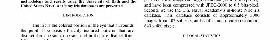

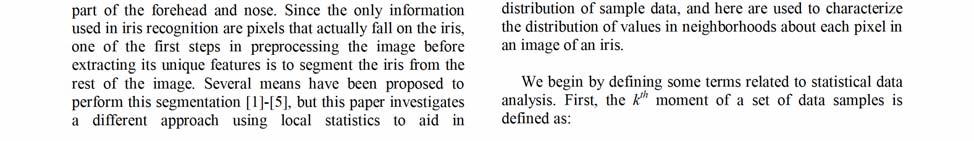

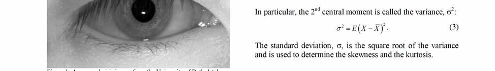
88 86


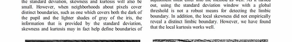
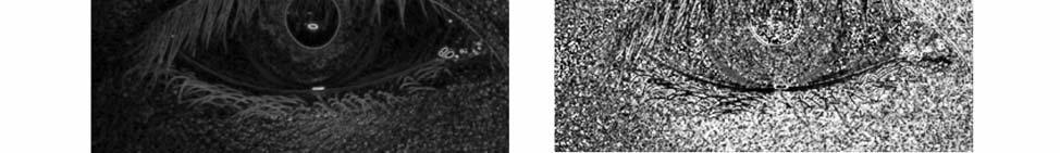
89 87
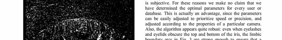
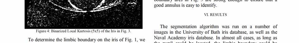

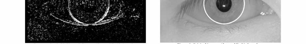
90 88
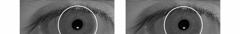
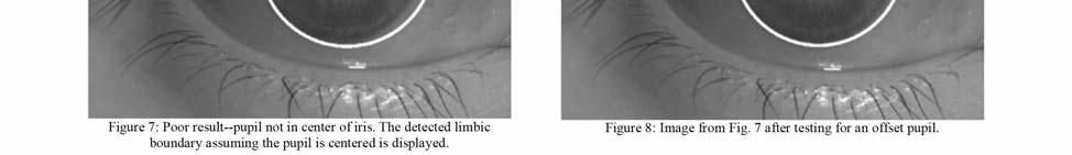
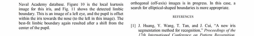
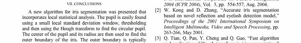
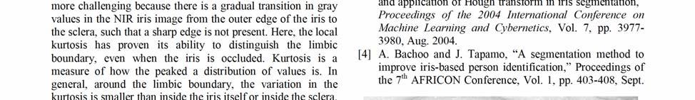
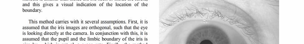

91 89


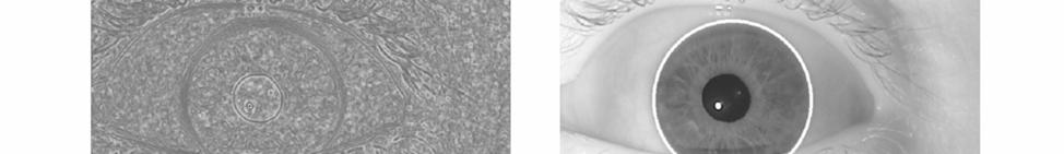
92 90
ANALYSIS OF PARTIAL IRIS RECOGNITION
 ANALYSIS OF PARTIAL IRIS RECOGNITION Yingzi Du, Robert Ives, Bradford Bonney, Delores Etter Electrical Engineering Department, U.S. Naval Academy, Annapolis, MD, USA 21402 ABSTRACT In this paper, we investigate
Iris Recognition using Histogram Analysis
 Iris Recognition using Histogram Analysis Robert W. Ives, Anthony J. Guidry and Delores M. Etter Electrical Engineering Department, U.S. Naval Academy Annapolis, MD 21402-5025 Abstract- Iris recognition
A One-Dimensional Approach for Iris Identification
 A One-Dimensional Approach for Iris Identification Yingzi Du a*, Robert Ives a, Delores Etter a, Thad Welch a, Chein-I Chang b a Electrical Engineering Department, United States Naval Academy, Annapolis,
INTERNATIONAL RESEARCH JOURNAL IN ADVANCED ENGINEERING AND TECHNOLOGY (IRJAET)
") INTERNATIONAL RESEARCH JOURNAL IN ADVANCED ENGINEERING AND TECHNOLOGY (IRJAET) www.irjaet.com ISSN (PRINT) : 2454-4744 ISSN (ONLINE): 2454-4752 Vol. 1, Issue 4, pp.240-245, November, 2015 IRIS RECOGNITION
INTERNATIONAL RESEARCH JOURNAL IN ADVANCED ENGINEERING AND TECHNOLOGY (IRJAET) www.irjaet.com ISSN (PRINT) : 2454-4744 ISSN (ONLINE): 2454-4752 Vol. 1, Issue 4, pp.240-245, November, 2015 IRIS RECOGNITION
Experiments with An Improved Iris Segmentation Algorithm
 Experiments with An Improved Iris Segmentation Algorithm Xiaomei Liu, Kevin W. Bowyer, Patrick J. Flynn Department of Computer Science and Engineering University of Notre Dame Notre Dame, IN 46556, U.S.A.
Iris Segmentation & Recognition in Unconstrained Environment
 www.ijecs.in International Journal Of Engineering And Computer Science ISSN:2319-7242 Volume - 3 Issue -8 August, 2014 Page No. 7514-7518 Iris Segmentation & Recognition in Unconstrained Environment ABSTRACT
A Proficient Matching For Iris Segmentation and Recognition Using Filtering Technique
 A Proficient Matching For Iris Segmentation and Recognition Using Filtering Technique Ms. Priti V. Dable 1, Prof. P.R. Lakhe 2, Mr. S.S. Kemekar 3 Ms. Priti V. Dable 1 (PG Scholar) Comm (Electronics) S.D.C.E.
Iris based Human Identification using Median and Gaussian Filter
 Iris based Human Identification using Median and Gaussian Filter Geetanjali Sharma 1 and Neerav Mehan 2 International Journal of Latest Trends in Engineering and Technology Vol.(7)Issue(3), pp. 456-461
Iris Recognition-based Security System with Canny Filter
 Canny Filter Dr. Computer Engineering Department, University of Technology, Baghdad-Iraq E-mail: hjhh2007@yahoo.com Received: 8/9/2014 Accepted: 21/1/2015 Abstract Image identification plays a great role
Iris Pattern Segmentation using Automatic Segmentation and Window Technique
 Iris Pattern Segmentation using Automatic Segmentation and Window Technique Swati Pandey 1 Department of Electronics and Communication University College of Engineering, Rajasthan Technical University,
IRIS Biometric for Person Identification. By Lakshmi Supriya.D M.Tech 04IT6002 Dept. of Information Technology
 IRIS Biometric for Person Identification By Lakshmi Supriya.D M.Tech 04IT6002 Dept. of Information Technology What are Biometrics? Why are Biometrics used? How Biometrics is today? Iris Iris is the area
Recent research results in iris biometrics
 Recent research results in iris biometrics Karen Hollingsworth, Sarah Baker, Sarah Ring Kevin W. Bowyer, and Patrick J. Flynn Computer Science and Engineering Department, University of Notre Dame, Notre
THE DET CURVE IN ASSESSMENT OF DETECTION TASK PERFORMANCE
 THE DET CURVE IN ASSESSMENT OF DETECTION TASK PERFORMANCE A. Martin*, G. Doddington#, T. Kamm+, M. Ordowski+, M. Przybocki* *National Institute of Standards and Technology, Bldg. 225-Rm. A216, Gaithersburg,
Electro-Optic Identification Research Program: Computer Aided Identification (CAI) and Automatic Target Recognition (ATR)
 and Automatic Target Recognition (ATR)") Electro-Optic Identification Research Program: Computer Aided Identification (CAI) and Automatic Target Recognition (ATR) Phone: (850) 234-4066 Phone: (850) 235-5890 James S. Taylor, Code R22 Coastal Systems
Electro-Optic Identification Research Program: Computer Aided Identification (CAI) and Automatic Target Recognition (ATR) Phone: (850) 234-4066 Phone: (850) 235-5890 James S. Taylor, Code R22 Coastal Systems
International Conference on Innovative Applications in Engineering and Information Technology(ICIAEIT-2017)
") Sparsity Inspired Selection and Recognition of Iris Images 1. Dr K R Badhiti, Assistant Professor, Dept. of Computer Science, Adikavi Nannaya University, Rajahmundry, A.P, India 2. Prof. T. Sudha, Dept.
Sparsity Inspired Selection and Recognition of Iris Images 1. Dr K R Badhiti, Assistant Professor, Dept. of Computer Science, Adikavi Nannaya University, Rajahmundry, A.P, India 2. Prof. T. Sudha, Dept.
Authentication using Iris
 Authentication using Iris C.S.S.Anupama Associate Professor, Dept of E.I.E, V.R.Siddhartha Engineering College, Vijayawada, A.P P.Rajesh Assistant Professor Dept of E.I.E V.R.Siddhartha Engineering College
AN INFRARED IMAGE ACQUISITION AND ANALYSIS METHOD FOR QUANTIFYING OPTICAL RESPONSES TO CHEMICAL AGENT VAPOR EXPOSURE
 AN INFRARED IMAGE ACQUISITION AND ANALYSIS METHOD FOR QUANTIFYING OPTICAL RESPONSES TO CHEMICAL AGENT VAPOR EXPOSURE Dennis B. Miller and Stanley W. Hulet Geo-Centers, Inc. Gunpowder Branch. Aberdeen Proving
Bistatic Underwater Optical Imaging Using AUVs
 Bistatic Underwater Optical Imaging Using AUVs Michael P. Strand Naval Surface Warfare Center Panama City Code HS-12, 110 Vernon Avenue Panama City, FL 32407 phone: (850) 235-5457 fax: (850) 234-4867 email:
Acoustic Change Detection Using Sources of Opportunity
 Acoustic Change Detection Using Sources of Opportunity by Owen R. Wolfe and Geoffrey H. Goldman ARL-TN-0454 September 2011 Approved for public release; distribution unlimited. NOTICES Disclaimers The findings
IRIS Recognition Using Cumulative Sum Based Change Analysis
 IRIS Recognition Using Cumulative Sum Based Change Analysis L.Hari.Hara.Brahma Kuppam Engineering College, Chittoor. Dr. G.N.Kodanda Ramaiah Head of Department, Kuppam Engineering College, Chittoor. Dr.M.N.Giri
Fresnel Lens Characterization for Potential Use in an Unpiloted Atmospheric Vehicle DIAL Receiver System
 NASA/TM-1998-207665 Fresnel Lens Characterization for Potential Use in an Unpiloted Atmospheric Vehicle DIAL Receiver System Shlomo Fastig SAIC, Hampton, Virginia Russell J. DeYoung Langley Research Center,
Biometrics 2/23/17. the last category for authentication methods is. this is the realm of biometrics
 CSC362, Information Security the last category for authentication methods is Something I am or do, which means some physical or behavioral characteristic that uniquely identifies the user and can be used
NOVEL APPROACH OF ACCURATE IRIS LOCALISATION FORM HIGH RESOLUTION EYE IMAGES SUITABLE FOR FAKE IRIS DETECTION
 International Journal of Information Technology and Knowledge Management July-December 2010, Volume 3, No. 2, pp. 685-690 NOVEL APPROACH OF ACCURATE IRIS LOCALISATION FORM HIGH RESOLUTION EYE IMAGES SUITABLE
Improving the Detection of Near Earth Objects for Ground Based Telescopes
 Improving the Detection of Near Earth Objects for Ground Based Telescopes Anthony O'Dell Captain, United States Air Force Air Force Research Laboratories ABSTRACT Congress has mandated the detection of
Feature Extraction Technique Based On Circular Strip for Palmprint Recognition
 Feature Extraction Technique Based On Circular Strip for Palmprint Recognition Dr.S.Valarmathy 1, R.Karthiprakash 2, C.Poonkuzhali 3 1, 2, 3 ECE Department, Bannari Amman Institute of Technology, Sathyamangalam
Drexel Object Occlusion Repository (DOOR) Trip Denton, John Novatnack and Ali Shokoufandeh
 Trip Denton, John Novatnack and Ali Shokoufandeh") Drexel Object Occlusion Repository (DOOR) Trip Denton, John Novatnack and Ali Shokoufandeh Technical Report DU-CS-05-08 Department of Computer Science Drexel University Philadelphia, PA 19104 July, 2005
Drexel Object Occlusion Repository (DOOR) Trip Denton, John Novatnack and Ali Shokoufandeh Technical Report DU-CS-05-08 Department of Computer Science Drexel University Philadelphia, PA 19104 July, 2005
Eye-Gaze Tracking Using Inexpensive Video Cameras. Wajid Ahmed Greg Book Hardik Dave. University of Connecticut, May 2002
 Eye-Gaze Tracking Using Inexpensive Video Cameras Wajid Ahmed Greg Book Hardik Dave University of Connecticut, May 2002 Statement of Problem To track eye movements based on pupil location. The location
Investigation of Modulated Laser Techniques for Improved Underwater Imaging
 Investigation of Modulated Laser Techniques for Improved Underwater Imaging Linda J. Mullen NAVAIR, EO and Special Mission Sensors Division 4.5.6, Building 2185 Suite 1100-A3, 22347 Cedar Point Road Unit
Report Documentation Page
 Svetlana Avramov-Zamurovic 1, Bryan Waltrip 2 and Andrew Koffman 2 1 United States Naval Academy, Weapons and Systems Engineering Department Annapolis, MD 21402, Telephone: 410 293 6124 Email: avramov@usna.edu
ARL-TR-7455 SEP US Army Research Laboratory
 ARL-TR-7455 SEP 2015 US Army Research Laboratory An Analysis of the Far-Field Radiation Pattern of the Ultraviolet Light-Emitting Diode (LED) Engin LZ4-00UA00 Diode with and without Beam Shaping Optics
Fast identification of individuals based on iris characteristics for biometric systems
 Fast identification of individuals based on iris characteristics for biometric systems J.G. Rogeri, M.A. Pontes, A.S. Pereira and N. Marranghello Department of Computer Science and Statistic, IBILCE, Sao
An Efficient Approach for Iris Recognition by Improving Iris Segmentation and Iris Image Compression
 An Efficient Approach for Iris Recognition by Improving Iris Segmentation and Iris Image Compression K. N. Jariwala, SVNIT, Surat, India U. D. Dalal, SVNIT, Surat, India Abstract The biometric person authentication
Real Time Word to Picture Translation for Chinese Restaurant Menus
 Real Time Word to Picture Translation for Chinese Restaurant Menus Michelle Jin, Ling Xiao Wang, Boyang Zhang Email: mzjin12, lx2wang, boyangz @stanford.edu EE268 Project Report, Spring 2014 Abstract--We
Student Independent Research Project : Evaluation of Thermal Voltage Converters Low-Frequency Errors
 . Session 2259 Student Independent Research Project : Evaluation of Thermal Voltage Converters Low-Frequency Errors Svetlana Avramov-Zamurovic and Roger Ashworth United States Naval Academy Weapons and
David Siegel Masters Student University of Cincinnati. IAB 17, May 5 7, 2009 Ford & UM
 Alternator Health Monitoring For Vehicle Applications David Siegel Masters Student University of Cincinnati Report Documentation Page Form Approved OMB No. 0704-0188 Public reporting burden for the collection
Innovative 3D Visualization of Electro-optic Data for MCM
 Innovative 3D Visualization of Electro-optic Data for MCM James C. Luby, Ph.D., Applied Physics Laboratory University of Washington 1013 NE 40 th Street Seattle, Washington 98105-6698 Telephone: 206-543-6854
Sea Surface Backscatter Distortions of Scanning Radar Altimeter Ocean Wave Measurements
 Sea Surface Backscatter Distortions of Scanning Radar Altimeter Ocean Wave Measurements Edward J. Walsh and C. Wayne Wright NASA Goddard Space Flight Center Wallops Flight Facility Wallops Island, VA 23337
Finger print Recognization. By M R Rahul Raj K Muralidhar A Papi Reddy
 Finger print Recognization By M R Rahul Raj K Muralidhar A Papi Reddy Introduction Finger print recognization system is under biometric application used to increase the user security. Generally the biometric
Global and Local Quality Measures for NIR Iris Video
 Global and Local Quality Measures for NIR Iris Video Jinyu Zuo and Natalia A. Schmid Lane Department of Computer Science and Electrical Engineering West Virginia University, Morgantown, WV 26506 jzuo@mix.wvu.edu
Feature Extraction Techniques for Dorsal Hand Vein Pattern
 Feature Extraction Techniques for Dorsal Hand Vein Pattern Pooja Ramsoful, Maleika Heenaye-Mamode Khan Department of Computer Science and Engineering University of Mauritius Mauritius pooja.ramsoful@umail.uom.ac.mu,
Improving the Safety and Efficiency of Roadway Maintenance Phase II: Developing a Vision Guidance System for the Robotic Roadway Message Painter
 Improving the Safety and Efficiency of Roadway Maintenance Phase II: Developing a Vision Guidance System for the Robotic Roadway Message Painter Final Report Prepared by: Ryan G. Rosandich Department of
Iris Recognition using Hamming Distance and Fragile Bit Distance
 IJSRD - International Journal for Scientific Research & Development Vol. 3, Issue 06, 2015 ISSN (online): 2321-0613 Iris Recognition using Hamming Distance and Fragile Bit Distance Mr. Vivek B. Mandlik
ECEN 4606, UNDERGRADUATE OPTICS LAB
 ECEN 4606, UNDERGRADUATE OPTICS LAB Lab 2: Imaging 1 the Telescope Original Version: Prof. McLeod SUMMARY: In this lab you will become familiar with the use of one or more lenses to create images of distant
Performance Factors. Technical Assistance. Fundamental Optics
 Performance Factors After paraxial formulas have been used to select values for component focal length(s) and diameter(s), the final step is to select actual lenses. As in any engineering problem, this
Modeling an HF NVIS Towel-Bar Antenna on a Coast Guard Patrol Boat A Comparison of WIPL-D and the Numerical Electromagnetics Code (NEC)
") Modeling an HF NVIS Towel-Bar Antenna on a Coast Guard Patrol Boat A Comparison of WIPL-D and the Numerical Electromagnetics Code (NEC) Darla Mora, Christopher Weiser and Michael McKaughan United States
Modeling an HF NVIS Towel-Bar Antenna on a Coast Guard Patrol Boat A Comparison of WIPL-D and the Numerical Electromagnetics Code (NEC) Darla Mora, Christopher Weiser and Michael McKaughan United States
Vein and Fingerprint Identification Multi Biometric System: A Novel Approach
 Vein and Fingerprint Identification Multi Biometric System: A Novel Approach Hatim A. Aboalsamh Abstract In this paper, a compact system that consists of a Biometrics technology CMOS fingerprint sensor
AUVFEST 05 Quick Look Report of NPS Activities
 AUVFEST 5 Quick Look Report of NPS Activities Center for AUV Research Naval Postgraduate School Monterey, CA 93943 INTRODUCTION Healey, A. J., Horner, D. P., Kragelund, S., Wring, B., During the period
Radar Detection of Marine Mammals
 DISTRIBUTION STATEMENT A. Approved for public release; distribution is unlimited. Radar Detection of Marine Mammals Charles P. Forsyth Areté Associates 1550 Crystal Drive, Suite 703 Arlington, VA 22202
Modeling and Evaluation of Bi-Static Tracking In Very Shallow Water
 Modeling and Evaluation of Bi-Static Tracking In Very Shallow Water Stewart A.L. Glegg Dept. of Ocean Engineering Florida Atlantic University Boca Raton, FL 33431 Tel: (954) 924 7241 Fax: (954) 924-7270
Published by: PIONEER RESEARCH & DEVELOPMENT GROUP (www.prdg.org) 1
 1") IJREAT International Journal of Research in Engineering & Advanced Technology, Volume 2, Issue 2, Apr- Generating an Iris Code Using Iris Recognition for Biometric Application S.Banurekha 1, V.Manisha
IJREAT International Journal of Research in Engineering & Advanced Technology, Volume 2, Issue 2, Apr- Generating an Iris Code Using Iris Recognition for Biometric Application S.Banurekha 1, V.Manisha
Proposed Method for Off-line Signature Recognition and Verification using Neural Network
 e-issn: 2349-9745 p-issn: 2393-8161 Scientific Journal Impact Factor (SJIF): 1.711 International Journal of Modern Trends in Engineering and Research www.ijmter.com Proposed Method for Off-line Signature
Automatic Iris Segmentation Using Active Near Infra Red Lighting
 Automatic Iris Segmentation Using Active Near Infra Red Lighting Carlos H. Morimoto Thiago T. Santos Adriano S. Muniz Departamento de Ciência da Computação - IME/USP Rua do Matão, 1010, São Paulo, SP,
About user acceptance in hand, face and signature biometric systems
 About user acceptance in hand, face and signature biometric systems Aythami Morales, Miguel A. Ferrer, Carlos M. Travieso, Jesús B. Alonso Instituto Universitario para el Desarrollo Tecnológico y la Innovación
Texture characterization in DIRSIG
 Rochester Institute of Technology RIT Scholar Works Theses Thesis/Dissertation Collections 2001 Texture characterization in DIRSIG Christy Burtner Follow this and additional works at: http://scholarworks.rit.edu/theses
Contents Technical background II. RUMBA technical specifications III. Hardware connection IV. Set-up of the instrument Laboratory set-up
 RUMBA User Manual Contents I. Technical background... 3 II. RUMBA technical specifications... 3 III. Hardware connection... 3 IV. Set-up of the instrument... 4 1. Laboratory set-up... 4 2. In-vivo set-up...
Biometrics Final Project Report
 Andres Uribe au2158 Introduction Biometrics Final Project Report Coin Counter The main objective for the project was to build a program that could count the coins money value in a picture. The work was
MONITORING RUBBLE-MOUND COASTAL STRUCTURES WITH PHOTOGRAMMETRY
 ,. CETN-III-21 2/84 MONITORING RUBBLE-MOUND COASTAL STRUCTURES WITH PHOTOGRAMMETRY INTRODUCTION: Monitoring coastal projects usually involves repeated surveys of coastal structures and/or beach profiles.
ZKTECO COLLEGE- FUNDAMENTAL OF FINGER VEIN RECOGNITION
 ZKTECO COLLEGE- FUNDAMENTAL OF FINGER VEIN RECOGNITION What are Finger Veins? Veins are blood vessels which present throughout the body as tubes that carry blood back to the heart. As its name implies,
A New Scheme for Acoustical Tomography of the Ocean
 A New Scheme for Acoustical Tomography of the Ocean Alexander G. Voronovich NOAA/ERL/ETL, R/E/ET1 325 Broadway Boulder, CO 80303 phone (303)-497-6464 fax (303)-497-3577 email agv@etl.noaa.gov E.C. Shang
Research on Pupil Segmentation and Localization in Micro Operation Hu BinLiang1, a, Chen GuoLiang2, b, Ma Hui2, c
 3rd International Conference on Machinery, Materials and Information Technology Applications (ICMMITA 2015) Research on Pupil Segmentation and Localization in Micro Operation Hu BinLiang1, a, Chen GuoLiang2,
Final Report to. Air Force Office of Scientific Research Aerospace and Materials Science Structural Mechanics. Grant No.
 0 7 FEB 2000 Final Report to Air Force Office of Scientific Research Aerospace and Materials Science Structural Mechanics Grant No. F49620-98-1-0236 AN ELECTRONIC SPECKLE PATTERN INTERFEROMETRY SYSTEM
APPLICATION OF COMPUTER VISION FOR DETERMINATION OF SYMMETRICAL OBJECT POSITION IN THREE DIMENSIONAL SPACE
 APPLICATION OF COMPUTER VISION FOR DETERMINATION OF SYMMETRICAL OBJECT POSITION IN THREE DIMENSIONAL SPACE Najirah Umar 1 1 Jurusan Teknik Informatika, STMIK Handayani Makassar Email : najirah_stmikh@yahoo.com
Lattice Spacing Effect on Scan Loss for Bat-Wing Phased Array Antennas
 Lattice Spacing Effect on Scan Loss for Bat-Wing Phased Array Antennas I. Introduction Thinh Q. Ho*, Charles A. Hewett, Lilton N. Hunt SSCSD 2825, San Diego, CA 92152 Thomas G. Ready NAVSEA PMS500, Washington,
Coherent distributed radar for highresolution
 . Calhoun Drive, Suite Rockville, Maryland, 8 () 9 http://www.i-a-i.com Intelligent Automation Incorporated Coherent distributed radar for highresolution through-wall imaging Progress Report Contract No.
ABSTRACT I. INTRODUCTION II. LITERATURE SURVEY
 International Journal of Scientific Research in Computer Science, Engineering and Information Technology 2017 IJSRCSEIT Volume 2 Issue 3 ISSN : 2456-3307 IRIS Biometric Recognition for Person Identification
Buttress Thread Machining Technical Report Summary Final Report Raytheon Missile Systems Company NCDMM Project # NP MAY 12, 2006
 Improved Buttress Thread Machining for the Excalibur and Extended Range Guided Munitions Raytheon Tucson, AZ Effective Date of Contract: September 2005 Expiration Date of Contract: April 2006 Buttress
Note on CASIA-IrisV3
 Note on CASIA-IrisV3 1. Introduction With fast development of iris image acquisition technology, iris recognition is expected to become a fundamental component of modern society, with wide application
MINIATURIZED ANTENNAS FOR COMPACT SOLDIER COMBAT SYSTEMS
 MINIATURIZED ANTENNAS FOR COMPACT SOLDIER COMBAT SYSTEMS Iftekhar O. Mirza 1*, Shouyuan Shi 1, Christian Fazi 2, Joseph N. Mait 2, and Dennis W. Prather 1 1 Department of Electrical and Computer Engineering
SECTION I - CHAPTER 2 DIGITAL IMAGING PROCESSING CONCEPTS
 RADT 3463 - COMPUTERIZED IMAGING Section I: Chapter 2 RADT 3463 Computerized Imaging 1 SECTION I - CHAPTER 2 DIGITAL IMAGING PROCESSING CONCEPTS RADT 3463 COMPUTERIZED IMAGING Section I: Chapter 2 RADT
Army Acoustics Needs
 Army Acoustics Needs DARPA Air-Coupled Acoustic Micro Sensors Workshop by Nino Srour Aug 25, 1999 US Attn: AMSRL-SE-SA 2800 Powder Mill Road Adelphi, MD 20783-1197 Tel: (301) 394-2623 Email: nsrour@arl.mil
Hybrid QR Factorization Algorithm for High Performance Computing Architectures. Peter Vouras Naval Research Laboratory Radar Division
 Hybrid QR Factorization Algorithm for High Performance Computing Architectures Peter Vouras Naval Research Laboratory Radar Division 8/1/21 Professor G.G.L. Meyer Johns Hopkins University Parallel Computing
Marine~4 Pbscl~ PHYS(O laboratory -Ip ISUt
 Marine~4 Pbscl~ PHYS(O laboratory -Ip ISUt il U!d U Y:of thc SCrip 1 nsti0tio of Occaiiographv U n1icrsi ry of' alifi ra, San Die".(o W.A. Kuperman and W.S. Hodgkiss La Jolla, CA 92093-0701 17 September
Automatic License Plate Recognition System using Histogram Graph Algorithm
 Automatic License Plate Recognition System using Histogram Graph Algorithm Divyang Goswami 1, M.Tech Electronics & Communication Engineering Department Marudhar Engineering College, Raisar Bikaner, Rajasthan,
Noise Tolerance of Improved Max-min Scanning Method for Phase Determination
 Noise Tolerance of Improved Max-min Scanning Method for Phase Determination Xu Ding Research Assistant Mechanical Engineering Dept., Michigan State University, East Lansing, MI, 48824, USA Gary L. Cloud,
ROBOT VISION. Dr.M.Madhavi, MED, MVSREC
 ROBOT VISION Dr.M.Madhavi, MED, MVSREC Robotic vision may be defined as the process of acquiring and extracting information from images of 3-D world. Robotic vision is primarily targeted at manipulation
Software Development Kit to Verify Quality Iris Images
 Software Development Kit to Verify Quality Iris Images Isaac Mateos, Gualberto Aguilar, Gina Gallegos Sección de Estudios de Posgrado e Investigación Culhuacan, Instituto Politécnico Nacional, México D.F.,
2008 Monitoring Research Review: Ground-Based Nuclear Explosion Monitoring Technologies INFRAMONITOR: A TOOL FOR REGIONAL INFRASOUND MONITORING
 INFRAMONITOR: A TOOL FOR REGIONAL INFRASOUND MONITORING Stephen J. Arrowsmith and Rod Whitaker Los Alamos National Laboratory Sponsored by National Nuclear Security Administration Contract No. DE-AC52-06NA25396
Created by Neevia Personal Converter trial version
 U.S.N.A. --- Trident Scholar project report; no. 329 (2005) Direction of Arrival Estimation Using a Reconfigurable Array by Midshipman 1/c Danica L. Adams, Class of 2005 United States Naval Academy Annapolis,
Adaptive CFAR Performance Prediction in an Uncertain Environment
 Adaptive CFAR Performance Prediction in an Uncertain Environment Jeffrey Krolik Department of Electrical and Computer Engineering Duke University Durham, NC 27708 phone: (99) 660-5274 fax: (99) 660-5293
REPORT DOCUMENTATION PAGE. A peer-to-peer non-line-of-sight localization system scheme in GPS-denied scenarios. Dr.
 REPORT DOCUMENTATION PAGE Form Approved OMB No. 0704-0188 The public reporting burden for this collection of information is estimated to average 1 hour per response, including the time for reviewing instructions,
The Best Bits in an Iris Code
 IEEE Transactions on Pattern Analysis and Machine Intelligence (PAMI), to appear. 1 The Best Bits in an Iris Code Karen P. Hollingsworth, Kevin W. Bowyer, Fellow, IEEE, and Patrick J. Flynn, Senior Member,
REPORT DOCUMENTATION PAGE
 REPORT DOCUMENTATION PAGE Form Approved OMB NO. 0704-0188 The public reporting burden for this collection of information is estimated to average 1 hour per response, including the time for reviewing instructions,
Non-Data Aided Doppler Shift Estimation for Underwater Acoustic Communication
 Non-Data Aided Doppler Shift Estimation for Underwater Acoustic Communication (Invited paper) Paul Cotae (Corresponding author) 1,*, Suresh Regmi 1, Ira S. Moskowitz 2 1 University of the District of Columbia,
THE NATIONAL SHIPBUILDING RESEARCH PROGRAM
 SHIP PRODUCTION COMMITTEE FACILITIES AND ENVIRONMENTAL EFFECTS SURFACE PREPARATION AND COATINGS DESIGN/PRODUCTION INTEGRATION HUMAN RESOURCE INNOVATION MARINE INDUSTRY STANDARDS WELDING INDUSTRIAL ENGINEERING
Simulation Comparisons of Three Different Meander Line Dipoles
 Simulation Comparisons of Three Different Meander Line Dipoles by Seth A McCormick ARL-TN-0656 January 2015 Approved for public release; distribution unlimited. NOTICES Disclaimers The findings in this
Image Averaging for Improved Iris Recognition
 Image Averaging for Improved Iris Recognition Karen P. Hollingsworth, Kevin W. Bowyer, and Patrick J. Flynn University of Notre Dame Abstract. We take advantage of the temporal continuity in an iris video
CHAPTER 4 LOCATING THE CENTER OF THE OPTIC DISC AND MACULA
 90 CHAPTER 4 LOCATING THE CENTER OF THE OPTIC DISC AND MACULA The objective in this chapter is to locate the centre and boundary of OD and macula in retinal images. In Diabetic Retinopathy, location of
Overview. Pinhole camera model Projective geometry Vanishing points and lines Projection matrix Cameras with Lenses Color Digital image
 Camera & Color Overview Pinhole camera model Projective geometry Vanishing points and lines Projection matrix Cameras with Lenses Color Digital image Book: Hartley 6.1, Szeliski 2.1.5, 2.2, 2.3 The trip
INDIAN VEHICLE LICENSE PLATE EXTRACTION AND SEGMENTATION
 International Journal of Computer Science and Communication Vol. 2, No. 2, July-December 2011, pp. 593-599 INDIAN VEHICLE LICENSE PLATE EXTRACTION AND SEGMENTATION Chetan Sharma 1 and Amandeep Kaur 2 1
PRACTICAL IMAGE AND VIDEO PROCESSING USING MATLAB
 PRACTICAL IMAGE AND VIDEO PROCESSING USING MATLAB OGE MARQUES Florida Atlantic University *IEEE IEEE PRESS WWILEY A JOHN WILEY & SONS, INC., PUBLICATION CONTENTS LIST OF FIGURES LIST OF TABLES FOREWORD
Biometric Recognition Techniques
 Biometric Recognition Techniques Anjana Doshi 1, Manisha Nirgude 2 ME Student, Computer Science and Engineering, Walchand Institute of Technology Solapur, India 1 Asst. Professor, Information Technology,
Leaving Certificate 201
 Coimisiún na Scrúduithe Stáit State Examinations Commission Leaving Certificate 201 Marking Scheme Design and Communication Graphics Ordinary Level Note to teachers and students on the use of published
Evanescent Acoustic Wave Scattering by Targets and Diffraction by Ripples
 Evanescent Acoustic Wave Scattering by Targets and Diffraction by Ripples PI name: Philip L. Marston Physics Department, Washington State University, Pullman, WA 99164-2814 Phone: (509) 335-5343 Fax: (509)
Frequency Stabilization Using Matched Fabry-Perots as References
 April 1991 LIDS-P-2032 Frequency Stabilization Using Matched s as References Peter C. Li and Pierre A. Humblet Massachusetts Institute of Technology Laboratory for Information and Decision Systems Cambridge,
ISSN: [Deepa* et al., 6(2): February, 2017] Impact Factor: 4.116
![ISSN: [Deepa* et al., 6(2): February, 2017] Impact Factor: 4.116](/thumbs/82/86939300.jpg "ISSN: [Deepa* et al., 6(2): February, 2017] Impact Factor: 4.116") IJESRT INTERNATIONAL JOURNAL OF ENGINEERING SCIENCES & RESEARCH TECHNOLOGY IRIS RECOGNITION BASED ON IRIS CRYPTS Asst.Prof. N.Deepa*, V.Priyanka student, J.Pradeepa student. B.E CSE,G.K.M college of engineering
IJESRT INTERNATIONAL JOURNAL OF ENGINEERING SCIENCES & RESEARCH TECHNOLOGY IRIS RECOGNITION BASED ON IRIS CRYPTS Asst.Prof. N.Deepa*, V.Priyanka student, J.Pradeepa student. B.E CSE,G.K.M college of engineering
A Study of Slanted-Edge MTF Stability and Repeatability
 A Study of Slanted-Edge MTF Stability and Repeatability Jackson K.M. Roland Imatest LLC, 2995 Wilderness Place Suite 103, Boulder, CO, USA ABSTRACT The slanted-edge method of measuring the spatial frequency
IRIS RECOGNITION USING GABOR
 IRIS RECOGNITION USING GABOR Shirke Swati D.. Prof.Gupta Deepak ME-COMPUTER-I Assistant Prof. ME COMPUTER CAYMT s Siddhant COE, CAYMT s Siddhant COE Sudumbare,Pune Sudumbare,Pune Abstract The iris recognition
Thermal Simulation of Switching Pulses in an Insulated Gate Bipolar Transistor (IGBT) Power Module
 Power Module") Thermal Simulation of Switching Pulses in an Insulated Gate Bipolar Transistor (IGBT) Power Module by Gregory K Ovrebo ARL-TR-7210 February 2015 Approved for public release; distribution unlimited. NOTICES
Thermal Simulation of Switching Pulses in an Insulated Gate Bipolar Transistor (IGBT) Power Module by Gregory K Ovrebo ARL-TR-7210 February 2015 Approved for public release; distribution unlimited. NOTICES
Robotics and Artificial Intelligence. Rodney Brooks Director, MIT Computer Science and Artificial Intelligence Laboratory CTO, irobot Corp
 Robotics and Artificial Intelligence Rodney Brooks Director, MIT Computer Science and Artificial Intelligence Laboratory CTO, irobot Corp Report Documentation Page Form Approved OMB No. 0704-0188 Public
Coastal Benthic Optical Properties Fluorescence Imaging Laser Line Scan Sensor
 Coastal Benthic Optical Properties Fluorescence Imaging Laser Line Scan Sensor Dr. Michael P. Strand Naval Surface Warfare Center Coastal Systems Station, Code R22 6703 West Highway 98, Panama City, FL