Air Sync Air Remote User s Guide EN
|
|
|
- Eunice Lambert
- 6 years ago
- Views:
Transcription
1 Air Sync Air Remote User s Guide EN This user guide is available in other languages at profoto.com/support CN 其他语言版本的用户指南可从 profoto.com/cn/support 下载 DE Das Bedienungs-Handbuch is auch in anderen Sprachen verfügbar unter profoto.com/de/support ES Esta guía de usuario está disponible en otros idiomas en profoto.com/support FR Ce manuel d utilisation est également disponible en d autres langues sur profoto.com/fr/support IT Questa guida per gli utenti è disponibile in altre lingue su profoto.com/it/support JP このユーザーガイドは profoto.com/ja/support に他の言語でもご用意しています RU Инструкция пользователя на других языках доступна на profoto.com/ru/support
2 2
3 Thank you for choosing Profoto Air Remote Air Sync Thanks for showing us your confidence by investing in a Profoto Air device. For more than four decades we have sought the perfect light. What pushes us is our conviction that we can offer even yet better tools for the most demanding photographers. Before our products are shipped we have them pass an extensive and strict testing program. We check that each individual product comply with specified performance, quality and safety. For this reason our flash equipment is widely used in rental studios and rental houses worldwide, from Paris, London, Milan, New York, Tokyo to Cape Town. 3 Professional photographers around the world have come to value Profoto s expertise in lighting and light-shaping. Our extensive range of Light Shaping Tools offers photographers unlimited possibilities for creating and adjusting their own light. Every single reflector and accessory creates its special light and the unique Profoto focusing system offers you the possibility to create your own light with only a few different reflectors. Enjoy your Profoto product!
4 4 Safety instructions SAFETY PRECAUTIONS! Do not operate the equipment before studying the instruction manual and the accompanying safety. Make sure that Profoto Safety Instructions is always accompanied the equipment! Profoto products are intended for professional use! Generator, lamp heads and accessories are only intended for indoor photographic use. Do not place or use the equipment where it can be exposed to moisture, extreme electromagnetic fields or in areas with flammable gases or dust! Do not expose the equipment to dripping or splashing. Do not place any objects filled with liquids, such as vases, on or near the equipment. Do not expose the equipment to hasty temperature changes in humid conditions as this could lead to condensation water in the unit. Do not connect this equipment to flash equipment from other brands. Do not use flash heads without supplied protective glass covers or protective grids. Glass covers shall be changed if it has become visibly damaged to such an extent that their effectiveness is impaired, for example by cracks or deep scratches. Lamps shall be changed if they are damaged or thermally deformed. When placing a lamp into the holder ensure not to touch the bulb with bare hands. Equipment must only be serviced, modified or repaired by authorized and competent service personnel! Warning - The terminals marked with the flash symbol are hazardous live. WARNING Electrical Shock High Voltage! Mains powered generator shall always be connected to a mains socket outlet with a protective earthing connection! Only use Profoto extension cables! Do not open or disassemble generator or lamp head! Equipment operates with high voltage. Generator capacitors are electrically charged for a considerable time after being turned off. Do not touch modeling lamp or flash tube when mounting umbrella metal shaft in its reflector hole. Disconnect lamp head cable between generator and lamp head when changing modeling lamp or flash tube! The mains plug or appliance coupler is used as disconnect device. The disconnect device shall remain readily operable. Batteries (battery pack or batteries installed) shall not be exposed to excessive heat such as sunshine, fire or the like. Caution Burn Hazard Hot Parts! Do not touch hot parts with bare fingers! Modeling lamps, flash tubes and certain metal parts emit strong heat when used! Do not point modeling lamps or flash tubes too close to persons. All lamps may on rare occasions explode and throw out hot particles! Make sure that rated voltage for modeling lamp corresponds with technical data of user guide regarding power supply! NOTICE Equipment Overheating Risk Remove transport cap from lamp head before use! Do not obstruct ventilation by placing filters, diffusing materials, etc. over inlets and outlets of the equipment ventilation or directly over glass cover, modeling lamp or flash tube! Note about RF! This equipment makes use of the radio spectrum and emits radio frequency energy. Proper care should be taken when the device is integrated in systems. Make sure that all specifications within this document are followed, especially those concerning operating temperature and supply voltage range. Make sure the device is operated according to local regulations. The frequency spectrum this device is using is shared with other users. Interference can not be ruled out. Final Disposal Equipment contains electrical and electronic components that could be harmful to the environment. Equipment may be returned to Profoto distributors free of charge for recycling according to WEEE. Follow local legal requirements for separate disposal of waste, for instance WEEE directive for electrical and electronic equipment on the European market, when product life has ended!

 Profoto Air")

5 Package contents Air Remote Air Sync 5 Profoto Air Sync ( ) Profoto Air Remote ( ) Profoto Air Sync Kit ( )
6 6
7 Table of Contents System description...8 Profoto Air products...8 Profoto Air Remote...8 Profoto Air Sync...8 Profoto Air USB...8 Profoto Studio Air...8 Nomenclature...9 Applications...10 Remote control...10 Remote camera release...10 Relay...11 Functions...12 Transmit/Receive mode selection...12 Channel selection...12 Group selection...12 Remote control...12 Master mode...13 Command confirmation...13 Test function...13 Fast mode...13 Auto Power Off...13 Connections...13 Batteries...14 Operating instructions...15 Remote flash Synchronization...15 Release of remote camera...18 Relay...21 Additional functions...23 Technical data...24 Profoto Air Remote...24 Regulatory Information...25 World-wide Usage of Radio Spectrum...25 EU Declaration of Conformity...26 Unites States and Canada...27 F.C.C. and Industry Canada...27 Japan...28 Air Remote Air Sync 7
8 System description Profoto Air is a wireless system for convenient remote control of both your camera and your flash equipment. The small and lightweight Profoto Air device gives you full freedom of movement, allowing you to concentrate on the creative side of your work. The Profoto Air system is operating on one of eight selectable radio channels on the 2.4 GHz radio frequency band, for world wide use. 8 Profoto Air products All Profoto flash generators with Profoto Air inside can be controlled via the Profoto Air system. Profoto Air Remote The Profoto Air Remote offers complete generator control at your camera or in your hand, including flash energy and modeling light control. The device controls practically an infinite number of generators in up to six groups, either all at once in Master mode, or in individual groups. Profoto Air Remote also allows remote camera release and flash synchronization. Profoto Air Sync Profoto Air Sync allows remote camera release and flash synchronization of practically an infinite number of generators, with the same high performance as Profoto Air Remote. Profoto Air USB The Profoto Air USB device is a USB 2.0 transceiver, which connects your flash generators with integrated Profoto Air functionality to your PC or Mac via a wireless connection. Profoto Air USB allows control of your light from as far away as 300 m/1000 ft (free line of sight). Profoto Studio Air Profoto Studio Air is a software solution for both PC and Mac, which gives you full control of all your generators and lamp heads from your computer. You can control each lamp head individually or group them to control multiple heads or packs at one time. You can save customer lighting setups for use at a later time. Profoto Air symbol
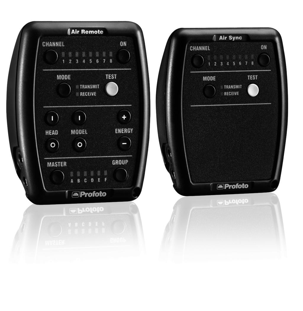
9 Nomenclature Profoto Air Remote Channel Indicators 2. Channel Button 3. Transmit Indicator 4. Mode Button 5. On Button 6. Test Button 7. Receive Indicator 8. Model Button I 9. Head Button I 10. Head Button Model Button Master Button 13. Energy Button Energy Button 15. Group Button 16. Group Indicators 17. In Connector 18. Out Connector 19. Hot Shoe Connector Air Remote Air Sync Profoto Air Sync Connections
10 Applications Synchronization Both the Profoto Air Sync and Profoto Air Remote devices can be used to remotely synchronize flash generators. All Profoto Air generators that have the same radio channel set will be synchronized simultaneously. For generators that do not have a built-in Profoto Air receiver, a Profoto Air device can be connected and used as receiver. 10 Remote control Profoto Air Remote can be used for remote control of generators with built-in Profoto Air functionality. Instead of pressing buttons and turning controls on the generator, settings and functions can be adjusted from the Profoto Air Remote device. It is possible to remotely control the power settings of lamp heads, turn the lamp heads on/off and turn the modeling light on/ off. Changes made with Profoto Air Remote take immediate effect on the generator. By the use of groups, selected lamp heads on one or several generators can be controlled simultaneously with Profoto Air Remote. Group selection allows a large light bank with several lamp heads, for example the background light, to be controlled as one light source. Remote camera release Both Profoto Air Sync and Profoto Air Remote devices can be used to remotely release a camera. For wireless remote release, one Profoto Air device, acting as receiver, is connected to the camera and another Profoto Air device is used as transmitter of the release signal.
11 Relay Both Profoto Air Sync and Profoto Air Remote devices can be used to remotely release a camera and automatically flash the generator(s) in sync with the camera. Two Profoto Air devices are connected to the camera, one acting as receiver of the release signal from the handheld Profoto Air device and the other acting as transmitter of the sync signal to the generator. Different radio channels are used for the release and sync signaling. Air Remote Air Sync 11
12 12 Functions Transmit/Receive mode selection The Mode Button [4] is used to set the Profoto Air device to transmitter or receiver. The Transmit Indicator [3] and the Receive Indicator [7] indicates the selected mode. Channel selection Channel selection is used to select one of eight specific frequencies in the 2.4 GHz band. The frequencies are evenly spread over the entire frequency band, to optimize reliable functionality. The large number of radio channels makes it possible to select a channel that is not interfered by other photographers using Profoto Air, or by WLAN and Bluetooth devices and other radio equipment operating on the same widely used 2.4 GHz frequency band. For synchronization and/or remote control of one or several generators, the same radio channel shall be set on all generators and on the Profoto Air device(s). For remote camera release, the same channel shall be set on both Profoto Air devices (transmitter and receiver.) Channel selection on the Profoto Air Sync and Profoto Air Remote devices is made with the Channel Button [2]. The Channel Indicator [1] corresponding to the selected radio channel (1-8) is illuminated. Group selection Groups are used to allow remote radio control of selected generator lamp heads. All lamp heads that are assigned to the same group will be controlled simultaneously. The lamp heads on a generator can be assigned to different groups. Lamp heads on different generators can be assigned to the same group. Group selection on the Profoto Air Remote device is made with the Group Button [15]. The Group Indicator [16] corresponding to the selected radio group (A-F) is illuminated. The Master Button [12] is used to select all groups. Remote control Remote radio control is available for generators with built-in Profoto Air functionality. For remote radio control, both the Channel and Group settings on the Profoto Air Remote device must match the Channel and Group settings of the lamp heads in the group. The Head Button 1 [9] is used to turn on the flash lamp heads. The Head Button 0 [10] is used to turn off the flash lamp heads. The Model Button 1 [8] is used to turn on the modeling light. The Model Button 0 [11] is used to turn off the modeling light. The Energy Button + [13] is used to increase the energy level. The Energy Button - [14] is used to decrease the energy level.
13 Press the Energy Button < 2 seconds to adjust the energy level in 1/10 f-stop increments. Press the Energy Button > 2 seconds to adjust the energy level in 1 f-stop increments. If the energy level of any flash lamp head in the group is in minimum or maximum position, all energy levels will remain unchanged; see section Command confirmation below. Master mode In Master mode, the same remote control command is sent to all Groups on the selected Channel. With the Master Button [12] on the Profoto Air Remote device, all Groups are selected and will be affected by the remote control commands. Command confirmation If an energy level cannot be set by the generator as commanded, because the energy of a lamp head is set to minimum or maximum level, the Profoto Air Remote device will make an acoustic sound to signal that the command was not executed. The energy level of all flash lamp heads in the group will remain unchanged. Air Remote Air Sync 13 Test function The Test Button [6] is used to manually transmit a sync signal, verifying expected functionality, for remote camera release or flash triggering. The Test Button [6] is also used to transmit the release signal, for remote camera release. If the camera is set up in single mode, there will be one single shot when the Test Button [6] is pressed. If the camera is set up for continuous mode, the camera will continue shooting as long as the Test Button [6] is held down. Because of a lag effect, the camera might take a few more shots after the Test Button [6] has been released. Fast mode The Profoto Air Sync and Profoto Air Remote devices deliver sync signals with a very short delay. In Fast mode, the delay is even shorter. Fast mode is only recommended when working with very short camera shutter times, as the battery consumption is considerably higher. In Fast mode, the remote control functionality (available in Profoto Air Remote) is disabled and inoperative. For more information, see last section on Additional functions. Auto Power Off The Profoto Air device is automatically turned off after 30 minutes of inactivity. The Auto Power Off function is possible to disable. For more information, see last section on Additional functions. Connections When the Profoto Air Sync or Profoto Air Remote device is used as a transmitter to remotely synchronize flash generators and speedlights, the device shall be connected to the camera via the Hot Shoe Connector [19] or via a cable connected to the In Connector [17].
14 When the Profoto Air device is used as a receiver for remote flash synchronization, the device shall be connected to the generator s sync input socket or to the speedlight s PC terminal via a cable connected to the Out Connector [18]. For remote camera release in single mode, the Profoto Air Sync or Profoto Air Remote device shall be connected to the camera via a cable connected to the Out Connector [18]. For remote camera release in continuous mode, the Profoto Air Sync or Profoto Air Remote device shall be connected to the camera via a cable connected to the In Connector [17]. 14 Batteries The Profoto Air Sync and Profoto Air Remote devices are powered by two standard AAA batteries.
 Slide the Hot Shoe Connector [19] on the Profoto Air device into")
![the camera s hot shoe. b) Connect a sync cable from the camera to the In Connector [16] on the Profoto Air device. Generator setup (without built-in Profoto Air) 1.](/docs-images/75/71952443/images/15-1.jpg "Connect the Profoto Air device to the generator, via a cable from the Out Connector [18] on the device to the sync input socket on the generator or the PC terminal on the speedlight. 2.")
![Press and hold down the On Button [5] to turn on the Profoto Air device. 3. Press the Channel Button [2] until the desired Channel Indicator [1] is illuminated.](/docs-images/75/71952443/images/15-2.jpg "The selected channel shall be the same for all generators. 4. Press the Mode Button [4] and verify that the Receive Indicator [7] is illuminated. 5.")
15 Operating instructions Remote flash Synchronization Profoto Air devices can be used to remotely synchronize flash generators and various speedlights equipped with a PC terminal. Camera setup Connect the Profoto Air device to the camera, using one of the following methods: Air Remote Air Sync 15 a) Slide the Hot Shoe Connector [19] on the Profoto Air device into the camera s hot shoe. b) Connect a sync cable from the camera to the In Connector [16] on the Profoto Air device. Generator setup (without built-in Profoto Air) 1. Connect the Profoto Air device to the generator, via a cable from the Out Connector [18] on the device to the sync input socket on the generator or the PC terminal on the speedlight. 2. Press and hold down the On Button [5] to turn on the Profoto Air device. 3. Press the Channel Button [2] until the desired Channel Indicator [1] is illuminated. The selected channel shall be the same for all generators. 4. Press the Mode Button [4] and verify that the Receive Indicator [7] is illuminated. 5. For proper setup when using a speedlight, consult the user manual of the actual speedlight.

16 16 Generator setup (with built-in Profoto Air) 1. Set the generator to synchronization via radio. 2. Select the same radio channel on all generators. Synchronization 1. Press and hold down the On Button [5] to turn on the Profoto Air device on the camera. 2. Verify that the Transmit Indicator [3] is illuminated. 3. Press the Channel Button [2] until the desired Channel Indicator [1] is illuminated. The selected channel shall be the same as the radio channel setting on the generators and/or speedlights. 4. Press the Test Button [6] to verify that the generators and/or speedlights flash as expected. Remote generator control Generators with built-in Profoto Air functionality can be remotely controlled with a Profoto Air Remote device Generator setup 1. Set the generator to synchronization via radio. 2. Select the same radio channel on all generators. 3. Select the same group settings for all lamp heads that shall be controlled simultaneously. Profoto Air Remote setup 1. Press and hold down the On Button [5] to turn on the Profoto Air Remote device. 2. Verify that the Transmit Indicator [3] is illuminated. 3. Press the Channel Button [2] until the desired Channel Indicator [1] is illuminated. The selected channel shall be the same as the radio channel setting on the generators. 4. Press the Group Button [15] until the desired Group Indicator [16] is illuminated. The selected group shall be the same as the group setting for the lamp heads to be controlled.
![17 Selecting a group Press the Group Button [15] until the Group Indicator [16] corresponding to the group of lamp heads to control is illuminated.](/docs-images/75/71952443/images/17-0.jpg "Selecting all groups Press the Master Button [12] to select all groups. Turning lamp heads on/off Press the Head Buttons [9] and [10] to turn on/off all flash lamp heads in the selected group(s).")
17 17 Selecting a group Press the Group Button [15] until the Group Indicator [16] corresponding to the group of lamp heads to control is illuminated. Selecting all groups Press the Master Button [12] to select all groups. Turning lamp heads on/off Press the Head Buttons [9] and [10] to turn on/off all flash lamp heads in the selected group(s). Turning modeling light on/off Press the Model Buttons [8] and [11] to turn on/off the modeling light in the selected group(s). Changing energy level Use the Energy Buttons [13] and [14] to increase/decrease the energy level of the selected group(s): a) Press the Energy Button < 2 seconds to increase/decrease in 1/10 f-stop increments. b) Press the Energy Button > 2 seconds to increase/decrease in 1 f-stop increments

18 18 Release of remote camera Two Profoto Air devices (receiver and transmitter) can be used for wireless remote camera release. In this case, the camera has to be equipped with an electronic shutter release connection. Camera setup 1. For a single shot, set the camera to single mode. If the camera is set to continuous mode, the camera will continue shooting as long as the Test Button [6] is held down. Continuous mode is recommended for shooting with 2 fps or faster. 2. Connect a camera release cable corresponding to the camera in use (Canon, Hasselblad, Nikon, Phase One, ) from the camera to the In Connector [17] on the Profoto Air device. Note! If releasing camera in single mode and more than 2 fps is needed, the cable from the camera should be connected to the Out Connector [18] on the Profoto Air device. This connection is only recommended if the camera is set to manual focus or if a pre-release cable is used to connect the camera and the unit. For more information on pre-release functionality, see section on Camera release cables.
19 Receiver setup This section applies to the Profoto Air device used as receiver for both wireless remote camera release and remote camera release via cable. 1. Press and hold down the On Button [5] to turn on the Profoto Air device used as receiver. 2. Press the Channel Button [2] to select a radio channel, as indicated by the Channel Indicator [1]. 3. Press the Mode Button [4] and verify that the Receive Indicator [7] is illuminated. Air Remote Air Sync Releasing camera wirelessly 1. Press and hold down the On Button [5] to turn on the handheld Profoto Air device used as transmitter. 2. Verify that the Transmit Indicator [3] is illuminated. 3. Press the Channel Button [2] until the same Channel Indicator [1] as on the Profoto Air device connected to the camera is illuminated. 4. Press and hold down the Test Button [6] until the camera is released. 19 Releasing camera via cable With only one Profoto Air device connected via cable to the camera, the unit can be used to remotely release the camera by wire. 1. Press and hold down the Test Button [6] on the Profoto Air device connected to the camera until the camera is released.

20 20

21 Camera release cables There are two different kinds of release cable for remote camera release; release cables and pre-release cables. A regular release cable let s you connect your camera to your Profoto Air unit for remote camera release. The pre-release cables have a switch to activate pre-release mode. With the pre-release function activated, the switch keeps the camera awake for faster response. This works just like continuous halfway pressing of the release button on the camera. Air Remote Air Sync Relay Profoto Air devices can be used to remotely release a camera and automatically flash the generator(s) in sync with the camera. The camera has to be equipped with an electronic shutter release connection. 21 Camera setup 1. For a single shot, set the camera to single mode. If the camera is set to continuous mode, the camera will continue shooting as long as the Test Button [6] is held down. 2. Connect one Profoto Air device (receiver) to the camera, using a camera release cable corresponding to the camera in use connected to the In Connector [17]. 3. Turn on the Profoto Air device (receiver) and ensure that the Receive Indicator [7] is illuminated. 4. Press the Channel Button [2] to select a radio channel. 5. Connect another Profoto Air device (transmitter) to the camera, via the Hot Shoe Connector [19] or via the In Connector [17]. 6. Turn on the Profoto Air device (transmitter) and ensure that the Transmit Indicator [3] is illuminated. 7. Press the Channel Button [2] to select a radio channel. The channel must be different from the channel selected on the Profoto Air device used as receiver.
![22 Generator setup (without built-in Profoto Air) 1. Connect a Profoto Air device to the generator, via a cable from the Out Connector [17] on the device to the sync input socket on the generator. 2.](/docs-images/75/71952443/images/22-0.jpg "Turn on the Profoto Air device and ensure that the Receive Indicator [7] is illuminated. 3. Select the same radio channel as on the Profoto Air device acting as transmitter on the camera.")
22 22 Generator setup (without built-in Profoto Air) 1. Connect a Profoto Air device to the generator, via a cable from the Out Connector [17] on the device to the sync input socket on the generator. 2. Turn on the Profoto Air device and ensure that the Receive Indicator [7] is illuminated. 3. Select the same radio channel as on the Profoto Air device acting as transmitter on the camera. Generator setup (with built-in Profoto Air) 1. Set the generator to synchronization via radio. 2. Select the same radio channel as on the Profoto Air device acting as transmitter on the camera. Releasing and relaying 1. Turn on the handheld Profoto Air device and verify that the Transmit Indicator [3] is illuminated. 2. Select the same radio channel as on the Profoto Air device acting as receiver on the camera. 3. Press and hold down the Test Button [6] until the camera is released and the generator(s) flash.
23 Additional functions Fast mode Fast mode is used when an extra short sync signal delay is required. 1. To enter Fast mode, press and hold down the Mode Button [4] for 7 seconds, until there is a beep and the Transmit Indicator [3] starts to blink fast. 2. To exit Fast mode, press the Mode Button [4] once. Air Remote Air Sync Silent mode This section only applies to the Profoto Air Remote device. 1. Ensure that the Profoto Air device is turned off. 2. To enter Silent mode, press and hold down the Head Button 0 [10] and the On Button [5] simultaneously until the Transmit Indicator [3] is illuminated. 3. Silent mode is automatically disabled when the device is turned off. 23 Disable Auto Power Off 1. Ensure that the Profoto Air device is turned off. 2. To disable the Auto Power Off function, press and hold down the Mode Button [4] and the On Button [5] simultaneously. When deactivating the auto power off function, the device confirms this with a short beep immediately. 3. The Auto Power Off function is automatically enabled when the device is turned off. Factory settings 1. Ensure that the Profoto Air device is turned off. 2. To reset the Profoto Air device to factory settings, press and hold down the Test Button [6] and the On Button [5] simultaneously until there are three beeps.
24 24 Technical data Profoto Air Remote Profoto Air Sync Specifications Frequency band Separate radio channels 8 Group/radio channels 6 Range Battery type Typical battery lifetime Transmit mode Fast/Normal Typical battery lifetime Receive mode Sync delay, Fast/Normal mode Antenna type Auto power off Sync signal in Sync signal out 2.4 GHz Range Up to 300 m (1000 ft) (free line of sight) 2 x AAA 10 hrs/140 hrs 30 hrs 200 μs/465 μs Integrated 30 min of inactivity ISO 518 hot shoe and 3,5 mm phone plug 3,5 mm phone plug Measurements Dimensions 70 x 50 x 40 mm (2,7 x 1,9 x 1,6 in) Weight with/without battery 40 g/70 g (1,4 oz/2,5 oz) All data are to be considered as nominal and Profoto reserves the right to make changes without further notice.
25 Regulatory Information World-wide Usage of Radio Spectrum The Profoto Air Sync and Profoto Air Remote operates on the license-free 2.4GHz ISM band for SRD (Short Range Devices). This band may be used in most parts of the world. Regional restrictions may apply. Note! Refer to national regulations for the region where the Profoto Air Sync or Profoto Air Remote unit shall be operated and make sure that they are followed Air Remote Air Sync 25
26 EU Declaration of Conformity In accordance with the Radio and Telecommunications Terminal Equipment Act and Directive 1999/5/EC (R&TTE Directive) Manufacturer: Address: Product: Type: Profoto AB Box 2023, SKARPNÄCK, Sweden 2.4GHz SRD communication module Profoto Air Remote, Profoto Air Sync, Profoto Air USB 26 Profoto declares that the product complies with the essential requirements of 3 and the other relevant provisions of the FTEG (Article 3 of the R&TTE Directive) when used for its intended purpose. Harmonised standards applied: Air Interface of the radio systems pursuant to article 3(2) EN Protection requirements concerning electromagnetic compatibility according to article 3(1)b: EN , EN , EN Skarpnäck, Bo Dalenius, VP Technology and QA Profoto AB
27 Unites States and Canada F.C.C. and Industry Canada Compliance Statement ( Part 15.19) This device complies with Part 15 of FCC rules and RSS-210 of Industry Canada. Operation is subject to the following two conditions: 1) this device may not cause harmful interference and, 2) this device must accept any interference received, including interference that may cause undesired operation. Air Remote Air Sync Warning (Part 15.21) Changes or modifications not expressly approved by the party responsible for compliance could void the user s authority to operate the equipment. 27 Ce dispositif est conforme aux normes RSS-210 d Industrie Canada. L utilisation de ce dispositif est autorisée seulement aux conditions suivantes : 1) il ne doit pas produire de brouillage et 2) l utilisateur du dispositif doit être prêt à accepter tout brouillage radioélectrique reçu, même si ce brouillage est susceptible de compromettre le fonctionnement du dispositif. The term IC before the certification/registration number only signifies that the Industry Canada technical specifications were met. Les lettres IC n ont aucune autre signification ni aucun autre but que d identifier ce qui suit comme le numéro de certification/d enregistrement d Industrie Canada. Profoto AB Transmitter / Receiver MODEL: Profoto Air Sync PRODUCT NO: PCA MODEL: Profoto Air Remote PRODUCT NO: PCA MODEL: Profoto Air USB PRODUCT NO: PCA FCC ID: W4G-RMI IC: 8167A-RMI Made in Sweden
28 Japan The module has been granted modular approval for sale and operation in Japan. 特定無線設備の種類 Classification of specified radio equipment: Article 2, Clause 1, Item GHz Wide Band Low Power Data Communication 28 上記のとおり 電波法第 38 条の 24 第 1 項の規定に基づく認証を行ったものであることを証する This is to certify that the above-mentioned certification by type has been granted in accordance with the provisions of Article 38-24, Paragraph 1 of the Radio Law. R 202WW R 202WW R 202WW
29 29
30 30
31
32 Technical data and product information are subject to change without notice Printed in Sweden. Profoto AB P.O. Box 1264 SE Sundbyberg, SWEDEN Visiting address: Landsvägen 57, Sundbyberg Phone info@profoto.com
Profoto Air Remote TTL-C. User s Guide
 Profoto Air Remote TTL-C User s Guide AIr Remote TTL-C 2 Congratulations on your new Profoto product! Air Remote TTL-C Regardless if you chose a new flash or a new light-shaping tool, know that almost
Profoto Air Remote TTL-N User s Guide
 Profoto Air Remote TTL-N User s Guide This user guide is available in other languages at profoto.com/support CN 其他语言版本的用户指南可从 profoto.com/cn/support 下载 DE Das Bedienungs-Handbuch is auch in anderen Sprachen
ProTungsten Air User s Guide EN
 User s Guide EN This user guide is available in other languages at profoto.com/support CN 其他语言版本的用户指南可从 profoto.com/cn/support 下载 DE Das Bedienungs-Handbuch is auch in anderen Sprachen verfügbar unter
ProHead. User s Guide
 ProHead User s Guide 2Profoto ProHead Profoto ProHead Thank you for choosing Profoto. Thanks for showing us your confidence by investing in a ProHead unit. For more than four decades we have sought the
ProDaylight 200 Air ProDaylight 400 Air ProBallast 200/400 User s Guide EN
 ProDaylight 200 Air ProDaylight 400 Air ProBallast 200/400 User s Guide EN This user guide is available in other languages at profoto.com/support CN 其他语言版本的用户指南可从 profoto.com/cn/support 下载 DE Das Bedienungs-Handbuch
User guide ProHead Plus
 User guide ProHead Plus For other languages visit: /support ProHead Plus 2 Congratulations on your new Profoto product! Thanks for showing us your confidence by investing in a ProHead unit. For more than
Profoto B2 250 AirTTL User s Guide
 Profoto User s Guide This user guide is available in other languages at profoto.com/support CN 其他语言版本的用户指南可从 profoto.com/cn/support 下载 DE Das Bedienungs-Handbuch is auch in anderen Sprachen verfügbar unter
Profoto B2 250 AirTTL User s Guide
 Profoto B2 250 AirTTL User s Guide This user guide is available in other languages at profoto.com/support CN 其他语言版本的用户指南可从 profoto.com/cn/support 下载 DE Das Bedienungs-Handbuch is auch in anderen Sprachen
Pro-B Air. User s Guide
 Pro-B4 1000 Air User s Guide Pro-B4 1000 Air 2 Thank you for choosing Profoto Pro-B4 1000 Air Thanks for showing us your confidence by investing in a Pro- B4 generator. For more than four decades we have
D Air D1 500 Air D1 250 Air D1 500 D1 250 User s Guide EN
 D1 1000 Air D1 500 Air D1 250 Air D1 500 D1 250 User s Guide EN This user guide is available in other languages at profoto.com/support CN 其他语言版本的用户指南可从 profoto.com/cn/support 下载 DE Das Bedienungs-Handbuch
Profoto B1 500 AirTTL User s Guide EN
 Profoto B1 500 AirTTL User s Guide EN This user guide is available in other languages at profoto.com/support CN 其他语言版本的用户指南可从 profoto.com/cn/support 下载 DE Das Bedienungs-Handbuch is auch in anderen Sprachen
User guide ProRing. For other languages visit:
 User guide ProRing For other languages visit: /support 2 Thank you for choosing Profoto. Follow the instructions in this booklet to use your new product. 3 Thanks for showing us your confidence by investing
Acute/D4 Head User s Guide
 Acute/D4 Head User s Guide Guide de Iútilisateur Benutzerhandbuch Manuale Utente Manual del usuario Gebruikershandleiding 用户说明书 Användarhandbok Brukerhåndbok Brugerhåndbog Käyyttöopas 2 Thank you for choosing
ProRing 2 User s Guide
 User s Guide Guide de Iútilisateur Benutzerhandbuch Manuale Utente Manual del usuario Gebruikershandleiding 用户说明书 Användarhandbok Brukerhåndbok Brugerhåndbog Käyyttöopas 2 Thank you for choosing Profoto.
User guide Air USB. For other languages visit:
 User guide Air USB For other languages visit: /support Air USB 2 Congratulations on your new Profoto product! Air USB Regardless if you chose a new flash or a new light-shaping tool, know that almost half
AcuteB Head. User s Guide
 User s Guide SAFETY PRECAUTIONS! Read and follow all safety instructions below carefully to avoid injuries or damages! Make sure that this user manual always accompanies equipment! Profoto products are
User guide Pro-10. For other languages visit:
 User guide Pro-10 For other languages visit: /support Pro-10 2 Congratulations on your new Profoto product! Pro-10 Regardless if you chose a new flash or a new light shaping tool, know that almost half
Profoto B1 500 AirTTL. User s Guide
 Profoto B1 500 AirTTL User s Guide Profoto B1 500 Air TTL 2 Congratulations on your new Profoto product! Profoto B1 500 Air TTL Regardless if you chose a new flash or a new light-shaping tool, know that
User guide Profoto B10
 User guide For other languages visit: /support 2 Congratulations on your new Profoto product! Regardless if you chose a new flash or a new light shaping tool, know that almost half a century s worth of
Pro-8a 2400 Air Pro-8a 1200 Air User s Guide EN
 Pro-8a 2400 Air Pro-8a 1200 Air User s Guide EN This user guide is available in other languages at profoto.com/support CN 其他语言版本的用户指南可从 profoto.com/cn/support 下载 DE Das Bedienungs-Handbuch is auch in anderen
D Air D1 500 Air D1 250 Air D1 500 D User s Guide
 D1 1000 Air D1 500 Air D1 250 Air D1 500 D1 250 User s Guide 2 Thank you for choosing Profoto Thanks for showing us your confidence by investing in a D1 unit. For more than four decades we have sought
User guide Air Remote TTL-S
 User guide Air Remote TTL-S For other languages visit: /support Air Remote TTL-S 2 Congratulations on your new Profoto product! Regardless if you chose a new flash or a new light shaping tool, know that
User Manual. MITSUMI WiFi Module MODEL DWM-W081
 Page 1 of 7 User Manual MITSUMI WiFi Module MODEL DWM-W081 The purpose of this manual is to explain correct way how to integrate module DWM-W081 to the end product. It includes procedures that shall assist
XMT Location Flash User Guide
 XMT Location Flash User Guide Bowens.co.uk Congratulations on purchasing your new Bowens product. Thank you for choosing the XMT range flash system. The Bowens XMT monolight has been designed by working
User guide Profoto B1X
 User guide Profoto B1X For other languages visit: B1X 2 Congratulations on your new Profoto product! B1X Regardless if you chose a new flash or a new light shaping tool, know that almost half a century
FMT4R FM Transmitter User s manual
 FMT4R FM Transmitter User s manual Contents 1. Overview.....1 2. Getting started 1 3. Basic operation...2 4. Care and maintenance...3 5. Frequently asked questions....3 6. Technical parameter..4 It is
FCC Certification Notice: IC Certification
 Users Manual VP4450 FCC Certification This device complies with Part 15 of the FCC Rules. Operation is subject to the following two conditions: (1) This device may not cause harmful interference, and (2)
CARE +MAINTENANCE Cleaning Important Safety Instructions Water Drop Heat Battery Charging Repair
 CARE +MAINTENANCE Cleaning 1. Wipe with a dry cloth. 2. Rinse with fresh water after exposure to soap, chlorine or seawater. 3. Do not use solvents, chemicals, cleaning solutions, alcohol, ammonia or abrasives.
Blue Node. User Manual
 Blue Node User Manual CONTACT US LX Suite 101, 4 Cornwallis St, Eveleigh, 2015 National Innovation Centre Australian Technology Park Sydney, Australia +612 9209 4133 IoTCores.com.au LX IoT Cores Blue Node
Polycom VoxBox Bluetooth/USB Speakerphone
 SETUP SHEET Polycom VoxBox Bluetooth/USB Speakerphone 1725-49004-001C Package Contents Micro USB Cable 1.21 m 4 ft Carrying Case Security USB Cable 3 m 10 ft L-Wrench Optional Accessories Security USB
Regulatory Compliance Statement
 Regulatory Compliance Statement EU Declaration of Conformity The declaration of conformity may be consulted at www.kobo.com/userguides SAR Limits The exposure standard for wireless devices employs a unit
PA421B PA821B. Front Panels. Included Components. Features. Model Variations. Antenna Combiner
 Antenna Combiner WARNING: This product contains a chemical known to the State of California to cause cancer and birth defects or other reproductive harm. General Description Shure antenna combiners actively
FOR AVLEX ONLY MT-24A. User Guide. 2.4 GHz Digital Stationary Transmitter
 2.4 GHz Digital Stationary Transmitter User Guide All rights reserved. MN 017/05 Do not copy or forward without prior approvals MIPRO. Specifications and design subject to change without notice. 2 CE5
Transponder Reader TWN4 MultiTech 3 Quick Start Guide
 Transponder Reader TWN4 MultiTech 3 Quick Start Guide Rev. 1.0 1. Introduction The transponder reader TWN4 is a device for reading and writing RFID transponders. There are different versions of TWN4 devices
sher-price.com T4841
 www.fi sher-price.com T4841 IMPORTANT! DANGER To prevent electric shock, do not immerse in water; wipe clean with damp cloth. WARNING To prevent strangulation with power cord, never place transmitter within
Regulatory Compliance and Important Safety Information
 Regulatory Compliance and Important Safety Information Regulatory Certification/Approval Marks for your device can be found in Settings > About Kobo Glo HD EU Declaration of Conformity A copy of the EU
System overview. be connected: Components that can. 1. OKIMAT IPS OM Massage motor. 7. Optional: Junction cable
 System overview Notice! Electrical components should be connected or disconnected only when the powerr supply cord is unplugged. Notice! There is a delay after the supply voltage is applied before the
Link Mobile Gateway User Guide A ProVIEW System Component
 A ProVIEW System Component Omni-ID office locations: US UK China India Southeast Asia Germany 1. CONTENTS 1. Introduction... 3 About this Document... 3 Related Products... 3 Regulatory Approvals... 4 Certifications...
DOWNLOAD KASA ADD TO KASA INSTALL AND POWER UP SAFETY FIRST
 WELCOME TO KASA Let s get started with your new Wi-Fi Smart Dimmer. Kasa SAFETY FIRST Read and follow all safety precautions in the Kasa app. Ensure power is off at the circuit breaker before removing
INSTALLATION MANUAL ES-SUB-WIRELESS-KIT ES-SUB-WIRELESS-RCVR
 INSTALLATION MANUAL ES-SUB-WIRELESS-KIT ES-SUB-WIRELESS-RCVR FCC STATEMENT This equipment has been tested and found to comply with the limits for a Class B digital device, pursuant to Part 15 of the FCC
User s Manual Wireless Keyboard/Mouse & NANO Receiver MD-5110/MM-5110 & DG-5110
 User s Manual Wireless Keyboard/Mouse & NANO Receiver MD-5110/MM-5110 & DG-5110 Page 1 of 7 FCC Statement This equipment has been tested and found to comply with the limits for a Class B digital device,
lighting your creativity HONEY BADGER 320Ws Digital Flash Instruction Manual
 lighting your creativity HONEY BADGER 320Ws Digital Flash Instruction Manual www.interfitphotographic.com Honey Badger 320 Digital Flash What s cool about the Honey Badger? The Honey Badger is the perfect
TomTom Touch Fitness Tracker User Manual
 TomTom Touch Fitness Tracker User Manual Contents Addendum 3 2 Addendum Warnings & Indications for use Indications for use TomTom Touch Fitness Tracker tracks Body Composition (body fat and muscle mass),
MOVADO.COM/SMARTSUPPORT
 LANGUAGES ENGLISH... 3 FRANÇAIS... 4 ESPAÑOL... 5 REGULATORY INFORMATION... 6 MOVADO CONNECT POWERED BY ANDROID WEAR DOWNLOAD THE APP & GET STARTED AT MOVADO.COM/SMARTSUPPORT 3 MOVADO CONNECT POWERED BY
READ ME FIRST QUICK INSTALL GUIDE. Wireless Controller Kit XWS Package Contents:
 READ ME FIRST QUICK INSTALL GUIDE Wireless Controller Kit XWS-1310 Package Contents: XWC-1000 Wireless Controller Rack Mount Kit Power Cord XAP-310 Access Points XFS-1054P PoE Switch BEFORE YOU BEGIN INSTALLATION
User guide. SmartTags. NT3/SmartTagsST25a
 User guide SmartTags NT3/SmartTagsST25a Contents Introduction...3 What are SmartTags?... 3 Getting started... 4 Turning on the NFC function... 4 NFC detection area... 4 Smart Connect... 4 Using SmartTags...
FOR TRAINING PURPOSES ONLY DATED MATERIAL. Aperio Hub AH20/AH30 Installation Instructions. ASSA ABLOY, the global leader in door opening solutions
 perio Hub H20/H30 Installation Instructions Covers WL-260 3 May 2011 SS LOY, the global leader in door opening solutions 1 H20/H30 - Table of Contents 2 H20/H30 - FCC and Industry Canada Statements 3 H20/H30
Illuminati Wireless Light and Color Meter Model IM100. User Manual
 Illuminati Wireless Light and Color Meter Model IM100 User Manual About the IM100 The Illuminati IM100 is the world s first Bluetooth-enabled wireless light and color meter. Use it with your smartphone
User Guide. Do not copy or forward without prior approvals MIPRO. Specifications and design subject to change without notice.
 User Guide ACT-70H / ACT-71Ha ACT-71H / ACT-72H All rights reserved. MN 016/01 Do not copy or forward without prior approvals MIPRO. Specifications and design subject to change without notice. 2 CE5 2
Murata Bluetooth mesh Node. Installation Guide
 Murata Bluetooth mesh ode Installation Guide Shipped Components Murata Bluetooth mesh ode (BCC2ZZ1PR) ocknut Page 1 Caution Installation and maintenance must be done in accordance with local, state and
OPERATION MANUAL WARNING
 TM OPERATION MANUAL WARNING TO REDUCE THE RISK OF INJURY OR PRODUCT DAMAGE, READ OPERATION MANUAL PRIOR TO OPERATING PRODUCT. PATENT PENDING - COPYRIGHT 2014 - APPION INC. - ALL RIGHTS RESERVED Introduction
Panther. Installation instructions. Transmitters PN-TX-MD3M (PN-T13-3) PN-TX-MD4M (PN-T13-4) PN-TX-MD6M (PN-T13-6) PN-TX-MD8M (PN-T13-8) PN-TX-MD10M
 PN-TX-MD4M (PN-T13-4) PN-TX-MD6M (PN-T13-6) PN-TX-MD8M (PN-T13-8) PN-TX-MD10M") Panther Installation instructions Transmitters PN-TX-MD3M (PN-T13-3) PN-TX-MD4M (PN-T13-4) PN-TX-MD6M (PN-T13-6) PN-TX-MD8M (PN-T13-8) PN-TX-MD10M (PN-T13-10) IM-PN-TX104-A03-EN Language: English (original)
Panther Installation instructions Transmitters PN-TX-MD3M (PN-T13-3) PN-TX-MD4M (PN-T13-4) PN-TX-MD6M (PN-T13-6) PN-TX-MD8M (PN-T13-8) PN-TX-MD10M (PN-T13-10) IM-PN-TX104-A03-EN Language: English (original)
Shields. Outdoor Shields Owner s Manual. Avoidance Solutions.
 Shields Avoidance Solutions Outdoor Shields Owner s Manual www.invisiblefence.com Important Precautions Invisible Fence Brand systems have protected over two million pets. However, there are some precautions
APM 6998 WiFi Module Manual
 Host Revision Information APM 6998 WiFi Module Manual Host Hardware Revision Host Module Driver Version Module Hardware Revision T3x Rev D1 v8.1.4.4 001E Host PCB Design Guidelines The following guidelines
2011 Shure Incorporated 27A15021 (Rev. 2) *27A15021* Printed in China
 *27A15021* Printed in China") TM ShowLink TM Wireless Access Point 2011 Shure Incorporated 27A15021 (Rev. 2) *27A15021* Printed in China ShowLink Access Point The ShowLink access point enables real-time remote control of the Axient
TM ShowLink TM Wireless Access Point 2011 Shure Incorporated 27A15021 (Rev. 2) *27A15021* Printed in China ShowLink Access Point The ShowLink access point enables real-time remote control of the Axient
Need Help? SA /
 1 FEATURES A-Control Panel A1-Vibration adjustment A2-Bass Volume Adjustment A3-Volume Adjustment A4-Audio Input Jack A5-Audio Output Jack for linking multiple chairs A6-Wire mode / Bluetooth mode Switch
Pushbutton Transmitter Device PTM 215 ZGPGP. June 10, 2014 USER MANUAL V1.0. Patent protected: US 6,747,573 US 7,019,241 Further patents pending
 Pushbutton Transmitter Device PTM 215 ZGPGP June 10, 2014 Patent protected: US 6,747,573 US 7,019,241 Further patents pending Page 1/18 REVISION HISTORY The following major modifications and improvements
800 Series Transmitters Owner s Manual
 800 Series Transmitters Owner s Manual www.invisiblefence.com www.invisiblefence.com Important Precautions Invisible Fence Brand pet containment systems have contained over two million pets. However, there
EASYFIT Bluetooth Single / Double Rocker Wall Switch
 EASYFIT Bluetooth Single / Double Rocker Wall Switch 20.12.2018 Observe precautions! Electrostatic sensitive devices! Patent protected: WO98/36395, DE 100 25 561, DE 101 50 128, WO 2004/051591, DE 103
or call
 Email service@acecasual.com or call 1 FEATURES A-Control Panel A1-Vibration adjustment A2-Bass Volume Adjustment A3-Volume Adjustment A4-Audio Input Jack A5-Audio Output Jack for linking multiple chairs
BT11 Hardware Installation Guide
 Overview The Mist BT11 delivers a BLE Array AP with internal antennas that are used for BLE based location. 1 Understanding the Product Included in the box: BT11 Mounting bracket with mounting hardware
802.11a/n/b/g/ac WLAN Module AMB7220
 AboCom 802.11a/n/b/g/ac WLAN Module AMB7220 User s Manual FCC Certification Federal Communication Commission Interference Statement This equipment has been tested and found to comply with the limits for
XD-V30 Digital Wireless System
 XD-V30 Digital Wireless System Pilot s Handbook Manuel de pilotage Pilotenhandbuch Pilotenhandboek Manual del Piloto 取扱説明書 See www.line6.com/manuals for Advance Guide 40-00-0286 Advanced Users Guide available
16+ HS300. Instructions for use. One Key Start/One Key Landing Function Headless Mode / One Key Return Altitude Hold Mode
 16+ HS300 Instructions for use One Key Start/One Key Landing Function Headless Mode / One Key Return Altitude Hold Mode usa@holystone.com ca@holystone.com By scanning the QR code or searching Holy Stone
LOUIS VUITTON 1. Louis Vuitton Echo, locate your Horizon luggage in airports Battery indicator light. Light sensor to detect opening
 L E A F L E T - Louis Vuitton Echo, locate your Horizon luggage in airports Battery indicator light Light sensor to detect opening ON/OFF switch Micro-USB port for charger 3. Open LV PASS. Go to Connected
USB RX Speed. Instructions for use Betriebsanleitung Mode d emploi Instrucciones para el uso Istruzioni per l uso
 USB RX Speed 19348 Instructions for use Betriebsanleitung Mode d emploi Instrucciones para el uso Istruzioni per l uso E L S U S B R X S p e e d M a n u a l 0 2. 0 2. 2 0 1 0 / / 7 3 3 2 4 English 1-8
260X190mm/105 克铜版纸 / 黑白印刷
 260X190mm/105 克铜版纸 / 黑白印刷 5172301 1 FEATURES A-Control Panel A1-Bass Volume Adjustment A2-Volume Adjustment A3-Audio Input Jack A4-Audio Output Jack for linking multiple chairs A5-Wire mode / Bluetooth
Indoor Micro Shields Owner s Manual. Please read this entire guide before operating.
 Indoor Micro Shields Owner s Manual Please read this entire guide before operating. Important Precautions Invisible Fence Brand pet containment systems have contained over two million pets. However, there
Wireless Compliance Statements
 Wireless Compliance Statements Visual Coaching Device 13485 P1015323-001-A DECEMBER 2015 Document ID Document Title Abstract Manufacturer P1015323-001-A Wireless Compliance Statements Visual Coaching Device
Car AVN User Manual. Model Name : LC7F
 Car AVN User Manual Model Name : LC7F 1. Overview and Specifications (1) Overview 1) The Infotainment system provides Infotainment in your car, using the latest technology. See your dealer to have the
SwingTracker User Guide. Model: DKST02 User Guide
 SwingTracker User Guide Model: DKST02 User Guide PACKAGE CONTENTS What Comes in the Box USING YOUR SWINGTRACKER SENSOR Attach SwingTracker Sensor to your Bat Turn On your Sensor Pair your Sensor Remove
fisher-price.com Visit service.fisher-price.com for assembly video
 Visit service.fisher-price.com for assembly video Please keep this instruction sheet for future reference, as it contains important information. Requires three C (LR14) alkaline batteries (not included)
Active Transmitter Combiner 8:1 AC 3200-II. Instruction manual
 Active Transmitter Combiner 8:1 AC 3200-II Instruction manual Contents Contents Important safety instructions... 2 The AC 3200-II active transmitter combiner 8:1... 4 Delivery includes... 4 Connection
Electronic Emission Notices
 Electronic Emission Notices - - - - - - - - - - - - - - - - - - - - - - - - - - - - - - - - - - - - - - - - - - - - - - - - - - - - - - The following information refers to the Lenovo Active pen. Federal
24GHz BSD Radar. 24 GHz Radar Blind Spot Detection. Installation Guide
 P/N : VS-91A001 Page :1 of 8 24 GHz Radar Blind Spot Detection Installation Guide P/N : VS-91A001 Page :2 of 8 CONTENT 1. SYSTEM ARCHITECTURE TURE 1.1 Layout... 3 1.2 Components.....4 2. Installation 2.1
PowerView Remote Control Guide
 FRONT: OPEN Group 3 Group 4 Group 2 Group 5 LEFT ARROW Sends the middle rail DOWN on Top-Down/Bottom-Up or Duolite products Group 1 Group 6 RIGHT ARROW Sends the middle rail UP on Top-Down/Bottom-Up or
Indoor Shields Plus Owner s Manual. Please read this entire guide before operating.
 Invisible Fence Brand Indoor Shields Solutions A B Indoor Shields Plus Owner s Manual Please read this entire guide before operating. Important Precautions Invisible Fence Brand pet containment systems
Pushbutton Transmitter Device PTM 215Z. September 17, 2013 USER MANUAL V1.0. Patent protected: US 6,747,573 US 7,019,241 Further patents pending
 Pushbutton Transmitter Device September 17, 2013 Patent protected: US 6,747,573 US 7,019,241 Further patents pending User Manual v1.0 July 2013 Page 1/17 REVISION HISTORY The following major modifications
impact VC-500LR Monolight INSTRUCTIONS
 impact lighting equipment and accessories VC-500LR Monolight INSTRUCTIONS Congratulations on your purchase of the Impact VC-500LR Monolight. We feel that it will contribute much to your photographic skill
Regulatory Compliance Statement
 Regulatory Compliance Statement EU Declaration of Conformity Model N905 and Model N905B Model N905C The declaration of conformity may be consulted at www.kobo.com/userguides SAR Limits The exposure standard
Icon Description UP ( ) 1 BACK ( ) 4 PAGE ( )
 1 BACK ( ) 4 PAGE ( )") EN 1 1 BACK ( ) Press to return to the previous page or cancel an operation. When recording, press to pause recording. Press it again to stop recording. 2 LAP/OK ( ) In Menu, press to enter or confirm
EN 1 1 BACK ( ) Press to return to the previous page or cancel an operation. When recording, press to pause recording. Press it again to stop recording. 2 LAP/OK ( ) In Menu, press to enter or confirm
Quick Install Guide XWR-1750 Dual-Band Wireless AC1750 Gigabit Router
 Simply Connected XWR-1750 Dual-Band Wireless AC1750 Gigabit Router Use the XWR-1750 to: Deliver Next Generation 802.11ac Gigabit Wi-Fi with Speeds up to 1750Mbps Maximize Data Rates with Concurrent Dual-Band
DCH-G020 mydlink Connected Home Hub
 DCH-G020 mydlink Connected Home Hub User s Manual Version 01.0 Oct. 15 th, 2014 Manual Page 1 10/16/2014 1. PRODUCT DESCRIPTION The DCH-G020 is a Connected Home Z-Wave Gateway used to control a variety
RFC1000. Wireless Transceiver for the RFOT, Therm A lert and RF2000A data loggers. Product User Guide
 RFC1000 Wireless Transceiver for the RFOT, Therm A lert and RF2000A data loggers Product User Guide Product User Guide Table of Contents Product Overview... 3 Software Installation... 4 Activating & Deploying
User Manual. 1. Introduction. 2. Features
 1. Introduction User Manual AMPAK Technology would like to announce a low-cost and low-power consumption module which has all of the WiFi and Bluetooth functionalities. The highly integrated module makes
Pser G uide oduct Manual
 ADC-T2000 Hub User Product Guide Manual Hub Product Manual 1 Set Up Required Standard home router with active Internet connection Z-Wave devices to be installed Indicator Lights White Flashing: no internet
ACUII-06 User Manual (NAS)
") 1(14) ACUII-06 User Manual (NAS) Content 2(14) 1 General... 3 1.1 history... 3 1.2 Abbreviations... 3 1.3 References... 3 2 Introduction... 4 3 Technical Description... 5 3.1 Connectors... 5 3.1.1 WLAN
1(14) ACUII-06 User Manual (NAS) Content 2(14) 1 General... 3 1.1 history... 3 1.2 Abbreviations... 3 1.3 References... 3 2 Introduction... 4 3 Technical Description... 5 3.1 Connectors... 5 3.1.1 WLAN
ISTATION-N (Integration Station) User Manual
 User Manual") ISTATION-N (Integration Station) User Manual HME Wireless, Inc Customer Service 800.925.8091 1400 Northbrook Parkway Suite #320 Suwanee, GA 30024 HME 800.925-8091 Integration Station Serial Transmitter
ISTATION-N (Integration Station) User Manual HME Wireless, Inc Customer Service 800.925.8091 1400 Northbrook Parkway Suite #320 Suwanee, GA 30024 HME 800.925-8091 Integration Station Serial Transmitter
WML- 43 User Manual. Content. 1. General. Page 1 of 6 WML-C43_User_Manual Jun
 Page 1 of 6 WML- 43 User Manual The purpose of this manual is to explain correct way how to integrate module WML- 43 to the end product. It includes procedures that shall assist you to avoid unforeseen
GNSS multiconstellation, GPS+Glonass as a minimum; GSM; Accelerometer; SIM on Chip; Watch Dog; Power Management; RF transceiver; CAN Bus interface
 ZTE AT21 User Guide 1.1 Reference Architecture The reference architecture of the Kernel module is shown here below The main HW architecture features and physical constraints are summarized below: GNSS
Panther. Installation instructions. Transmitters PN-TX-MX8B (PN-T19-2) IM-PN-TX103-A01-EN Language: English (original)
 IM-PN-TX103-A01-EN Language: English (original)") Panther Installation instructions Transmitters PN-TX-MX8B (PN-T19-2) IM-PN-TX103-A01-EN Language: English (original) CONTENTS Chapter 1: CUSTOMER INFORMATION 3 Chapter 2: FUNCTIONAL SAFETY 5 Chapter 3:
Panther Installation instructions Transmitters PN-TX-MX8B (PN-T19-2) IM-PN-TX103-A01-EN Language: English (original) CONTENTS Chapter 1: CUSTOMER INFORMATION 3 Chapter 2: FUNCTIONAL SAFETY 5 Chapter 3:
USER S INSTRUCTIONS SCOLA FM SYSTEM SCOLA CLASSMATE
 USER S INSTRUCTIONS SCOLA FM SYSTEM SCOLA CLASSMATE The SCOLA CLASSMATE and accessories shown in these user s instructions may differ from the ones you have. We furthermore reserve the right to make any
WML- 46### User Manual
 Page 1 of 6 WML- 46### User Manual The purpose of this manual is to explain correct way how to integrate module WML- 46### to the end product. It includes procedures that shall assist you to avoid unforeseen
USER S INSTRUCTIONS SCOLA FM SYSTEM SCOLA CLASSMATE
 USER S INSTRUCTIONS SCOLA FM SYSTEM SCOLA CLASSMATE The SCOLA CLASSMATE and accessories shown in these user s instructions may differ from the ones you have. We furthermore reserve the right to make any
Installation NOTICE. SpeedNet Cell Edge Gateway software can be downloaded at sandc.com/en/
 S&C SpeedNet Cell Edge Gateway Table of Contents Section Page Introduction Section Page Shipping and Handling Qualified Persons............................. Read this Instruction Sheet......................
General Safety and Precautions 1. Read all of the information in the owner s manual and other included product information in the packaging before
 General Safety and Precautions 1. Read all of the information in the owner s manual and other included product information in the packaging before operating the product. 2. Prolonged exposure to alarm
AC 3. Active Antenna Combiner. Instruction manual
 AC 3 Active Antenna Combiner Instruction manual Contents Contents Important safety instructions... 2 The AC 3 active transmitter combiner... 4 Delivery includes... 4 Operating controls... 5 Block diagram...
User Manual. 1. Introduction. 2. Features
 1. Introduction User Manual AMPAK Technology would like to announce a low-cost and low-power consumption module which has all of the Wi-Fi functionalities. The highly integrated module makes the possibilities
Quick Install Guide XWR-600 Dual-Band Wireless 600N Router
 Simply Connected XWR-600 Dual-Band Wireless 600N Router Use the XWR-600 to: Provide an Affordable Concurrent Dual-Band Wi-Fi Network Combine High Performance Gigabit and 802.11n Wireless Functionality
HOBO RX Wireless Sensor Network HOBO RXW Repeater (RXW-RPTR-xxx) Manual
 Manual") Test Equipment Depot - 800.517.8431-99 Washington Street Melrose, MA 02176 - TestEquipmentDepot.com HOBO RX Wireless Sensor Network HOBO RXW Repeater (RXW-RPTR-xxx) Manual The HOBO RXW Repeater is designed
Test Equipment Depot - 800.517.8431-99 Washington Street Melrose, MA 02176 - TestEquipmentDepot.com HOBO RX Wireless Sensor Network HOBO RXW Repeater (RXW-RPTR-xxx) Manual The HOBO RXW Repeater is designed